EP2731176A1 - Mischelement sowie Akkumulator mit wenigstens einem Mischelement - Google Patents
Mischelement sowie Akkumulator mit wenigstens einem Mischelement Download PDFInfo
- Publication number
- EP2731176A1 EP2731176A1 EP13192764.2A EP13192764A EP2731176A1 EP 2731176 A1 EP2731176 A1 EP 2731176A1 EP 13192764 A EP13192764 A EP 13192764A EP 2731176 A1 EP2731176 A1 EP 2731176A1
- Authority
- EP
- European Patent Office
- Prior art keywords
- mixing element
- accumulator
- housing
- region
- flow channel
- Prior art date
- Legal status (The legal status is an assumption and is not a legal conclusion. Google has not performed a legal analysis and makes no representation as to the accuracy of the status listed.)
- Granted
Links
Images


Classifications
-
- H—ELECTRICITY
- H01—ELECTRIC ELEMENTS
- H01M—PROCESSES OR MEANS, e.g. BATTERIES, FOR THE DIRECT CONVERSION OF CHEMICAL ENERGY INTO ELECTRICAL ENERGY
- H01M10/00—Secondary cells; Manufacture thereof
- H01M10/42—Methods or arrangements for servicing or maintenance of secondary cells or secondary half-cells
- H01M10/4214—Arrangements for moving electrodes or electrolyte
-
- H—ELECTRICITY
- H01—ELECTRIC ELEMENTS
- H01M—PROCESSES OR MEANS, e.g. BATTERIES, FOR THE DIRECT CONVERSION OF CHEMICAL ENERGY INTO ELECTRICAL ENERGY
- H01M50/00—Constructional details or processes of manufacture of the non-active parts of electrochemical cells other than fuel cells, e.g. hybrid cells
- H01M50/10—Primary casings; Jackets or wrappings
- H01M50/102—Primary casings; Jackets or wrappings characterised by their shape or physical structure
-
- H—ELECTRICITY
- H01—ELECTRIC ELEMENTS
- H01M—PROCESSES OR MEANS, e.g. BATTERIES, FOR THE DIRECT CONVERSION OF CHEMICAL ENERGY INTO ELECTRICAL ENERGY
- H01M50/00—Constructional details or processes of manufacture of the non-active parts of electrochemical cells other than fuel cells, e.g. hybrid cells
- H01M50/70—Arrangements for stirring or circulating the electrolyte
-
- H—ELECTRICITY
- H01—ELECTRIC ELEMENTS
- H01M—PROCESSES OR MEANS, e.g. BATTERIES, FOR THE DIRECT CONVERSION OF CHEMICAL ENERGY INTO ELECTRICAL ENERGY
- H01M10/00—Secondary cells; Manufacture thereof
- H01M10/06—Lead-acid accumulators
-
- H—ELECTRICITY
- H01—ELECTRIC ELEMENTS
- H01M—PROCESSES OR MEANS, e.g. BATTERIES, FOR THE DIRECT CONVERSION OF CHEMICAL ENERGY INTO ELECTRICAL ENERGY
- H01M2220/00—Batteries for particular applications
- H01M2220/20—Batteries in motive systems, e.g. vehicle, ship, plane
-
- Y—GENERAL TAGGING OF NEW TECHNOLOGICAL DEVELOPMENTS; GENERAL TAGGING OF CROSS-SECTIONAL TECHNOLOGIES SPANNING OVER SEVERAL SECTIONS OF THE IPC; TECHNICAL SUBJECTS COVERED BY FORMER USPC CROSS-REFERENCE ART COLLECTIONS [XRACs] AND DIGESTS
- Y02—TECHNOLOGIES OR APPLICATIONS FOR MITIGATION OR ADAPTATION AGAINST CLIMATE CHANGE
- Y02E—REDUCTION OF GREENHOUSE GAS [GHG] EMISSIONS, RELATED TO ENERGY GENERATION, TRANSMISSION OR DISTRIBUTION
- Y02E60/00—Enabling technologies; Technologies with a potential or indirect contribution to GHG emissions mitigation
- Y02E60/10—Energy storage using batteries
Definitions
- the invention relates to a mixing element according to the preamble of claim 1.
- the invention also relates to an accumulator according to claim 7.
- the invention relates to the field of accumulators operated with liquid electrolyte, ie rechargeable electrochemical accumulators, for example in the form of lead acid accumulators.
- accumulators are used for example as starter batteries for motor vehicles.
- Generic mixing elements are eg from the WO 2011/029035 A2 or the DE 10 2010 048 428 A1 known.
- the invention has for its object to provide a further improved in terms of its effectiveness mixing element. Furthermore, an accumulator should be specified in which the effect of acid stratification is avoided or at least significantly reduced.
- a mixing element which is adapted for installation in a housing of a liquid electrolyte operated electrochemical accumulator to mix the electrolyte as a result of forces exerted on the accumulator during operation forces and / or movements
- the mixing element is formed as provided at opposite end portions each having at least one opening hollow body, so that in the hollow body, a channel is formed, which opens into the respective at least one opening in the opposite end regions and circumscribed thereon by the material of the mixing element, wherein the mixing element in the region of an upper end region, which is adapted to be arranged when installed in the housing above an opposite lower end region, a volume space whose circumference is considerably larger than the circumference of the underlying Sections of the mixing element, so that the underlying portions of the mixing element form at least one compared to the cross-sectional area of the volume body thin flow channel, wherein the circumference of the hollow body in the region of the thin flow channel below a transition from the volume space in the thin flow channel toward the lower end portion
- the invention has the advantage that the desired mixing of the electrolyte is further improved with the mixing element according to the invention. As a result, an acid stratification in the accumulator can be canceled or at least significantly reduced. Acid stratification refers to different acid densities over the height of the accumulator.
- the mixing element according to the invention allows a mixing of the electrolyte with higher efficiency of effect due to the reduction in size and the associated reduction of the flow cross-section of the hollow body in the region of the thin flow channel.
- the mixing element according to the invention already produces at lower exercise stress of the accumulator comparable mixing effects as mixing elements of the prior art.
- the mixing element may e.g. made of polypropylene or other suitable material that is flexible and acid resistant.
- the mixing element according to the invention can be designed in terms of its height, ie its longitudinal extension in the intended mounting position in the accumulator so that a cyclic circulation of the electrolyte upon movement of the accumulator accumulates such that electrolyte spills over the top of the mixing element and on the bottom opening runs out again, as it is eg in US 5,096,787 is described.
- the mixing element has the function of a hydrostatic pump.
- the mixing element extends at least as far upward that, when the accumulator is subjected to the movement specified in the specification, as occurs, for example, in a moving vehicle, liquid electrolyte overflow over the upper edge region of the mixing element is prevented.
- the principle of communicating tubes can be realized. It is forced a reciprocating motion of the electrolyte via a communicating connection in the lower region of the mixing element, ie through the lower opening, between the volume space of the mixing element and the surrounding cell space of the accumulator and not, as in the principle of the hydrostatic pump, a circulation of the electrolyte.
- the communicating connection at the bottom of the mixing element i. the lower opening through which the liquid electrolyte can flow may be designed in different ways, e.g. in the form of a gap or in the form of one or more openings in the lower region of the mixing element.
- the aforementioned openings can be arranged at different points of the mixing element, preferably of course in the lower region of the flow channel.
- the mixing element is made as a separate component, which is used only during assembly of the accumulator in the housing.
- the mixing element may e.g. be formed as plugged into a cell space of the accumulator component.
- This has the advantage that the mixing element can be manufactured separately and, if necessary, can be plugged into the cell space of a rechargeable battery.
- both accumulators with the mixing element and without the mixing element can be produced in a cost effective manner, without different injection molds would be required for the production of the housing parts of the two variants of the accumulator, as would be required for a firmly molded wall element.
- accumulators from previous series production in a simple manner i. without great expense in terms of manufacturing facilities, be switched to accumulators with integrated mixing in the form of a mixing element.
- the mixing element may in particular be designed as an annular hollow body, wherein the annular form in this case is not exclusively understood to be a circular ring shape, but also any differently shaped ring shapes.
- the mixing element may, for example, be designed as substantially closed hollow bodies with the exception of the openings provided in the opposite end regions. This allows a simple production of the mixing element, for example of a plastic material.
- the mixing element may e.g. be produced by injection molding with an inner mandrel and an outer mold.
- the mixing element can also be produced by blowing or by deep-drawing as a hollow body.
- the thin flow channel which tapers in the direction of the circumference in the direction of the lower end region has the further advantage in this context that the demolding of the mixing element in the production process is improved.
- the reduction in circumference in the region of the thin flow channel runs discontinuously over the longitudinal extension of the mixing element with one or more discontinuities.
- the efficiency of effect of the mixing element can be further improved with respect to the mixing effect of the liquid electrolyte.
- one or more transitions of the flow resistance and thus the slowing down or acceleration of the exchange of the electrolyte between the volume space of the mixing element and the interior of the accumulator arise stepwise.
- in the region of the thin flow channel e.g. two or three such discontinuities are provided in the region of the thin flow channel.
- the releasability of the mixing element in the manufacturing process is further improved by the discontinuities.
- one or more discontinuities extend linearly over the longitudinal extent of the mixing element, ie, depending on the embodiment, the reduction in size or the reduction in cross-section in these areas proceeds linearly.
- This allows a simple and inexpensive production of the mixing element.
- the mechanical stability of the thin flow channel is improved.
- the mixing element at least two separate thin flow channels, which are connected to the common volume space. It may be one, several or all of the separate thin flow channels according to the aforementioned features of the thin flow channel may be formed, in particular with one or more discontinuities.
- the mixing element at least on one side of the hollow body on a recess which extends in the longitudinal direction of the mixing element and is adapted to receive a housing rib of the accumulator.
- This allows a simple and secure mechanical attachment of the mixing element in the accumulator housing, if this is formed with inner housing ribs. In this case, no additional mechanical fixatives are required.
- the indentation can be provided in particular in the region of the volume space or extend into this space, so that the volume space is divided.
- the depth of the recess is at least as large as the extension of the thin flow channel in the same direction, i. in Mreckungsplatz the indentation.
- This allows a particularly robust mechanical fixation of the mixing element on the housing rib of the housing of the accumulator.
- this creates at least two separate thin flow channels.
- the input mentioned object is achieved according to claim 7 by an accumulator having a housing in which at least one accumulator cell is formed, wherein the accumulator cell a plurality of plate-shaped electrodes which are arranged side by side in the accumulator cell, and liquid electrolyte, wherein in the accumulator cell additionally in a free space at least one mixing element of the type described above is arranged.
- the accumulator according to the invention is already at comparatively low movement stress produces a high mixing effect and thus avoid the acid stratification or at least substantially reduced.
- the mixing element is arranged laterally from a flat side of a plate-shaped electrode in the accumulator cell.
- the mixing element is not stressed by the protruding, welded-together ends of the separator pockets, as shown in FIG DE 10 2010 048 428 A1 described since it is arranged on the flat side of the plate-shaped electrode.
- a component integrated into the housing of the rechargeable battery can be provided as holding means for mechanically fixing the mixing element in the rechargeable battery cell.
- an inner housing rib of the housing of the accumulator can be used as a holding means.
- the mixing element can also be made by a known joining method, e.g. Plastic welding, be connected to the housing of the accumulator or the inner housing rib and thereby be fixed in position.
- a known joining method e.g. Plastic welding
- the mixing element is arranged between a plate-shaped electrode and the housing wall or an inner housing rib formed on the housing wall.
- the housing has a longitudinal extent, which is the largest dimension of the height, width and length of the housing, and the electrode plates have a longitudinal extent, which is the largest dimension of the dimensions height, width and length of the individual electrode plate is, and the electrode plates in an accumulator cell are aligned such that the longitudinal extent of the electrode plates extends substantially in the direction of the longitudinal extension of the housing.
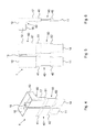
- the FIG. 1 shows an accumulator 2, in the housing 3, a mixing element 1 is arranged.
- a mixing element 1 is arranged in the housing 3 and a cell space 4 of the housing also electrode plates 5 are arranged, which are partially surrounded with separators, not shown.
- a housing rib 6 is located in the housing 3 or in the cell space 4.
- the mixing element 1 is fastened to the housing rib 6, for example clamped thereon.
- the mixing element 1 has a volume space 13 in the upper end region, which merges downwards into a thin flow channel 17, which has a comparatively substantially smaller cross-sectional area than the volume space 13.
- the flow channel 17 terminates in a lower region of the mixing element one or more openings 11.
- the volume space 13 is also open at the top, ie There is an opening 10. Because of the upper and lower openings 10, 11, a pressure equalization between the interior of the mixing element 1 and the surrounding space of the accumulator housing 3 is possible at any time. Therefore, in the mixing element 1, an electrolyte level 9, which corresponds to the electrolyte level 8 of the rechargeable battery 2 or of the respective cell space 4, is established.
- FIGS. 2 and 3 show the function of the mixing element 1 at a movement stress of the accumulator 2.
- the accumulator is tilted by a certain angle to the left. Due to this tilting, a level difference 12 initially results from the originally equal high levels 8, 9, since the electrolyte stored in the mixing element 1 can flow out only in a delayed manner through the thin flow channel 17.
- the outflow of the electrolyte into the cell space 4 of the accumulator is represented by the arrows. It is now assumed that the equalization process of the according to FIG. 2 is completed to the left tilted accumulator, so that the level 9 in the mixing element again corresponds to the level 8. Then suppose that the accumulator is now tilted, for example slightly to the right, as in FIG.
- the mixing element 1 is constructed so high with respect to the wall height of the volume space 13 that an over spilling of electrolytes with normal movement stress on the upper edge of the mixing element 1 is directly avoided in the volume space 13.
- Such spilling is ensured at specification according to the filling of the accumulator up to a tilt angle of 20 ° relative to the horizontal.
- the spillover of the electrolyte is ensured up to a tilt angle of 35 ° relative to the horizontal.
- the movement stress of the accumulator 2 is in everyday operation, i. when the accumulator 2 is installed in a vehicle, e.g. caused by the vehicle movements. Besides the vehicle movements caused by road bumps, longitudinal and lateral accelerations, e.g. when cornering, the described movement stress of the accumulator. 2
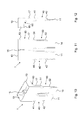
- FIGS. 4 to 6 show a first embodiment of the mixing element 1.
- the FIG. 4 shows an isometric view, the FIG. 5 a back view and the FIG. 6 a side view.
- the mixing element 1 on a recess 15, which divides the volume space 13 into two subspaces, but connected to each other with a relatively large cross-section are.
- the indentation 15 can serve for mounting the mixing element 1 on the housing rib 6, as in FIG FIG. 1 and FIG. 16 is recognizable.
- the mixing element can be easily attached to the housing rib and then clamped by means of the recess 15 thereon.
- the volume space 13 is bounded at the bottom by a bottom 16.
- the volume space 13 is formed open at the top through the opening 10.
- the volume space 13 passes below the bottom 16 in a transition region 60 in a thin flow channel 17, which extends down to an opening 11 down. Because of the division by the indentation 15, the thin flow channel 17 divides into two sub-channels 40, 50, the respective lower openings 11, 14 have.
- the openings 11, 14 may be formed as individual openings or as a combination of a plurality of openings.
- the mixing element can be straight in the region of the openings 11, 14 or, as can be seen in the figures, end with a chamfer.
- the thin flow channel 17 or the partial channels 40, 50 below the transition 60 has two linear discontinuities 41, 42, 51, 52.
- the circumference and thus also the internal cross-sectional area of the hollow body are reduced twice in the direction of the lower end region towards the opening 11, 14.
- FIGS. 7 to 9 show a second embodiment of the mixing element 1.
- the FIG. 7 shows an isometric view, the FIG. 8 a back view and the FIG. 9 a side view.
- the mixing element according to the FIGS. 4 to 6 has the mixing element 1 shown here in the lower regions of the flow channels 40, 50 each further divided sub-channels 43, 44, 53, 54, for example in the form of channels with a circular cross-section.
- Each of the sub-channels 43, 44, 53, 54 has its own circumference-reducing discontinuity 42, 52 and a lower opening 11, 14.
- FIGS. 10 to 12 show a third embodiment of the mixing element 1.
- the FIG. 10 shows an isometric view, the FIG. 11 a back view and the FIG. 12 a side view.
- the embodiment according to the FIGS. 10 to 12 corresponds to that of FIGS. 4 to 6 , with the difference that the back of the wall element 1, from which the indentation 15 emanates, is flat.
- the discontinuities 41, 42, 51, 52 are formed only laterally on the flow channels 40, 50 and on the front side, on which the volume space 13 protrudes.
- FIGS. 13 to 15 show a fourth embodiment of the mixing element.
- the FIG. 13 shows an isometric view, the FIG. 14 a back view and the FIG. 15 a side view.
- the flow channels 40, 50 are now also flat on the front side, ie the discontinuities 41, 42, 51, 52 are only provided laterally on the flow channels 40, 50.
- FIG. 16 shows a six-cell accumulator 2 in plan view, in turn, the lid of the accumulator is not yet placed.
- the six individual cell spaces 90, 91, 92, 93, 94, 95 and the electrode plates 5 arranged therein can therefore be seen.
- the electrode plates 5 extend in the same direction with respect to their largest dimension LE as the largest dimension LG of the housing 3 of the accumulator 2.
- the housing 3 has housing ribs 6.
- a mixing element 1 plugged onto a housing rib 6 is shown in each cell space 90, 91, 92, 93, 94, 95.
Landscapes
- Chemical & Material Sciences (AREA)
- Chemical Kinetics & Catalysis (AREA)
- Electrochemistry (AREA)
- General Chemical & Material Sciences (AREA)
- Engineering & Computer Science (AREA)
- Manufacturing & Machinery (AREA)
- Filling, Topping-Up Batteries (AREA)
- Secondary Cells (AREA)
Abstract
Description
- Die Erfindung betrifft ein Mischelement gemäß dem Oberbegriff des Anspruchs 1. Die Erfindung betrifft außerdem einen Akkumulator gemäß Anspruch 7.
- Allgemein betrifft die Erfindung das Gebiet von Akkumulatoren, die mit flüssigem Elektrolyten betrieben werden, d.h. wieder aufladbare elektrochemische Akkumulatoren z.B. in Form von Bleisäureakkumulatoren. Solche Akkumulatoren werden z.B. als Starterbatterien für Kraftfahrzeuge verwendet. Gattungsgemäße Mischelemente sind z.B. aus der
WO 2011/029035 A2 oder derDE 10 2010 048 428 A1 bekannt. - Der Erfindung liegt die Aufgabe zugrunde, ein hinsichtlich seiner Wirkungseffizienz weiter verbessertes Mischelement anzugeben. Ferner soll ein Akkumulator angegeben werden, bei dem der Effekt der Säureschichtung vermieden oder zumindest deutlich reduziert wird.
- Die Aufgabe wird gemäß Anspruch 1 gelöst durch ein Mischelement, das zum Einbau in ein Gehäuse eines mit flüssigem Elektrolyten betriebenen elektrochemischen Akkumulators eingerichtet ist, um den Elektrolyten in Folge von auf den Akkumulator im Betrieb ausgeübten Kräften und/oder Bewegungen zu durchmischen, wobei das Mischelement als an gegenüberliegenden Endbereichen mit jeweils wenigstens einer Öffnung versehener Hohlkörper ausgebildet ist, so dass in dem Hohlkörper ein Kanal gebildet ist, der in den gegenüberliegenden Endbereichen in die jeweilige wenigstens eine Öffnung mündet und dort umlaufend vom Material des Mischelements berandet ist, wobei das Mischelement im Bereich eines oberen Endbereichs, der dazu eingerichtet ist, beim Einbau in das Gehäuse oberhalb eines gegenüberliegenden unteren Endbereichs angeordnet zu sein, einen Volumenraum aufweist, dessen Umfang erheblich größer ist als der Umfang darunterliegender Abschnitte des Mischelements, so dass die darunterliegenden Abschnitte des Mischelements wenigstens einen im Vergleich zur Querschnittsfläche des Volumenkörpers dünnen Strömungskanal bilden, wobei sich der Umfang des Hohlkörpers im Bereich des dünnen Strömungskanals unterhalb eines Übergangs von dem Volumenraum in den dünnen Strömungskanal in Richtung zum unteren Endbereich hin verringert.
- Soweit von den Begriffen "oben" und "unten" Gebrauch gemacht wird, beziehen sich diese Angaben auf die spezifikationsgemäße Betriebslage des Akkumulators, d.h. eine im Wesentlichen horizontale Lage, bei der der AkkumulatorDeckel sowie dessen Einfüllöffnungen für den flüssigen Elektrolyten oben liegend sind. Bei einer üblichen, spezifikationsgemäßen Bewegungsbeanspruchung des Akkumulators ist eine gewisse Abweichung von der Horizontallage zulässig, wie es z.B. beim Betrieb eines Akkumulators in einem Kraftfahrzeug auftritt. Nicht spezifikationsgemäße Betriebslagen sind beispielsweise um 90° oder 180° gegenüber der Horizontallage gedrehte Lagen.
- Die Erfindung hat den Vorteil, dass mit dem erfindungsgemäßen Mischelement das gewünschte Durchmischen des Elektrolyten weiter verbessert wird. Hierdurch kann eine Säureschichtung in dem Akkumulator aufgehoben oder zumindest deutlich reduziert werden. Als Säureschichtung bezeichnet man unterschiedliche Säuredichten über die Höhe des Akkumulators. Das erfindungsgemäße Mischelement erlaubt ein Durchmischen des Elektrolyten mit höherer Wirkungseffizienz in Folge der Umfangsverringerung und der damit verbundenen Verringerung des Strömungsquerschnitts des Hohlkörpers im Bereich des dünnen Strömungskanals. Das erfindungsgemäße Mischelement erzeugt schon bei geringerer Bewegungsbeanspruchung des Akkumulators vergleichbare Durchmischeffekte wie Mischelemente aus dem Stand der Technik.
- Das Mischelement kann z.B. aus Polypropylen oder einem anderen geeigneten Material, das flexibel und säurebeständig ist, hergestellt sein.
- Das erfindungsgemäße Mischelement kann hinsichtlich seiner Höhe, d.h. seiner Längserstreckung in Vertikalrichtung in der vorgesehenen Einbaulage in den Akkumulator, so ausgebildet sein, dass sich ein zyklischer Umlauf des Elektrolyten bei Bewegungsbeanspruchung des Akkumulators derart ergibt, dass Elektrolyt über die Oberkante des Mischelements hinüberschwappt und über die untere Öffnung wieder abläuft, wie es z.B. in
US 5,096,787 beschrieben ist. In diesem Fall hat das Mischelement die Funktion einer hydrostatischen Pumpe. - Gemäß einer vorteilhaften Weiterbildung der Erfindung erstreckt sich das Mischelement mindestens soweit nach oben, dass bei spezifikationsgemäßer Bewegungsbeanspruchung des Akkumulators, wie sie z.B. bei einem fahrenden Fahrzeug auftritt, ein Überfließen von flüssigem Elektrolyten über den oberen Randbereich des Mischelements verhindert ist. Hierdurch kann vorteilhaft das Prinzip von kommunizierenden Röhren realisiert werden. Es wird eine Hin- und Herbewegung des Elektrolyten über eine kommunizierende Verbindung im unteren Bereich des Mischelements, d.h. durch die untere Öffnung, zwischen dem Volumenraum des Mischelements und dem umgebenden Zellraum des Akkumulators erzwungen und nicht, wie beim Prinzip der hydrostatischen Pumpe, ein Umwälzen des Elektrolyten. Dies hat den Vorteil, dass am Boden des Akkumulators angesammelter Schlamm dort verbleibt, da keine Umwälzung des Elektrolyten erfolgt. Die hierdurch erzwungene Elektrolytbewegung ist ausreichend, um den Elektrolyten soweit durchzumischen, dass eine Säureschichtung aufgehoben oder zumindest deutlich reduziert wird.
- Die kommunizierende Verbindung im unteren Bereich des Mischelements, d.h. die untere Öffnung, durch den der flüssige Elektrolyt hindurchströmen kann, kann auf unterschiedliche Weise ausgestaltet sein, z.B. in Form eines Spalts oder in Form einer oder mehrerer Öffnungen im unteren Bereich des Mischelements. Die zuvor erwähnten Öffnungen können an verschiedenen Stellen des Mischelements angeordnet sein, vorzugsweise natürlich im unteren Bereich des Strömungskanals.
- Gemäß einer vorteilhaften Weiterbildung der Erfindung ist das Mischelement als separates Bauteil hergestellt, das erst bei der Montage des Akkumulators in dessen Gehäuse eingesetzt wird. Das Mischelement kann z.B. als in einen Zellraum des Akkumulators einsteckbares Bauteil ausgebildet sein. Dies hat den Vorteil, dass das Mischelement separat hergestellt werden kann und bei Bedarf in den Zellraum eines Akkumulators eingesteckt werden kann. Auf diese Weise können auf kostengünstige Weise sowohl Akkumulatoren mit dem Mischelement als auch ohne das Mischelement hergestellt werden, ohne dass unterschiedliche Spritzgussformen für die Herstellung der Gehäuseteile der zwei Varianten des Akkumulators erforderlich wären, wie dies bei einem fest angeformten Wandelements erforderlich wäre. Zudem können auch Akkumulatoren aus bisheriger Serienfertigung in einfacher Weise, d.h. ohne große Aufwendungen bezüglich der Herstellungseinrichtungen, umgestellt werden auf Akkumulatoren mit integrierter Durchmischung in Form eines Mischelements.
- Das Mischelement kann insbesondere als ringförmiger Hohlkörper ausgebildet sein, wobei als Ringform in diesem Fall nicht ausschließlich eine Kreisringform verstanden wird, sondern auch jegliche anders geformte Ringformen. Das Mischelement kann z.B. als mit Ausnahme der in den gegenüberliegenden Endbereichen vorgesehenen Öffnungen im Wesentlichen geschlossener Hohlkörper ausgebildet sein. Dies erlaubt eine einfache Herstellung des Mischelements, z.B. aus einem Kunststoffmaterial.
- Vorteilhaft kann das Mischelement z.B. im Spritzgussverfahren mit einem Innendorn und einer Außenform hergestellt werden. Das Mischelement kann auch im Blasverfahren oder im Tiefziehverfahren als Hohlkörper hergestellt werden. Der sich hinsichtlich des Umfangs in Richtung zum unteren Endbereich hin verjüngende dünne Strömungskanal hat in diesem Zusammenhang den weiteren Vorteil, dass die Entformbarkeit des Mischelements beim Herstellprozess verbessert wird.
- Gemäß einer vorteilhaften Weiterbildung der Erfindung verläuft die Umfangsverringerung im Bereich des dünnen Strömungskanals über die Längserstreckung des Mischelements diskontinuierlich mit einer oder mehreren Diskontinuitäten. Hieraus resultiert eine Art stufenartige Verringerung des Umfangs des Hohlkörpers. Hierdurch kann die Wirkungseffizienz des Mischelements hinsichtlich des durch Durchmischungseffekts des flüssigen Elektrolyten weiter verbessert werden. Durch das Vorsehen von einer oder mehreren Diskontinuitäten im Verlauf des Strömungskanals ergeben sich abgestuft ein oder mehrere Übergänge des Strömungswiderstands und damit der Verlangsamung oder Beschleunigung des Austauschs des Elektrolyten zwischen dem Volumenraum des Mischelements und dem Innenraum des Akkumulators. Vorteilhaft können im Bereich des dünnen Strömungskanals z.B. zwei oder drei solche Diskontinuitäten vorgesehen werden. Auch die Entformbarkeit des Mischelements beim Herstellprozess wird durch die Diskontinuitäten weiter verbessert.
- Gemäß einer vorteilhaften Weiterbildung der Erfindung verlaufen eine oder mehrere Diskontinuitäten über die Längserstreckung des Mischelements linear, d.h. je nach Ausführungsform verläuft in diesen Bereichen die Umfangsverringerung oder die Querschnittsverringerung linear. Dies erlaubt eine einfache und kostengünstige Herstellung des Mischelements. Außerdem wird die mechanische Stabilität des dünnen Strömungskanals verbessert.
- Gemäß einer vorteilhaften Weiterbildung der Erfindung weist das Mischelement wenigstens zwei voneinander getrennte dünne Strömungskanäle auf, die mit dem gemeinsamen Volumenraum verbunden sind. Es können einer, mehrere oder alle der voneinander getrennten dünnen Strömungskanäle gemäß den zuvor erwähnten Merkmalen des dünnen Strömungskanals ausgebildet sein, insbesondere mit einer oder mehreren Diskontinuitäten.
- Gemäß einer vorteilhaften Weiterbildung der Erfindung weist das Mischelement zumindest an einer Seite des Hohlkörpers eine Einbuchtung auf, die in Längsrichtung des Mischelements verläuft und zur Aufnahme einer Gehäuserippe des Akkumulators eingerichtet ist. Dies erlaubt eine einfache und sichere mechanische Befestigung des Mischelements in dem Akkumulatorgehäuse, sofern dieses mit inneren Gehäuserippen ausgebildet ist. In diesem Fall sind keine zusätzlichen mechanischen Fixierungsmittel erforderlich. Die Einbuchtung kann insbesondere im Bereich des Volumenraums vorgesehen sein bzw. sich bis in diesen Raum erstrecken, so dass der Volumenraum geteilt ist.
- Gemäß einer vorteilhaften Weiterbildung der Erfindung ist die Tiefe der Einbuchtung wenigstens so groß wie die Erstreckung des dünnen Strömungskanals in derselben Richtung, d.h. in Ersteckungsrichtung der Einbuchtung. Dies erlaubt eine besonders robuste mechanische Fixierung des Mischelements an der Gehäuserippe des Gehäuses des Akkumulators. Außerdem werden hierdurch wenigstens zwei getrennte dünne Strömungskanäle geschaffen.
- Die Eingangs genannte Aufgabe wird gemäß Anspruch 7 gelöst durch einen Akkumulator mit einem Gehäuse, in dem wenigstens eine Akkumulatorzelle gebildet ist, wobei die Akkumulatorzelle eine Vielzahl von plattenförmigen Elektroden, die nebeneinander in der Akkumulatorzelle angeordnet sind, sowie flüssigen Elektrolyten aufweist, wobei in der Akkumulatorzelle zusätzlich in einem Freiraum wenigstens ein Mischelement der zuvor beschriebenen Art angeordnet ist. Bei dem erfindungsgemäßen Akkumulator wird bereits bei vergleichsweise geringer Bewegungsbeanspruchung ein hoher Durchmischungseffekt erzeugt und damit die Säureschichtung vermieden oder zumindest wesentlich reduziert.
- Gemäß einer vorteilhaften Weiterbildung der Erfindung ist das Mischelement seitlich von einer flachen Seite einer plattenförmigen Elektrode in der Akkumulatorzelle angeordnet. Das Mischelement wird hierdurch nicht von den hervorstehenden, zusammengeschweißten Enden der Separatortaschen kraftbeaufschlagt bzw. gehalten, wie in
DE 10 2010 048 428 A1 beschrieben, da es an der flachen Seite der plattenförmigen Elektrode angeordnet ist. Gemäß einer vorteilhaften Weiterbildung der Erfindung kann als Haltemittel zur mechanischen Fixierung des Mischelements in der Akkumulatorzelle ein in das Gehäuse des Akkumulators integriertes Bauteil vorgesehen sein. Insbesondere kann eine innere Gehäuserippe des Gehäuses des Akkumulators als Haltemittel genutzt werden. - Das Mischelement kann auch mit einem bekannten Fügeverfahren, z.B. Kunststoff-Schweißen, mit dem Gehäuse des Akkumulators bzw. der inneren Gehäuserippe verbunden sein und hierdurch lagefixiert sein.
- Gemäß einer vorteilhaften Weitebildung der Erfindung ist das Mischelement zwischen einer plattenförmigen Elektrode und der Gehäusewand oder einer an der Gehäusewand gebildeten inneren Gehäuserippe angeordnet.
- Gemäß einer vorteilhaften Weitebildung der Erfindung weist das Gehäuse eine Längserstreckung auf, die die größte Abmessung der Maße Höhe, Breite und Länge des Gehäuses ist, und die Elektrodenplatten weisen eine Längserstreckung auf, die die größte Abmessung der Maße Höhe, Breite und Länge der einzelnen Elektrodenplatte ist, und die Elektrodenplatten in einer Akkumulatorzelle sind derart ausgerichtet, dass die Längserstreckung der Elektrodenplatten im Wesentlichen in Richtung der Längserstreckung des Gehäuses verläuft. Dies erlaubt eine günstige, den vorhandenen Bauraum gut ausnutzende Unterbringung einer hohen Zahl von Elektrodenplatten in dem Gehäuse bei gleichzeitiger günstiger Unterbringung von einem oder mehreren Mischelementen in dem Gehäuse.
- Die Erfindung wird nachfolgend anhand von Ausführungsbeispielen unter Verwendung von Zeichnungen näher erläutert.
- Es zeigen
- Figur 1
- einen Akkumulator mit einem Mischelement in Querschnittsansicht und
- Figuren 2 und 3
- den Akkumulator gemäß
Figur 1 bei Bewegungsbeanspruchung und - Figuren 4 bis 6
- eine erste Ausführungsform eines Mischelements und
- Figuren 7 bis 9
- eine zweite Ausführungsform eines Mischelements und
- Figuren 10 bis 12
- eine dritte Ausführungsform eines Mischelements und
- Figuren 13 bis 15
- eine vierte Ausführungsform eines Mischelements und
- Figur 16
- einen Akkumulator in Draufsicht.
- In den Figuren werden gleiche Bezugszeichen für einander entsprechende Elemente verwendet. In sämtlichen Figuren wird der Akkumulator ohne Deckelteil dargestellt, d.h. in einem Zustand, in dem der Akkumulator an der Oberseite noch geöffnet ist. Zum Abschluss der Produktion erfolgt im Normalfall ein Verschließen des Akkumulatorgehäuses mit einem Deckelteil in der üblichen Weise.
- Die
Figur 1 zeigt einen Akkumulator 2, in dessen Gehäuse 3 ein Mischelement 1 angeordnet ist. In dem Gehäuse 3 bzw. einem Zellraum 4 des Gehäuses sind außerdem Elektrodenplatten 5 angeordnet, die zum Teil mit nicht dargestellten Separatoren umgeben sind. Außerdem befindet sich in dem Gehäuse 3 bzw. dem Zellraum 4 flüssiger Elektrolyt 7, wobei der Elektrolyt 7 bis zu einem Pegel 8 eingefüllt ist. Ferner befindet sich in dem Gehäuse 3 bzw. in dem Zellraum 4 eine Gehäuserippe 6. Das Mischelement 1 ist an der Gehäuserippe 6 befestigt, z.B. darauf aufgeklemmt. - Wie erkennbar ist, weist das Mischelement 1 im oberen Endbereich einen Volumenraum 13 auf, der nach unten hin in einen dünnen Strömungskanal 17 übergeht, der eine vergleichsweise wesentlich geringere Querschnittsfläche aufweist als der Volumenraum 13. Der Strömungskanal 17 endet in einem unteren Bereich des Mischelements in einer oder mehreren Öffnungen 11. Der Volumenraum 13 ist nach oben hin ebenfalls offen, d.h. dort befindet sich eine Öffnung 10. Wegen der oberen und der unteren Öffnungen 10, 11 ist jederzeit ein Druckausgleich zwischen dem Innenraum des Mischelements 1 und dem umgebenden Raum des Akkumulatorgehäuses 3 möglich. Es stellt sich in dem Mischelement 1 daher ein Elektrolytpegel 9 ein, der dem Elektrolytpegel 8 des Akkumulators 2 bzw. des jeweiligen Zellraums 4 entspricht.
- Die
Figuren 2 und 3 zeigen die Funktion des Mischelements 1 bei einer Bewegungsbeanspruchung des Akkumulators 2. GemäßFigur 2 wird der Akkumulator um einen bestimmten Winkel nach links gekippt. Aus den ursprünglich gleich hohen Pegeln 8, 9 ergibt sich aufgrund dieser Kippung zunächst eine Pegeldifferenz 12, da der im Mischelement 1 gespeicherte Elektrolyt durch den dünnen Strömungskanal 17 nur verzögert ausfließen kann. Das Ausfließen des Elektrolyten in den Zellraum 4 des Akkumulators wird durch die Pfeile dargestellt. Es sei nun angenommen, dass der Ausgleichsvorgang des gemäßFigur 2 nach links gekippten Akkumulators abgeschlossen ist, so dass der Pegel 9 im Mischelement wieder dem Pegel 8 entspricht. Sodann sei angenommen, dass der Akkumulator nun z.B. etwas nach rechts gekippt wird, wie inFigur 3 dargestellt ist. Es ergibt sich erneut eine Pegeldifferenz 12 zwischen den Pegeln 8, 9, diesmal jedoch in umgekehrter Richtung, d.h. gemäßFigur 3 ist der Pegel 9 niedriger als der Pegel 8. Dies führt dazu, dass durch die Öffnung 11 wieder Elektrolyt in das Mischelement 1 zurückströmt, wie durch die Pfeile dargestellt ist. Hierdurch wird ein Durchmischen des Elektrolyten erreicht und damit die Säureschichtung vermieden oder reduziert. Vorteilhaft ist das Mischelement 1 dabei hinsichtlich der Wandhöhe des Volumenraums 13 so hoch gebaut, dass ein Überschwappen von Elektrolyten bei normaler Bewegungsbeanspruchung über die Oberkante des Mischelements 1 direkt in den Volumenraum 13 vermieden wird. Ein solches Überschwappen wird bei spezifikationsgemäßer Befüllung des Akkumulators bis zu einem Kippwinkel von 20° gegenüber der Horizontalen gewährleistet. In einer weiteren Ausgestaltung wird das Überschwappen des Elektrolyten bis zu einem Kippwinkel von 35° gegenüber der Horizontalen gewährleistet. - Die Bewegungsbeanspruchung des Akkumulators 2 wird im Alltagsbetrieb, d.h. wenn der Akkumulator 2 in einem Fahrzeug eingebaut ist, z.B. durch die Fahrzeugbewegungen hervorgerufen. Außer den Fahrzeugbewegungen, die durch Fahrbahnunebenheiten hervorgerufen werden, führen auch Längs- und Querbeschleunigungen, z.B. bei Kurvenfahrt, zur beschriebenen Bewegungsbeanspruchung des Akkumulators 2.
- Die
Figuren 4 bis 6 zeigen eine erste Ausführungsform des Mischelements 1. DieFigur 4 zeigt dabei eine isometrische Ansicht, dieFigur 5 eine rückseitige Ansicht und dieFigur 6 eine Seitenansicht. Wie erkennbar ist, weist das Mischelement 1 eine Einbuchtung 15 auf, die den Volumenraum 13 in zwei Teilräume unterteilt, die jedoch mit relativ großem Querschnitt miteinander verbunden sind. Die Einbuchtung 15 kann zur Montage des Mischelements 1 auf der Gehäuserippe 6 dienen, wie inFigur 1 undFigur 16 erkennbar ist. Das Mischelement kann einfach auf die Gehäuserippe aufgesteckt werden und klemmt dann mittels der Einbuchtung 15 darauf fest. - Der Volumenraum 13 ist nach unten hin durch einen Boden 16 begrenzt. Der Volumenraum 13 ist nach oben hin durch die Öffnung 10 offen ausgebildet. Der Volumenraum 13 geht unterhalb des Bodens 16 in einem Übergangsbereich 60 über in einen dünnen Strömungskanal 17, der sich nach unten hin bis zu einer Öffnung 11 hin erstreckt. Wegen der Teilung durch die Einbuchtung 15 teilt sich der dünne Strömungskanal 17 in zwei Teilkanäle 40, 50 auf, die jeweilige untere Öffnungen 11, 14 aufweisen. Die Öffnungen 11, 14 können als einzelne Öffnungen oder als Kombination mehrerer Öffnungen ausgebildet sein. Das Mischelement kann im Bereich der Öffnungen 11, 14 gerade oder, wie in den Figuren erkennbar ist, mit einer Abschrägung enden.
- Wie ferner in den Zeichnungen erkennbar ist, weist der dünne Strömungskanal 17 bzw. die Teilkanäle 40, 50 unterhalb des Übergangs 60 zwei linear verlaufende Diskontinuitäten 41, 42, 51, 52 auf. Durch diese Diskontinuitäten verringert sich der Umfang und damit auch die innere Querschnittsfläche des Hohlkörpers zweifach in Richtung des unteren Endbereichs hin zu der Öffnung 11, 14.
- Die
Figuren 7 bis 9 zeigen eine zweite Ausführungsform des Mischelements 1. DieFigur 7 zeigt eine isometrische Ansicht, dieFigur 8 eine rückwärtige Ansicht und dieFigur 9 eine Seitenansicht. Im Unterschied zu dem Mischelement gemäß denFiguren 4 bis 6 weist das hier dargestellte Mischelement 1 in den unteren Bereichen der Strömungskanäle 40, 50 jeweils weiter aufgeteilte Teilkanäle 43, 44, 53, 54 auf, z.B. in Form von Kanälen mit kreisförmigem Querschnitt. Jeder der Teilkanäle 43, 44, 53, 54 weist eine eigene umfangsverringernde Diskontinuität 42, 52 sowie eine untere Öffnung 11, 14 auf. - Die
Figuren 10 bis 12 zeigen eine dritte Ausführungsform des Mischelements 1. DieFigur 10 zeigt eine isometrische Ansicht, dieFigur 11 eine rückwärtige Ansicht und dieFigur 12 eine Seitenansicht. Die Ausführungsform gemäß denFiguren 10 bis 12 entspricht derjenigen derFiguren 4 bis 6 , mit dem Unterschied, dass die Rückseite des Wandelements 1, von der aus die Einbuchtung 15 ausgeht, eben ausgebildet ist. Insbesondere die Diskontinuitäten 41, 42, 51, 52 sind nur seitlich an den Strömungskanälen 40, 50 und an der Vorderseite, an der der Volumenraum 13 vorsteht, ausgebildet. - Die
Figuren 13 bis 15 zeigen eine vierte Ausführungsform des Mischelements. DieFigur 13 zeigt eine isometrische Ansicht, dieFigur 14 eine rückwärtige Ansicht und dieFigur 15 eine Seitenansicht. Im Unterschied zur Ausführungsform derFiguren 10 bis 12 sind die Strömungskanäle 40, 50 nun auch an der Vorderseite eben ausgebildet, d.h. die Diskontinuitäten 41, 42, 51, 52 sind nur seitlich an den Strömungskanälen 40, 50 vorgesehen. - Die
Figur 16 zeigt einen sechszelligen Akkumulator 2 in Draufsicht, wobei wiederum der Deckel des Akkumulators noch nicht aufgesetzt ist. Erkennbar sind daher die sechs einzelnen Zellräume 90, 91, 92, 93, 94, 95 sowie die darin angeordneten Elektrodenplatten 5. Erkennbar ist, dass die Elektrodenplatten 5 sich hinsichtlich ihrer größten Abmessung LE in der gleichen Richtung erstrecken wie die größte Abmessung LG des Gehäuses 3 des Akkumulators 2. Erkennbar ist ferner, dass das Gehäuse 3 Gehäuserippen 6 aufweist. Beispielhaft ist ein auf eine Gehäuserippe 6 aufgestecktes Mischelement 1 in jedem Zellraum 90, 91, 92, 93, 94, 95 dargestellt.
Claims (11)
- Mischelement (1), das zum Einbau in ein Gehäuse (3) eines mit flüssigem Elektrolyten (7) betriebenen elektrochemischen Akkumulators (2) eingerichtet ist, um den Elektrolyten (7) in Folge von auf den Akkumulator (2) im Betrieb ausgeübten Kräften und/oder Bewegungen zu durchmischen, dadurch gekennzeichnet, dass das Mischelement (1) als an gegenüberliegenden Endbereichen mit jeweils wenigstens einer Öffnung (10, 11, 14) versehener Hohlkörper ausgebildet ist, so dass in dem Hohlkörper ein Kanal gebildet ist, der in den gegenüberliegenden Endbereichen in die jeweilige wenigstens eine Öffnung (10, 11, 14) mündet und dort umlaufend vom Material des Mischelements (1) berandet ist, wobei das Mischelement (1) im Bereich eines oberen Endbereichs, der dazu eingerichtet ist, beim Einbau in das Gehäuse (3) oberhalb eines gegenüberliegenden unteren Endbereichs angeordnet zu sein, einen Volumenraum (13) aufweist, dessen Umfang erheblich größer ist als der Umfang darunterliegender Abschnitte des Mischelements (1), so dass die darunterliegenden Abschnitte des Mischelements (1) wenigstens einen im Vergleich zur Querschnittsfläche des Volumenkörpers (13) dünnen Strömungskanal (17) bilden, wobei sich der Umfang des Hohlkörpers im Bereich des dünnen Strömungskanals unterhalb (17) eines Übergangs (60) von dem Volumenraum (13) in den dünnen Strömungskanal (17) in Richtung zum unteren Endbereich hin verringert.
- Mischelement nach Anspruch 1, dadurch gekennzeichnet, dass die Umfangsverringerung im Bereich des dünnen Strömungskanals (17) über die Längserstreckung des Mischelements (1) diskontinuierlich mit einer oder mehreren Diskontinuitäten (41, 42, 51, 52) verläuft.
- Mischelement nach Anspruch 2, dadurch gekennzeichnet, dass eine oder mehrere Diskontinuitäten (41, 42, 51, 52) über die Längserstreckung des Mischelements (1) linear verlaufen.
- Mischelement nach einem der vorhergehenden Ansprüche, dadurch gekennzeichnet, dass das Mischelement (1) wenigstens zwei voneinander getrennte dünne Strömungskanäle (40, 50, 43, 44, 53, 54) aufweist, die mit dem gemeinsamen Volumenraum (13) verbunden sind.
- Mischelement nach einem der vorhergehenden Ansprüche, dadurch gekennzeichnet, dass das Mischelement (1) als im Spritzgussverfahren mit einem Innendorn und einer Außenform, im Blasverfahren oder im Tiefziehverfahren hergestellter Hohlkörper ausgebildet ist.
- Mischelement nach einem der vorhergehenden Ansprüche, dadurch gekennzeichnet, dass das Mischelement (1) zumindest an einer Seite des Hohlkörpers eine Einbuchtung (15) aufweist, die in Längsrichtung des Mischelements (1) verläuft und zur Aufnahme einer Gehäuserippe (6) des Gehäuses (3) des Akkumulators (2) eingerichtet ist.
- Akkumulator (2) mit einem Gehäuse (3), in dem wenigstens eine Akkumulatorzelle (90, 91, 92, 93, 94, 95) gebildet ist, wobei die Akkumulatorzelle (90, 91, 92, 93, 94, 95) eine Vielzahl von plattenförmigen Elektroden (5), die nebeneinander in der Akkumulatorzelle angeordnet sind, sowie flüssigen Elektrolyten (7) aufweist, wobei in der Akkumulatorzelle (90, 91, 92, 93, 94, 95) zusätzlich in einem Freiraum wenigstens ein Mischelement (1) nach einem der vorhergehenden Ansprüche angeordnet ist.
- Akkumulator nach Anspruch 7, dadurch gekennzeichnet, dass das Mischelement (1) seitlich von einer flachen Seite einer plattenförmigen Elektrode (5) in der Akkumulatorzelle (90, 91, 92, 93, 94, 95) angeordnet ist.
- Akkumulator nach Anspruch 7 oder 8, dadurch gekennzeichnet, dass das Mischelement (1) zwischen einer plattenförmigen Elektrode (5) und der Gehäusewand oder einer an der Gehäusewand gebildeten inneren Gehäuserippe (6) angeordnet ist.
- Akkumulator nach einem der Ansprüche 7 bis 9, dadurch gekennzeichnet, dass das Gehäuse (3) eine Längserstreckung (LG) aufweist, die die größte Abmessung der Maße Höhe, Breite und Länge des Gehäuses (3) ist, die Elektrodenplatten (5) eine Längserstreckung (LE) aufweisen, die die größte Abmessung der Maße Höhe, Breite und Länge der einzelnen Elektrodenplatte (5) ist, und die Elektrodenplatten (5) in einer Akkumulatorzelle (90, 91, 92, 93, 94, 95) derart ausgerichtet sind, dass die Längserstreckung (LE) der Elektrodenplatten (5) im Wesentlichen in Richtung der Längserstreckung (LG) des Gehäuses (3) verläuft.
- Akkumulator nach einem der Ansprüche 7 bis 10, dadurch gekennzeichnet, dass sich das Mischelement (1) mindestens so weit nach oben erstreckt, dass bei spezifikationsgemäßer Bewegungsbeanspruchung des Akkumulators (2) ein Überfließen von flüssigem Elektrolyten (7) über den oberen Randbereich des Mischelements (1) verhindert ist.
Applications Claiming Priority (1)
| Application Number | Priority Date | Filing Date | Title |
|---|---|---|---|
| DE102012110897.8A DE102012110897A1 (de) | 2012-11-13 | 2012-11-13 | Mischelement sowie Akkumulator mit wenigstens einem Mischelement |
Publications (2)
| Publication Number | Publication Date |
|---|---|
| EP2731176A1 true EP2731176A1 (de) | 2014-05-14 |
| EP2731176B1 EP2731176B1 (de) | 2017-02-01 |
Family
ID=49578183
Family Applications (1)
| Application Number | Title | Priority Date | Filing Date |
|---|---|---|---|
| EP13192764.2A Active EP2731176B1 (de) | 2012-11-13 | 2013-11-13 | Mischelement sowie Akkumulator mit wenigstens einem Mischelement |
Country Status (3)
| Country | Link |
|---|---|
| EP (1) | EP2731176B1 (de) |
| BR (1) | BR102013029129B1 (de) |
| DE (1) | DE102012110897A1 (de) |
Cited By (1)
| Publication number | Priority date | Publication date | Assignee | Title |
|---|---|---|---|---|
| TWI632723B (zh) * | 2014-05-27 | 2018-08-11 | iQ力量授權公司 | 用於將液體電解質電池的電解質混勻的裝置及液體電解質電池 |
Families Citing this family (5)
| Publication number | Priority date | Publication date | Assignee | Title |
|---|---|---|---|---|
| EP2912709B1 (de) | 2012-11-28 | 2016-08-24 | IQ Power Licensing AG | Batterie mit elektrolytdurchmischungsvorrichtung |
| DE102014019930B4 (de) | 2014-01-24 | 2024-07-25 | Clarios Germany Gmbh & Co. Kgaa | Mischelement und Akkumulator |
| MA39508B1 (fr) * | 2014-05-27 | 2018-09-28 | Iq Power Licensing Ag | Dispositif de mélange de l'électrolyte d'une batterie à électrolyte liquide et batterie à électrolyte liquide |
| WO2019217759A1 (en) | 2018-05-09 | 2019-11-14 | Amtek Research International Llc | Acid stratification mitigation, electrolytes, devices, and methods related thereto |
| DE202019101339U1 (de) * | 2019-03-08 | 2020-06-09 | Hoppecke Batterien Gmbh & Co. Kg | Batteriegehäuse und Batterie |
Citations (5)
| Publication number | Priority date | Publication date | Assignee | Title |
|---|---|---|---|---|
| US5032476A (en) * | 1990-07-19 | 1991-07-16 | Globe-Union, Inc. | Internal hydrostatic pump for a mobile vehicle battery |
| US5096787A (en) | 1990-08-03 | 1992-03-17 | Globe-Union Inc. | Hydrostatic pump with static resistance for a mobile vehicle battery |
| WO2011029035A2 (en) | 2009-09-04 | 2011-03-10 | Johnson Controls Technology Company | Secondary battery with improved acid destratification |
| WO2012048885A1 (de) * | 2010-10-15 | 2012-04-19 | Vb Autobatterie Gmbh & Co. Kgaa | Akkumulator mit einem wandelement und wandelement dafür |
| DE102010048428A1 (de) | 2010-10-15 | 2012-04-19 | Vb Autobatterie Gmbh & Co. Kgaa | Akkumulator mit einem Wandelement und Wandelement dafür |
Family Cites Families (1)
| Publication number | Priority date | Publication date | Assignee | Title |
|---|---|---|---|---|
| AU2794089A (en) * | 1988-05-31 | 1990-01-05 | Globe-Union Inc. | Internal hydrostatic pump for a mobile vehicle battery |
-
2012
- 2012-11-13 DE DE102012110897.8A patent/DE102012110897A1/de not_active Withdrawn
-
2013
- 2013-11-12 BR BR102013029129-3A patent/BR102013029129B1/pt active IP Right Grant
- 2013-11-13 EP EP13192764.2A patent/EP2731176B1/de active Active
Patent Citations (5)
| Publication number | Priority date | Publication date | Assignee | Title |
|---|---|---|---|---|
| US5032476A (en) * | 1990-07-19 | 1991-07-16 | Globe-Union, Inc. | Internal hydrostatic pump for a mobile vehicle battery |
| US5096787A (en) | 1990-08-03 | 1992-03-17 | Globe-Union Inc. | Hydrostatic pump with static resistance for a mobile vehicle battery |
| WO2011029035A2 (en) | 2009-09-04 | 2011-03-10 | Johnson Controls Technology Company | Secondary battery with improved acid destratification |
| WO2012048885A1 (de) * | 2010-10-15 | 2012-04-19 | Vb Autobatterie Gmbh & Co. Kgaa | Akkumulator mit einem wandelement und wandelement dafür |
| DE102010048428A1 (de) | 2010-10-15 | 2012-04-19 | Vb Autobatterie Gmbh & Co. Kgaa | Akkumulator mit einem Wandelement und Wandelement dafür |
Cited By (1)
| Publication number | Priority date | Publication date | Assignee | Title |
|---|---|---|---|---|
| TWI632723B (zh) * | 2014-05-27 | 2018-08-11 | iQ力量授權公司 | 用於將液體電解質電池的電解質混勻的裝置及液體電解質電池 |
Also Published As
| Publication number | Publication date |
|---|---|
| DE102012110897A1 (de) | 2014-05-15 |
| BR102013029129B1 (pt) | 2021-03-09 |
| BR102013029129A2 (pt) | 2014-10-21 |
| EP2731176B1 (de) | 2017-02-01 |
Similar Documents
| Publication | Publication Date | Title |
|---|---|---|
| EP3097597B1 (de) | Mischelement, sortiment von mischelementen und akkumulator | |
| EP2731176B1 (de) | Mischelement sowie Akkumulator mit wenigstens einem Mischelement | |
| EP3467898B1 (de) | Akkumulator mit einem wandelement und wandelement dafür | |
| DE102013003247A1 (de) | Kraftstoffbehälter | |
| EP2220706B1 (de) | Akkumulator | |
| DE102010048428A1 (de) | Akkumulator mit einem Wandelement und Wandelement dafür | |
| EP4284670B1 (de) | Flüssigkeitstank für ein flüssigkeitssystem eines fahrzeugs, flüssigkeitssystem und fahrzeug | |
| EP2617086B1 (de) | Batterie, batteriekasten und verfahren zur herstellung einer batterie | |
| DE2752850A1 (de) | Verbesserungen an elektrischen batterien und verfahren zur herstellung einer elektrischen verbindung zwischen den zellen einer batterie | |
| WO2009050286A1 (de) | Separator für gelelektrolytakkumulatoren | |
| DE102017223124A1 (de) | Mehrteiliger spritzgegossener Mehrkammer-Kunststofftank mit schrägliegender Fügefläche | |
| DE102014019930B4 (de) | Mischelement und Akkumulator | |
| DE102010033645A1 (de) | Deckelteil für einen Akkumulator und Akkumulator mit einem solchen Deckelteil | |
| WO2020229276A1 (de) | Batteriegehäuse und batterie mit einem solchen | |
| DE102023108732A1 (de) | Zwischenzellkühlelement, Batterieanordnung, Kraftfahrzeug und Verfahren zum Herstellen eines Zwischenzellkühlelements | |
| DE102023128242A1 (de) | Stapelbares batteriemodul und batteriesystem für ein batteriebetriebenes fahrzeug | |
| EP2956975B1 (de) | Fixierungselement und akkumulator | |
| EP3935692B1 (de) | Versetzte polbuchsen und energiespeichersystem mit den gleichen | |
| WO2018127410A1 (de) | Stopfen zum verschliessen und abdichten einer öffnung in einem gehäuse eines energiespeichersystems und energiespeichersystem | |
| DE10254950B4 (de) | Akkumulator, insbesondere Bleiakkumulator | |
| EP1335443B1 (de) | Schwingungsfester Akkumulator und Verfahren zu dessen Herstellung | |
| DE102018123687B4 (de) | Batteriekasten einer Blockbatterie | |
| WO2018029050A1 (de) | Verbindungselement für einen batteriekasten sowie batteriebaukasten und verfahren zu seiner herstellung | |
| DE102023005185A1 (de) | Kompaktes Modul für einen Temperiermittelkreislauf | |
| DE202023002970U1 (de) | Kompaktes Modul für einen Temperiermittelkreislauf |
Legal Events
| Date | Code | Title | Description |
|---|---|---|---|
| PUAI | Public reference made under article 153(3) epc to a published international application that has entered the european phase |
Free format text: ORIGINAL CODE: 0009012 |
|
| 17P | Request for examination filed |
Effective date: 20131113 |
|
| AK | Designated contracting states |
Kind code of ref document: A1 Designated state(s): AL AT BE BG CH CY CZ DE DK EE ES FI FR GB GR HR HU IE IS IT LI LT LU LV MC MK MT NL NO PL PT RO RS SE SI SK SM TR |
|
| AX | Request for extension of the european patent |
Extension state: BA ME |
|
| R17P | Request for examination filed (corrected) |
Effective date: 20141112 |
|
| RBV | Designated contracting states (corrected) |
Designated state(s): AL AT BE BG CH CY CZ DE DK EE ES FI FR GB GR HR HU IE IS IT LI LT LU LV MC MK MT NL NO PL PT RO RS SE SI SK SM TR |
|
| 17Q | First examination report despatched |
Effective date: 20150304 |
|
| GRAP | Despatch of communication of intention to grant a patent |
Free format text: ORIGINAL CODE: EPIDOSNIGR1 |
|
| RIC1 | Information provided on ipc code assigned before grant |
Ipc: H01M 10/06 20060101ALN20160728BHEP Ipc: H01M 10/42 20060101ALI20160728BHEP Ipc: H01M 2/02 20060101ALI20160728BHEP Ipc: H01M 2/38 20060101AFI20160728BHEP |
|
| INTG | Intention to grant announced |
Effective date: 20160810 |
|
| STAA | Information on the status of an ep patent application or granted ep patent |
Free format text: STATUS: GRANT OF PATENT IS INTENDED |
|
| GRAS | Grant fee paid |
Free format text: ORIGINAL CODE: EPIDOSNIGR3 |
|
| GRAA | (expected) grant |
Free format text: ORIGINAL CODE: 0009210 |
|
| STAA | Information on the status of an ep patent application or granted ep patent |
Free format text: STATUS: THE PATENT HAS BEEN GRANTED |
|
| AK | Designated contracting states |
Kind code of ref document: B1 Designated state(s): AL AT BE BG CH CY CZ DE DK EE ES FI FR GB GR HR HU IE IS IT LI LT LU LV MC MK MT NL NO PL PT RO RS SE SI SK SM TR |
|
| REG | Reference to a national code |
Ref country code: GB Ref legal event code: FG4D Free format text: NOT ENGLISH |
|
| REG | Reference to a national code |
Ref country code: CH Ref legal event code: EP Ref country code: AT Ref legal event code: REF Ref document number: 866240 Country of ref document: AT Kind code of ref document: T Effective date: 20170215 |
|
| REG | Reference to a national code |
Ref country code: IE Ref legal event code: FG4D Free format text: LANGUAGE OF EP DOCUMENT: GERMAN |
|
| REG | Reference to a national code |
Ref country code: DE Ref legal event code: R096 Ref document number: 502013006226 Country of ref document: DE |
|
| REG | Reference to a national code |
Ref country code: NL Ref legal event code: MP Effective date: 20170201 |
|
| REG | Reference to a national code |
Ref country code: LT Ref legal event code: MG4D |
|
| PG25 | Lapsed in a contracting state [announced via postgrant information from national office to epo] |
Ref country code: HR Free format text: LAPSE BECAUSE OF FAILURE TO SUBMIT A TRANSLATION OF THE DESCRIPTION OR TO PAY THE FEE WITHIN THE PRESCRIBED TIME-LIMIT Effective date: 20170201 Ref country code: LT Free format text: LAPSE BECAUSE OF FAILURE TO SUBMIT A TRANSLATION OF THE DESCRIPTION OR TO PAY THE FEE WITHIN THE PRESCRIBED TIME-LIMIT Effective date: 20170201 Ref country code: GR Free format text: LAPSE BECAUSE OF FAILURE TO SUBMIT A TRANSLATION OF THE DESCRIPTION OR TO PAY THE FEE WITHIN THE PRESCRIBED TIME-LIMIT Effective date: 20170502 Ref country code: IS Free format text: LAPSE BECAUSE OF FAILURE TO SUBMIT A TRANSLATION OF THE DESCRIPTION OR TO PAY THE FEE WITHIN THE PRESCRIBED TIME-LIMIT Effective date: 20170601 Ref country code: FI Free format text: LAPSE BECAUSE OF FAILURE TO SUBMIT A TRANSLATION OF THE DESCRIPTION OR TO PAY THE FEE WITHIN THE PRESCRIBED TIME-LIMIT Effective date: 20170201 Ref country code: NO Free format text: LAPSE BECAUSE OF FAILURE TO SUBMIT A TRANSLATION OF THE DESCRIPTION OR TO PAY THE FEE WITHIN THE PRESCRIBED TIME-LIMIT Effective date: 20170501 |
|
| PG25 | Lapsed in a contracting state [announced via postgrant information from national office to epo] |
Ref country code: PL Free format text: LAPSE BECAUSE OF FAILURE TO SUBMIT A TRANSLATION OF THE DESCRIPTION OR TO PAY THE FEE WITHIN THE PRESCRIBED TIME-LIMIT Effective date: 20170201 Ref country code: NL Free format text: LAPSE BECAUSE OF FAILURE TO SUBMIT A TRANSLATION OF THE DESCRIPTION OR TO PAY THE FEE WITHIN THE PRESCRIBED TIME-LIMIT Effective date: 20170201 Ref country code: RS Free format text: LAPSE BECAUSE OF FAILURE TO SUBMIT A TRANSLATION OF THE DESCRIPTION OR TO PAY THE FEE WITHIN THE PRESCRIBED TIME-LIMIT Effective date: 20170201 Ref country code: LV Free format text: LAPSE BECAUSE OF FAILURE TO SUBMIT A TRANSLATION OF THE DESCRIPTION OR TO PAY THE FEE WITHIN THE PRESCRIBED TIME-LIMIT Effective date: 20170201 Ref country code: BG Free format text: LAPSE BECAUSE OF FAILURE TO SUBMIT A TRANSLATION OF THE DESCRIPTION OR TO PAY THE FEE WITHIN THE PRESCRIBED TIME-LIMIT Effective date: 20170501 Ref country code: SE Free format text: LAPSE BECAUSE OF FAILURE TO SUBMIT A TRANSLATION OF THE DESCRIPTION OR TO PAY THE FEE WITHIN THE PRESCRIBED TIME-LIMIT Effective date: 20170201 Ref country code: ES Free format text: LAPSE BECAUSE OF FAILURE TO SUBMIT A TRANSLATION OF THE DESCRIPTION OR TO PAY THE FEE WITHIN THE PRESCRIBED TIME-LIMIT Effective date: 20170201 Ref country code: PT Free format text: LAPSE BECAUSE OF FAILURE TO SUBMIT A TRANSLATION OF THE DESCRIPTION OR TO PAY THE FEE WITHIN THE PRESCRIBED TIME-LIMIT Effective date: 20170601 |
|
| PG25 | Lapsed in a contracting state [announced via postgrant information from national office to epo] |
Ref country code: RO Free format text: LAPSE BECAUSE OF FAILURE TO SUBMIT A TRANSLATION OF THE DESCRIPTION OR TO PAY THE FEE WITHIN THE PRESCRIBED TIME-LIMIT Effective date: 20170201 Ref country code: EE Free format text: LAPSE BECAUSE OF FAILURE TO SUBMIT A TRANSLATION OF THE DESCRIPTION OR TO PAY THE FEE WITHIN THE PRESCRIBED TIME-LIMIT Effective date: 20170201 Ref country code: CZ Free format text: LAPSE BECAUSE OF FAILURE TO SUBMIT A TRANSLATION OF THE DESCRIPTION OR TO PAY THE FEE WITHIN THE PRESCRIBED TIME-LIMIT Effective date: 20170201 Ref country code: SK Free format text: LAPSE BECAUSE OF FAILURE TO SUBMIT A TRANSLATION OF THE DESCRIPTION OR TO PAY THE FEE WITHIN THE PRESCRIBED TIME-LIMIT Effective date: 20170201 |
|
| REG | Reference to a national code |
Ref country code: DE Ref legal event code: R097 Ref document number: 502013006226 Country of ref document: DE |
|
| REG | Reference to a national code |
Ref country code: FR Ref legal event code: PLFP Year of fee payment: 5 |
|
| PG25 | Lapsed in a contracting state [announced via postgrant information from national office to epo] |
Ref country code: DK Free format text: LAPSE BECAUSE OF FAILURE TO SUBMIT A TRANSLATION OF THE DESCRIPTION OR TO PAY THE FEE WITHIN THE PRESCRIBED TIME-LIMIT Effective date: 20170201 Ref country code: SM Free format text: LAPSE BECAUSE OF FAILURE TO SUBMIT A TRANSLATION OF THE DESCRIPTION OR TO PAY THE FEE WITHIN THE PRESCRIBED TIME-LIMIT Effective date: 20170201 |
|
| PLBE | No opposition filed within time limit |
Free format text: ORIGINAL CODE: 0009261 |
|
| STAA | Information on the status of an ep patent application or granted ep patent |
Free format text: STATUS: NO OPPOSITION FILED WITHIN TIME LIMIT |
|
| 26N | No opposition filed |
Effective date: 20171103 |
|
| PG25 | Lapsed in a contracting state [announced via postgrant information from national office to epo] |
Ref country code: SI Free format text: LAPSE BECAUSE OF FAILURE TO SUBMIT A TRANSLATION OF THE DESCRIPTION OR TO PAY THE FEE WITHIN THE PRESCRIBED TIME-LIMIT Effective date: 20170201 |
|
| PG25 | Lapsed in a contracting state [announced via postgrant information from national office to epo] |
Ref country code: MC Free format text: LAPSE BECAUSE OF FAILURE TO SUBMIT A TRANSLATION OF THE DESCRIPTION OR TO PAY THE FEE WITHIN THE PRESCRIBED TIME-LIMIT Effective date: 20170201 |
|
| PG25 | Lapsed in a contracting state [announced via postgrant information from national office to epo] |
Ref country code: CH Free format text: LAPSE BECAUSE OF NON-PAYMENT OF DUE FEES Effective date: 20171130 Ref country code: LI Free format text: LAPSE BECAUSE OF NON-PAYMENT OF DUE FEES Effective date: 20171130 |
|
| PG25 | Lapsed in a contracting state [announced via postgrant information from national office to epo] |
Ref country code: LU Free format text: LAPSE BECAUSE OF NON-PAYMENT OF DUE FEES Effective date: 20171113 |
|
| REG | Reference to a national code |
Ref country code: BE Ref legal event code: MM Effective date: 20171130 |
|
| REG | Reference to a national code |
Ref country code: IE Ref legal event code: MM4A |
|
| PG25 | Lapsed in a contracting state [announced via postgrant information from national office to epo] |
Ref country code: MT Free format text: LAPSE BECAUSE OF FAILURE TO SUBMIT A TRANSLATION OF THE DESCRIPTION OR TO PAY THE FEE WITHIN THE PRESCRIBED TIME-LIMIT Effective date: 20170201 |
|
| PG25 | Lapsed in a contracting state [announced via postgrant information from national office to epo] |
Ref country code: IE Free format text: LAPSE BECAUSE OF NON-PAYMENT OF DUE FEES Effective date: 20171113 |
|
| PG25 | Lapsed in a contracting state [announced via postgrant information from national office to epo] |
Ref country code: BE Free format text: LAPSE BECAUSE OF NON-PAYMENT OF DUE FEES Effective date: 20171130 |
|
| PG25 | Lapsed in a contracting state [announced via postgrant information from national office to epo] |
Ref country code: HU Free format text: LAPSE BECAUSE OF FAILURE TO SUBMIT A TRANSLATION OF THE DESCRIPTION OR TO PAY THE FEE WITHIN THE PRESCRIBED TIME-LIMIT; INVALID AB INITIO Effective date: 20131113 |
|
| REG | Reference to a national code |
Ref country code: DE Ref legal event code: R082 Ref document number: 502013006226 Country of ref document: DE Representative=s name: MEISSNER BOLTE PATENTANWAELTE RECHTSANWAELTE P, DE |
|
| PG25 | Lapsed in a contracting state [announced via postgrant information from national office to epo] |
Ref country code: CY Free format text: LAPSE BECAUSE OF NON-PAYMENT OF DUE FEES Effective date: 20170201 |
|
| PG25 | Lapsed in a contracting state [announced via postgrant information from national office to epo] |
Ref country code: MK Free format text: LAPSE BECAUSE OF FAILURE TO SUBMIT A TRANSLATION OF THE DESCRIPTION OR TO PAY THE FEE WITHIN THE PRESCRIBED TIME-LIMIT Effective date: 20170201 |
|
| REG | Reference to a national code |
Ref country code: AT Ref legal event code: MM01 Ref document number: 866240 Country of ref document: AT Kind code of ref document: T Effective date: 20181113 |
|
| PG25 | Lapsed in a contracting state [announced via postgrant information from national office to epo] |
Ref country code: AT Free format text: LAPSE BECAUSE OF NON-PAYMENT OF DUE FEES Effective date: 20181113 |
|
| PG25 | Lapsed in a contracting state [announced via postgrant information from national office to epo] |
Ref country code: TR Free format text: LAPSE BECAUSE OF FAILURE TO SUBMIT A TRANSLATION OF THE DESCRIPTION OR TO PAY THE FEE WITHIN THE PRESCRIBED TIME-LIMIT Effective date: 20170201 |
|
| PG25 | Lapsed in a contracting state [announced via postgrant information from national office to epo] |
Ref country code: AL Free format text: LAPSE BECAUSE OF FAILURE TO SUBMIT A TRANSLATION OF THE DESCRIPTION OR TO PAY THE FEE WITHIN THE PRESCRIBED TIME-LIMIT Effective date: 20170201 |
|
| REG | Reference to a national code |
Ref country code: DE Ref legal event code: R079 Ref document number: 502013006226 Country of ref document: DE Free format text: PREVIOUS MAIN CLASS: H01M0002380000 Ipc: H01M0050700000 |
|
| REG | Reference to a national code |
Ref country code: DE Ref legal event code: R082 Ref document number: 502013006226 Country of ref document: DE Representative=s name: MEISSNER BOLTE PATENTANWAELTE RECHTSANWAELTE P, DE Ref country code: DE Ref legal event code: R081 Ref document number: 502013006226 Country of ref document: DE Owner name: CLARIOS GERMANY GMBH & CO. KGAA, DE Free format text: FORMER OWNER: JOHNSON CONTROLS AUTOBATTERIE GMBH & CO. KGAA, 30419 HANNOVER, DE |
|
| P01 | Opt-out of the competence of the unified patent court (upc) registered |
Free format text: CASE NUMBER: APP_1525/2025 Effective date: 20250109 |
|
| PGFP | Annual fee paid to national office [announced via postgrant information from national office to epo] |
Ref country code: DE Payment date: 20251128 Year of fee payment: 13 |
|
| PGFP | Annual fee paid to national office [announced via postgrant information from national office to epo] |
Ref country code: GB Payment date: 20251127 Year of fee payment: 13 |
|
| PGFP | Annual fee paid to national office [announced via postgrant information from national office to epo] |
Ref country code: IT Payment date: 20251119 Year of fee payment: 13 |
|
| PGFP | Annual fee paid to national office [announced via postgrant information from national office to epo] |
Ref country code: FR Payment date: 20251125 Year of fee payment: 13 |