EP2730366B1 - Rack, in particular for a slidable gate, and process for the obtainment thereof - Google Patents
Rack, in particular for a slidable gate, and process for the obtainment thereof Download PDFInfo
- Publication number
- EP2730366B1 EP2730366B1 EP13192025.8A EP13192025A EP2730366B1 EP 2730366 B1 EP2730366 B1 EP 2730366B1 EP 13192025 A EP13192025 A EP 13192025A EP 2730366 B1 EP2730366 B1 EP 2730366B1
- Authority
- EP
- European Patent Office
- Prior art keywords
- rack
- longitudinal
- bending
- gates
- connector portion
- Prior art date
- Legal status (The legal status is an assumption and is not a legal conclusion. Google has not performed a legal analysis and makes no representation as to the accuracy of the status listed.)
- Active
Links
Images


Classifications
-
- B—PERFORMING OPERATIONS; TRANSPORTING
- B21—MECHANICAL METAL-WORKING WITHOUT ESSENTIALLY REMOVING MATERIAL; PUNCHING METAL
- B21D—WORKING OR PROCESSING OF SHEET METAL OR METAL TUBES, RODS OR PROFILES WITHOUT ESSENTIALLY REMOVING MATERIAL; PUNCHING METAL
- B21D53/00—Making other particular articles
- B21D53/26—Making other particular articles wheels or the like
- B21D53/28—Making other particular articles wheels or the like gear wheels
-
- B—PERFORMING OPERATIONS; TRANSPORTING
- B23—MACHINE TOOLS; METAL-WORKING NOT OTHERWISE PROVIDED FOR
- B23P—METAL-WORKING NOT OTHERWISE PROVIDED FOR; COMBINED OPERATIONS; UNIVERSAL MACHINE TOOLS
- B23P15/00—Making specific metal objects by operations not covered by a single other subclass or a group in this subclass
- B23P15/14—Making specific metal objects by operations not covered by a single other subclass or a group in this subclass gear parts, e.g. gear wheels
-
- E—FIXED CONSTRUCTIONS
- E05—LOCKS; KEYS; WINDOW OR DOOR FITTINGS; SAFES
- E05F—DEVICES FOR MOVING WINGS INTO OPEN OR CLOSED POSITION; CHECKS FOR WINGS; WING FITTINGS NOT OTHERWISE PROVIDED FOR, CONCERNED WITH THE FUNCTIONING OF THE WING
- E05F15/00—Power-operated mechanisms for wings
- E05F15/60—Power-operated mechanisms for wings using electrical actuators
- E05F15/603—Power-operated mechanisms for wings using electrical actuators using rotary electromotors
- E05F15/632—Power-operated mechanisms for wings using electrical actuators using rotary electromotors for horizontally-sliding wings
- E05F15/635—Power-operated mechanisms for wings using electrical actuators using rotary electromotors for horizontally-sliding wings operated by push-pull mechanisms, e.g. flexible or rigid rack-and-pinion arrangements
-
- F—MECHANICAL ENGINEERING; LIGHTING; HEATING; WEAPONS; BLASTING
- F16—ENGINEERING ELEMENTS AND UNITS; GENERAL MEASURES FOR PRODUCING AND MAINTAINING EFFECTIVE FUNCTIONING OF MACHINES OR INSTALLATIONS; THERMAL INSULATION IN GENERAL
- F16H—GEARING
- F16H55/00—Elements with teeth or friction surfaces for conveying motion; Worms, pulleys or sheaves for gearing mechanisms
- F16H55/02—Toothed members; Worms
- F16H55/26—Racks
-
- E—FIXED CONSTRUCTIONS
- E05—LOCKS; KEYS; WINDOW OR DOOR FITTINGS; SAFES
- E05Y—INDEXING SCHEME ASSOCIATED WITH SUBCLASSES E05D AND E05F, RELATING TO CONSTRUCTION ELEMENTS, ELECTRIC CONTROL, POWER SUPPLY, POWER SIGNAL OR TRANSMISSION, USER INTERFACES, MOUNTING OR COUPLING, DETAILS, ACCESSORIES, AUXILIARY OPERATIONS NOT OTHERWISE PROVIDED FOR, APPLICATION THEREOF
- E05Y2201/00—Constructional elements; Accessories therefor
- E05Y2201/60—Suspension or transmission members; Accessories therefor
- E05Y2201/622—Suspension or transmission members elements
- E05Y2201/71—Toothed gearing
- E05Y2201/722—Racks
-
- E—FIXED CONSTRUCTIONS
- E05—LOCKS; KEYS; WINDOW OR DOOR FITTINGS; SAFES
- E05Y—INDEXING SCHEME ASSOCIATED WITH SUBCLASSES E05D AND E05F, RELATING TO CONSTRUCTION ELEMENTS, ELECTRIC CONTROL, POWER SUPPLY, POWER SIGNAL OR TRANSMISSION, USER INTERFACES, MOUNTING OR COUPLING, DETAILS, ACCESSORIES, AUXILIARY OPERATIONS NOT OTHERWISE PROVIDED FOR, APPLICATION THEREOF
- E05Y2600/00—Mounting or coupling arrangements for elements provided for in this subclass
- E05Y2600/40—Mounting location; Visibility of the elements
- E05Y2600/46—Mounting location; Visibility of the elements in or on the wing
-
- E—FIXED CONSTRUCTIONS
- E05—LOCKS; KEYS; WINDOW OR DOOR FITTINGS; SAFES
- E05Y—INDEXING SCHEME ASSOCIATED WITH SUBCLASSES E05D AND E05F, RELATING TO CONSTRUCTION ELEMENTS, ELECTRIC CONTROL, POWER SUPPLY, POWER SIGNAL OR TRANSMISSION, USER INTERFACES, MOUNTING OR COUPLING, DETAILS, ACCESSORIES, AUXILIARY OPERATIONS NOT OTHERWISE PROVIDED FOR, APPLICATION THEREOF
- E05Y2900/00—Application of doors, windows, wings or fittings thereof
- E05Y2900/40—Application of doors, windows, wings or fittings thereof for gates
Definitions
- the present invention regards a rack, in particular for a slidable gate, and a process for the obtainment thereof, according to the preamble of the respective independent claims.
- the present rack is advantageously inserted in the field of production of gate accessories, employable for delimiting an entrance passage, for vehicles or pedestrians, for the access to a property, structure, company, building or garden.
- the rack is for example intended to be fixed at the lower edge of the gate and to be engaged with the pinion of a motor, usually fixed to the ground next to the gate itself.
- the rack, object of the present invention can of course also be applied in other positions of the gate (e.g. at an upper bar) or more generally it can be employed in other mechanical applications in order to transmit the motion of the pinion of a motor to a movable element.
- the slidable gates with mechanized movement conventionally comprise a support framework, below which the rack is fixed along the extension of the gate.
- the aforesaid movement is obtained by means of a motor housed in a box placed alongside the gate; from such motor, a pinion projects that comes to be engaged in the rack fixed to the gate, at one side thereof, i.e. laterally on the monorail.
- the pinion can have preferably horizontal axis, and consequently the rack will have the teeth directed outwardly from one side of the gate.
- slidable carriages in order to allow the movement between the closed and open positions, two or more idle wheels are mounted in line below the frame; such wheels slide in a guided manner on a track embedded in the concrete.
- at least two carriages are provided, spaced from each other and aligned in the advancing direction of the gate.
- Each carriage is rigidly constrained to the ground by means of a structure equipped with foundations, and it is provided with a plurality of idle wheels inserted inside a monorail fixed to the lower crosspiece of the gate in order to guide the latter during its opening and closing movement.
- gates In order to conceal the rack, gates have more recently arrived on the market that have a metal support profile fixed laterally to the gate, with a rack associated that is directed towards the ground and engaged by a motorized pinion susceptible of rotating around a horizontal axis.
- the racks for gates currently known and present on the market are obtained in a single body made of metal, usually steel, and have thickness greater than 8 mm, and usually 8 or 12 mm, even though for some large-gate applications thicknesses of over 30 mm are provided.
- the production process for the racks conventionally provides for the creation of metal bars obtained through hot rolling with the desired thickness and height.
- teeth are created by means of removal of material, e.g. with slotting operations (processing with a tool with alternating rectilinear vertical motion) or with milling operations (cutting processing with a tool adapted to erode the material, obtaining the form of the teeth).
- a further drawback of the production processes currently known for obtaining racks lies in the need to subject the wire rods, obtained in the desired thickness by means of hot rolling processes, to additional surface operations by means of washing and pickling operations for the removal of calamine and subsequent galvanizing operations, which negatively affect the overall cost of the finished product.
- Document US 3,711,915 discloses a rack consisting of two flat plates, linearly elongated in a predominant longitudinal extension, bearing toothings, each formed by a sequence of parallel teeth.
- the two plates are realized by a cutting torch and are secured together in side-by-side relationship so that the teeth of the toothing of a plate are arranged aligned with the teeth of the toothing of the other plate.
- This rack is very expansive to be produced.
- Document NL 1004700 discloses a mechanical body consisting of two flat portions joined together by a transversal portion; the two flat portions are facing and substantially parallel to each other, and have first longitudinal connection ends joined together by said transversal portion, and second longitudinal ends bearing toothings, each formed by a sequence of parallel teeth; the two flat portions with the two toothings form two corresponding racks suitable to be independently engaged by a separate gear wheel.
- the two racks are separated by a guide for a wheel. Also this well known rack is very expansive to be produced.
- the problem underlying the present invention is therefore that of eliminating the drawbacks of the art known up to now, by providing a process for obtaining a rack, which is particularly inexpensive and at the same time quick to achieve.
- a further object of the present finding is to provide a process for obtaining a rack that is operatively simple to obtain and which employs machines that are not particularly costly and commonly used in the processing of metal sheets, and in particular in the processing of metal sheet strips with low thickness.
- a further object of the present finding is to provide a rack, in particular for gates, which is structurally simple, inexpensive to achieve and entirely reliable in operation.
- a further object of the present finding is to provide a rack, in particular for gates, which is simple to install on the structure of the gate.
- a further object of the present finding is to provide a rack, in particular for gates, which is mechanically resistant to all possible stresses transmitted thereto by the pinion of the gate movement motor.
- a further object of the present finding is to provide a rack, in particular for gates, which does not negatively affect the aesthetics of the gate, allowing an architectural design entirely free of mechanical requirements.
- reference number 1 indicates an embodiment of a rack, object of the present invention, intended to be advantageously mounted on a slidable gate.
- the rack can be employed for moving any one other slidable body, different from the gate, and it can be obtained in the desired length.
- the gate 2 is extended with its load-bearing structure 2' mainly along an advancement direction X with respect to which it can be normally moved between an open position and a closed position.
- the gate 2 is supported by means of wheels 21 on a track 22 fixed to the ground, or, in accordance with the embodiment illustrated in figure 1 , it is supported and guided by carriages fixed to the ground (not illustrated) and being engaged with the rollers in a rail integral with the gate 2.
- Movement means are provided for moving the gate 2 along its advancement direction, which comprise the rack 1 integral with the gate 2 and a motor 6 fixed integral with the ground, placed on one side of the gate 2 and provided with a pinion 8 mechanically engaged with the rack 1.
- the rack 1 is obtained with a body made of metal material, in particular steel adapted to endure in an open environment, or for such purpose subjected to surface protection treatments, linearly elongated in a predominant longitudinal extension direction indicated with Y in the figures.
- the rack 1 can be advantageously obtained by fixing multiple sections aligned with each other, e.g. of 1 meter length. Such fixing can occur for example by means of welding, or with slots obtained together with the toothing.
- the rack 1 is fixed to a lower crosspiece of the support structure 2' of the gate 2 with the toothing directed downward in order to be engaged with the pinion 8 of the motor 6 having horizontal rotation axis.
- the rack can also be fixed with the teeth directed horizontally in order to be engaged on a pinion with vertical axis.
- the rack will have mechanical strength susceptible of resisting the stresses transmitted by the movement of the gate.
- the aforesaid elongated body is provided with two flat portions 10 arranged facing, substantially parallel to each other.
- Each flat portion 10 has a first connection end 11 with longitudinal extension that is joined to the first connection end 11 of the other flat portion with a connector portion 12, which has 180-degree shape with at least one bend and is adapted to connect the two flat portions 10 without interruption.
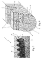
- the rack 1 preferably has a U-shaped cross section obtained with a single bend obtained at the longitudinal median line of the elongated body made of metal material and with the two arms formed by the flat portions 10 approached or pressed on each other.
- the rack 1 can otherwise have the connector portion 12 with 180-degree shape by means of two bends, each 90 degrees (or otherwise by means of multiple bends whose overall angle is 180 degrees) obtained via cold deformation of a steel strip or sheet.
- the second longitudinal ends 13 of the elongated body each bear a toothing 14 formed by a sequence of parallel teeth 15.
- Each sequence of teeth is then extended along the aforesaid longitudinal extension direction Y with the teeth 15 of the toothing 14 of a flat portion 10 transversely arranged aligned with the teeth 15 of the toothing 14 of the other flat portion 10 in order to allow the pinion 8 to simultaneously engage both toothings 14.
- the curved connector portion 12 with 180 degree bend has, in at least one intermediate section 16 thereof, a low thickness. Such thinning allows, as specified hereinbelow, preventing elastic returns of the two flat portions aimed to open them and at the same time allows minimizing the use of steel, representing a reduction of material.
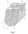
- the connector portion 12 of the elongated body curved with 180 degree bend, has at the bottom of the bend an enlargement or slot 160 aimed to slightly separate the two arms.
- Such slot is substantially closed at the top by the two approached flat portions.
- Such enlargement allows directing the same arms against each other towards the second longitudinal ends 13 of the elongated body, so that the toothings 14 of the two flat portions 10 are arranged side-by-side and leaned against each other.
- the connector portion 12 also performs the function of closing, from the top, the slit possibly present between the two flat portions 10, in the position at which the rack 1 is usually intended to be mounted on the frame of the gate, i.e. with the teeth 15 directed downward as represented in the enclosed figure 1 .
- the connector portion 12 prevents the water from penetrating inside the slit, thus preventing the onset of corrosion phenomena or the opening of the same slit.
- the two flat portions 10 will be arranged facing and parallel but not leaned against each other, with multiple bends that while defining the curved connector portion 12 with 180 degree bend maintain the flat portions 10 thereof spaced.
- the overall transverse thickness D of the rack 1, for discharging the mechanical stresses will in any case be substantially determined by the sum of the thicknesses d of its two flat portions 10 and will therefore have the value set by the requirements of the specific application.
- the main thicknesses of the racks 1 are 8 or 12 mm with thicknesses of the flat portions thus respectively 4 and 6 mm.
- the thicknesses of the flat portions can consequently be smaller or lower.
- the thickness of the flat portions will be comprised between 2 mm and 6 mm.
- such thicknesses allow applying the racks in the field of the gates, by engaging the teeth with pinions of gate movement motors without risking that the aforesaid flat portions are deformed, i.e. without requiring guide means for preventing their deformation.
- Also forming an object of the present invention is a process for obtaining a rack, in particular for gates, advantageously but not exclusively obtained according to the characteristics of the above-described rack; for the sake of description simplicity, the same reference numbers will be maintained hereinbelow.
- a step is provided for arranging an elongated strip 100 made of metal material, in particular steel, obtained in the desired thickness advantageously through a step of cold rolling.
- the strip 100 indeed has a thickness d preferably compatible with the normal cold rolling processes, having a final thickness less than 8 mm and in particular less than 6 mm.
- the elongated strip 100 is provided with a predominant longitudinal extension direction, indicated with Y in the enclosed figures, and is laterally delimited on the sides by two parallel longitudinal edges 101.
- each sequence of teeth 15 is extended along the aforesaid longitudinal extension direction Y.
- Such step of bending by means of one or more bends is aimed to arrange, facing and parallel to each other, two flat portions 10 of the elongated strip 100 placed at the sides of the median line M, creating a connector portion 12 curved 180° at the latter.
- the two flat portions 10 first have longitudinal connection ends 11 joined together due to the curved connector portion 12 with 180 degree bend at the line of bending and second longitudinal ends 13 bearing the aforesaid toothings 14.
- the bending step is obtained with a single bend carried out with respect to the median longitudinal line M, by deforming the connector portion 12 in the form of U curved 180°.
- the connector portion 12 has 180-degree shape by means of said bending step, with two or more bends carried out along two or more corresponding longitudinal lines parallel to the extension of the elongated strip 100.
- the bending step is in any case achieved by means of cold deformation of the strip.
- the arrangement of the teeth 15 of the two toothings is obtained during the shearing step with the teeth transversely aligned on the two portions 10, in a manner such that after the bending step the same teeth 15 of the toothing 14 of each flat portion 10 are maintained aligned with the teeth of the toothing of the other flat portion 10.
- object of the present invention in the case of a single bend, in order to facilitate the bending of the elongated strip 100 and oppose the elastic opening return of the flat portions 10 after the bending step, a step of thinning the elongated strip 100 at the median longitudinal line M is provided for, carried out after the shearing step and before the bending step.
- Such thinning step is advantageously obtained without removal of material by simple deformation through compression, in particular with roller aimed at transversely enlarging the elongated strip 100 by compressing it at the median longitudinal line M.
- the bending step initially provides for bending the flat portions 10, orienting them with tilt towards each other and then closing the bend created in the connector portion 12 in order to force the approaching of the two flat portions 10 against each other.
- Such process can lead to having a greater distance of the arms of the U-shaped section at the bottom of the bend with respect to the second longitudinal ends 13 with the associated toothings 14.
- Such displacement at the bend is indicated with 160 in figure 5 .
- the step of shearing the elongated strip 100 at its parallel longitudinal edges 101 for the formation of two toothings 14, each composed of a sequence of parallel teeth 15 that are transversely aligned with those of the other toothing 14 is preferably obtained by means of a metal sheet shearing press well-known to the man skilled in the art.
- Such machine is particularly suitable for shearing sheet metal such as steel for not particularly high thicknesses, preferably 4 or 6 mm and in any case less than 8 mm.
- the bending step is obtained preferably by acting via a forming machine on the elongated strip 100 whose parallel longitudinal edges 101 are already cut.
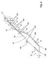
- the forming machine is provided with a plurality of pairs of rollers 102, which sequentially deform the elongated strip 100, bringing it from a flattened conformation to a bent conformation with one or more longitudinal bends adapted to shape the connector portion 12 substantially 180 degrees.
- a single bend can be provided for, along a median longitudinal line adapted to confer a substantially U-shaped form to the connector portion 12, or two 90-degree bends can be provided for (i.e. multiple bends whose overall angular sum is equal to 180 degrees) adapted to confer an overall U-shaped 180-degree form to the connector portion 12 with the two parallel and facing flat portions 10 joined by an orthogonal flat intermediate portion that acts as a spacer between the two flat portions 10.
- the thinning step mentioned above can advantageously be obtained by means of a compression roller (not illustrated) mounted on the same forming machine in central position with respect to the width of the elongated strip 100.
- the elongated strip 100 In the case of use of a forming machine, the elongated strip 100 must have a continuous extension, or it will have length such to be driven by the rollers of the forming machine (e.g. being unwound by a coil). At the same time, the same elongated strip 100 will be cut before entering the forming machine by means of the press, still in the form of continuous strip.
- the cut and folded strip assumes the shape of a continuous rack and is separated into sections with predefined length that are fixed in a row on the frame of the gate 2, advantageously via welding or via fixing, by means of spacers and screws, at a base crosspiece thereof (or also at the rail in the gates of cantilever type) in order to obtain the rack of the desired length, generally equal to that of the gate.
- shearing step sections of elongated strip are first cut (shearing step) at the longitudinal edges 101 in a first shearing station (or of a first series of stations) and then bent 180 degrees with one or more bends (bending step) at longitudinal lines parallel to the extension of the strip (i.e. in the case of a single bend at the median line M of the strip) in subsequent bending stations.
- a single median bend there can for example be two bending stations in succession, of which the first is adapted to form the elongated strip 100 with the two flat portions 10 bent 90 degrees and the second, after the movement of the section bend in a suitable position, is adapted to close the two flat portions 10 against each other in order to form the 180 degree bend.
Landscapes
- Engineering & Computer Science (AREA)
- Mechanical Engineering (AREA)
- General Engineering & Computer Science (AREA)
- Transmission Devices (AREA)
Applications Claiming Priority (1)
| Application Number | Priority Date | Filing Date | Title |
|---|---|---|---|
| IT000331A ITPD20120331A1 (it) | 2012-11-07 | 2012-11-07 | Cremagliera in particolare per cancello scorrevole e procedimento per la sua realizzazione |
Publications (2)
| Publication Number | Publication Date |
|---|---|
| EP2730366A1 EP2730366A1 (en) | 2014-05-14 |
| EP2730366B1 true EP2730366B1 (en) | 2016-08-31 |
Family
ID=47428868
Family Applications (1)
| Application Number | Title | Priority Date | Filing Date |
|---|---|---|---|
| EP13192025.8A Active EP2730366B1 (en) | 2012-11-07 | 2013-11-07 | Rack, in particular for a slidable gate, and process for the obtainment thereof |
Country Status (3)
| Country | Link |
|---|---|
| EP (1) | EP2730366B1 (pl) |
| IT (1) | ITPD20120331A1 (pl) |
| PL (1) | PL2730366T3 (pl) |
Families Citing this family (1)
| Publication number | Priority date | Publication date | Assignee | Title |
|---|---|---|---|---|
| ITUB20154713A1 (it) * | 2015-10-22 | 2017-04-22 | Comunello Flii Spa | Cremagliera per cancello scorrevole e procedimento per la sua realizzazione |
Family Cites Families (5)
| Publication number | Priority date | Publication date | Assignee | Title |
|---|---|---|---|---|
| US1670476A (en) * | 1926-03-23 | 1928-05-22 | Dura Co | Method of forming racks for use in window regulators |
| US3711915A (en) * | 1971-08-05 | 1973-01-23 | W Wright | Method of making toothed racks |
| NL1004700C1 (nl) * | 1996-08-22 | 1998-02-26 | Ven Beheer B V Van De | Overbrenging. |
| JP2002263761A (ja) * | 2001-03-09 | 2002-09-17 | Koyo Seiko Co Ltd | 中空ラック軸およびその製造方法 |
| GB0816861D0 (en) * | 2008-09-15 | 2008-10-22 | Minivator Ltd | Rack and method of forming the same |
-
2012
- 2012-11-07 IT IT000331A patent/ITPD20120331A1/it unknown
-
2013
- 2013-11-07 EP EP13192025.8A patent/EP2730366B1/en active Active
- 2013-11-07 PL PL13192025T patent/PL2730366T3/pl unknown
Also Published As
| Publication number | Publication date |
|---|---|
| EP2730366A1 (en) | 2014-05-14 |
| PL2730366T3 (pl) | 2017-02-28 |
| ITPD20120331A1 (it) | 2014-05-08 |
Similar Documents
| Publication | Publication Date | Title |
|---|---|---|
| DE102007059439B3 (de) | Vorrichtung und Verfahren zum Kaltwalzprofilieren von Profilen mit veränderlicher Höhe | |
| CN100421832C (zh) | 成形型材的方法 | |
| WO2014008137A1 (en) | Solar panel rack | |
| CA2744552A1 (en) | Curved building panel, building structure, panel curving system and methods for making curved building panels | |
| EP3150295B1 (en) | Machine and method for the semi-continuous cold-bending of sections with low ductility | |
| EP2730366B1 (en) | Rack, in particular for a slidable gate, and process for the obtainment thereof | |
| WO2015058256A1 (en) | Panel assembly | |
| CN212762136U (zh) | 冷弯成型机 | |
| DE4031388C2 (de) | Seitensektionaltor oder Rundlauftor, Deckensektionaltor | |
| RU2701305C1 (ru) | Способ изготовления элемента осадительного электрода электрофильтра | |
| CN209736441U (zh) | 一种板材切断折边机构 | |
| US20120131974A1 (en) | Arching metallic profiles in continous in-line process | |
| EP3088091B1 (en) | Roll-forming method | |
| EP3653831A1 (en) | Slidable gate | |
| WO2008022436A1 (en) | A roll-forming machine for forming smooth curves in profiled panel sections and method of forming curved panels | |
| EP4579055A1 (en) | Plant for making roller shutter sheets | |
| US12060750B2 (en) | Process for manufacturing an interlocking molding with sightline elimination flange for toilet and other partitions | |
| JP3771698B2 (ja) | デッキプレートの製造装置 | |
| CN116372020B (zh) | 一种门窗边框型材冷弯成型系统及工艺 | |
| CN212944723U (zh) | 一种热镀锌带钢矫直装置 | |
| CN221590138U (zh) | 一种屋顶型板及成型设备 | |
| EP3126072B1 (de) | Dressurvorrichtung | |
| CN104400548B (zh) | 一种单组铰链型垂向导轨防护罩 | |
| ITPD20140039U1 (it) | Carrello per cancello scorrevole a sbalzo | |
| EP2444583B1 (de) | Torsäule für ein Rolltor |
Legal Events
| Date | Code | Title | Description |
|---|---|---|---|
| PUAI | Public reference made under article 153(3) epc to a published international application that has entered the european phase |
Free format text: ORIGINAL CODE: 0009012 |
|
| 17P | Request for examination filed |
Effective date: 20131107 |
|
| AK | Designated contracting states |
Kind code of ref document: A1 Designated state(s): AL AT BE BG CH CY CZ DE DK EE ES FI FR GB GR HR HU IE IS IT LI LT LU LV MC MK MT NL NO PL PT RO RS SE SI SK SM TR |
|
| AX | Request for extension of the european patent |
Extension state: BA ME |
|
| R17P | Request for examination filed (corrected) |
Effective date: 20141111 |
|
| RBV | Designated contracting states (corrected) |
Designated state(s): AL AT BE BG CH CY CZ DE DK EE ES FI FR GB GR HR HU IE IS IT LI LT LU LV MC MK MT NL NO PL PT RO RS SE SI SK SM TR |
|
| 17Q | First examination report despatched |
Effective date: 20150506 |
|
| GRAP | Despatch of communication of intention to grant a patent |
Free format text: ORIGINAL CODE: EPIDOSNIGR1 |
|
| RIC1 | Information provided on ipc code assigned before grant |
Ipc: B21D 53/28 20060101ALI20160218BHEP Ipc: E05F 15/635 20150101ALI20160218BHEP Ipc: B23P 15/14 20060101AFI20160218BHEP Ipc: F16H 55/26 20060101ALI20160218BHEP |
|
| INTG | Intention to grant announced |
Effective date: 20160316 |
|
| RAP1 | Party data changed (applicant data changed or rights of an application transferred) |
Owner name: FRATELLI COMUNELLO S.P.A. |
|
| GRAS | Grant fee paid |
Free format text: ORIGINAL CODE: EPIDOSNIGR3 |
|
| GRAA | (expected) grant |
Free format text: ORIGINAL CODE: 0009210 |
|
| AK | Designated contracting states |
Kind code of ref document: B1 Designated state(s): AL AT BE BG CH CY CZ DE DK EE ES FI FR GB GR HR HU IE IS IT LI LT LU LV MC MK MT NL NO PL PT RO RS SE SI SK SM TR |
|
| REG | Reference to a national code |
Ref country code: CH Ref legal event code: EP Ref country code: GB Ref legal event code: FG4D |
|
| REG | Reference to a national code |
Ref country code: IE Ref legal event code: FG4D |
|
| REG | Reference to a national code |
Ref country code: DE Ref legal event code: R096 Ref document number: 602013010860 Country of ref document: DE |
|
| REG | Reference to a national code |
Ref country code: AT Ref legal event code: REF Ref document number: 824572 Country of ref document: AT Kind code of ref document: T Effective date: 20161015 |
|
| REG | Reference to a national code |
Ref country code: FR Ref legal event code: PLFP Year of fee payment: 4 |
|
| REG | Reference to a national code |
Ref country code: LT Ref legal event code: MG4D |
|
| REG | Reference to a national code |
Ref country code: NL Ref legal event code: MP Effective date: 20160831 |
|
| REG | Reference to a national code |
Ref country code: AT Ref legal event code: MK05 Ref document number: 824572 Country of ref document: AT Kind code of ref document: T Effective date: 20160831 |
|
| PG25 | Lapsed in a contracting state [announced via postgrant information from national office to epo] |
Ref country code: RS Free format text: LAPSE BECAUSE OF FAILURE TO SUBMIT A TRANSLATION OF THE DESCRIPTION OR TO PAY THE FEE WITHIN THE PRESCRIBED TIME-LIMIT Effective date: 20160831 Ref country code: HR Free format text: LAPSE BECAUSE OF FAILURE TO SUBMIT A TRANSLATION OF THE DESCRIPTION OR TO PAY THE FEE WITHIN THE PRESCRIBED TIME-LIMIT Effective date: 20160831 Ref country code: NO Free format text: LAPSE BECAUSE OF FAILURE TO SUBMIT A TRANSLATION OF THE DESCRIPTION OR TO PAY THE FEE WITHIN THE PRESCRIBED TIME-LIMIT Effective date: 20161130 Ref country code: FI Free format text: LAPSE BECAUSE OF FAILURE TO SUBMIT A TRANSLATION OF THE DESCRIPTION OR TO PAY THE FEE WITHIN THE PRESCRIBED TIME-LIMIT Effective date: 20160831 Ref country code: LT Free format text: LAPSE BECAUSE OF FAILURE TO SUBMIT A TRANSLATION OF THE DESCRIPTION OR TO PAY THE FEE WITHIN THE PRESCRIBED TIME-LIMIT Effective date: 20160831 |
|
| PG25 | Lapsed in a contracting state [announced via postgrant information from national office to epo] |
Ref country code: GR Free format text: LAPSE BECAUSE OF FAILURE TO SUBMIT A TRANSLATION OF THE DESCRIPTION OR TO PAY THE FEE WITHIN THE PRESCRIBED TIME-LIMIT Effective date: 20161201 Ref country code: ES Free format text: LAPSE BECAUSE OF FAILURE TO SUBMIT A TRANSLATION OF THE DESCRIPTION OR TO PAY THE FEE WITHIN THE PRESCRIBED TIME-LIMIT Effective date: 20160831 Ref country code: NL Free format text: LAPSE BECAUSE OF FAILURE TO SUBMIT A TRANSLATION OF THE DESCRIPTION OR TO PAY THE FEE WITHIN THE PRESCRIBED TIME-LIMIT Effective date: 20160831 Ref country code: SE Free format text: LAPSE BECAUSE OF FAILURE TO SUBMIT A TRANSLATION OF THE DESCRIPTION OR TO PAY THE FEE WITHIN THE PRESCRIBED TIME-LIMIT Effective date: 20160831 Ref country code: AT Free format text: LAPSE BECAUSE OF FAILURE TO SUBMIT A TRANSLATION OF THE DESCRIPTION OR TO PAY THE FEE WITHIN THE PRESCRIBED TIME-LIMIT Effective date: 20160831 Ref country code: BE Free format text: LAPSE BECAUSE OF NON-PAYMENT OF DUE FEES Effective date: 20161130 Ref country code: LV Free format text: LAPSE BECAUSE OF FAILURE TO SUBMIT A TRANSLATION OF THE DESCRIPTION OR TO PAY THE FEE WITHIN THE PRESCRIBED TIME-LIMIT Effective date: 20160831 |
|
| REG | Reference to a national code |
Ref country code: SK Ref legal event code: T3 Ref document number: E 22625 Country of ref document: SK |
|
| PG25 | Lapsed in a contracting state [announced via postgrant information from national office to epo] |
Ref country code: EE Free format text: LAPSE BECAUSE OF FAILURE TO SUBMIT A TRANSLATION OF THE DESCRIPTION OR TO PAY THE FEE WITHIN THE PRESCRIBED TIME-LIMIT Effective date: 20160831 Ref country code: RO Free format text: LAPSE BECAUSE OF FAILURE TO SUBMIT A TRANSLATION OF THE DESCRIPTION OR TO PAY THE FEE WITHIN THE PRESCRIBED TIME-LIMIT Effective date: 20160831 |
|
| PG25 | Lapsed in a contracting state [announced via postgrant information from national office to epo] |
Ref country code: BE Free format text: LAPSE BECAUSE OF FAILURE TO SUBMIT A TRANSLATION OF THE DESCRIPTION OR TO PAY THE FEE WITHIN THE PRESCRIBED TIME-LIMIT Effective date: 20160831 Ref country code: SM Free format text: LAPSE BECAUSE OF FAILURE TO SUBMIT A TRANSLATION OF THE DESCRIPTION OR TO PAY THE FEE WITHIN THE PRESCRIBED TIME-LIMIT Effective date: 20160831 Ref country code: PT Free format text: LAPSE BECAUSE OF FAILURE TO SUBMIT A TRANSLATION OF THE DESCRIPTION OR TO PAY THE FEE WITHIN THE PRESCRIBED TIME-LIMIT Effective date: 20170102 Ref country code: DK Free format text: LAPSE BECAUSE OF FAILURE TO SUBMIT A TRANSLATION OF THE DESCRIPTION OR TO PAY THE FEE WITHIN THE PRESCRIBED TIME-LIMIT Effective date: 20160831 Ref country code: BG Free format text: LAPSE BECAUSE OF FAILURE TO SUBMIT A TRANSLATION OF THE DESCRIPTION OR TO PAY THE FEE WITHIN THE PRESCRIBED TIME-LIMIT Effective date: 20161130 |
|
| REG | Reference to a national code |
Ref country code: DE Ref legal event code: R097 Ref document number: 602013010860 Country of ref document: DE |
|
| REG | Reference to a national code |
Ref country code: CH Ref legal event code: PL |
|
| PLBE | No opposition filed within time limit |
Free format text: ORIGINAL CODE: 0009261 |
|
| STAA | Information on the status of an ep patent application or granted ep patent |
Free format text: STATUS: NO OPPOSITION FILED WITHIN TIME LIMIT |
|
| PG25 | Lapsed in a contracting state [announced via postgrant information from national office to epo] |
Ref country code: LI Free format text: LAPSE BECAUSE OF NON-PAYMENT OF DUE FEES Effective date: 20161130 Ref country code: CH Free format text: LAPSE BECAUSE OF NON-PAYMENT OF DUE FEES Effective date: 20161130 |
|
| 26N | No opposition filed |
Effective date: 20170601 |
|
| REG | Reference to a national code |
Ref country code: IE Ref legal event code: MM4A |
|
| PG25 | Lapsed in a contracting state [announced via postgrant information from national office to epo] |
Ref country code: SI Free format text: LAPSE BECAUSE OF FAILURE TO SUBMIT A TRANSLATION OF THE DESCRIPTION OR TO PAY THE FEE WITHIN THE PRESCRIBED TIME-LIMIT Effective date: 20160831 |
|
| PG25 | Lapsed in a contracting state [announced via postgrant information from national office to epo] |
Ref country code: LU Free format text: LAPSE BECAUSE OF NON-PAYMENT OF DUE FEES Effective date: 20161130 |
|
| REG | Reference to a national code |
Ref country code: FR Ref legal event code: PLFP Year of fee payment: 5 |
|
| PG25 | Lapsed in a contracting state [announced via postgrant information from national office to epo] |
Ref country code: IE Free format text: LAPSE BECAUSE OF NON-PAYMENT OF DUE FEES Effective date: 20161107 |
|
| PG25 | Lapsed in a contracting state [announced via postgrant information from national office to epo] |
Ref country code: CY Free format text: LAPSE BECAUSE OF FAILURE TO SUBMIT A TRANSLATION OF THE DESCRIPTION OR TO PAY THE FEE WITHIN THE PRESCRIBED TIME-LIMIT Effective date: 20160831 Ref country code: HU Free format text: LAPSE BECAUSE OF FAILURE TO SUBMIT A TRANSLATION OF THE DESCRIPTION OR TO PAY THE FEE WITHIN THE PRESCRIBED TIME-LIMIT; INVALID AB INITIO Effective date: 20131107 |
|
| PG25 | Lapsed in a contracting state [announced via postgrant information from national office to epo] |
Ref country code: MC Free format text: LAPSE BECAUSE OF FAILURE TO SUBMIT A TRANSLATION OF THE DESCRIPTION OR TO PAY THE FEE WITHIN THE PRESCRIBED TIME-LIMIT Effective date: 20160831 Ref country code: IS Free format text: LAPSE BECAUSE OF FAILURE TO SUBMIT A TRANSLATION OF THE DESCRIPTION OR TO PAY THE FEE WITHIN THE PRESCRIBED TIME-LIMIT Effective date: 20160831 Ref country code: MK Free format text: LAPSE BECAUSE OF FAILURE TO SUBMIT A TRANSLATION OF THE DESCRIPTION OR TO PAY THE FEE WITHIN THE PRESCRIBED TIME-LIMIT Effective date: 20160831 |
|
| PG25 | Lapsed in a contracting state [announced via postgrant information from national office to epo] |
Ref country code: MT Free format text: LAPSE BECAUSE OF NON-PAYMENT OF DUE FEES Effective date: 20161107 |
|
| PG25 | Lapsed in a contracting state [announced via postgrant information from national office to epo] |
Ref country code: AL Free format text: LAPSE BECAUSE OF FAILURE TO SUBMIT A TRANSLATION OF THE DESCRIPTION OR TO PAY THE FEE WITHIN THE PRESCRIBED TIME-LIMIT Effective date: 20160831 |
|
| P01 | Opt-out of the competence of the unified patent court (upc) registered |
Effective date: 20230306 |
|
| PGFP | Annual fee paid to national office [announced via postgrant information from national office to epo] |
Ref country code: DE Payment date: 20251119 Year of fee payment: 13 |
|
| PGFP | Annual fee paid to national office [announced via postgrant information from national office to epo] |
Ref country code: GB Payment date: 20251121 Year of fee payment: 13 |
|
| PGFP | Annual fee paid to national office [announced via postgrant information from national office to epo] |
Ref country code: IT Payment date: 20251126 Year of fee payment: 13 |
|
| PGFP | Annual fee paid to national office [announced via postgrant information from national office to epo] |
Ref country code: FR Payment date: 20251125 Year of fee payment: 13 |
|
| PGFP | Annual fee paid to national office [announced via postgrant information from national office to epo] |
Ref country code: TR Payment date: 20251103 Year of fee payment: 13 |
|
| PGFP | Annual fee paid to national office [announced via postgrant information from national office to epo] |
Ref country code: CZ Payment date: 20251030 Year of fee payment: 13 |
|
| PGFP | Annual fee paid to national office [announced via postgrant information from national office to epo] |
Ref country code: PL Payment date: 20251029 Year of fee payment: 13 |
|
| PGFP | Annual fee paid to national office [announced via postgrant information from national office to epo] |
Ref country code: SK Payment date: 20251104 Year of fee payment: 13 |