EP2730309A1 - Balloon catheter for curved vessels - Google Patents
Balloon catheter for curved vessels Download PDFInfo
- Publication number
- EP2730309A1 EP2730309A1 EP13191236.2A EP13191236A EP2730309A1 EP 2730309 A1 EP2730309 A1 EP 2730309A1 EP 13191236 A EP13191236 A EP 13191236A EP 2730309 A1 EP2730309 A1 EP 2730309A1
- Authority
- EP
- European Patent Office
- Prior art keywords
- balloon
- wire
- balloon catheter
- proximal
- catheter according
- Prior art date
- Legal status (The legal status is an assumption and is not a legal conclusion. Google has not performed a legal analysis and makes no representation as to the accuracy of the status listed.)
- Withdrawn
Links
Images
Classifications
-
- A—HUMAN NECESSITIES
- A61—MEDICAL OR VETERINARY SCIENCE; HYGIENE
- A61F—FILTERS IMPLANTABLE INTO BLOOD VESSELS; PROSTHESES; DEVICES PROVIDING PATENCY TO, OR PREVENTING COLLAPSING OF, TUBULAR STRUCTURES OF THE BODY, e.g. STENTS; ORTHOPAEDIC, NURSING OR CONTRACEPTIVE DEVICES; FOMENTATION; TREATMENT OR PROTECTION OF EYES OR EARS; BANDAGES, DRESSINGS OR ABSORBENT PADS; FIRST-AID KITS
- A61F2/00—Filters implantable into blood vessels; Prostheses, i.e. artificial substitutes or replacements for parts of the body; Appliances for connecting them with the body; Devices providing patency to, or preventing collapsing of, tubular structures of the body, e.g. stents
- A61F2/95—Instruments specially adapted for placement or removal of stents or stent-grafts
- A61F2/958—Inflatable balloons for placing stents or stent-grafts
-
- A—HUMAN NECESSITIES
- A61—MEDICAL OR VETERINARY SCIENCE; HYGIENE
- A61M—DEVICES FOR INTRODUCING MEDIA INTO, OR ONTO, THE BODY; DEVICES FOR TRANSDUCING BODY MEDIA OR FOR TAKING MEDIA FROM THE BODY; DEVICES FOR PRODUCING OR ENDING SLEEP OR STUPOR
- A61M25/00—Catheters; Hollow probes
- A61M25/10—Balloon catheters
- A61M25/1002—Balloon catheters characterised by balloon shape
-
- A—HUMAN NECESSITIES
- A61—MEDICAL OR VETERINARY SCIENCE; HYGIENE
- A61M—DEVICES FOR INTRODUCING MEDIA INTO, OR ONTO, THE BODY; DEVICES FOR TRANSDUCING BODY MEDIA OR FOR TAKING MEDIA FROM THE BODY; DEVICES FOR PRODUCING OR ENDING SLEEP OR STUPOR
- A61M25/00—Catheters; Hollow probes
- A61M25/10—Balloon catheters
- A61M2025/1043—Balloon catheters with special features or adapted for special applications
- A61M2025/1072—Balloon catheters with special features or adapted for special applications having balloons with two or more compartments
-
- A—HUMAN NECESSITIES
- A61—MEDICAL OR VETERINARY SCIENCE; HYGIENE
- A61M—DEVICES FOR INTRODUCING MEDIA INTO, OR ONTO, THE BODY; DEVICES FOR TRANSDUCING BODY MEDIA OR FOR TAKING MEDIA FROM THE BODY; DEVICES FOR PRODUCING OR ENDING SLEEP OR STUPOR
- A61M25/00—Catheters; Hollow probes
- A61M25/10—Balloon catheters
- A61M2025/1043—Balloon catheters with special features or adapted for special applications
- A61M2025/1084—Balloon catheters with special features or adapted for special applications having features for increasing the shape stability, the reproducibility or for limiting expansion, e.g. containments, wrapped around fibres, yarns or strands
Definitions
- the present invention relates to a balloon catheter with an expandable balloon for the treatment of stenoses in body vessels. Furthermore, the invention relates to a system for introducing a stent into a body vessel.
- a stenosis of a body vessel is understood to mean the narrowing of the vessel diameter.
- constrictions can occur due to deposits. As a result, the flow is restricted by these vessels and in the worst case prevented.
- the body vessels are no longer traversed by the body fluids and downstream regions no longer or not sufficiently supplied.
- Such stenoses in arteries or veins can be treated medically by a procedure called angioplasty.
- angioplasty the constricted vessels are widened mechanically again, which increases the permeable diameter of the body vessels again.
- a balloon catheter with an expandable balloon is guided into the body vessel such that the expandable balloon at the site of the stenosis, i. the constriction, is located.
- expanding the balloon the body vessel is widened again.
- the vessel walls are widened, the deposit pressed against the vessel wall.
- a vascular support In order to ensure the permanent widening, a so-called stent, is often introduced into the body vessel at the affected site. Often, the balloon and / or stent also have a coating which releases medically active substances over a given period of time in order to improve the healing and / or to prevent the formation of a new constriction (restenosis).
- the treatment of a stenosis in a body vessel is understood to mean the treatment of a narrowing in a body vessel, in particular in an artery or vein, whereby a balloon catheter is introduced into the affected body vessel.
- the treatment includes expanding the constriction through an expandable balloon of the balloon catheter with or without introduction of a stent with or without coating the balloon and / or stent.
- a stent is understood as meaning a metal or polymer braid which can be introduced into the body vessel.
- the stent causes at least over a predetermined time a support of the body vessel.
- the stent may be both permanent and biodegradable or degradable.
- expansion / expansion, dilation / dilation and expansion / expansion of the balloon are considered to be synonymous, the term expansion / expansion being used in the context of this application.
- the balloon catheters known in the prior art all comprise the following essential components: a balloon, a tip, an inner lumen for a guide wire, and a lumen for impinging the balloon with a fluid and the corresponding connection possibilities with a pressure source for the fluid.
- a lumen is understood as meaning the free flow-through cross section of a hollow body.
- the lumen correspondingly results as the inner cross section of the tube.
- a balloon catheter has a shaft in the distal region of which the expandable balloon is located.
- the connection options usually one or more Luer lock connections for the supply of the guide wire or for the fluid for applying the balloon.
- proximal end of a balloon catheter is understood to mean the end which lies outside the body / body vessel in the hand of the practitioner.
- the distal end of a balloon catheter is correspondingly the tip of the balloon catheter guided into the body vessel.
- location designations are to be understood as proximal (closer to the practitioner) and distal (closer to the tip of the balloon catheter located in the body vessel).
- a guidewire which is equipped with X-ray markers or completely visible for X-rays, has already been placed in the body vessel.
- the balloon catheter is inserted with the tip first.
- the tip of the balloon catheter is very flexible in order to avoid injuries to the walls of the body vessel, and coated in such a way that frictionless as possible sliding in the body vessel is made possible. In addition, it is visible with X-rays.
- the guidewire is guided in the inner lumen of the balloon catheter.
- the balloon catheter is placed using the guide wire so that the balloon is in place at the site of the stenosis.
- the shaft and / or the balloon have corresponding x-ray markings.
- the balloon is acted upon by the corresponding lumen with a fluid and expanded.
- the deposits are thereby pressed against the vessel wall and expanded the vessel.
- the balloon is thereby subjected to a pressure of 6 bar (4 to 8 bar, low pressure expansion) or in a high-pressure expansion with a pressure of more than 16 to 18 bar or up to 40 bar.
- an over-the-wire system a rapid-exchange system or a fixed-wire system.
- the inner lumen for the guidewire and the lumen for fluid pressurization of the balloon are coaxially arranged.
- the outer shaft with larger inner and outer diameter forms the lumen for loading the balloon. Both lumens extend from the proximal to the distal end of the balloon catheter.
- the lumen for the guidewire is not continuous to the proximal end of the balloon catheter, but only in the distal portion of the balloon catheter (about 20 cm). This allows a quick replacement of the balloon catheter and the use of shorter guidewires.
- the lumen for the guide wire and the lumen for fluid loading of the balloon can be arranged coaxially or in parallel.
- Fixed-Wire Balloon Catheters have a guidewire that is firmly positioned in their lumen.
- the guidewire lumen will always be referred to as the inner lumen (and corresponding inner shaft) and the lumen for fluid delivery to the balloon will always be referred to as the outer lumen, independently of coaxial or parallel disposition.
- the interior, fluid-fillable and pressurizable, of the balloon is referred to in this application as a balloon lumen or balloon interior.
- a stent is applied to the expandable balloon. This is also referred to in the art as crimping. With the expansion of the balloon, the stent is then expanded and pressed against the vessel wall.
- the stent is made of such a material that it retains the shape obtained after expansion.
- the unexpanded balloon is folded onto the inner shaft, the stent optionally pressed thereon, so that in the unexpanded state as small as possible
- both the balloon and, optionally, the attached stent assume a substantially cylindrical shape.
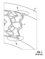
- FIG. 1 shows a stent 1 in a body vessel 2 after implantation with a balloon catheter according to the above-described prior art. Due to the non-physiological straightening in the region of the implanted stent 1, the vessel 2 is bent at the edge of the stent 1. In the process, the stent 1 presses in the outer region 1a of the bent vessel 2 into the vessel wall, as a result of which strong stresses are introduced into the body vessel 2. This leads according to recent studies to increase the Restenoserisikos. In the inner region 1i of the bent vessel, the stent 1 does not abut well against the wall of the vessel 2. As a result, there forms an area with a significantly reduced flow, which also increases the risk of restenosis.
- the present invention is therefore based on the object, a balloon catheter of the type described above, in particular a balloon catheter for introducing a stent into a body vessel, such that the balloon imitates the natural course of the body vessel as well as possible in the expanded state.
- the balloon is shaped so that it assumes a shape in the expanded state, which deviates from the shape of a cylinder, in particular the balloon in the expanded state has a curved or tortuous three-dimensional shape.
- the straightening of the curved vessels is effected by the substantially cylindrical shape of the expanded balloons of a balloon catheter of the prior art. This is avoided by the present invention.
- the shape of the expanded balloon in a balloon catheter according to the invention is not cylindrical. This avoids straightening and the concomitant negative effects of the expansion of the balloon, and the optionally associated implantation of the stent.
- the balloon is shaped such that in the expanded state it is adapted to the shape of the surrounding body vessel, in particular has a curved or tortuous three-dimensional shape.
- the problems described above occur with body vessels whose shape deviates from a straight cylindrical shape, ie the stenosis has formed at a point where the body vessel is bent.
- the balloon catheter according to the invention the balloon can advantageously be expanded here and thus the body vessel can be expanded without the body vessel being straightened.
- the balloon in its expanded state has a curved or tortuous three-dimensional shape corresponding to the shape of the body vessel to be treated.
- the stent is advantageously expanded to a curved or tortuous three-dimensional shape even when a stent is introduced into the body vessel.
- the expanded shape of the stent corresponds to the shape of the body vessel, so that the stent is optimally adapted to the body vessel, the body vessel is not straightened by the introduced stent, but remains in its natural three-dimensional shape. This avoids the previously described effects of the prior art on the inner radius (flow stoppers) and on the outer radius (high stresses in the vessel wall through the stent) and overall reduces the risk of restenosis.
- the balloon is composed of at least two, preferably three, individual segments, wherein at least one segment has a surface which is not a rectangle.
- the balloon is composed of several, at least 2, preferably 3, individual segments, wherein the surface of at least one segment deviates from a rectangular surface. In this way, the balloon can be assembled in such a way that in the expanded state results in a non-cylindrical, curved or tortuous shape.
- a segment is understood to be a piece of a balloon which together with at least two other segments forms the complete balloon.
- a segment is thus a section of the surface of the balloon of any surface.
- a ball such as a football
- the respective contact areas of the balloon with the shaft of the balloon catheter are not understood in the context of the application as segments.
- the contact areas or contact points form a rather conical segment, which can not be exactly defined, and are therefore not regarded as a segment within the scope of this application and within the meaning of this embodiment of the invention.
- the main part of the balloon i. the main shape of the balloon without the contact area of the balloon with the shaft of the balloon catheter composed of at least two, preferably three, individual segments.
- a segment is not a mental division of the balloon into individual sections.
- a balloon catheter of this embodiment of the invention has a balloon which is composed of several segments or individual parts. The individual segments are connected to each other in such a way that the resulting balloon can be acted upon pressure-tight in its intended condition with a fluid.
- At least one segment of the balloon has a non-rectangular surface.
- a segment having a rectangular base corresponds to a cylinder jacket and would accordingly give a cylindrical shape when assembled in three dimensions.
- the deviation from the shape of a rectangle achieves a three-dimensional shape that is different from the shape of a cylinder.
- the bending of the balloon is adjusted by the orientation of the segment edges
- the individual segments are welded or glued together at their abutting edges, wherein the abutting edges overlap at least slightly to ensure welding or gluing.
- welding or gluing the individual segments of the entire balloon is formed.
- the individual segments are thereby pressure-resistant connected to an expandable balloon.
- a balloon catheter of this embodiment of the invention can therefore be produced by cutting individual segments of balloon material. The individual segments are then welded or glued together so that the desired three-dimensional shape of the balloon is formed.
- the connection areas of the balloon with the shaft of the balloon catheter can be realized in various ways in this embodiment of the invention.
- balloon material can be heated and stretched under pressure. This leads in the prior art to a cylindrical balloon. Its edge regions are cut off and glued or welded to the segments of this embodiment of the invention. The edge regions then serve to connect a balloon of this embodiment of the invention with the shaft of the balloon catheter. Alternatively, especially edge regions made of balloon material can be cut to size and connected to the segments of this embodiment of the invention by means of welding or gluing.
- the balloon in the expanded state has a shape consisting of at least two cylindrical sections, the main axes of at least two cylindrical sections an angle greater than 0 ° and less than 180 °, preferably more than 0 ° and less than 90 °, exhibit.
- the main axis of a cylindrical section is understood to mean the axial axis of symmetry of the cylindrical section, i. the axis from the center of the fictional circular base to the center of the fictitious circular top surface of the cylindrical portion.
- the balloon expediently consists of three different segments. Two segments of rectangular area are connected by a third segment of non-rectangular area. The two segments with a rectangular surface form cylindrical sections. The rectangular area of the segments is the lateral surface of the cylinder of this section. The edges of these two segments are joined to the edges of the third segment, which has an area that is not a rectangle. This ensures that the main axes of the two cylindrical sections have an angle which is greater than 0 ° and less than 180 °. That In the expanded state of the balloon of this embodiment, two cylinders are connected via a non-cylindrical segment, which automatically results in a curvature. The two main axes of the cylindrical sections are no longer in line, the balloon as a whole is curved or bent in the expanded state.
- the curvature of this embodiment of the invention corresponds to the curvature and the natural state of the body vessel, in which the balloon for expansion, and in particular for introducing a stent, is introduced.
- the curvature of the expanded balloon can be varied as desired, as well as the angle between the cylindrical segments of the balloon advantageously, the practitioner selects according to the body vessel to be treated between different such balloons.
- the angle between the main axes of the cylindrical (and thus the curvature of the expanded balloon) segments can be made more or less large.
- the radius of curvature in this embodiment of the invention by size, number and angle of the individual segments to each other controllable. If more than a third segment is inserted between the two cylindrical segments, a bend can be described more precisely. The more and the finer the segmented, the less sharp the balloon is in its expanded state. In addition, it is advantageously possible to achieve any desired three-dimensional shape of the balloon in the expanded state via the number and the cutting of the segments.
- the individual segments are connected not only to each other but also to themselves such that a hollow body is formed.
- a segment is preferably connected to itself in such a hollow body that the connection is in line with the connection of the adjacent segment with itself.
- This connecting line is preferably the inner radius of the bent balloon in the expanded state.
- This embodiment of the invention thus describes a balloon catheter with a balloon, which assumes an arbitrary tortuous or curved three-dimensional shape in the expanded state.
- a balloon catheter according to this embodiment of the invention is advantageously selected such that the curved or curved three-dimensional shape of the balloon in the expanded state with the curved or curved three-dimensional shape of the balloon Body vessel matches.
- the practitioner selects the balloon catheter of this embodiment of the invention accordingly from a plurality of such embodiments of the invention with balloons of various sinuous or curved shape and size. The straightening of the body vessel and the associated problems of the prior art are avoided in this embodiment of the invention.
- At least one wire is suitably connected to the material of the balloon such that the compliance of the balloon in the unexpanded state in at least a portion along a first curve on the balloon results from compliance along a second curve different from the balloon.
- the compliance of the balloon means the response of the balloon to a pressure change / pressure increase.
- the balloon is pressurized by means of a fluid inside the balloon and thereby expanded.
- the compliance describes how strong the expansion is at a given pressure.
- a balloon of higher compliance expands more at the same pressure than a balloon with less compliance.
- the compliance is also referred to as compliance. How strong a balloon is in the radial direction, has little direct effect on how well a balloon clings to the vessel. This depends more on the bending stiffness in the expanded state.
- a curve is understood to mean a continuous sequence of points in the geometric space.
- a curve is a straight line on the balloon material.
- a non-cylindrical shape of the balloon of the balloon catheter according to the invention by a targeted, local change in the compliance of the balloon in a predetermined section along a predetermined line.
- a targeted intervention in the compliance of the balloon is made.
- the compliance of the balloon along the line connecting balloon and wire is reduced.
- a wire along a curve with the material of the balloon, preferably in the interior of the balloon, welded or glued or integrated into the balloon material.
- This embodiment of the invention comprises various embodiments.
- the wire may conveniently be the same length as the balloon from proximal to distal exhibit. Alternatively, both shorter and longer wires are possible.
- various forms of wires round wires, profile wires or flat strips as well as straight wires, spiral wires or the like
- materials metallic or non-metallic spring steel, fishing line. The choice of shape, material and length of the wire depends on the desired shape of the balloon in the expanded state as well as on the preferred production.
- the term wire is therefore not limited to metallic wires in the context of this application, but generally describes a wire-like tendon.
- a balloon with high curvature can be achieved by the connection with a short, very stiff wire.
- a short, very stiff wire By closely linking such a wire to the balloon material, for example by welding, the compliance of the balloon along the wire is drastically reduced.
- the balloon expands much less in the expanded state along the wire, whereby a curved three-dimensional shape of the balloon is achieved.
- a plurality of different such wires can be suitably reach any three-dimensional shape of the balloon in the expanded state.
- Similar to the first embodiment of the invention can be selected by the practitioner a balloon catheter with a balloon predetermined three-dimensional shape in the expanded state such that the natural shape of the body vessel is modeled. Accordingly, upon expansion of the balloon, particularly when a stent is inserted into the body vessel, the body vessel is not straightened, thereby avoiding the described disadvantages of the prior art.
- the curve in the unexpanded state of the balloon is a straight line which preferably extends from the proximal to the distal end of the balloon.
- a straight wire is connected to the balloon from proximal to distal over the entire length of the balloon.
- the wire in the balloon interior at several points, preferably along the entire length, with the Balloon material welded or glued.
- the rigidity of the balloon is increased along a straight line from proximal to distal.
- the compliance of the remaining balloon remains unaffected, only along the wire from proximal to distal is the balloon stiffer. Accordingly, the balloon expands significantly less upon expansion by the application of a fluid along that line. As a result, the balloon assumes a curved three-dimensional shape in the expanded state, similar to a banana.
- the wire can be tacked point by point inside the balloon or completely welded or glued.
- the wire may be integrated directly into the balloon material.
- Such an embodiment can be made, for example, by placing and fixing a wire on the inner balloon and inserting this construction into an outer balloon with a correspondingly large proximal neck.
- the straight wire (or particularly tensile inner shaft) is only centered, e.g. linked to the balloon material at the proximal and distal balloon neck.
- the axial stress generated by the balloon internal pressure in the balloon membrane is partially or entirely taken over by the wire.
- the balloon membrane is thus not stretched over the entire circumference in the axial direction. It automatically results in a curved three-dimensional shape similar to a banana.
- the balloon membrane is stretched, on the inside it folds. This particularly preferred form adapts to the three-dimensional turn of the body vessel, so it is "conformable".
- the curve is a helix, wherein along a first straight axis on the balloon from less proximal to less balloon material between two adjacent points of intersection of the first The curve and the helix are located between the adjacent intersections of a second curve on the balloon from proximal to distal and the helix, with the first and second curves being straight in the unexpanded state of the balloon.
- the helix as well as the first and second axes extend from the proximal to the distal end of the balloon, with preferably the first and second axes being on opposite sides of the balloon.
- the turns of a helix are connected to the balloon material, the helix in the simplest case having the same length as the balloon.
- the helix turns are connected along two straight lines with the balloon material. These two straight lines are preferably opposite each other, with more balloon material being located between two adjacent helix turns along one straight line than along the opposite straight line. That along one straight line the balloon material is gathered between two adjacent links similar to a curtain, i.
- the length of the balloon material between 2 adjacent turns of the helical wire is greater than the distance between the two turns. Accordingly, there is more balloon material between the adjacent helical turns than along the opposite straight line. As the balloon is expanded by exposure to the fluid, the balloon may expand more along the straight line with excess material than along the opposite straight line.
- the opposite straight line thus forms a curve with higher rigidity, resulting in a curved three-dimensional shape of the balloon similar to the previous embodiment.
- any curved three-dimensional shapes of the balloon can be realized in the expanded state, depending on how the first and second curves are chosen. Both may extend from proximal to distal or shorter over the entire length of the balloon. Likewise, in some applications, it is convenient if both curves intersect, while in others Use cases can also be arranged in a line. By reducing the compliance of the balloon along the arbitrary first curve by reducing the balloon material between helix turns, curvature is always achieved at these locations. Accordingly, embodiments analogous to the preceding section with more than 2 curves are possible. Likewise, the balloon may conveniently have sections which are provided differently with curves and different helical wires.
- a helical wire is connected to a first wire on at least two adjacent turns of the helix, preferably both wires extending from the proximal to the distal end of the balloon.
- the first wire is straight.
- a helical wire is connected to at least two adjacent turns of the helix with a first wire and at least two adjacent turns of the helix to a second wire.
- the length of the first wire between two adjacent turns of the helix differs from the length of the second wire between two adjacent turns of the helix, preferably both the helical wire and the first and second wires from the proximal to the distal end of the balloon extend.
- the first and the second wire are straight, in particular the first wire on the side opposite the second wire side of the helix is connected to the helical wire.
- both the helical wire and the first and second wires extend from proximal to distal over the entire length of the balloon.
- a helical wire is used as introduced a kind of scaffolding in the balloon interior.
- the compliance of the balloon is deliberately manipulated locally by the introduction of one or more wires connected to the turns of the helical wire.
- the resilience is therefore analogously changed locally and curved or curved three-dimensional shapes of the balloon of the balloon catheter are achieved in the expanded state. Therefore, even in these embodiments of the balloon catheter according to the invention, the straightening of the body vessel can be avoided, in particular when introducing a stent into the body vessel and the associated disadvantages of the prior art.
- this has in the distal region an inner shaft with an inner lumen and an outer second lumen, wherein the second lumen has a flow connection with the balloon interior such that the balloon expands by a fluid in the second lumen and the length of the balloon from proximal to distal is greater than the length of the inner shaft from the proximal end of the balloon to the distal end of the balloon.
- the length of the diameter d from proximal to distal L * (1-r / (r + d)) is greater than the length L of the inner shaft from the proximal end of the balloon to the distal end of the balloon to a radius of curvature r to be able to follow the body vessel.
- the balloon has a greater length from proximal to distal than the inner shaft. This leads to a non-cylindrical shape in the expanded state of the balloon.
- the balloon according to this embodiment of the invention adapts to the tortuous or curved three-dimensional course of the body vessel in which the balloon is expanded. This is ensured by the excess material of the balloon, by its greater length.
- the balloon is longer or it is more balloon material available than actually necessary.
- the shorter inner shaft follows the course of the body vessel on the shortest path, ie it cuts the quasi the Curvatures and bends in the course of the vessel.
- the balloon may follow the natural curved or tortuous three-dimensional course of the body vessel. As a result, a forced straightening of the vessel as with matching length of inner shaft and expanded balloon according to the prior art with the disadvantages described above is avoided.
- the balloon catheter has means with which the size of the difference in length between the balloon and the inner shaft can be variably adjusted.
- the distal end of the balloon is pressure tight and movable over the inner shaft.
- Such a means would be for example a sliding seal.
- a stent is applied to the balloon.
- the application further relates to a system for introducing a stent into a body vessel with a balloon catheter as described in the preceding paragraphs.
- the straightening of the body vessel is avoided by the expansion of the balloon and the introduction of the stent.
- the natural flow conditions of the body vessel before the stenosis are much better restored / maintained.
- the drawbacks described in the prior art flow stoppers in the interior when the stent is inserted, impressions of the stent in the vessel wall in the outer region of the curved body vessel) are avoided and the risk of restenosis correspondingly reduced.
- FIG. 1 has already been described in the description in the description of the prior art.
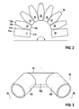
- FIG. 2 schematically shows a balloon 10 which consists of the individual segments 11 to 19, wherein the surfaces of the individual segments are shown.
- the balloon 10 of nine individual parts 11 to 19. In this case, only the segments 11 and 19 have a rectangular surface.
- the remaining Segments 12-18 have a non-rectangular area in the shape of an elongated hexagon.
- the actual balloon 10 is composed of the individual segments 11 to 19, which is described by way of example on the segments 11 and 12.
- segment 11 the two side edges 11a and 11b are connected to each other. This creates a cylindrical hollow body.
- segment 12 the two side edges 12a and 12b are also connected to each other, so that also a hollow body is formed.
- the two segments 11 and 12 are then connected together at their side edges 11c and 12c. Due to the non-rectangular area of segment 12, the shape of the combined segments 11 and 12 deviates from the cylindrical shape. The result is a hollow body with a bend.
- all segments 11 to 19 are connected to each other. In this way, balloon 10 can be formed from the individual segments 11 to 19, so that the balloon 10 in its expanded state has a curved three-dimensional shape in the form of a U. As indicated, the radius of the bend can be predetermined by the number and dimension of the individual segments 12 to 18.
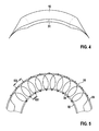
- FIG. 3 shows schematically as a three-dimensional representation of an embodiment of a balloon catheter according to the invention with the simplest form of a balloon 10 of individual segments.
- the balloon 10 consists of three segments 101, 102 and 103 and is shown in its expanded state.
- the balloon 10 consists of two segments 101 and 103 with a rectangular surface and a segment 102 with a non-rectangular surface.
- the non-rectangular area of the central segment 102 achieves a curved three-dimensional shape of the balloon 10 in its expanded state.
- the main axes 21, 22 and 23 of the three cylindrical sections 101, 102 and 103 each have an angle of more than 0 ° and less than 90 ° to each other.
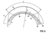
- FIG. 4 schematically shows the balloon 10 of an embodiment of a balloon catheter according to the invention, wherein the balloon 10 has a wire 31.
- the wire 31 extends in this embodiment of the invention as a straight line over the entire length of the balloon 10 from proximal to distal.
- the wire 31 is connected to the balloon material of the balloon 10 (welded, glued or introduced into the balloon material).
- the rigidity of the balloon 10 is changed locally. Specifically, the rigidity along the wire 31 is greatly increased.
- the balloon 10 can expand significantly less when pressurized by the fluid along the wire, so that the balloon 10 in the expanded state has the curved three-dimensional shape of a banana.
- FIG. 5 schematically shows the balloon 10 of an embodiment of a balloon catheter according to the invention, wherein the balloon 10 has three wires 32, 33 and 34.
- the helical wire 34 serves as a framework for the balloon 10.
- the rigidity of the balloon 10 is changed locally by the two wires 32 and 33.
- the two wires 32 and 33 are fixedly connected to the turns of the helical wire 34. The connection is made here by threading through the wires.
- the length 132 and 133 between two adjacent turns of the helical wire 34.
- the length 132 is significantly smaller than 133, whereby the rigidity of the balloon 10 along the wire 32 is significantly increased. Accordingly, the balloon 10 expands less when exposed to a fluid along the wire 32 and similar to the embodiment of the invention
- FIG. 4 a curved three-dimensional shape similar to a banana.
- FIG. 6 schematically shows an embodiment of the invention, in which the length of the inner shaft 40 is smaller than the length of the balloon 10.
- the balloon catheter is shown here in the body vessel 2.
- the balloon catheter has an inner shaft 40 with an inner lumen 41 and an outer shaft 44 with an outer lumen 42.
- the outer lumen 42 is between inner shaft and outer shaft and in fluid communication with the balloon interior 43. Via the outer lumen 42, the balloon 10 is subjected to a fluid and expanded.
- the guide wire 4 is the guide wire 4.
- a tip 3 made of soft radiopaque material.
- the length of the inner shaft 41 from the proximal to the distal end of the balloon 10 is smaller than the balloon length.
- the inner shaft 40 follows the three-dimensional course of the vessel 2 on a direct path. Characterized in that the balloon length is greater than the length of the inner shaft from the proximal to the distal end of the balloon, it is ensured that the balloon in the expanded state, the three-dimensional course of the body vessel 2 adapts.
- the length of the balloon 10 of diameter D from proximal to distal L * (1-r / (r + D)) is greater than the length L of the inner shaft 40 from the proximal end of the balloon 10 to the distal end of the balloon 10 in order to be able to follow a radius of curvature r of the body vessel 2.
- the length L of the balloon 10 is determined without the conical end regions, the diameter D is determined in the expanded state.
Abstract
Description
Die vorliegende Erfindung betrifft einen Ballonkatheter mit einem expandierbaren Ballon zur Behandlung von Stenosen in Körpergefäßen. Ferner betrifft die Erfindung ein System zum Einbringen eines Stents in ein Körpergefäß.The present invention relates to a balloon catheter with an expandable balloon for the treatment of stenoses in body vessels. Furthermore, the invention relates to a system for introducing a stent into a body vessel.
Unter einer Stenose eines Körpergefäßes wird die Verengung des Gefäßdurchmessers verstanden. In Körpergefäßen insbesondere in Arterien, Venen oder ähnlichen Hohlorganen kann es zu Verengungen durch Ablagerungen kommen. Dadurch wird der Fluss durch diese Gefäße eingeschränkt und im schlimmsten Fall unterbunden. Die Körpergefäße werden nicht mehr von den Körperflüssigkeiten durchströmt und stromabwärts gelegenen Regionen nicht mehr bzw. nicht ausreichend versorgt.A stenosis of a body vessel is understood to mean the narrowing of the vessel diameter. In body vessels, especially in arteries, veins or similar hollow organs, constrictions can occur due to deposits. As a result, the flow is restricted by these vessels and in the worst case prevented. The body vessels are no longer traversed by the body fluids and downstream regions no longer or not sufficiently supplied.
Derartige Stenosen in Arterien oder Venen können medizinisch durch ein Angioplastie genanntes Verfahren behandelt werden. Bei einer Angioplastie werden die verengten Gefäße mechanisch wieder aufgeweitet, wodurch der durchströmbare Durchmesser der Körpergefäße wieder erhöht wird. Dabei wird ein Ballonkatheter mit einem expandierbaren Ballon in das Körpergefäß derart geführt, dass sich der expandierbare Ballon an der Stelle der Stenose, d.h. der Verengung, befindet. Durch die Expansion des Ballons wird das Körpergefäß wieder aufgeweitet. Die Gefäßwände werden aufgeweitet, die Ablagerung an die Gefäßwand gedrückt.Such stenoses in arteries or veins can be treated medically by a procedure called angioplasty. In angioplasty, the constricted vessels are widened mechanically again, which increases the permeable diameter of the body vessels again. A balloon catheter with an expandable balloon is guided into the body vessel such that the expandable balloon at the site of the stenosis, i. the constriction, is located. By expanding the balloon, the body vessel is widened again. The vessel walls are widened, the deposit pressed against the vessel wall.
Um die dauerhafte Aufweitung zu gewährleisten, wird dabei häufig eine Gefäßstütze, ein so genannter Stent, in das Köpergefäß an die betroffene Stelle eingebracht. Häufig weisen dabei auch Ballon und/oder Stent eine Beschichtung auf, die über einen vorgegebenen Zeitraum medizinisch wirksame Substanzen abgibt, um die Heilung zu verbessern und/oder die Ausbildung einer erneuten Verengung (Restenose) zu verhindern.In order to ensure the permanent widening, a vascular support, a so-called stent, is often introduced into the body vessel at the affected site. Often, the balloon and / or stent also have a coating which releases medically active substances over a given period of time in order to improve the healing and / or to prevent the formation of a new constriction (restenosis).
Unter der Behandlung einer Stenose in einem Körpergefäß wird daher im Rahmen dieser Anmeldung, die Behandlung einer Verengung in einem Körpergefäß, insbesondere in einer Arterie oder Vene, verstanden, wobei ein Ballonkatheter in das betroffene Körpergefäß eingebracht wird. Die Behandlung umfasst dabei das Aufweiten der Verengung durch einen expandierbaren Ballon des Ballonkatheters mit oder ohne Einbringen eines Stents mit oder ohne Beschichtung des Ballons und/oder Stents.For the purposes of this application, the treatment of a stenosis in a body vessel is understood to mean the treatment of a narrowing in a body vessel, in particular in an artery or vein, whereby a balloon catheter is introduced into the affected body vessel. The treatment includes expanding the constriction through an expandable balloon of the balloon catheter with or without introduction of a stent with or without coating the balloon and / or stent.
Unter einem Stent wird im Rahmen der Anmeldung ein Metall oder Polymergeflecht verstanden, welches in das Körpergefäß eingebracht werden kann. Der Stent bewirkt dabei zumindest über eine vorgegebene Zeit eine Stützung des Körpergefäßes. Der Stent kann im Rahmen dieser Anmeldung sowohl permanent als auch biologisch abbaubar oder degradierbar sein.In the context of the application, a stent is understood as meaning a metal or polymer braid which can be introduced into the body vessel. The stent causes at least over a predetermined time a support of the body vessel. For the purposes of this application, the stent may be both permanent and biodegradable or degradable.
Im Stand der Technik sind verschiedene Ballonkatheter mit expandierbaren Ballon bekannt. Im Rahmen dieser Anmeldung werden die Begriffe Expansion/expandieren, Dilatation/dilatieren und Aufdehnung/aufdehnen des Ballons als synonym betrachtet, wobei im Rahmen dieser Anmeldung der Begriff Expansion/expandieren verwendet wird.Various balloon catheters with expandable balloon are known in the art. In the context of this application, the terms expansion / expansion, dilation / dilation and expansion / expansion of the balloon are considered to be synonymous, the term expansion / expansion being used in the context of this application.
Die im Stand der Technik bekannten Ballonkatheter weisen alle die folgenden wesentlichen Bestandteile auf: einen Ballon, eine Spitze, ein inneres Lumen für einen Führungsdraht und ein Lumen zur Beaufschlagung des Ballons mit einem Fluid sowie die entsprechenden Verbindungsmöglichkeiten mit einer Druckquelle für das Fluid.The balloon catheters known in the prior art all comprise the following essential components: a balloon, a tip, an inner lumen for a guide wire, and a lumen for impinging the balloon with a fluid and the corresponding connection possibilities with a pressure source for the fluid.
Unter einem Lumen wird im Rahmen dieser Anmeldung der freie durchströmbare Querschnitt eines Hohlkörpers verstanden. Im einfachsten Fall eines zylindrischen Rohrs ergibt sich das Lumen entsprechend als innerer Querschnitt des Rohres.In the context of this application, a lumen is understood as meaning the free flow-through cross section of a hollow body. In the simplest case of a cylindrical tube, the lumen correspondingly results as the inner cross section of the tube.
Ein Ballonkatheter weist einen Schaft auf, in dessen distalen Bereich sich der expandierbare Ballon befindet. Im proximalen Bereich bzw. am proximalen Ende des Ballonkatheters befinden sich die Verbindungsmöglichkeiten (zumeist ein oder mehrere Luer Lock Anschlüsse) für die Zuführung des Führungsdrahtes bzw. für das Fluid zur Beaufschlagung des Ballons.A balloon catheter has a shaft in the distal region of which the expandable balloon is located. In the proximal region or at the proximal end of the balloon catheter are the connection options (usually one or more Luer lock connections) for the supply of the guide wire or for the fluid for applying the balloon.
Im Rahmen dieser Anmeldung wird unter dem proximalen Ende eines Ballonkatheters das Ende verstanden, welches in der Hand des Behandlers außerhalb des Körpers/des Körpergefäßes liegt. Das distale Ende eines Ballonkatheters ist entsprechend die in das Körpergefäß geführte Spitze des Ballonkatheters. Entsprechend sind die Lagebezeichnungen proximal (näher zum Behandler) und distal (näher zur im Körpergefäß befindlichen Spitze des Ballonkatheters) zu verstehen.In the context of this application, the term proximal end of a balloon catheter is understood to mean the end which lies outside the body / body vessel in the hand of the practitioner. The distal end of a balloon catheter is correspondingly the tip of the balloon catheter guided into the body vessel. Correspondingly, the location designations are to be understood as proximal (closer to the practitioner) and distal (closer to the tip of the balloon catheter located in the body vessel).
Zumeist wurde ein Führungsdraht, welcher mit Röntgenmarkern ausgestattet oder komplett sichtbar für Röntgenstrahlung ist, schon im Körpergefäß platziert. Über diesen Führungsdraht wird der Ballonkatheter mit der Spitze voran eingeführt. Die Spitze des Ballonkatheters ist dabei sehr flexibel, um Verletzungen der Wände des Körpergefäßes zu vermeiden, und derart beschichtet, dass ein möglichst reibungsfreies Gleiten im Körpergefäß ermöglicht wird. Zusätzlich ist sie sichtbar bei Röntgenstrahlung. Der Führungsdraht wird im inneren Lumen des Ballonkatheters geführt.In most cases, a guidewire, which is equipped with X-ray markers or completely visible for X-rays, has already been placed in the body vessel. About this guide wire, the balloon catheter is inserted with the tip first. The tip of the balloon catheter is very flexible in order to avoid injuries to the walls of the body vessel, and coated in such a way that frictionless as possible sliding in the body vessel is made possible. In addition, it is visible with X-rays. The guidewire is guided in the inner lumen of the balloon catheter.
Der Ballonkatheter wird mit Hilfe des Führungsdrahtes so platziert, dass der Ballon an der Stelle der Stenose im Gefäß ist. Um eine sichere Platzierung zu gewährleisten, weißt der Schaft und/oder der Ballon entsprechende Röntgenmarkierungen auf. Dann wird der Ballon über das entsprechende Lumen mit einem Fluid beaufschlagt und expandiert. Die Ablagerungen werden dabei an die Gefäßwand gedrückt und das Gefäß erweitert. Der Ballon wird dabei mit einem Druck von 6 bar (4 bis 8 bar, Niederdruckexpansion) oder bei einer Hochdruckexpansion mit einem Druck von mehr als 16 bis 18 bar bzw. bis zu 40 bar beaufschlagt.The balloon catheter is placed using the guide wire so that the balloon is in place at the site of the stenosis. To ensure a secure placement, the shaft and / or the balloon have corresponding x-ray markings. Then, the balloon is acted upon by the corresponding lumen with a fluid and expanded. The deposits are thereby pressed against the vessel wall and expanded the vessel. The balloon is thereby subjected to a pressure of 6 bar (4 to 8 bar, low pressure expansion) or in a high-pressure expansion with a pressure of more than 16 to 18 bar or up to 40 bar.
Je nach Anordnung der Lumen des Ballonkatheters wird dabei im Stand der Technik zwischen einem Over-the-Wire System, einem Rapid-Exchange System oder einem Fixed-Wire System unterschieden. Bei einem Over-the-Wire System sind das innere Lumen für den Führungsdraht und das Lumen zur Fluidbeaufschlagung des Ballons koaxial angeordnet. Im inneren Schaft mit dem inneren Lumen befindet sich der Führungsdraht, der äußere Schaft mit größeren Innen- und Außendurchmesser bildet das Lumen zur Beaufschlagung des Ballons. Beide Lumen erstrecken sich vom proximalen bis zum distalen Ende des Ballonkatheters. Bei einem Rapid-Exchange System (teilweise auch als Monorail System oder Single-Operator System bekannt) ist das Lumen für den Führungsdraht nicht bis zum proximalen Ende des Ballonkatheters durchgehend, sondern nur im distalen Abschnitt des Ballonkatheters (rund 20cm). Dies erlaubt einen schnellen Austausch des Ballonkatheters und die Verwendung kürzerer Führungsdrähte. Das Lumen für den Führungsdraht und das Lumen zur Fluidbeaufschlagung des Ballons können dabei koaxial oder parallel angeordnet sein. Fixed-Wire Ballonkatheter haben einen Führungsdraht, der in ihrem Lumen fest positioniert ist.Depending on the arrangement of the lumen of the balloon catheter, a distinction is made in the prior art between an over-the-wire system, a rapid-exchange system or a fixed-wire system. In an over-the-wire system, the inner lumen for the guidewire and the lumen for fluid pressurization of the balloon are coaxially arranged. In the inner shaft with the inner lumen is the guide wire, the outer shaft with larger inner and outer diameter forms the lumen for loading the balloon. Both lumens extend from the proximal to the distal end of the balloon catheter. In a rapid exchange system (sometimes known as a monorail system or single-operator system), the lumen for the guidewire is not continuous to the proximal end of the balloon catheter, but only in the distal portion of the balloon catheter (about 20 cm). This allows a quick replacement of the balloon catheter and the use of shorter guidewires. The lumen for the guide wire and the lumen for fluid loading of the balloon can be arranged coaxially or in parallel. Fixed-Wire Balloon Catheters have a guidewire that is firmly positioned in their lumen.
Im Rahmen dieser Anmeldung wird das Lumen für den Führungsdraht immer als inneres Lumen (und entsprechend innerer Schaft) und das Lumen zur Fluidbeaufschlagung des Ballons immer als äußeres Lumen bezeichnet, unabhängig von koaxialer oder paralleler Anordnung. Das Innere, mit Fluid befüllbar und unter Druck setzbare, des Ballons wird im Rahmen dieser Anmeldung als Ballonlumen oder Balloninnere bezeichnet.In the context of this application, the guidewire lumen will always be referred to as the inner lumen (and corresponding inner shaft) and the lumen for fluid delivery to the balloon will always be referred to as the outer lumen, independently of coaxial or parallel disposition. The interior, fluid-fillable and pressurizable, of the balloon is referred to in this application as a balloon lumen or balloon interior.
Werden derartige Ballonkatheter nach dem Stand der Technik zur Implantierung von Stents in Körpergefäßen verwendet, wird auf den expandierbaren Ballon ein Stent aufgebracht. Dies wird im Stand der Technik auch als crimpen bezeichnet. Mit der Expansion des Ballons wird dann der Stent aufgedehnt und gegen die Gefäßwand gepresst. Der Stent ist dabei aus einem derartigen Material, dass er nach der Expansion die dabei erhaltene Form behält.When such prior art balloon catheters are used to implant stents in body vessels, a stent is applied to the expandable balloon. This is also referred to in the art as crimping. With the expansion of the balloon, the stent is then expanded and pressed against the vessel wall. The stent is made of such a material that it retains the shape obtained after expansion.
Im Stand der Technik sind unterschiedliche Ballone und Stents in den verschiedensten Größen bekannt. Als Standardgröße wird im Stand der Technik beispielsweise ein Ballon verstanden, der für die koronare Anwendung einen Durchmesser von 3.0 mm im expandierten Zustand und eine Länge von 20 mm aufweist. Der zugehörige Stent weist in seinem expandierten Zustand analoge Dimensionen auf.In the prior art different balloons and stents in various sizes are known. The standard size in the prior art, for example, a balloon understood that for coronary use has a diameter of 3.0 mm in the expanded state and a length of 20 mm. The associated stent has analogous dimensions in its expanded state.
Der nicht expandierte Ballon wird auf den inneren Schaft gefaltet, der Stent gegebenenfalls darauf gepresst, so dass das sich im nicht expandierten Zustand eine möglichst kleinerThe unexpanded balloon is folded onto the inner shaft, the stent optionally pressed thereon, so that in the unexpanded state as small as possible
Durchmesser ergibt, um den Ballonkatheter möglichst einfach und störungsfrei in das Körpergefäß an die Stelle der Stenose zu führen. Bei Expansion nehmen sowohl der Ballon als auch gegebenenfalls der darauf befestigte Stent eine im Wesentlichen zylindrische Form an.Diameter results in the balloon catheter as simple and trouble-free to lead into the body vessel at the site of the stenosis. Upon expansion, both the balloon and, optionally, the attached stent assume a substantially cylindrical shape.
Dies führt bei gekrümmten Körpergefäßen zu Problemen, insbesondere wenn die Stenose an einer Krümmung des Körpergefäßes auftritt. In diesem Fall führt die Expansion des Ballons zu einer unerwünschten und unphysiologischen Begradigung des Körpergefäßes bedingt durch die hohe Biegesteifigkeit des inflatierten Ballons, die insbesondere bei Einsatz eines permanenten Stents erhalten bleibt. Wird ein Stent in ein derart gekrümmtes Gefäß eingebracht, wird der Teil des Gefäßes, der unmittelbar vom Stent gestützt wird, begradigt. Die benachbarten Gefäßabschnitte behalten im Wesentlichen ihre vorherige Form, so dass es an den Rändern des Stents zu einem Abknicken des Körpergefäßes kommt, wie in
Der vorliegenden Erfindung liegt daher die Aufgabe zugrunde, einen Ballonkatheter der vorangehend geschilderten Art, insbesondere einen Ballonkatheter zum Einbringen eines Stents in ein Körpergefäß, derart auszugestalten, dass der Ballon im expandierten Zustand den natürlichen Verlauf des Körpergefäßes möglichst gut nachbildet. Ein Begradigen des Körpergefäßes durch den expandierten Ballon, insbesondere durch einen Stent, der mittels expandierten Ballons an die Gefäßwand gepresst wird, soll bei der vorliegenden Erfindung vermieden werden.The present invention is therefore based on the object, a balloon catheter of the type described above, in particular a balloon catheter for introducing a stent into a body vessel, such that the balloon imitates the natural course of the body vessel as well as possible in the expanded state. A straightening of the body vessel by the expanded balloon, in particular by a stent, which is pressed by means of expanded balloons to the vessel wall to be avoided in the present invention.
Die vorliegende Aufgabe wird durch die Merkmale des unabhängigen Anspruches 1 gelöst. Weitere vorteilhafte Ausgestaltungen werden in den abhängigen Ansprüchen aufgeführt.The present object is solved by the features of independent claim 1. Further advantageous embodiments are listed in the dependent claims.
Erfindungsgemäß wird der Ballon derart ausgeformt ist, dass er im expandierten Zustand eine Form einnimmt, die von der Form eines Zylinders abweicht, insbesondere der Ballon im expandierten Zustand eine gebogene oder gewundene dreidimensionale Form aufweist. Hauptsächlich erfolgt die Begradigung der gekrümmten Gefäße durch die im Wesentlichen zylindrische Form der expandierten Ballone eines Ballonkatheters nach dem Stand der Technik. Dies wird durch die vorliegende Erfindung vermieden. Die Form des expandierten Ballons bei einem erfindungsgemäßen Ballonkatheter ist nicht zylindrisch. Dadurch werden die Begradigung und die damit einhergehenden negativen Effekte durch die Expansion des Ballons, und die optional damit verbundene Implantation des Stents, vermieden.According to the invention, the balloon is shaped so that it assumes a shape in the expanded state, which deviates from the shape of a cylinder, in particular the balloon in the expanded state has a curved or tortuous three-dimensional shape. Mainly, the straightening of the curved vessels is effected by the substantially cylindrical shape of the expanded balloons of a balloon catheter of the prior art. This is avoided by the present invention. The shape of the expanded balloon in a balloon catheter according to the invention is not cylindrical. This avoids straightening and the concomitant negative effects of the expansion of the balloon, and the optionally associated implantation of the stent.
Unter expandierten Zustand des Ballons wird im Rahmen der Anmeldung verstanden, dass der Ballon an seiner bestimmungsgemäßen Position im Körpergefäß mit einem Fluid beaufschlagt und expandiert wurde. Dies umfasst sowohl die vorangehend beschriebenen Niederdruckexpansion als auch die Hochdruckexpansion.Under expanded state of the balloon is understood in the context of the application that the balloon was acted upon at its intended position in the body vessel with a fluid and expanded. This includes both the low pressure expansion described above and the high pressure expansion.
Vorteilhafterweise ist der Ballon derart ausgeformt, dass er im expandierten Zustand der Form des umgebenden Körpergefäßes angepasst ist, insbesondere eine gebogene oder gewundene dreidimensionale Form aufweist. Die vorausgehend geschilderten Probleme treten bei Körpergefäßen auf, deren Form von einer geraden zylindrischen Form abweicht, d.h. sich die Stenose an einer Stelle gebildet hat, wo das Körpergefäß gebogen ist. Durch den erfindungsgemäßen Ballonkatheter kann hier vorteilhafterweise der Ballon expandiert und damit das Körpergefäße aufgedehnt werden, ohne dass das Körpergefäß begradigt wird. Der Ballon hat in seinem expandierten Zustand eine gebogene oder gewundene dreidimensionale Form, die der Form des zu behandelnden Körpergefäßes entspricht. Dadurch wird vorteilhafterweise auch bei Einbringen eines Stents in das Körpergefäß der Stent auf eine gebogene oder gewundene dreidimensionale Form aufgedehnt. Die aufgedehnte Form des Stents entspricht der Form des Körpergefäßes, so dass der Stent optimal dem Körpergefäß angepasst ist, das Körpergefäß durch den eingebrachten Stent nicht begradigt wird, sondern in seiner natürlichen dreidimensionalen Form bleibt. Dadurch werden die vorausgehend geschilderten Effekte des Standes der Technik am Innenradius (Strömungstotstellen) und am Außenradius (starke Spannungen in der Gefäßwand durch den Stent) vermieden und insgesamt das Risiko einer Restenose gesenkt.Advantageously, the balloon is shaped such that in the expanded state it is adapted to the shape of the surrounding body vessel, in particular has a curved or tortuous three-dimensional shape. The problems described above occur with body vessels whose shape deviates from a straight cylindrical shape, ie the stenosis has formed at a point where the body vessel is bent. By means of the balloon catheter according to the invention, the balloon can advantageously be expanded here and thus the body vessel can be expanded without the body vessel being straightened. The balloon in its expanded state has a curved or tortuous three-dimensional shape corresponding to the shape of the body vessel to be treated. As a result, the stent is advantageously expanded to a curved or tortuous three-dimensional shape even when a stent is introduced into the body vessel. The expanded shape of the stent corresponds to the shape of the body vessel, so that the stent is optimally adapted to the body vessel, the body vessel is not straightened by the introduced stent, but remains in its natural three-dimensional shape. This avoids the previously described effects of the prior art on the inner radius (flow stoppers) and on the outer radius (high stresses in the vessel wall through the stent) and overall reduces the risk of restenosis.
Gemäß einer vorteilhaften Ausgestaltung der Erfindung ist der Ballon aus mindestens zwei, bevorzugt drei, einzelnen Segmenten zusammengesetzt, wobei mindestens ein Segment eine Fläche aufweist, die kein Rechteck ist. Gemäß dieser Ausgestaltung der Erfindung wird der Ballon aus mehreren, mindestens 2, bevorzugt 3, einzelnen Segmenten zusammengesetzt, wobei die Fläche mindestens eines Segmentes von einer Rechteckfläche abweicht. Auf diese Weise lässt sich der Ballon derart zusammensetzten, dass sich im expandierten Zustand eine nicht zylindrische, gebogene oder gewundene Form ergibt.According to an advantageous embodiment of the invention, the balloon is composed of at least two, preferably three, individual segments, wherein at least one segment has a surface which is not a rectangle. According to this embodiment of the invention, the balloon is composed of several, at least 2, preferably 3, individual segments, wherein the surface of at least one segment deviates from a rectangular surface. In this way, the balloon can be assembled in such a way that in the expanded state results in a non-cylindrical, curved or tortuous shape.
Unter einem Segment wird im Rahmen der Erfindung ein Stück eines Ballons verstanden, welches mit mindestens zwei anderen Segmenten zusammen den vollständigen Ballon bildet. Ein Segment ist somit ein Teilstück der Oberfläche des Ballons beliebiger Fläche. Eine Kugel, wie beispielsweise ein Fußball, lässt sich aus einer Vielzahl von Sechsecken und Fünfecken zusammensetzen. Im Rahmen dieser Anmeldung würde man diese Sechsecke und Fünfecke als Segmente mit einer sechseckigen bzw. fünfeckigen nicht rechteckigen Fläche verstehen. Die jeweiligen Kontaktbereiche des Ballons mit dem Schaft des Ballonkatheters werden im Rahmen der Anmeldung nicht als Segmente verstanden. Die Kontaktbereiche oder Kontaktstellen bilden ein eher kegelförmiges Segment, das nicht exakt definierbar ist, und werden daher im Rahmen dieser Anmeldung und im Sinne dieser Ausgestaltung der Erfindung nicht als Segment gesehen. Im Rahmen dieser Ausgestaltung ist der Hauptteil des Ballons, d.h. die hauptsächliche Form des Ballons ohne den Kontaktbereich des Ballons mit dem Schaft des Ballonkatheters aus mindestens zwei, bevorzugt drei, einzelnen Segmenten zusammengesetzt.In the context of the invention, a segment is understood to be a piece of a balloon which together with at least two other segments forms the complete balloon. A segment is thus a section of the surface of the balloon of any surface. A ball, such as a football, can be composed of a variety of hexagons and pentagons. In the context of this application, one would understand these hexagons and pentagons as segments with a hexagonal or pentagonal non-rectangular area. The respective contact areas of the balloon with the shaft of the balloon catheter are not understood in the context of the application as segments. The contact areas or contact points form a rather conical segment, which can not be exactly defined, and are therefore not regarded as a segment within the scope of this application and within the meaning of this embodiment of the invention. In the context of this embodiment, the main part of the balloon, i. the main shape of the balloon without the contact area of the balloon with the shaft of the balloon catheter composed of at least two, preferably three, individual segments.
Ein Segment ist im Rahmen der Erfindung keine gedankliche Teilung des Ballons in einzelne Abschnitte. Ein Ballonkatheter dieser Ausgestaltung der Erfindung weist einen Ballon auf, der aus mehreren Segmenten oder Einzelteilen zusammengesetzt ist. Die einzelnen Segmente werden dabei derart miteinander verbunden, dass der entstehende Ballon in seinem bestimmungsgemäßen Zustand mit einem Fluid druckdicht beaufschlagt werden kann.Within the scope of the invention, a segment is not a mental division of the balloon into individual sections. A balloon catheter of this embodiment of the invention has a balloon which is composed of several segments or individual parts. The individual segments are connected to each other in such a way that the resulting balloon can be acted upon pressure-tight in its intended condition with a fluid.
In dieser Ausgestaltung der Erfindung hat mindestens ein Segment des Ballons eine nicht rechteckige Fläche. Ein Segment mit einer rechteckigen Grundfläche entspricht einem Zylindermantel und würde entsprechend dreidimensional zusammengesetzt eine zylindrische Form ergeben. Durch die Abweichung von der Form eines Rechteckes wird eine dreidimensionale Form erreicht, die sich von der Form eines Zylinders unterscheidet. Die Biegung des Ballons wird durch die Orientierung der Segmentkanten eingestelltIn this embodiment of the invention, at least one segment of the balloon has a non-rectangular surface. A segment having a rectangular base corresponds to a cylinder jacket and would accordingly give a cylindrical shape when assembled in three dimensions. The deviation from the shape of a rectangle achieves a three-dimensional shape that is different from the shape of a cylinder. The bending of the balloon is adjusted by the orientation of the segment edges
Bevorzugt sind die einzelnen Segmente an ihren Stoßkanten miteinander verschweißt oder verklebt, wobei die Stoßkanten zumindest leicht überlappen, um ein Verschweißen bzw. Verkleben zu gewährleisten. Durch das Verschweißen oder Verkleben der einzelnen Segmente wird der gesamte Ballon gebildet. Die einzelnen Segmente sind dadurch druckfest zu einem expandierbaren Ballon verbunden.Preferably, the individual segments are welded or glued together at their abutting edges, wherein the abutting edges overlap at least slightly to ensure welding or gluing. By welding or gluing the individual segments of the entire balloon is formed. The individual segments are thereby pressure-resistant connected to an expandable balloon.
Ein Ballonkatheter dieser Ausgestaltung der Erfindung lässt sich daher dadurch herstellen, dass einzelne Segmente aus Ballonmaterial zugeschnitten werden. Die einzelnen Segmente werden dann derart miteinander verschweißt oder verklebt, dass die gewünschte dreidimensionale Form des Ballons entsteht. Die Verbindungsbereiche des Ballons mit dem Schaft des Ballonkatheters können in dieser Ausgestaltung der Erfindung auf verschiedene Weise realisiert werden.A balloon catheter of this embodiment of the invention can therefore be produced by cutting individual segments of balloon material. The individual segments are then welded or glued together so that the desired three-dimensional shape of the balloon is formed. The connection areas of the balloon with the shaft of the balloon catheter can be realized in various ways in this embodiment of the invention.
Zum einen kann wie im Stand der Technik Ballonmaterial erwärmt und unter Druck gedehnt werden. Dies führt im Stand der Technik zu einem zylindrischen Ballon. Dessen Randbereiche werden abgeschnitten und mit den Segmenten dieser Ausführungsform der Erfindung verklebt oder verschweißt. Die Randbereiche dienen dann der Verbindung eines Ballons dieser Ausführungsform der Erfindung mit dem Schaft des Ballonkatheters. Alternativ können auch speziell Randbereiche aus Ballonmaterial zugeschnitten werden und mit den Segmenten dieser Ausführungsform der Erfindung mittels verschweißen oder verkleben verbunden werden.On the one hand, as in the prior art, balloon material can be heated and stretched under pressure. This leads in the prior art to a cylindrical balloon. Its edge regions are cut off and glued or welded to the segments of this embodiment of the invention. The edge regions then serve to connect a balloon of this embodiment of the invention with the shaft of the balloon catheter. Alternatively, especially edge regions made of balloon material can be cut to size and connected to the segments of this embodiment of the invention by means of welding or gluing.
Vorteilhafterweise weist der Ballon im expandierten Zustand eine Form auf, die aus mindestens zwei zylinderförmigen Abschnitten besteht, wobei die Hauptachsen von mindestens zwei zylinderförmigen Abschnitten einen Winkel mehr als 0° und weniger als 180°, bevorzugt mehr als 0° und weniger als 90°, aufweisen.Advantageously, the balloon in the expanded state has a shape consisting of at least two cylindrical sections, the main axes of at least two cylindrical sections an angle greater than 0 ° and less than 180 °, preferably more than 0 ° and less than 90 °, exhibit.
Unter der Hauptachse eines zylinderförmigen Abschnittes wird in dieser Ausgestaltung der Erfindung die axiale Symmetrieachse des zylinderförmigen Abschnittes verstanden, d.h. die Achse vom Mittelpunkt der fiktiven kreisförmigen Grundfläche zum Mittelpunkt der fiktiven kreisförmigen Deckfläche des zylindrischen Abschnittes.In this embodiment of the invention, the main axis of a cylindrical section is understood to mean the axial axis of symmetry of the cylindrical section, i. the axis from the center of the fictional circular base to the center of the fictitious circular top surface of the cylindrical portion.
Dies ist die einfachste und zweckmäßigste Realisierung dieser Ausführungsform der Erfindung. Der Ballon besteht zweckmäßigerweise aus drei verschiedenen Segmenten. Zwei Segmente mit rechteckiger Fläche werden über ein drittes Segment mit nicht rechteckiger Fläche verbunden. Die beiden Segmente mit rechteckiger Fläche bilden zylinderförmige Abschnitte. Die rechteckige Fläche der Segmente ist die Mantelfläche des Zylinders dieses Abschnittes. Die Kanten dieser beiden Segmente werden mit den Kanten des dritten Segmentes verbunden, welches eine Fläche aufweist, die kein Rechteck ist. Dadurch wird erreicht, dass die Hauptachsen der beiden zylindrischen Abschnitte einen Winkel aufweisen, welcher größer als 0° und kleiner als 180° ist. D.h. im expandierten Zustand des Ballons dieser Ausgestaltung werden zwei Zylinder über ein nicht zylindrisches Segment verbunden, wodurch sich automatisch eine Krümmung ergibt. Die beiden Hauptachsen der zylindrischen Abschnitte sind nicht mehr in einer Linie, der Ballon insgesamt ist im expandierten Zustand gekrümmt bzw. gebogen.This is the simplest and most practical realization of this embodiment of the invention. The balloon expediently consists of three different segments. Two segments of rectangular area are connected by a third segment of non-rectangular area. The two segments with a rectangular surface form cylindrical sections. The rectangular area of the segments is the lateral surface of the cylinder of this section. The edges of these two segments are joined to the edges of the third segment, which has an area that is not a rectangle. This ensures that the main axes of the two cylindrical sections have an angle which is greater than 0 ° and less than 180 °. That In the expanded state of the balloon of this embodiment, two cylinders are connected via a non-cylindrical segment, which automatically results in a curvature. The two main axes of the cylindrical sections are no longer in line, the balloon as a whole is curved or bent in the expanded state.
Die Krümmung dieser Ausgestaltung der Erfindung entspricht dabei der Krümmung und dem natürlichen Zustand des Körpergefäßes, in welches der Ballon zur Expansion, und insbesondere zum Einbringen eines Stents, eingebracht wird. Die Krümmung des expandierten Ballons kann dabei ebenso wie der Winkel zwischen den zylindrischen Segmenten des Ballons vorteilhafterweise beliebig variiert werden, wobei der Behandler entsprechend dem zu behandelnden Körpergefäß zwischen verschiedenen derartigen Ballonen auswählt.The curvature of this embodiment of the invention corresponds to the curvature and the natural state of the body vessel, in which the balloon for expansion, and in particular for introducing a stent, is introduced. The curvature of the expanded balloon can be varied as desired, as well as the angle between the cylindrical segments of the balloon advantageously, the practitioner selects according to the body vessel to be treated between different such balloons.
Je nach Zuschnitt des dritten Segmentes zwischen den zylindrischen Segmenten lässt sich der Winkel zwischen den Hauptachsen der zylindrischen (und somit die Krümmung des expandierten Ballons) Segmente mehr oder weniger groß gestalten. Der Radius der Krümmung ist in dieser Ausgestaltung der Erfindung durch Größe, Zahl und Winkel der einzelnen Segmente zueinander steuerbar. Wird mehr als ein drittes Segment zwischen die beiden zylindrischen Segmente eingefügt, lässt sich eine Biegung feiner/ genauer beschreiben. Je mehr und je feiner segmentiert, umso weniger scharf ist der Ballon im expandierten Zustand gebogen. Zusätzlich lässt sich vorteilhafterweise über die Zahl und den Zuschnitt der Segmente jede beliebige dreidimensionale Form des Ballons im expandierten Zustand erreichen.Depending on the cut of the third segment between the cylindrical segments, the angle between the main axes of the cylindrical (and thus the curvature of the expanded balloon) segments can be made more or less large. The radius of curvature in this embodiment of the invention by size, number and angle of the individual segments to each other controllable. If more than a third segment is inserted between the two cylindrical segments, a bend can be described more precisely. The more and the finer the segmented, the less sharp the balloon is in its expanded state. In addition, it is advantageously possible to achieve any desired three-dimensional shape of the balloon in the expanded state via the number and the cutting of the segments.
Zweckmäßigerweise werden die einzelnen Segmente nicht nur miteinander sondern auch mit sich selbst derart verbunden, dass ein Hohlkörper entsteht. Dabei wird bevorzugt ein Segment mit sich selbst derart zu einem Hohlkörper verbunden, dass die Verbindung in einer Linie mit der Verbindung des benachbarten Segmentes mit sich selbst liegt. Diese Verbindungslinie ist bevorzugt der innere Radius des gebogenen Ballons im expandierten Zustand.Conveniently, the individual segments are connected not only to each other but also to themselves such that a hollow body is formed. In this case, a segment is preferably connected to itself in such a hollow body that the connection is in line with the connection of the adjacent segment with itself. This connecting line is preferably the inner radius of the bent balloon in the expanded state.
Diese Ausgestaltung der Erfindung beschreibt somit einen Ballonkatheter mit einem Ballon, der im expandierten Zustand eine beliebige gewundene oder gebogene dreidimensionale Form einnimmt. Bei der Behandlung einer Stenose in einem Körpergefäß, insbesondere beim Einbringen eines Stents in dieses Körpergefäß, wird ein Ballonkatheter nach dieser Ausgestaltung der Erfindung vorteilhafterweise derart ausgewählt, dass die gekrümmte oder gebogene dreidimensionale Form des Ballons im expandierten Zustand mit der gekrümmten oder gebogenen dreidimensionalen Form des Körpergefäßes übereinstimmt. Der Behandler wählt dabei den Ballonkatheter dieser Ausgestaltung der Erfindung entsprechend aus mehreren derartigen Ausgestaltungen der Erfindungen mit Ballonen verschiedenster gewundener oder gebogener Form und Größe aus. Die Begradigung des Körpergefäßes und die damit einhergehenden Probleme des Standes der Technik werden in dieser Ausgestaltung der Erfindung vermieden.This embodiment of the invention thus describes a balloon catheter with a balloon, which assumes an arbitrary tortuous or curved three-dimensional shape in the expanded state. When treating a stenosis in a body vessel, in particular when introducing a stent into this body vessel, a balloon catheter according to this embodiment of the invention is advantageously selected such that the curved or curved three-dimensional shape of the balloon in the expanded state with the curved or curved three-dimensional shape of the balloon Body vessel matches. The practitioner selects the balloon catheter of this embodiment of the invention accordingly from a plurality of such embodiments of the invention with balloons of various sinuous or curved shape and size. The straightening of the body vessel and the associated problems of the prior art are avoided in this embodiment of the invention.
In einer anderen Ausgestaltung der Erfindung ist mindestens ein Draht mit dem Material des Ballons in geeigneter Weise derart verbunden, dass sich die Nachgiebigkeit des Ballons im nicht expandierten Zustand in mindestens einem Abschnitt entlang einer ersten Kurve auf dem Ballon von der Nachgiebigkeit entlang einer zweiten Kurve auf dem Ballon unterscheidet.In another embodiment of the invention, at least one wire is suitably connected to the material of the balloon such that the compliance of the balloon in the unexpanded state in at least a portion along a first curve on the balloon results from compliance along a second curve different from the balloon.
Unter der Nachgiebigkeit des Ballons wird im Rahmen dieser Anmeldung und dieser Ausgestaltung der Erfindung die Reaktion des Ballons bei Druckänderung/Druckerhöhung bezeichnet. Der Ballon wird mittels eines Fluids im Balloninneren unter Druck gesetzt und dadurch expandiert. Die Nachgiebigkeit beschreibt, wie stark die Expansion bei vorgegebenem Druck ist. Ein Ballon höherer Nachgiebigkeit dehnt sich bei gleichem Druck stärker aus als ein Ballon mit geringerer Nachgiebigkeit. In der englischen Literatur wird die Nachgiebigkeit auch als Compliance bezeichnet. Wie stark ein Ballon in radialer Richtung nachgiebig ist, hat wenig direkten Einfluss, wie gut sich ein Ballon an das Gefäß anschmiegt. Dies hängt eher von der Biegesteifigkeit im expandierten Zustand ab.In the context of this application and this embodiment of the invention, the compliance of the balloon means the response of the balloon to a pressure change / pressure increase. The balloon is pressurized by means of a fluid inside the balloon and thereby expanded. The compliance describes how strong the expansion is at a given pressure. A balloon of higher compliance expands more at the same pressure than a balloon with less compliance. In the English literature, the compliance is also referred to as compliance. How strong a balloon is in the radial direction, has little direct effect on how well a balloon clings to the vessel. This depends more on the bending stiffness in the expanded state.
Unter einer Kurve wird im Rahmen der Erfindung eine stetige Punktfolge im geometrischen Raum verstanden. Im einfachsten Fall ist eine Kurve eine Gerade auf dem Ballonmaterial.In the context of the invention, a curve is understood to mean a continuous sequence of points in the geometric space. In the simplest case, a curve is a straight line on the balloon material.
In dieser Ausgestaltung der Erfindung wird eine nicht-zylindrische Form des Ballons des erfindungsgemäßen Ballonkatheters durch eine gezielte, lokale Änderung der Nachgiebigkeit des Ballons in einem vorgegebenen Abschnitt entlang einer vorgegebenen Linie. Durch die Verbindung eines Drahtes mit dem Ballonmaterial wird ein gezielter Eingriff in die Nachgiebigkeit des Ballons vorgenommen. Im einfachsten Fall wird die Nachgiebigkeit des Ballons entlang der Verbindungslinie von Ballon und Draht verringert.In this embodiment of the invention, a non-cylindrical shape of the balloon of the balloon catheter according to the invention by a targeted, local change in the compliance of the balloon in a predetermined section along a predetermined line. By connecting a wire with the balloon material, a targeted intervention in the compliance of the balloon is made. In the simplest case, the compliance of the balloon along the line connecting balloon and wire is reduced.
Bevorzugt ist ein Draht entlang einer Kurve mit dem Material des Ballons, bevorzugt im Inneren des Ballons, verschweißt oder verklebt oder in das Ballonmaterial integriert.Preferably, a wire along a curve with the material of the balloon, preferably in the interior of the balloon, welded or glued or integrated into the balloon material.
Diese Ausgestaltung der Erfindung umfasst verschiedenste Ausführungsformen. Der Draht kann zweckmäßigerweise die gleiche Länge wie der Ballon von proximal nach distal aufweisen. Alternativ sind aber auch sowohl kürzere als auch längere Drähte möglich. Ebenso werden von dieser Ausgestaltung der Erfindung verschiedene Formen von Drähten (runde Drähte, Profildrähte oder flache Streifen ebenso wie gerade Drähte, Spiraldrähte oder ähnliches) und Materialien (metallischer oder nicht metallischer Federstahl, Angelsehne) umfasst. Die Wahl von Form, Material und Länge des Drahtes hängt dabei von der gewünschten Form des Ballons im expandierten Zustand ebenso wie von der bevorzugten Fertigung ab. Der Begriff Draht ist daher im Rahmen dieser Anmeldung nicht auf metallische Drähte beschränkt, sondern beschreibt generell eine drahtähnliche Sehne.This embodiment of the invention comprises various embodiments. The wire may conveniently be the same length as the balloon from proximal to distal exhibit. Alternatively, both shorter and longer wires are possible. Also included in this embodiment of the invention are various forms of wires (round wires, profile wires or flat strips as well as straight wires, spiral wires or the like) and materials (metallic or non-metallic spring steel, fishing line). The choice of shape, material and length of the wire depends on the desired shape of the balloon in the expanded state as well as on the preferred production. The term wire is therefore not limited to metallic wires in the context of this application, but generally describes a wire-like tendon.
So kann in dieser Ausgestaltung der Erfindung beispielsweise ein Ballon mit starker Krümmung durch die Verbindung mit einem kurzen, sehr steifen Draht erreicht werden. Durch eine enge Verknüpfung eines derartigen Drahtes mit dem Ballonmaterial, beispielsweise durch Verschweißen, wird die Nachgiebigkeit des Ballons entlang des Drahtes drastisch verringert. Dadurch dehnt sich der Ballon im expandierten Zustand entlang des Drahtes deutlich weniger aus, wodurch eine gekrümmte dreidimensionale Form des Ballons erreicht wird. Durch den Einsatz mehrerer verschiedener derartiger Drähte lässt sich zweckmäßigerweise eine beliebige dreidimensionale Form des Ballons im expandierten Zustand erreichen. Ähnlich der ersten Ausgestaltung der Erfindung kann so durch den Behandler ein Ballonkatheter mit einem Ballon vorgegebener dreidimensionaler Form im expandierten Zustand derart ausgewählt werden, dass die natürliche Form des Körpergefäßes nachgebildet wird. Entsprechend wird bei Expansion des Ballons, insbesondere beim Einbringen eines Stents in das Körpergefäß, das Körpergefäß nicht begradigt, wodurch die geschilderten Nachteile des Standes der Technik vermieden werden.Thus, in this embodiment of the invention, for example, a balloon with high curvature can be achieved by the connection with a short, very stiff wire. By closely linking such a wire to the balloon material, for example by welding, the compliance of the balloon along the wire is drastically reduced. As a result, the balloon expands much less in the expanded state along the wire, whereby a curved three-dimensional shape of the balloon is achieved. By using a plurality of different such wires can be suitably reach any three-dimensional shape of the balloon in the expanded state. Similar to the first embodiment of the invention can be selected by the practitioner a balloon catheter with a balloon predetermined three-dimensional shape in the expanded state such that the natural shape of the body vessel is modeled. Accordingly, upon expansion of the balloon, particularly when a stent is inserted into the body vessel, the body vessel is not straightened, thereby avoiding the described disadvantages of the prior art.
In einer bevorzugten Ausführungsform dieser Ausgestaltung ist die Kurve im nicht expandierten Zustand des Ballons eine Gerade, die sich bevorzugt vom proximalen bis zum distalen Ende des Ballons erstreckt.In a preferred embodiment of this embodiment, the curve in the unexpanded state of the balloon is a straight line which preferably extends from the proximal to the distal end of the balloon.
In dieser Ausführungsform der Erfindung wird ein gerader Draht über die gesamte Länge des Ballons von proximal nach distal mit dem Ballon verbunden. Bevorzugt wird der Draht im Balloninneren an mehreren Punkten, bevorzugt entlang der gesamten Länge, mit dem Ballonmaterial verschweißt oder verklebt. Derart wird in dieser Ausgestaltung der Erfindung die Steifigkeit des Ballons entlang einer Gerade von proximal nach distal erhöht. Die Nachgiebigkeit des restlichen Ballons bleibt unbeeinflusst, lediglich entlang des Drahtes von proximal nach distal ist der Ballon steifer. Entsprechend dehnt sich der Ballon bei Expansion durch die Beaufschlagung mit einem Fluid entlang dieser Linie deutlich weniger aus. Dadurch nimmt der Ballon im expandierten Zustand eine gebogene dreidimensionale Form, ähnlich einer Banane, ein. Der Draht kann dabei im Balloninneren Punktweise angeheftet oder komplett verschweißt bzw. verklebt sein. Alternativ kann der Draht direkt in das Ballonmaterial integriert sein. Eine derartige Ausführungsform kann beispielsweise dadurch hergestellt werden, dass ein Draht auf dem inneren Ballon platziert und fixiert wird und diese Konstruktion in einen äußeren Ballon mit entsprechend großen proximalen Hals eingeführt wird.In this embodiment of the invention, a straight wire is connected to the balloon from proximal to distal over the entire length of the balloon. Preferably, the wire in the balloon interior at several points, preferably along the entire length, with the Balloon material welded or glued. Thus, in this embodiment of the invention, the rigidity of the balloon is increased along a straight line from proximal to distal. The compliance of the remaining balloon remains unaffected, only along the wire from proximal to distal is the balloon stiffer. Accordingly, the balloon expands significantly less upon expansion by the application of a fluid along that line. As a result, the balloon assumes a curved three-dimensional shape in the expanded state, similar to a banana. The wire can be tacked point by point inside the balloon or completely welded or glued. Alternatively, the wire may be integrated directly into the balloon material. Such an embodiment can be made, for example, by placing and fixing a wire on the inner balloon and inserting this construction into an outer balloon with a correspondingly large proximal neck.
In einer besonders bevorzugten Ausführungsform dieser Ausgestaltung ist der gerade Draht(bzw. besonders zugfeste Innenschaft) nur mittig z.B. am proximalen und distalen Ballonhals mit dem Ballonmaterial verknüpft. In dieser Ausgestaltung der Erfindung wird die durch den Balloninnendruck erzeugte axiale Spannung in der Ballonmembran zum Teil oder ganz durch den Draht übernommen. Die Ballonmembran ist damit nicht über dem gesamten Umfang in axialer Richtung gespannt. Es ergibt sich automatisch eine gebogene dreidimensionale Form ähnlich einer Banane. Auf der Außenseite der Krümmung ist die Ballonmembran gespannt, auf der Innenseite legt sie sich in Falten. Diese besonders bevorzugte Form passt sich der dreidimensionalen Windung des Körpergefäßes an, ist also "conformable".In a particularly preferred embodiment of this embodiment, the straight wire (or particularly tensile inner shaft) is only centered, e.g. linked to the balloon material at the proximal and distal balloon neck. In this embodiment of the invention, the axial stress generated by the balloon internal pressure in the balloon membrane is partially or entirely taken over by the wire. The balloon membrane is thus not stretched over the entire circumference in the axial direction. It automatically results in a curved three-dimensional shape similar to a banana. On the outside of the curvature, the balloon membrane is stretched, on the inside it folds. This particularly preferred form adapts to the three-dimensional turn of the body vessel, so it is "conformable".
Entsprechend wird automatisch die Nachgiebigkeit des Ballons entlang der Innenseite der Krümmung verringert und der Ballon folgt im expandierten Zustand der natürlichen Krümmung des Körpergefäßes. Die geschilderten Nachteile des Standes der Technik werden so optimal vermieden.Accordingly, the compliance of the balloon along the inside of the curve is automatically reduced and the balloon follows in its expanded state the natural curvature of the body vessel. The described disadvantages of the prior art are optimally avoided.
In einer anderen bevorzugten Ausführungsform dieser Ausgestaltung ist die Kurve eine Helix, wobei sich entlang einer ersten geraden Achse auf dem Ballon von proximal nach distal weniger Ballonmaterial zwischen zwei benachbarten Schnittpunkten der ersten Kurve und der Helix befindet als zwischen den benachbarten Schnittpunkten einer zweiten Kurve auf dem Ballon von proximal nach distal und der Helix, wobei erste und zweite Kurve im nicht expandierten Zustand des Ballons Geraden sind.In another preferred embodiment of this embodiment, the curve is a helix, wherein along a first straight axis on the balloon from less proximal to less balloon material between two adjacent points of intersection of the first The curve and the helix are located between the adjacent intersections of a second curve on the balloon from proximal to distal and the helix, with the first and second curves being straight in the unexpanded state of the balloon.
In einer besonders bevorzugten Form dieser Ausgestaltung erstreckt sich die Helix sowie die erste als auch die zweite Achse vom proximalen bis zum distalen Ende des Ballons, wobei sich bevorzugt die erste und die zweite Achse auf gegenüberliegenden Seiten des Ballons befinden. In dieser Ausführungsform der Erfindungen werden die Windungen einer Helix mit dem Ballonmaterial verbunden, wobei die Helix im einfachsten Fall die gleiche Länge wie der Ballon aufweist. Dabei werden die Helixwindungen entlang zweier Geraden mit dem Ballonmaterial verbunden. Diese beiden Geraden liegen sich bevorzugt gegenüber, wobei sich entlang der einen Geraden mehr Ballonmaterial zwischen zwei benachbarten Helixwindungen befindet als entlang der gegenüberliegenden Geraden. D.h. entlang der einen Geraden wird das Ballonmaterial zwischen zwei benachbarten Verknüpfungen ähnlich einer Gardine gerafft, d.h. die Länge des Ballonmaterials zwischen 2 benachbarten Windungen des helixförmigen Drahtes ist größer als der Abstand zwischen den beiden Windungen. Entsprechend befindet sich so mehr Ballonmaterial zwischen den benachbarten Helixwindungen als entlang der gegenüberliegenden Gerade. Wird der Ballon durch Beaufschlagung mit dem Fluid expandiert, kann sich der Ballon entlang der Geraden mit Materialüberschuss mehr ausdehnen als entlang der gegenüberliegenden Geraden. Die gegenüberliegende Gerade bildet somit eine Kurve mit höherer Steifigkeit, wodurch sich ähnlich der vorangegangenen Ausführungsform eine gekrümmte dreidimensionale Form des Ballons ergibt.In a particularly preferred form of this embodiment, the helix as well as the first and second axes extend from the proximal to the distal end of the balloon, with preferably the first and second axes being on opposite sides of the balloon. In this embodiment of the invention, the turns of a helix are connected to the balloon material, the helix in the simplest case having the same length as the balloon. The helix turns are connected along two straight lines with the balloon material. These two straight lines are preferably opposite each other, with more balloon material being located between two adjacent helix turns along one straight line than along the opposite straight line. That along one straight line the balloon material is gathered between two adjacent links similar to a curtain, i. the length of the balloon material between 2 adjacent turns of the helical wire is greater than the distance between the two turns. Accordingly, there is more balloon material between the adjacent helical turns than along the opposite straight line. As the balloon is expanded by exposure to the fluid, the balloon may expand more along the straight line with excess material than along the opposite straight line. The opposite straight line thus forms a curve with higher rigidity, resulting in a curved three-dimensional shape of the balloon similar to the previous embodiment.
Für die Verbindung des helixförmigen Drahtes mit dem Ballonmaterial und die Materialien gelten die Ausführungen der vorangegangenen Abschnitte analog.For the connection of the helical wire with the balloon material and the materials, the statements of the previous sections apply analogously.
In dieser Ausgestaltung der Erfindung können beliebige gebogene dreidimensionale Formen des Ballons im expandierten Zustand realisiert werden, je nach dem wie die erste und zweite Kurve gewählt werden. Beide können sich über die ganze Länge des Ballons von proximal nach distal oder kürzer erstrecken. Ebenso ist es bei einigen Anwendungsfällen zweckmäßig, wenn sich beide Kurven kreuzen, während sie in anderen Anwendungsfällen auch in einer Linie angeordnet sein können. Durch die Verringerung der Nachgiebigkeit des Ballons entlang der beliebigen ersten Kurve durch die Reduktion des Ballonmaterials zwischen den Helixwindungen wird an diesen Stellen immer eine Krümmung erreicht. Entsprechend sind auch Ausgestaltungen analog zum vorangegangen Abschnitt mit mehr als 2 Kurven möglich. Ebenso kann der Ballon zweckmäßigerweise Abschnitte aufweisen, die unterschiedlich mit Kurven und unterschiedlichen helixförmigen Drähten versehen sind.In this embodiment of the invention, any curved three-dimensional shapes of the balloon can be realized in the expanded state, depending on how the first and second curves are chosen. Both may extend from proximal to distal or shorter over the entire length of the balloon. Likewise, in some applications, it is convenient if both curves intersect, while in others Use cases can also be arranged in a line. By reducing the compliance of the balloon along the arbitrary first curve by reducing the balloon material between helix turns, curvature is always achieved at these locations. Accordingly, embodiments analogous to the preceding section with more than 2 curves are possible. Likewise, the balloon may conveniently have sections which are provided differently with curves and different helical wires.
In einer weiteren Ausgestaltung der Erfindung befinden sich im Inneren des Ballons mindestens 2 Drähte, die derart miteinander verbunden sind, dass sich die Nachgiebigkeit des Ballons im nicht expandierten Zustand in mindestens einem Abschnitt entlang einer ersten Kurve auf dem Ballon von der Nachgiebigkeit entlang einer zweiten Kurve auf dem Ballon unterscheidet. Bevorzugt ist dabei ein helixförmiger Draht mit einem ersten Draht an mindestens zwei benachbarten Windungen der Helix verbunden ist, wobei sich bevorzugt beide Drähte vom proximalen zum distalen Ende des Ballons erstrecken. Besonders bevorzugt ist der erste Draht gerade.In a further embodiment of the invention, there are at least two wires in the interior of the balloon which are interconnected such that the compliance of the balloon in the unexpanded state in at least a portion along a first curve on the balloon of compliance along a second curve different on the balloon. Preferably, a helical wire is connected to a first wire on at least two adjacent turns of the helix, preferably both wires extending from the proximal to the distal end of the balloon. Particularly preferably, the first wire is straight.
In einer ähnlichen Ausgestaltung der Erfindung ist ein helixförmiger Draht an mindestens zwei benachbarten Windungen der Helix mit einem ersten Draht und an mindestens zwei benachbarten Windungen der Helix mit einem zweiten Draht verbunden. Bevorzugt unterscheidet sich die Länge des ersten Drahtes zwischen zwei benachbarten Windungen der Helix von der Länge des zweiten Drahtes zwischen zwei benachbarten Windungen der Helix, wobei sich bevorzugt sowohl der helixförmige Draht als auch der erste und der zweite Draht vom proximalen bis zum distalen Ende des Ballons erstrecken. Besonders bevorzugt sind der erste und der zweite Draht gerade, insbesondere ist der erste Draht auf der dem zweiten Draht gegenüberliegenden Seite der Helix mit dem helixförmigen Draht verbunden. Zweckmäßigerweise erstrecken sich sowohl der helixförmige Draht als auch der erste und der zweite Draht über die gesamte Länge des Ballons von proximal nach distal.In a similar embodiment of the invention, a helical wire is connected to at least two adjacent turns of the helix with a first wire and at least two adjacent turns of the helix to a second wire. Preferably, the length of the first wire between two adjacent turns of the helix differs from the length of the second wire between two adjacent turns of the helix, preferably both the helical wire and the first and second wires from the proximal to the distal end of the balloon extend. Particularly preferably, the first and the second wire are straight, in particular the first wire on the side opposite the second wire side of the helix is connected to the helical wire. Conveniently, both the helical wire and the first and second wires extend from proximal to distal over the entire length of the balloon.
Die letzten beiden geschilderten Ausgestaltungen ähneln der Ausgestaltung der unmittelbar vorangegangenen Absätze. In diesen Ausgestaltungen wird ein helixförmiger Draht als eine Art Gerüst in das Balloninnere eingebracht. Die Nachgiebigkeit des Ballons wird bewusst lokal durch das Einbringen von einem oder mehreren Drähten verbunden mit den Windungen des helixförmigen Drahtes manipuliert. Dadurch kann der Abstand bzw. die mögliche Entfernung in Abhängigkeit vom angelegten Druck der Helixwindungen des Drahtes und somit des Ballons manipuliert werden. In diesen Ausgestaltungen wird daher analog die Nachgiebigkeit lokal verändert und gekrümmte oder gebogene dreidimensionale Formen des Ballons des Ballonkatheters im expandierten Zustand erreicht. Daher kann auch in diesen Ausgestaltungen des erfindungsgemäßen Ballonkatheters die Begradigung des Körpergefäßes insbesondere beim Einbringen eines Stents in das Körpergefäß und die damit einhergehenden Nachteile des Standes der Technik vermieden werden.The last two described embodiments are similar to the embodiment of the immediately preceding paragraphs. In these embodiments, a helical wire is used as introduced a kind of scaffolding in the balloon interior. The compliance of the balloon is deliberately manipulated locally by the introduction of one or more wires connected to the turns of the helical wire. Thereby, the distance or the possible distance depending on the applied pressure of the Helixwindungen of the wire and thus the balloon can be manipulated. In these embodiments, the resilience is therefore analogously changed locally and curved or curved three-dimensional shapes of the balloon of the balloon catheter are achieved in the expanded state. Therefore, even in these embodiments of the balloon catheter according to the invention, the straightening of the body vessel can be avoided, in particular when introducing a stent into the body vessel and the associated disadvantages of the prior art.
In einer weiteren alternativen Ausgestaltung des erfindungsgemäßen Ballonkatheters, weist dieser im distalen Bereich einen inneren Schaft mit einem inneren Lumen und ein äußeres zweites Lumen auf, wobei das zweite Lumen eine Strömungsverbindung mit dem Balloninneren derart aufweist, dass der Ballon durch ein Fluid im zweiten Lumen expandiert werden kann und die Länge des Ballons von proximal nach distal größer als die Länge des Innenschafts vom proximalen Ende des Ballons zum distalen Ende des Ballons ist.In a further alternative embodiment of the balloon catheter according to the invention, this has in the distal region an inner shaft with an inner lumen and an outer second lumen, wherein the second lumen has a flow connection with the balloon interior such that the balloon expands by a fluid in the second lumen and the length of the balloon from proximal to distal is greater than the length of the inner shaft from the proximal end of the balloon to the distal end of the balloon.
Bevorzugt ist die Länge des Ballons mit Durchmesser d von proximal nach distal L*(1-r/(r+d)) größer ist als die Länge L des Innenschafts vom proximalen Ende des Ballons zum distalen Ende des Ballons ist, um einem Krümmungsradius r des Körpergefäßes folgen zu können.Preferably, the length of the diameter d from proximal to distal L * (1-r / (r + d)) is greater than the length L of the inner shaft from the proximal end of the balloon to the distal end of the balloon to a radius of curvature r to be able to follow the body vessel.
In dieser Ausgestaltung der Erfindung weist der Ballon eine größere Länge von proximal nach distal als der Innenschaft auf. Dies führt zu einer nicht zylindrischen Form im expandierten Zustand des Ballons. Der Ballon nach dieser Ausgestaltung der Erfindung passt sich dem gewundenen oder gebogenen dreidimensionalen Verlauf des Körpergefäßes an, in dem der Ballon expandiert wird. Dies wird durch den Materialüberschuss des Ballons, durch seine größere Länge, gewährleistet. Der Ballon ist länger bzw. es ist mehr Ballonmaterial vorhanden als eigentlich notwendig. Der kürzere Innenschaft folgt dem Verlauf des Körpergefäßes auf dem kürzesten Weg, d.h. er schneidet quasi die Krümmungen und Biegungen des Gefäßverlaufes. Durch die größere Länge kann der Ballon jedoch dem natürlichen gebogenen oder gewundenen dreidimensionalen Verlauf des Körpergefäßes folgen. Dadurch wird eine erzwungene Begradigung des Gefäßes wie bei übereinstimmender Länge von Innenschaft und expandierten Ballon entsprechend dem Stand der Technik mit den vorangehend geschilderten Nachteilen vermieden.In this embodiment of the invention, the balloon has a greater length from proximal to distal than the inner shaft. This leads to a non-cylindrical shape in the expanded state of the balloon. The balloon according to this embodiment of the invention adapts to the tortuous or curved three-dimensional course of the body vessel in which the balloon is expanded. This is ensured by the excess material of the balloon, by its greater length. The balloon is longer or it is more balloon material available than actually necessary. The shorter inner shaft follows the course of the body vessel on the shortest path, ie it cuts the quasi the Curvatures and bends in the course of the vessel. However, due to the greater length, the balloon may follow the natural curved or tortuous three-dimensional course of the body vessel. As a result, a forced straightening of the vessel as with matching length of inner shaft and expanded balloon according to the prior art with the disadvantages described above is avoided.
Bevorzugt weist der Ballonkatheter Mittel auf, mit denen die Größe des Längenunterschiedes zwischen Ballon und Innenschaft variabel eingestellt werden kann. Insbesondere ist das distale Ende des Ballons druckdicht und beweglich über den inneren Schaft. Ein derartiges Mittel wäre beispielsweise eine gleitende Dichtung.Preferably, the balloon catheter has means with which the size of the difference in length between the balloon and the inner shaft can be variably adjusted. In particular, the distal end of the balloon is pressure tight and movable over the inner shaft. Such a means would be for example a sliding seal.
Bei dem erfindungsgemäßen Ballonkatheter ist insbesondere ein Stent auf dem Ballon aufgebracht.In the balloon catheter according to the invention, in particular, a stent is applied to the balloon.
Die einzelnen Ausgestaltungen der Erfindung können beliebig miteinander kombiniert werden.The individual embodiments of the invention can be combined with each other as desired.
Die Anmeldung betrifft ferner ein System zum Einbringen eines Stents in ein Körpergefäß mit einem Ballonkatheter wie in den vorangegangenen Absätzen beschrieben.The application further relates to a system for introducing a stent into a body vessel with a balloon catheter as described in the preceding paragraphs.
Mit Hilfe des erfindungsgemäßen Ballonkatheters sowie dem erfindungsgemäßen System zum Einbringen eines Stents in ein Körpergefäß wird das Begradigen des Körpergefäßes durch die Expansion des Ballons und das Einbringen des Stents vermieden. Dadurch werden die natürlichen Strömungsverhältnisse des Körpergefäßes vor der Stenose viel besser wieder hergestellt/erhalten. Gleichzeitig werden die im Stand der Technik geschilderten Nachteile (Strömungstotstellen im Innenbereich bei eingesetzten Stent; Eindrücken des Stents in die Gefäßwand im Außenbereich des gekrümmten Körpergefäßes) vermieden und das Risiko einer Restenose entsprechend gesenkt.By means of the balloon catheter according to the invention and the system according to the invention for introducing a stent into a body vessel, the straightening of the body vessel is avoided by the expansion of the balloon and the introduction of the stent. As a result, the natural flow conditions of the body vessel before the stenosis are much better restored / maintained. At the same time, the drawbacks described in the prior art (flow stoppers in the interior when the stent is inserted, impressions of the stent in the vessel wall in the outer region of the curved body vessel) are avoided and the risk of restenosis correspondingly reduced.
Im Folgenden soll die Erfindung anhand der in den Figuren dargestellten Ausführungsbeispiele näher erläutert werden.In the following, the invention will be explained in more detail with reference to the embodiments illustrated in the figures.
Es zeigen:
- Fig. 1
- eine Körpergefäß mit einem Stent nach Einsetzen des Stents mit einem Ballonkatheter nach dem Stand der Technik,
- Fig. 2
- eine Ausgestaltung des erfindungsgemäßen Ballonkatheters mit einem Ballon aus einzelnen Segmenten,
- Fig. 3
- die dreidimensionale Darstellung des Ballons der Ausgestaltung mit drei Segmenten,
- Fig. 4
- eine Ausgestaltung des erfindungsgemäßen Ballonkatheters mit einem Ballon mit einem Draht,
- Fig. 5
- eine Ausgestaltung des erfindungsgemäßen Ballonkatheters mit einem Ballon mit einem helixförmig gewundenen Draht und einem ersten sowie einem zweiten geraden Draht und
- Fig. 6
- eine Ausgestaltung des erfindungsgemäßen Ballonkatheters mit einem Ballon der eine größere Länge von proximal nach distal als der Innenschaft aufweist.
- Fig. 1
- a body vessel with a stent after insertion of the stent with a balloon catheter according to the prior art,
- Fig. 2
- an embodiment of the balloon catheter according to the invention with a balloon of individual segments,
- Fig. 3
- the three-dimensional representation of the balloon of the embodiment with three segments,
- Fig. 4
- An embodiment of the balloon catheter according to the invention with a balloon with a wire,
- Fig. 5
- an embodiment of the balloon catheter according to the invention with a balloon with a helically wound wire and a first and a second straight wire and
- Fig. 6
- an embodiment of the balloon catheter according to the invention with a balloon having a greater length from proximal to distal than the inner shaft.
Bei Segment 11 werden die beiden Seitenkanten 11a und 11b mit einander verbunden. Derart entsteht ein zylinderförmiger Hohlkörper. Bei Segment 12 werden ebenfalls die beiden Seitenkanten 12a und 12b miteinander verbunden, so dass ebenfalls ein Hohlkörper entsteht. Die beiden Segmente 11 und 12 werden anschließend an ihren Seitenkanten 11c und 12c miteinander verbunden. Durch die nicht rechteckige Fläche von Segment 12 weicht die Form der kombinierten Segmente 11 und 12 von der Zylinderform ab. Es entsteht ein Hohlkörper mit einer Biegung. In analoger Weise werden alle Segmente 11 bis 19 miteinander verbunden. Auf diese Weise lässt sich Ballon 10 aus den Einzelsegmenten 11 bis 19 formen, so dass der Ballon 10 in seinem expandierten Zustand eine gebogene dreidimensionale Form in Form eines U aufweist. Wie angedeutet lässt sich dabei der Radius der Biegung durch die Zahl und Dimension der einzelnen Segmente 12 bis 18 vorgeben.In
In dieser Ausgestaltung der Erfindung ist die Länge des Innenschafts 41 vom proximalen zum distalen Ende des Ballons 10 kleiner als die Ballonlänge. Dadurch wird in dieser Ausgestaltung der Erfindung eine dreidimensional gekrümmte Form des Ballons 10 in seinem expandierten Zustand sichergestellt. Der Innenschaft 40 folgt dem dreidimensionalen Verlauf des Gefäßes 2 auf direktem Weg. Dadurch, dass die Ballonlänge größer ist als die Länge des Innenschafts vom proximalen zum distalen Ende des Ballons, wird sichergestellt, dass der Ballon sich im expandierten Zustand dem dreidimensionalen Verlauf des Körpergefäßes 2 anpasst.In this embodiment of the invention, the length of the
Bei der in
Claims (18)
Applications Claiming Priority (1)
| Application Number | Priority Date | Filing Date | Title |
|---|---|---|---|
| US201261725492P | 2012-11-13 | 2012-11-13 |
Publications (1)
| Publication Number | Publication Date |
|---|---|
| EP2730309A1 true EP2730309A1 (en) | 2014-05-14 |
Family
ID=49510076
Family Applications (1)
| Application Number | Title | Priority Date | Filing Date |
|---|---|---|---|
| EP13191236.2A Withdrawn EP2730309A1 (en) | 2012-11-13 | 2013-11-01 | Balloon catheter for curved vessels |
Country Status (2)
| Country | Link |
|---|---|
| US (1) | US20140135891A1 (en) |
| EP (1) | EP2730309A1 (en) |
Families Citing this family (9)
| Publication number | Priority date | Publication date | Assignee | Title |
|---|---|---|---|---|
| US9622888B2 (en) | 2006-11-16 | 2017-04-18 | W. L. Gore & Associates, Inc. | Stent having flexibly connected adjacent stent elements |
| US8926688B2 (en) | 2008-01-11 | 2015-01-06 | W. L. Gore & Assoc. Inc. | Stent having adjacent elements connected by flexible webs |
| US10299948B2 (en) | 2014-11-26 | 2019-05-28 | W. L. Gore & Associates, Inc. | Balloon expandable endoprosthesis |
| US10568752B2 (en) | 2016-05-25 | 2020-02-25 | W. L. Gore & Associates, Inc. | Controlled endoprosthesis balloon expansion |
| US20180104458A1 (en) | 2016-10-17 | 2018-04-19 | Cook Medical Technologies Llc | Shape controlled balloon catheter |
| US10492937B2 (en) | 2016-10-17 | 2019-12-03 | Cook Medical Technologies Llc | Deploying a balloon expandable stent to induce spiral flow |
| US10434291B2 (en) | 2016-11-28 | 2019-10-08 | Cook Medical Technologies Llc | Curved passageway conforming balloon catheter with nested balloons |
| US10786259B2 (en) | 2018-03-30 | 2020-09-29 | DePuy Synthes Products, Inc. | Split balloon assist device and method for using the same |
| US10918390B2 (en) * | 2018-03-30 | 2021-02-16 | DePuy Synthes Products, Inc. | Helical balloon assist device and method for using the same |
Citations (7)
| Publication number | Priority date | Publication date | Assignee | Title |
|---|---|---|---|---|
| WO1992018195A1 (en) * | 1991-04-22 | 1992-10-29 | Shturman Technologies, Inc. | Helical balloon perfusion angioplasty catheter |
| US5772681A (en) * | 1993-03-02 | 1998-06-30 | Metra Aps | Dilation catheter |
| WO2005072804A1 (en) * | 2004-01-28 | 2005-08-11 | Cook Critical Care Incorproated | Dilational device having a reinforced balloon catheter |
| WO2006034396A2 (en) * | 2004-09-21 | 2006-03-30 | Stout Medical Group, L.P. | Balloon and methods of making and using |
| EP1683541A2 (en) * | 2005-01-24 | 2006-07-26 | Makram R. Ebeid | Balloon catheter for use in positioning a stent in a curved segment of a blood vesel |
| WO2009109801A1 (en) * | 2008-03-07 | 2009-09-11 | Augusto Zeppi | A dilation catheter |
| WO2009137423A1 (en) * | 2008-05-06 | 2009-11-12 | The Cleveland Clinic Foundation | Balloon for a body lumen and method of use |
-
2013
- 2013-11-01 EP EP13191236.2A patent/EP2730309A1/en not_active Withdrawn
- 2013-11-04 US US14/071,612 patent/US20140135891A1/en not_active Abandoned
Patent Citations (7)
| Publication number | Priority date | Publication date | Assignee | Title |
|---|---|---|---|---|
| WO1992018195A1 (en) * | 1991-04-22 | 1992-10-29 | Shturman Technologies, Inc. | Helical balloon perfusion angioplasty catheter |
| US5772681A (en) * | 1993-03-02 | 1998-06-30 | Metra Aps | Dilation catheter |
| WO2005072804A1 (en) * | 2004-01-28 | 2005-08-11 | Cook Critical Care Incorproated | Dilational device having a reinforced balloon catheter |
| WO2006034396A2 (en) * | 2004-09-21 | 2006-03-30 | Stout Medical Group, L.P. | Balloon and methods of making and using |
| EP1683541A2 (en) * | 2005-01-24 | 2006-07-26 | Makram R. Ebeid | Balloon catheter for use in positioning a stent in a curved segment of a blood vesel |
| WO2009109801A1 (en) * | 2008-03-07 | 2009-09-11 | Augusto Zeppi | A dilation catheter |
| WO2009137423A1 (en) * | 2008-05-06 | 2009-11-12 | The Cleveland Clinic Foundation | Balloon for a body lumen and method of use |
Also Published As
| Publication number | Publication date |
|---|---|
| US20140135891A1 (en) | 2014-05-15 |
Similar Documents
| Publication | Publication Date | Title |
|---|---|---|
| EP2730309A1 (en) | Balloon catheter for curved vessels | |
| EP0800800B1 (en) | Stent for transluminal implantation in a hollow organ | |
| DE69738023T2 (en) | INTRAVASCULAR STENT | |
| DE4432938B4 (en) | Implantable transluminal endoprosthesis and method of making the same | |
| EP1070513B1 (en) | Balloon catheter for branched vessels | |
| DE69928915T2 (en) | EXPANDABLE UNIT CELL AND INTRALUMINARY STENT | |
| DE69727178T2 (en) | Profiled stent and manufacturing process therefor | |
| DE602004010344T2 (en) | Catheter without balloon for inserting a stent | |
| DE102008013381A1 (en) | Catheter for removably receiving e.g. heart valve supporting stent, has controlling device controlling expanding and unfolding of implant from diameter to another diameter and retraction of implant from latter diameter to former diameter | |
| EP1095632A2 (en) | Stent having a closed cell structure | |
| DE19740506A1 (en) | Stent with variable features to optimize the support properties and method for producing such a stent | |
| WO2009077845A2 (en) | Support implant, in particular a stent, and implantation catheter for the support implant | |
| EP2446918A1 (en) | Balloon catheter with a radially asymmetrically dilatable portion | |
| DE102014115337A1 (en) | Stent for splinting a vein and system for placing a stent | |
| DE102010009723A1 (en) | Guidewire / catheter guided valvulotome | |
| EP3265164A1 (en) | Device for the displacement of a hollow organ of a patient | |
| EP3291774B1 (en) | Double balloon | |
| DE4219949A1 (en) | Stent for holding open stenosis in blood vessel - has basic body, into which is inserted helical coil and incorporated into mesh, body and coil being of same material | |
| DE60116125T2 (en) | CORE WIRE MOUNTING SYSTEM | |
| EP3200860B1 (en) | Cutback method for intravascular dilation catheter | |
| EP2522385B1 (en) | Elastic cap for the protection of the distal end of a catheter having an inner and an outer hose | |
| DE3902364C2 (en) | ||
| EP2806937A1 (en) | Balloon catheter | |
| DE10040630A1 (en) | Stent for implantation in the carotid artery | |
| AT511788A1 (en) | DEVICE FOR THE SPECIFIC ARRANGEMENT OF A STENT |
Legal Events
| Date | Code | Title | Description |
|---|---|---|---|
| PUAI | Public reference made under article 153(3) epc to a published international application that has entered the european phase |
Free format text: ORIGINAL CODE: 0009012 |
|
| 17P | Request for examination filed |
Effective date: 20131101 |
|
| AK | Designated contracting states |
Kind code of ref document: A1 Designated state(s): AL AT BE BG CH CY CZ DE DK EE ES FI FR GB GR HR HU IE IS IT LI LT LU LV MC MK MT NL NO PL PT RO RS SE SI SK SM TR |
|
| AX | Request for extension of the european patent |
Extension state: BA ME |
|
| STAA | Information on the status of an ep patent application or granted ep patent |
Free format text: STATUS: THE APPLICATION IS DEEMED TO BE WITHDRAWN |
|
| 18D | Application deemed to be withdrawn |
Effective date: 20141115 |