EP2730137B1 - Method and apparatus for resource aggregation in wireless communications - Google Patents
Method and apparatus for resource aggregation in wireless communications Download PDFInfo
- Publication number
- EP2730137B1 EP2730137B1 EP11869150.0A EP11869150A EP2730137B1 EP 2730137 B1 EP2730137 B1 EP 2730137B1 EP 11869150 A EP11869150 A EP 11869150A EP 2730137 B1 EP2730137 B1 EP 2730137B1
- Authority
- EP
- European Patent Office
- Prior art keywords
- communication device
- cells
- maximum number
- cell aggregation
- lte
- Prior art date
- Legal status (The legal status is an assumption and is not a legal conclusion. Google has not performed a legal analysis and makes no representation as to the accuracy of the status listed.)
- Active
Links
- 238000004891 communication Methods 0.000 title claims description 112
- 230000002776 aggregation Effects 0.000 title claims description 85
- 238000004220 aggregation Methods 0.000 title claims description 85
- 238000000034 method Methods 0.000 title claims description 15
- 230000005540 biological transmission Effects 0.000 claims description 16
- 230000015654 memory Effects 0.000 claims description 14
- 238000012544 monitoring process Methods 0.000 claims description 10
- 230000011664 signaling Effects 0.000 claims description 9
- 230000007774 longterm Effects 0.000 claims description 5
- 230000001419 dependent effect Effects 0.000 claims description 3
- 238000004590 computer program Methods 0.000 claims 4
- 238000010295 mobile communication Methods 0.000 description 12
- 238000005259 measurement Methods 0.000 description 10
- 238000012545 processing Methods 0.000 description 10
- 230000006870 function Effects 0.000 description 7
- 239000000969 carrier Substances 0.000 description 6
- 238000011161 development Methods 0.000 description 5
- 230000018109 developmental process Effects 0.000 description 5
- 238000005516 engineering process Methods 0.000 description 5
- 101100465000 Mus musculus Prag1 gene Proteins 0.000 description 4
- 230000008901 benefit Effects 0.000 description 4
- 238000010586 diagram Methods 0.000 description 4
- 230000001413 cellular effect Effects 0.000 description 3
- 230000009977 dual effect Effects 0.000 description 3
- 238000012986 modification Methods 0.000 description 3
- 230000004048 modification Effects 0.000 description 3
- 238000007726 management method Methods 0.000 description 2
- 230000003287 optical effect Effects 0.000 description 2
- 230000000737 periodic effect Effects 0.000 description 2
- 241001055367 Dario Species 0.000 description 1
- 241000760358 Enodes Species 0.000 description 1
- 230000004913 activation Effects 0.000 description 1
- 230000006978 adaptation Effects 0.000 description 1
- 230000006399 behavior Effects 0.000 description 1
- 230000009286 beneficial effect Effects 0.000 description 1
- 230000010267 cellular communication Effects 0.000 description 1
- 239000002131 composite material Substances 0.000 description 1
- 238000012937 correction Methods 0.000 description 1
- 238000013500 data storage Methods 0.000 description 1
- 230000009849 deactivation Effects 0.000 description 1
- 238000011156 evaluation Methods 0.000 description 1
- 230000008713 feedback mechanism Effects 0.000 description 1
- 238000004519 manufacturing process Methods 0.000 description 1
- 239000011159 matrix material Substances 0.000 description 1
- 238000010397 one-hybrid screening Methods 0.000 description 1
- 229920000915 polyvinyl chloride Polymers 0.000 description 1
- 239000004065 semiconductor Substances 0.000 description 1
- 238000003860 storage Methods 0.000 description 1
Images


Classifications
-
- H—ELECTRICITY
- H04—ELECTRIC COMMUNICATION TECHNIQUE
- H04L—TRANSMISSION OF DIGITAL INFORMATION, e.g. TELEGRAPHIC COMMUNICATION
- H04L5/00—Arrangements affording multiple use of the transmission path
- H04L5/003—Arrangements for allocating sub-channels of the transmission path
-
- H—ELECTRICITY
- H04—ELECTRIC COMMUNICATION TECHNIQUE
- H04L—TRANSMISSION OF DIGITAL INFORMATION, e.g. TELEGRAPHIC COMMUNICATION
- H04L5/00—Arrangements affording multiple use of the transmission path
- H04L5/0001—Arrangements for dividing the transmission path
- H04L5/0003—Two-dimensional division
- H04L5/0005—Time-frequency
- H04L5/0007—Time-frequency the frequencies being orthogonal, e.g. OFDM(A), DMT
- H04L5/001—Time-frequency the frequencies being orthogonal, e.g. OFDM(A), DMT the frequencies being arranged in component carriers
-
- H—ELECTRICITY
- H04—ELECTRIC COMMUNICATION TECHNIQUE
- H04L—TRANSMISSION OF DIGITAL INFORMATION, e.g. TELEGRAPHIC COMMUNICATION
- H04L5/00—Arrangements affording multiple use of the transmission path
- H04L5/003—Arrangements for allocating sub-channels of the transmission path
- H04L5/0032—Distributed allocation, i.e. involving a plurality of allocating devices, each making partial allocation
- H04L5/0035—Resource allocation in a cooperative multipoint environment
-
- H—ELECTRICITY
- H04—ELECTRIC COMMUNICATION TECHNIQUE
- H04L—TRANSMISSION OF DIGITAL INFORMATION, e.g. TELEGRAPHIC COMMUNICATION
- H04L5/00—Arrangements affording multiple use of the transmission path
- H04L5/22—Arrangements affording multiple use of the transmission path using time-division multiplexing
-
- H—ELECTRICITY
- H04—ELECTRIC COMMUNICATION TECHNIQUE
- H04W—WIRELESS COMMUNICATION NETWORKS
- H04W72/00—Local resource management
-
- H—ELECTRICITY
- H04—ELECTRIC COMMUNICATION TECHNIQUE
- H04W—WIRELESS COMMUNICATION NETWORKS
- H04W88/00—Devices specially adapted for wireless communication networks, e.g. terminals, base stations or access point devices
- H04W88/02—Terminal devices
Definitions
- the application relates to resource aggregation in wireless communications and more particularly to single carrier resource aggregation in a communication system.
- a communication system can be seen as a facility that enables communication sessions between two or more nodes such as fixed or mobile communication devices, access nodes such as base stations, servers and so on.
- a communication system and compatible communicating entities typically operate in accordance with a given standard or specification which sets out what the various entities associated with the system are permitted to do and how that should be achieved.
- the standards, specifications and related protocols can define the manner how communication devices shall communicate with the access nodes, how various aspects of the communications shall be implemented and how the devices shall be configured.
- a communication can be carried on wired or wireless carriers.
- wireless systems include public land mobile networks (PLMN) such as cellular networks, satellite based communication systems and different wireless local networks, for example wireless local area networks (WLAN).
- PLMN public land mobile networks
- WLAN wireless local area networks
- Wireless systems can be divided into coverage areas referred to as cells, such systems being often referred to as cellular systems.
- An example of cellular communication systems is an architecture that is being standardized by the 3rd Generation Partnership Project (3GPP). This system is often referred to as the long-term evolution (LTE) of the Universal Mobile Telecommunications System (UMTS) radio-access technology.
- LTE-Advanced The various development stages of the 3GPP LTE specifications are referred to as releases.
- Radio services areas are typically referred to as cells.
- a cell can be provided by a base station, there being various different types of base stations. Different types of cells can provide different features. For example, cells can have different shapes, sizes and other characteristics.
- a user can access the communication system by means of an appropriate communication device.
- a communication device of a user is often referred to as user equipment (UE) or terminal.
- UE user equipment
- a communication device is provided with an appropriate signal receiving and transmitting arrangement for enabling communications with other parties.
- a communication device is used for enabling receiving and transmission of communications such as speech and data.
- a communication device provides a transceiver station that can communicate with another communication device such as e.g. a base station of an access network and/or another user equipment.
- the communication device may access a carrier provided by a base station, and transmit and/or receive communications on the carrier.
- UE CA user equipment carrier aggregation
- UE CA capability integrates all carrier aggregation (CA) features in a capability set.
- UE CA capability has been comprehensively defined and includes features such as those related to UE radio frequency (RF) properties, decoding/encoding, hybrid automatic repeat request (HARQ) signalling support, blind decoding, the secondary serving cell (SCC) management, dual-Component Carrier capability, capability to monitor physical downlink control channel (PDCCH) on multiple cells, and so on.
- RF radio frequency
- HARQ hybrid automatic repeat request
- SCC secondary serving cell
- dual-Component Carrier capability capability to monitor physical downlink control channel (PDCCH) on multiple cells, and so on.
- a user equipment supports carrier aggregation (CA)
- Such a user equipment is necessarily a dual component carrier capable user equipment operable on multiple frequency resources.
- a user equipment that is capable only for communications on a single frequency carrier at a time cannot be configured to support the required dual component carrier aggregation related features and thus cannot provide any aggregation.
- single frequency communication devices may be desired in certain occasions, for example due to the lesser complexity and cost thereof.
- LTE Long-term evolution
- UMTS Universal Mobile Telecommunications System
- 3GPP 3rd Generation Partnership Project
- LTE-Advanced further development of the LTE is referred to as LTE-Advanced.
- the LTE employs a mobile architecture known as the Evolved Universal Terrestrial Radio Access Network (E-UTRAN).
- Base stations of such systems are known as evolved or enhanced Node Bs (eNBs) and may provide E-UTRAN features such as user plane Radio Link Control/Medium Access Control/Physical layer protocol (RLC/MAC/PHY) and control plane Radio Resource Control (RRC) protocol terminations towards the communication devices.
- RLC/MAC/PHY Radio Link Control/Medium Access Control/Physical layer protocol
- RRC Radio Resource Control
- Other examples of radio access system include those provided by base stations of systems that are based on technologies such as wireless local area network (WLAN) and/or WiMax (Worldwide Interoperability for Microwave Access).
- a communication device 101, 102, 103 is typically provided wireless access via at least one base station or similar wireless transmitter and/or receiver node of an access system.
- different neighbouring and/or overlapping access systems or radio service areas 100, 110, 117 and 119 are shown being provided by base stations 105, 106, 118 and 119.
- An access system can be provided by a cell of a cellular system and therefore the access system will be referred to hereinafter as cells.
- the cell borders are schematically shown for illustration purposes only in Figure 1 . It shall be understood that the sizes and shapes of the cells or other radio service areas may vary considerably from the similarly sized omni-directional shapes of Figure 1 .
- a base station site can provide one or more cells or sectors, each sector providing a cell or a subarea of a cell.
- a radio link within a cell can be identified by a single logical identification.
- Each communication device and base station may have one or more radio channels open at the same time and may send signals to and/or receive signals from more than one source
- Base stations are typically controlled by at least one appropriate controller apparatus so as to enable operation thereof and management of mobile communication devices in communication with the base stations.
- Figure 1 shows control apparatus 107 and 109.
- the control apparatus can be interconnected with other control entities.
- the control apparatus can typically be provided with memory capacity and at least one data processor.
- the control apparatus and functions may be distributed between a plurality of control units.
- each base station can comprise a control apparatus.
- two or more base stations may share a control apparatus.
- LTE does not have a separate radio network controller.
- the control apparatus may be respectively provided in each base station.
- the transmission/reception points or base stations can comprise wide area network nodes such as a macro eNode B (eNB) which may, for example, provide coverage for an entire cell or similar radio service area.
- eNB macro eNode B
- Base station can also be provided by small or local radio service area network nodes, for example Home eNBs (HeNB), pico eNodeBs (pico-eNB), or femto nodes.
- HeNB Home eNBs
- pico-eNB pico eNodeBs
- femto nodes Some applications utilise radio remote heads (RRH) that are connected to for example an eNB.
- RRH radio remote heads
- LTE-Advanced network nodes can comprise a combination of wide area network nodes and small area network nodes deployed using the same frequency carriers (e.g. co-channel deployment).
- Figure 1 depicts a first cell 100.
- the first cell 100 is provided by a wide area base station 106, which can be a macro-eNB.
- the macro-eNB 106 transmits and receives data over the entire coverage of the cell 100.
- a second cell 110 in this example is a pico-cell.
- a third cell 117 is provided by a suitable small area network node 118 such as Home eNBs (HeNB) (femto cell) or another pico eNodeBs (pico-eNB).
- HeNB Home eNBs
- pico-eNB pico eNodeBs
- HeNBs may be configured to support local offload and may support any user equipment (UE) or UEs belonging to a closed subscriber group (CSG) or an open subscriber group (OSG) and transmit and receive data over the coverage area of the third cell 117.
- a fourth cell 119 is provided by a remote radio head (RRH) 120 connected to the base station apparatus of cell 100.
- RRH remote radio head
- CoMP coordinated multipoint transmission
- stations 106 and 107 are shown as connected to a wider communications network 113 via gateway 112.
- a further gateway function may be provided to connect to another network.
- the smaller stations 118 and 120 can also be connected to the network 113, for example by a separate gateway function and/or via the macro level cells.
- station 118 is connected via a gateway 111 whilst station 120 connects via the controller apparatus 108.
- Base station may communicate via each other via fixed line connection and/or air interface, for example over an X2 interface.
- each of the communication devices 101, 102 and 103 is located within the area of at least two cells, and can thus be in simultaneous communications with more than one cell.
- all of the communication devices are within the service area of the macro cell base station 106 and its associated controller 109 which is further coupled to the pico cell base station controller 109 and to the femto cell gateway 111.
- the macro cell base station 106 is configured to communicate to communication devices operating within the range of the macro cell in such a way that the downlink is able to transmit control and signal information from the macro cell base station antenna to the communication devices.
- communication devices 102 and 103 may be configured to transmit via an uplink to the pico cell base station 107 and also in some embodiments transmit at least control information via a control channel to the macro cell base station 106.
- Communication device 103 may also communicate with at least one of cells 117 and 119.
- a possible mobile communication device for transmitting to and receiving from a plurality of base stations will now be described in more detail with reference to Figure 2 showing a schematic, partially sectioned view of a communication device 200.
- a communication device is often referred to as user equipment (UE) or terminal.
- An appropriate mobile communication device may be provided by any device capable of sending radio signals to and/or receiving radio signals from multiple cells.
- Non-limiting examples include a mobile station (MS) such as a mobile phone or what is known as a 'smart phone', a portable computer provided with a wireless interface card or other wireless interface facility, personal data assistant (PDA) provided with wireless communication capabilities, or any combinations of these or the like.
- MS mobile station
- PDA personal data assistant
- a mobile communication device may provide, for example, communication of data for carrying communications such as voice, electronic mail (email), text message, multimedia and so on. Users may thus be offered and provided numerous services via their communication devices. Non-limiting examples of these services include two-way or multi-way calls, data communication or multimedia services or simply an access to a data communications network system, such as the Internet. User may also be provided broadcast or multicast data. Non-limiting examples of the content include downloads, television and radio programs, videos, advertisements, various alerts and other information.
- the mobile device may receive signals over an air interface 207 via appropriate apparatus for receiving and may transmit signals via appropriate apparatus for transmitting radio signals.
- transceiver apparatus is designated schematically by block 206.
- the transceiver apparatus 206 may be provided for example by means of a radio part and associated antenna arrangement.
- the antenna arrangement may be arranged internally or externally to the mobile device.
- a mobile communication device is also provided with at least one data processing entity 201, at least one memory 202 and other possible components 203 for use in software and hardware aided execution of tasks it is designed to perform, including control of access to and communications with access systems and other communication devices.
- the data processing, storage and other relevant control apparatus can be provided on an appropriate circuit board and/or in chipsets. This feature is denoted by reference 204.
- the user may control the operation of the mobile device by means of a suitable user interface such as key pad 205, voice commands, touch sensitive screen or pad, combinations thereof or the like.
- a display 208, a speaker and a microphone can be also provided.
- a mobile communication device may comprise appropriate connectors (either wired or wireless) to other devices and/or for connecting external accessories, for example hands-free equipment, thereto.
- Figure 3 shows an example of a control apparatus for a communication system, for example to be coupled to and/or for controlling a station of an access system.
- base stations comprise a separate control apparatus.
- the control apparatus can be another network element.
- the control apparatus 300 can be arranged to provide control on communications in the service area of the system.
- the control apparatus 300 can be configured to provide control functions in association with cell aggregation on a single carrier resource by means of the data processing facility in accordance with certain embodiments described below.
- the control apparatus comprises at least one memory 301, at least one data processing unit 302, 303 and an input/output interface 304. Via the interface the control apparatus can be coupled to a receiver and a transmitter of the base station.
- the control apparatus can be configured to execute an appropriate software code to provide the control functions. It shall be appreciated that similar component can be provided in a control apparatus provided elsewhere in the system for controlling reception of sufficient information for decoding of received information blocks.
- a wireless communication device such as a mobile or base station, can be provided with a Multiple Input / Multiple Output (MIMO) antenna system.
- MIMO arrangements as such are known. MIMO systems use multiple antennas at the transmitter and receiver along with advanced digital signal processing to improve link quality and capacity.
- the transceiver apparatus 206 of Figure 2 can provide a plurality of antenna ports. More data can be received and/or sent where there are more antennae elements.
- cell aggregation is provided for communication by a communication device.
- Cell aggregation can be understood as an intra-frequency inter-site combination, a difference to carrier aggregation being that carrier aggregation is provided over multiple frequencies whereas cell aggregation can be provided on a single carrier resource, such as on a single frequency band. Therefore cell aggregation requires different capability from the communication device to that of carrier aggregation. For example, a cell aggregation capable radio only needs to support one frequency.
- Figure 4 shows an example for operation at a communication device that is capable for cell aggregation.
- the communication device may determine if cell aggregation would provide any benefit, or if it is even possible.
- the communication device can then signal information regarding a predefined maximum number of cells that can be aggregated by a communication device on a single carrier resource. Based on this information the network can control the communication accordingly and assign appropriate resources, where after support can be provided at 44 for cell aggregation for communications by the communication device on the single carrier resource with a multiple of cells up to said maximum number of cells.
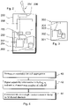
- Figure 5 illustrates an example of how to control the cell aggregation at the network side.
- capability information may be requested from it at 50.
- Information of a predefined maximum number of cells the communication device supports for cell aggregation on a single carrier resource can be received at 52 as a part of the requested capability information.
- Cell aggregation on the single carrier resource by the communication device can then be controlled based on the received information.
- the relevant network controller can assign communication channels and other resources at 54 up to the maximum number of cells and provide appropriate control for the communications on the single carrier resource at 56.
- cell aggregation capability categories of a communication device with reference to a communication device provided by a LTE enabled a user equipment (UE).
- UE user equipment
- categories only features that are needed to support single frequency cell aggregation are provided, with varying degree of sophistication.
- dual component carrier user equipments i.e. user equipments that can communicate on multiple frequencies, can get benefit from carrier aggregation and also from cell aggregation.
- single frequency carrier user equipments are not provided with all of the required essential features of the carrier aggregation capability set, as defined e.g. by LTE release 10.
- single frequency cell aggregation does not even require all of the UE capabilities that are defined for multi-frequency carrier aggregation (CA) in LTE Release 10 and that only a sub-set of the carrier aggregation capabilities would be required in support of cell aggregation. Such devices are nevertheless prevented from using cell aggregation due to the lacking features.
- CA multi-frequency carrier aggregation
- reduced user equipment (UE) capability sets are defined for a user equipment for use in cell aggregation.
- UE CA features defined in LTE Release 10 are arranged in subgroups such that one or multiple new UE capability classes or sets can be provided for single frequency cell aggregation.
- CA carrier aggregation
- the categorization of user equipment capabilities based on the existing carrier aggregation framework enables production of several different cell aggregation user equipment capability groups and user equipments with different level of complexity and cost.
- cell aggregation may be supported at an optimised complexity and cost, depending on the needs of users.
- Use of the existing features as a starting point may also provide advantage in that a minimal amount of standardization is required since existing carrier aggregation features may be reused.
- Simultaneous or non-simultaneous downlink (DL) reception and/or uplink (UL) transmissions can be supported depending on the capability class.
- the non-simultaneous communications can be separated by means of time division multiplexing (TDM).
- TDM time division multiplexing
- a parameter for cell aggregation capability can be signalled from the user equipment in user equipment (UE) capability signalling for indication of the number of downlink (DL) same frequency cells which the user equipment can aggregate.
- UE user equipment
- DL downlink
- a base station can ask from the UE for its capability information and the UE can signal the capability information with an indication of its cell aggregation capabilities back to the base station.
- Signalling of the cell aggregation capability information can be explicit or implicit.
- a parameter indicating the maximum number of supported cells is denoted in the following as M.
- the arrangement can be such that it only uses cell aggregation when radio conditions are such that use of cell aggregation is beneficial. For example, if the user equipment can only detect one cell there is no need for it even to try to connect to more cells.
- the parameter M can be defined by the vendor of the user equipment, for example based on a standardised framework of user equipment categories.
- High M value can mean relatively high requirements from the user equipment implementation. For example, baseband processing, signalling support, measurement capability, and so forth are required. This also means increased complexity and higher cost of user equipment chipset, and thus would most likely be used for high-end user equipments.
- a lower M would in this scenario mean less complex and thus easier implementation, thus resulting a lower cost user equipment.
- cell aggregation capability sets can be provided based on the features of a multi-frequency capability set, such as the LTE Release 10 capability set discussed above.
- Non-limiting examples of possible capability sets are referred below as cell aggregation capability sets 1 to 5.
- Cell aggregation Capability set 1 provides for downlink (DL) cross cell scheduling. Based on this set an user equipment is capable of supporting:
- Cell aggregation Capability set 2 for DL cell aggregation Based on this set an user equipment (UE) is capable of:
- Cell aggregation Capability set 3 for advanced DL cell aggregation. This set is a combination of capability sets 1 and 2 above. Based on this set user equipment capabilities are:
- Cell aggregation Capability set 4 for UL cell aggregation This set requires cell aggregation capability of set 1, 2 or 3.
- User equipment configured in accordance with this set is capable of:
- a fifth cell aggregation capability set can be provided by adding UL grants with cell indicator to capability set 4.
- the above capability sets highlight the features that differentiate between the different capability categories 1 to 5.
- the lists are not exhaustive and other features of a control channel may be provided in practise.
- the other features can also be based on the full carrier aggregation (CA) capability set.
- CA full carrier aggregation
- feedback mechanism such as Ack/Nak on Physical Uplink Shared Channel (PUSCH) / Physical Uplink Control Channel (PUCCH) and/or Channel Quality Indicator/ Precoding Matrix Index/ Rank Indicator (CQI/PMI/RI) periodical / aperiodical feedback may be added.
- PUSCH Physical Uplink Shared Channel
- PUCCH Physical Uplink Control Channel
- CQI/PMI/RI Channel Quality Indicator/ Precoding Matrix Index/ Rank Indicator
- a more detailed example of the further features is described below where a set of possible cell aggregation capability requirements is given in relation to the above aggregation capability set 1:
- cell aggregation Dario frequency may be needed for a multiple UL PUSCH.
- PDSCH decoding may be needed for multiple composite carriers.
- more PDCCH search space may be needed. Optimisation of these requirements by means of the user categorization can be used to manage the complexity and implementation cost of a communication device such as a mobile user equipment.
- single frequency cell aggregation can be used to provide flexibility and benefit to overall system performance.
- An existing carrier aggregation capability set can be modified to allow coordinated multi-point transmission (CoMP) on a single frequency.
- component carriers (CC) can be configured with the same frequency to allow single frequency cell aggregation as a CoMP technique.
- the carrier aggregation is allowed to have cross-carrier scheduling.
- Cross cell scheduling can be used for example to transmit a primary cell downlink from a macro cell and a secondary cell uplink in a pico cell.
- a carrier comprising may be provided by a communication device such as a mobile user equipment.
- a communication device such as a mobile user equipment.
- this may be the case in application where no fixed equipment provided but a communication system is provided by means of a plurality of user equipment, for example in adhoc networks.
- the aforementioned examples can be adopted for example to orthogonal frequency division multiple access (OFDMA) frequency division duplex (FDD) based mobile communication system other than LTE, although the independent claims recite an LTE communication system and an LTE communication device.
- OFDMA orthogonal frequency division multiple access
- FDD frequency division duplex
- the required data processing apparatus and functions of a base station apparatus, a communication device and any other appropriate apparatus may be provided by means of one or more data processors.
- the described functions at each end may be provided by separate processors or by an integrated processor.
- the data processors may be of any type suitable to the local technical environment, and may include one or more of general purpose computers, special purpose computers, microprocessors, digital signal processors (DSPs), application specific integrated circuits (ASIC), gate level circuits and processors based on multi core processor architecture, as non limiting examples.
- the data processing may be distributed across several data processing modules.
- a data processor may be provided by means of, for example, at least one chip. Appropriate memory capacity can also be provided in the relevant devices.
- the memory or memories may be of any type suitable to the local technical environment and may be implemented using any suitable data storage technology, such as semiconductor based memory devices, magnetic memory devices and systems, optical memory devices and systems, fixed memory and removable memory.
- the various examples may be implemented in hardware or special purpose circuits, software, logic or any combination thereof.
- Some aspects of the invention may be implemented in hardware, while other aspects may be implemented in firmware or software which may be executed by a controller, microprocessor or other computing device, although the invention is not limited thereto. While various aspects of the invention may be illustrated and described as block diagrams, flow charts, or using some other pictorial representation, it is well understood that these blocks, apparatus, systems, techniques or methods described herein may be implemented in, as non-limiting examples, hardware, software, firmware, special purpose circuits or logic, general purpose hardware or controller or other computing devices, or some combination thereof.
- the software may be stored on such physical media as memory chips, or memory blocks implemented within the processor, magnetic media such as hard disk or floppy disks, and optical media such as for example DVD and the data variants thereof, CD.
Description
- The application relates to resource aggregation in wireless communications and more particularly to single carrier resource aggregation in a communication system.
- A communication system can be seen as a facility that enables communication sessions between two or more nodes such as fixed or mobile communication devices, access nodes such as base stations, servers and so on. A communication system and compatible communicating entities typically operate in accordance with a given standard or specification which sets out what the various entities associated with the system are permitted to do and how that should be achieved. For example, the standards, specifications and related protocols can define the manner how communication devices shall communicate with the access nodes, how various aspects of the communications shall be implemented and how the devices shall be configured.
- A communication can be carried on wired or wireless carriers. Examples of wireless systems include public land mobile networks (PLMN) such as cellular networks, satellite based communication systems and different wireless local networks, for example wireless local area networks (WLAN). Wireless systems can be divided into coverage areas referred to as cells, such systems being often referred to as cellular systems. An example of cellular communication systems is an architecture that is being standardized by the 3rd Generation Partnership Project (3GPP). This system is often referred to as the long-term evolution (LTE) of the Universal Mobile Telecommunications System (UMTS) radio-access technology. A further development of the LTE is often referred to as LTE-Advanced. The various development stages of the 3GPP LTE specifications are referred to as releases.
- Radio services areas are typically referred to as cells. A cell can be provided by a base station, there being various different types of base stations. Different types of cells can provide different features. For example, cells can have different shapes, sizes and other characteristics.
- A user can access the communication system by means of an appropriate communication device. A communication device of a user is often referred to as user equipment (UE) or terminal. A communication device is provided with an appropriate signal receiving and transmitting arrangement for enabling communications with other parties. Typically a communication device is used for enabling receiving and transmission of communications such as speech and data. In wireless systems a communication device provides a transceiver station that can communicate with another communication device such as e.g. a base station of an access network and/or another user equipment. The communication device may access a carrier provided by a base station, and transmit and/or receive communications on the carrier.
- The 3GPP document "Control plane aspects of carrier aggregation", Ericsson, R2-092958, 28 April 2009, discloses aspects of carrier aggregation for LTE. Qualcomm Incorporated "Summary of System Performance Evaluation of SF-DC aggregation Schemes Assuming Realistic RLC and Flow Control relates to the system performance of various Multi-Point HSPDA schemes. 3GPP; Technical Specification Group Radio Access Network; HSDPA Multipoint Transmission (Release 11) relates to HSDPA Multipoint Transmission. Carrier aggregation (CA) can be used to increase performance. In carrier aggregation a plurality of component carriers on different frequencies are aggregated to increase bandwidth. In accordance with LTE Release 10 user equipment carrier aggregation (UE CA) capability integrates all carrier aggregation (CA) features in a capability set. In LTE release 10 UE CA capability has been comprehensively defined and includes features such as those related to UE radio frequency (RF) properties, decoding/encoding, hybrid automatic repeat request (HARQ) signalling support, blind decoding, the secondary serving cell (SCC) management, dual-Component Carrier capability, capability to monitor physical downlink control channel (PDCCH) on multiple cells, and so on. In other words, if a user equipment supports carrier aggregation (CA), it shall support all CA related features. Such a user equipment is necessarily a dual component carrier capable user equipment operable on multiple frequency resources. However, a user equipment that is capable only for communications on a single frequency carrier at a time cannot be configured to support the required dual component carrier aggregation related features and thus cannot provide any aggregation. On the other hand, single frequency communication devices may be desired in certain occasions, for example due to the lesser complexity and cost thereof.
- The present invention is defined by the appended independent claims. Certain more specific aspects are defined by the dependent claims.
- Examples will now be described in further detail, by way of example only, with reference to the following examples and accompanying drawings, in which:
-
Figure 1 shows a schematic diagram of a network according to some examples; -
Figure 2 shows a schematic diagram of a mobile communication device according to some examples; -
Figure 3 shows a schematic diagram of a control apparatus according to some examples; and -
Figures 4 and5 show schematically flowcharts according to certain examples. - In the following certain examples are explained with reference to a wireless or mobile communication system serving mobile communication devices. Before explaining in detail the exemplifying embodiments, certain general principles of a wireless communication system, access systems thereof, and mobile communication devices are briefly explained with reference to
Figures 1 to 3 to assist in understanding the technology underlying the described examples. - A non-limiting example of the recent developments in communication system architectures is the long-term evolution (LTE) of the Universal Mobile Telecommunications System (UMTS) that is being standardized by the 3rd Generation Partnership Project (3GPP). As explained above, further development of the LTE is referred to as LTE-Advanced. The LTE employs a mobile architecture known as the Evolved Universal Terrestrial Radio Access Network (E-UTRAN). Base stations of such systems are known as evolved or enhanced Node Bs (eNBs) and may provide E-UTRAN features such as user plane Radio Link Control/Medium Access Control/Physical layer protocol (RLC/MAC/PHY) and control plane Radio Resource Control (RRC) protocol terminations towards the communication devices. Other examples of radio access system include those provided by base stations of systems that are based on technologies such as wireless local area network (WLAN) and/or WiMax (Worldwide Interoperability for Microwave Access).
- A
communication device figure 1 different neighbouring and/or overlapping access systems orradio service areas base stations Figure 1 . It shall be understood that the sizes and shapes of the cells or other radio service areas may vary considerably from the similarly sized omni-directional shapes ofFigure 1 . - A base station site can provide one or more cells or sectors, each sector providing a cell or a subarea of a cell. A radio link within a cell can be identified by a single logical identification. Each communication device and base station may have one or more radio channels open at the same time and may send signals to and/or receive signals from more than one source
- Base stations are typically controlled by at least one appropriate controller apparatus so as to enable operation thereof and management of mobile communication devices in communication with the base stations.
Figure 1 showscontrol apparatus - Different types of possible cells include those known as macro cells, pico cells and femto cells. For example, in LTE-Advanced the transmission/reception points or base stations can comprise wide area network nodes such as a macro eNode B (eNB) which may, for example, provide coverage for an entire cell or similar radio service area. Base station can also be provided by small or local radio service area network nodes, for example Home eNBs (HeNB), pico eNodeBs (pico-eNB), or femto nodes. Some applications utilise radio remote heads (RRH) that are connected to for example an eNB. Cell areas typically overlap, and thus a communication device in an area can listen to more than one base station. Smaller radio service areas can be located entirely or at least partially within a larger radio service area. A communication may thus communicate with more than one cell. In some embodiments LTE-Advanced network nodes can comprise a combination of wide area network nodes and small area network nodes deployed using the same frequency carriers (e.g. co-channel deployment).
- In particular,
Figure 1 depicts afirst cell 100. In this example thefirst cell 100 is provided by a widearea base station 106, which can be a macro-eNB. The macro-eNB 106 transmits and receives data over the entire coverage of thecell 100. Asecond cell 110 in this example is a pico-cell. Athird cell 117 is provided by a suitable smallarea network node 118 such as Home eNBs (HeNB) (femto cell) or another pico eNodeBs (pico-eNB). HeNBs may be configured to support local offload and may support any user equipment (UE) or UEs belonging to a closed subscriber group (CSG) or an open subscriber group (OSG) and transmit and receive data over the coverage area of thethird cell 117. Afourth cell 119 is provided by a remote radio head (RRH) 120 connected to the base station apparatus ofcell 100. - One technique of communicating over a wireless interface relies on combining the results of detecting a transmission from a communications device at a plurality of cells or detecting a transmission based on signals transmitted from a plurality of cells. This is commonly known as coordinated multipoint transmission (CoMP). CoMP can be provided for example in heterogeneous network scenarios where there is a centralised processing unit, for example where there is a single controlling macro eNB.
- In
Figure 1 stations wider communications network 113 viagateway 112. A further gateway function may be provided to connect to another network. Thesmaller stations network 113, for example by a separate gateway function and/or via the macro level cells. In the example,station 118 is connected via agateway 111 whilststation 120 connects via thecontroller apparatus 108. Base station may communicate via each other via fixed line connection and/or air interface, for example over an X2 interface. - As shown, each of the
communication devices cell base station 106 and its associatedcontroller 109 which is further coupled to the pico cellbase station controller 109 and to thefemto cell gateway 111. The macrocell base station 106 is configured to communicate to communication devices operating within the range of the macro cell in such a way that the downlink is able to transmit control and signal information from the macro cell base station antenna to the communication devices. Similarly,communication devices cell base station 107 and also in some embodiments transmit at least control information via a control channel to the macrocell base station 106.Communication device 103 may also communicate with at least one ofcells - A possible mobile communication device for transmitting to and receiving from a plurality of base stations will now be described in more detail with reference to
Figure 2 showing a schematic, partially sectioned view of acommunication device 200. Such a communication device is often referred to as user equipment (UE) or terminal. An appropriate mobile communication device may be provided by any device capable of sending radio signals to and/or receiving radio signals from multiple cells. Non-limiting examples include a mobile station (MS) such as a mobile phone or what is known as a 'smart phone', a portable computer provided with a wireless interface card or other wireless interface facility, personal data assistant (PDA) provided with wireless communication capabilities, or any combinations of these or the like. A mobile communication device may provide, for example, communication of data for carrying communications such as voice, electronic mail (email), text message, multimedia and so on. Users may thus be offered and provided numerous services via their communication devices. Non-limiting examples of these services include two-way or multi-way calls, data communication or multimedia services or simply an access to a data communications network system, such as the Internet. User may also be provided broadcast or multicast data. Non-limiting examples of the content include downloads, television and radio programs, videos, advertisements, various alerts and other information. - The mobile device may receive signals over an
air interface 207 via appropriate apparatus for receiving and may transmit signals via appropriate apparatus for transmitting radio signals. InFigure 2 transceiver apparatus is designated schematically byblock 206. Thetransceiver apparatus 206 may be provided for example by means of a radio part and associated antenna arrangement. The antenna arrangement may be arranged internally or externally to the mobile device. - A mobile communication device is also provided with at least one
data processing entity 201, at least onememory 202 and otherpossible components 203 for use in software and hardware aided execution of tasks it is designed to perform, including control of access to and communications with access systems and other communication devices. The data processing, storage and other relevant control apparatus can be provided on an appropriate circuit board and/or in chipsets. This feature is denoted byreference 204. - The user may control the operation of the mobile device by means of a suitable user interface such as
key pad 205, voice commands, touch sensitive screen or pad, combinations thereof or the like. Adisplay 208, a speaker and a microphone can be also provided. Furthermore, a mobile communication device may comprise appropriate connectors (either wired or wireless) to other devices and/or for connecting external accessories, for example hands-free equipment, thereto. -
Figure 3 shows an example of a control apparatus for a communication system, for example to be coupled to and/or for controlling a station of an access system. In some embodiments base stations comprise a separate control apparatus. In other embodiments the control apparatus can be another network element. Thecontrol apparatus 300 can be arranged to provide control on communications in the service area of the system. Thecontrol apparatus 300 can be configured to provide control functions in association with cell aggregation on a single carrier resource by means of the data processing facility in accordance with certain embodiments described below. For this purpose the control apparatus comprises at least onememory 301, at least onedata processing unit output interface 304. Via the interface the control apparatus can be coupled to a receiver and a transmitter of the base station. The control apparatus can be configured to execute an appropriate software code to provide the control functions. It shall be appreciated that similar component can be provided in a control apparatus provided elsewhere in the system for controlling reception of sufficient information for decoding of received information blocks. - A wireless communication device, such as a mobile or base station, can be provided with a Multiple Input / Multiple Output (MIMO) antenna system. MIMO arrangements as such are known. MIMO systems use multiple antennas at the transmitter and receiver along with advanced digital signal processing to improve link quality and capacity. The
transceiver apparatus 206 ofFigure 2 can provide a plurality of antenna ports. More data can be received and/or sent where there are more antennae elements. - The following describes certain examples where cell aggregation is provided for communication by a communication device. Cell aggregation can be understood as an intra-frequency inter-site combination, a difference to carrier aggregation being that carrier aggregation is provided over multiple frequencies whereas cell aggregation can be provided on a single carrier resource, such as on a single frequency band. Therefore cell aggregation requires different capability from the communication device to that of carrier aggregation. For example, a cell aggregation capable radio only needs to support one frequency.
-
Figure 4 shows an example for operation at a communication device that is capable for cell aggregation. Atstep 40 the communication device may determine if cell aggregation would provide any benefit, or if it is even possible. At 42 the communication device can then signal information regarding a predefined maximum number of cells that can be aggregated by a communication device on a single carrier resource. Based on this information the network can control the communication accordingly and assign appropriate resources, where after support can be provided at 44 for cell aggregation for communications by the communication device on the single carrier resource with a multiple of cells up to said maximum number of cells. -
Figure 5 illustrates an example of how to control the cell aggregation at the network side. When a new communication device enters a cell, capability information may be requested from it at 50. Information of a predefined maximum number of cells the communication device supports for cell aggregation on a single carrier resource can be received at 52 as a part of the requested capability information. Cell aggregation on the single carrier resource by the communication device can then be controlled based on the received information. For example, the relevant network controller can assign communication channels and other resources at 54 up to the maximum number of cells and provide appropriate control for the communications on the single carrier resource at 56. - The following more detailed examples describe cell aggregation capability categories of a communication device with reference to a communication device provided by a LTE enabled a user equipment (UE). In the described user equipment categories only features that are needed to support single frequency cell aggregation are provided, with varying degree of sophistication. As discussed above, dual component carrier user equipments, i.e. user equipments that can communicate on multiple frequencies, can get benefit from carrier aggregation and also from cell aggregation. However, single frequency carrier user equipments are not provided with all of the required essential features of the carrier aggregation capability set, as defined e.g. by LTE release 10. The inventors have found that single frequency cell aggregation does not even require all of the UE capabilities that are defined for multi-frequency carrier aggregation (CA) in LTE Release 10 and that only a sub-set of the carrier aggregation capabilities would be required in support of cell aggregation. Such devices are nevertheless prevented from using cell aggregation due to the lacking features.
- In accordance with certain examples reduced user equipment (UE) capability sets are defined for a user equipment for use in cell aggregation. In accordance with an example UE CA features defined in LTE Release 10 are arranged in subgroups such that one or multiple new UE capability classes or sets can be provided for single frequency cell aggregation. In each capability class only a subset of LTE Release 10 carrier aggregation (CA) features is supported. Thus a plurality of different user equipment categories or types can be provided, each of the types and related behaviours supporting multiple serving cells on a single carrier resource. For example, monitoring of temporary identifiers assigned for the user equipment by the access system can be handled differently, depending on the capability set configuration. Also, granting of physical shared channels and communications on physical shared channels (e.g. PDSCH, PUSCH) can be handled differently depending on the configured capabilities. Further examples where different configurations may be provided depending on the capability set relate to downlink assignments and power control.
- The categorization of user equipment capabilities based on the existing carrier aggregation framework enables production of several different cell aggregation user equipment capability groups and user equipments with different level of complexity and cost. Thus cell aggregation may be supported at an optimised complexity and cost, depending on the needs of users. Use of the existing features as a starting point may also provide advantage in that a minimal amount of standardization is required since existing carrier aggregation features may be reused.
- Simultaneous or non-simultaneous downlink (DL) reception and/or uplink (UL) transmissions can be supported depending on the capability class. The non-simultaneous communications can be separated by means of time division multiplexing (TDM).
- In accordance with an example a parameter for cell aggregation capability can be signalled from the user equipment in user equipment (UE) capability signalling for indication of the number of downlink (DL) same frequency cells which the user equipment can aggregate. For example, a base station can ask from the UE for its capability information and the UE can signal the capability information with an indication of its cell aggregation capabilities back to the base station. Signalling of the cell aggregation capability information can be explicit or implicit. For simplicity, a parameter indicating the maximum number of supported cells is denoted in the following as M.
- It is noted that even if the user equipment supports cell aggregation feature up to M cells, the arrangement can be such that it only uses cell aggregation when radio conditions are such that use of cell aggregation is beneficial. For example, if the user equipment can only detect one cell there is no need for it even to try to connect to more cells.
- The parameter M can be defined by the vendor of the user equipment, for example based on a standardised framework of user equipment categories. High M value can mean relatively high requirements from the user equipment implementation. For example, baseband processing, signalling support, measurement capability, and so forth are required. This also means increased complexity and higher cost of user equipment chipset, and thus would most likely be used for high-end user equipments. A lower M would in this scenario mean less complex and thus easier implementation, thus resulting a lower cost user equipment.
- Various possible user equipment cell aggregation capability categories can be provided based on the features of a multi-frequency capability set, such as the LTE Release 10 capability set discussed above. Non-limiting examples of possible capability sets are referred below as cell aggregation capability sets 1 to 5.
- Cell aggregation Capability set 1 provides for downlink (DL) cross cell scheduling. Based on this set an user equipment is capable of supporting:
- 1. A physical downlink control channel (PDCCH) monitoring for a Cell Radio Network Temporary identity (C-RNTI) on a user equipment specific search space for one Serving Cell. Up to M PDCCHs can be provided in one user equipment specific search space per user equipment. The channels are provided non-simultaneously.
- 2. Physical Downlink Shared Channel (PDSCH) reception on up to M Serving Cells on same frequency. The reception is non-simultaneous.
- 3. DL assignments with cell indicator (Carrier or Cell Indicator Field) CIF for CA cross scheduling can be reused, and thus no new LTE Downlink Control Information (DCI) formats need to be defined.
- Cell aggregation Capability set 2 for DL cell aggregation. Based on this set an user equipment (UE) is capable of:
- 1. PDCCH monitoring for C-RNTI on user equipment specific search space on M Serving Cells.
- 2. PDSCH reception on up to M Serving Cells on same frequency.
- 3. DL assignments without cell indicator (CIF bits in accordance with LTE Release10 Downlink Control Information; DCI)
- Cell aggregation Capability set 3 for advanced DL cell aggregation. This set is a combination of capability sets 1 and 2 above. Based on this set user equipment capabilities are:
- 1. PDCCH monitoring for C-RNTI on user equipment specific search space on M Serving Cells.
- 2. PDCCH monitoring for C-RNTI on multiple UE specific search spaces on one serving Cell.
- 3. PDSCH from any cell can only be granted by PDCCH in one cell.
- 4. PDSCH reception, on up to M Serving Cells on same frequency.
- 5. DL assignments with cell indicator
- Cell aggregation Capability set 4 for UL cell aggregation. This set requires cell aggregation capability of set 1, 2 or 3. User equipment configured in accordance with this set is capable of:
- 1. PUSCH transmission on up to M Serving Cells on same frequency. The transmissions are not simultaneous.
- 2. Physical Hybrid ARQ Indicator Channel (PHICH) reception for PUSCH transmissions on up to M serving cells (SCells).
- 3. Periodic Sounding Reference Symbols (SRS) transmission on M Serving Cells, as per RRC configuration on same frequency, not simultaneous.
- 4. Power control on a per Serving Cell basis
- According to a possibility a fifth cell aggregation capability set can be provided by adding UL grants with cell indicator to capability set 4.
- The above capability sets highlight the features that differentiate between the different capability categories 1 to 5. Naturally, the lists are not exhaustive and other features of a control channel may be provided in practise. The other features can also be based on the full carrier aggregation (CA) capability set. For example, feedback mechanism such as Ack/Nak on Physical Uplink Shared Channel (PUSCH) / Physical Uplink Control Channel (PUCCH) and/or Channel Quality Indicator/ Precoding Matrix Index/ Rank Indicator (CQI/PMI/RI) periodical / aperiodical feedback may be added. A more detailed example of the further features is described below where a set of possible cell aggregation capability requirements is given in relation to the above aggregation capability set 1:
- 1) PDCCH monitoring for C-RNTI on UE specific search space for one Serving Cell (S-Cell). Up to M PDCCH in one UE specific search space per UE can be monitored. The monitoring is provided non-simultaneously.
- 2) PDSCH reception, on up to M Serving Cells on same frequency, non-simultaneously.
- 3) DL assignments with cell indicator (CIF for CA cross scheduling can be reused, and thus no new DCI format needs to be defined)
- 4) PDSCH starting position determination by decoding of Physical Control Format Indicator Channel (PCFICH), on N Serving Cells.
- 5) Error correction Ack/Nack feedback, for up to N Serving Cells altogether on:
- PUSCH
- PUCCH format 1b with channel selection
- -> for FDD and TDD using mode a) (N/A when there are more than 4 Ack/Nack bits)
- -> for TDD using mode b) (time and spatial domain Ack/Nack bundling)
- only if UE supports more than 4 Ack/Nack bits, PUCCH format 3
- 6) CQI/PMI/RI
- aperiodic reporting, for any of the N Serving Cells (SCell), as per channel quality indicator (CQI) request in UL grants
- periodic reporting, for N Serving Cells, as per radio resource control (RRC) configuration
- 7) one DL-SCH (Downlink Shared Channel) and one hybrid automatic repeat request (HARQ) entity, for each of the N Serving Cells
- 8) HARQ entity initialization/removal at SCell addition/release
- 9) Procedures related to SCell activation/deactivation
- 10) SCell addition, modification and release
- with the (non-handover) reconfiguration procedure
- with the handover procedure
- 11) SCell release at RRC connection re-establishment
- 12) SCell measurement result inclusion in Measurement Reports
- 13) Best non-serving cell reporting in measurement reports
- 14) 'NeedForGaps' indicaton for each measurement band for each operating band / band combination
- 15) Periodical measurement on SCCs
- 16) Measurement reporting trigger Event A1, for SCell
- 17) Measurement reporting trigger Event A2, for Scell
- 18) Autonomous measurement identity removal
- 19) Measurement reporting trigger Event A6
- 20) SCell addition within the handover to EUTRA procedure (relevant if UE supports handover to EUTRA)
- In cell aggregation Dario frequency may be needed for a multiple UL PUSCH. Furthermore, PDSCH decoding may be needed for multiple composite carriers. Also, more PDCCH search space may be needed. Optimisation of these requirements by means of the user categorization can be used to manage the complexity and implementation cost of a communication device such as a mobile user equipment.
- In the examples single frequency cell aggregation can be used to provide flexibility and benefit to overall system performance. An existing carrier aggregation capability set can be modified to allow coordinated multi-point transmission (CoMP) on a single frequency. Technically, component carriers (CC) can be configured with the same frequency to allow single frequency cell aggregation as a CoMP technique. The carrier aggregation is allowed to have cross-carrier scheduling. Cross cell scheduling can be used for example to transmit a primary cell downlink from a macro cell and a secondary cell uplink in a pico cell.
- It is noted that whilst examples have been described in relation to LTE-Advanced, similar principles can be applied to any other communication system or indeed to further developments with LTE. Also, instead of carriers provided by a base station a carrier comprising may be provided by a communication device such as a mobile user equipment. For example, this may be the case in application where no fixed equipment provided but a communication system is provided by means of a plurality of user equipment, for example in adhoc networks. Therefore, although certain examples were described above by way of example with reference to certain exemplifying architectures for wireless networks, technologies and standards, embodiments may be applied to any other suitable forms of communication systems than those illustrated and described herein. In some other examples the aforementioned examples can be adopted for example to orthogonal frequency division multiple access (OFDMA) frequency division duplex (FDD) based mobile communication system other than LTE, although the independent claims recite an LTE communication system and an LTE communication device.
- The required data processing apparatus and functions of a base station apparatus, a communication device and any other appropriate apparatus may be provided by means of one or more data processors. The described functions at each end may be provided by separate processors or by an integrated processor. The data processors may be of any type suitable to the local technical environment, and may include one or more of general purpose computers, special purpose computers, microprocessors, digital signal processors (DSPs), application specific integrated circuits (ASIC), gate level circuits and processors based on multi core processor architecture, as non limiting examples. The data processing may be distributed across several data processing modules. A data processor may be provided by means of, for example, at least one chip. Appropriate memory capacity can also be provided in the relevant devices. The memory or memories may be of any type suitable to the local technical environment and may be implemented using any suitable data storage technology, such as semiconductor based memory devices, magnetic memory devices and systems, optical memory devices and systems, fixed memory and removable memory.
- In general, the various examples may be implemented in hardware or special purpose circuits, software, logic or any combination thereof. Some aspects of the invention may be implemented in hardware, while other aspects may be implemented in firmware or software which may be executed by a controller, microprocessor or other computing device, although the invention is not limited thereto. While various aspects of the invention may be illustrated and described as block diagrams, flow charts, or using some other pictorial representation, it is well understood that these blocks, apparatus, systems, techniques or methods described herein may be implemented in, as non-limiting examples, hardware, software, firmware, special purpose circuits or logic, general purpose hardware or controller or other computing devices, or some combination thereof. The software may be stored on such physical media as memory chips, or memory blocks implemented within the processor, magnetic media such as hard disk or floppy disks, and optical media such as for example DVD and the data variants thereof, CD.
- The foregoing description has provided by way of exemplary and non-limiting examples a full and informative description of the exemplary embodiment of this invention. However, various modifications and adaptations may become apparent to those skilled in the relevant arts in view of the foregoing description, when read in conjunction with the accompanying drawings and the appended claims. However, all such and similar modifications of the teachings of this invention will still fall within the scope of this invention as defined in the appended claims. Indeed there is a further example comprising a combination of one or more of any of the other examples previously discussed.
Claims (18)
- An apparatus for a long-term evolution, LTE, communication device (200), the apparatus comprising at least one processor (201), and at least one memory (202) including computer program code, wherein the at least one memory and the computer program code are configured, with the at least one processor, to:support cell aggregation for communications with a multiple of cells of an LTE communication system based on a predefined maximum number of cells on a single carrier resource that can be aggregated by the LTE communication device; andsignal (42) information of the predefined maximum number of cells the LTE communication device supports for cell aggregation on a single carrier resource to an apparatus for controlling cell aggregation.
- A apparatus for controlling cell aggregation, the apparatus comprising at least one processor, and at least one memory including computer program code, wherein the at least one memory and the computer program code are configured, with the at least one processor, toreceive from a long-term evolution, LTE, communication device information of a predefined maximum number of cells the LTE communication device supports for cell aggregation on a single carrier resource, andcontrol cell aggregation by the LTE communication device based on the information.
- An apparatus according to claim 1 or 2, wherein the apparatus is configured to handle signalling of an indication of the maximum number of cells from the communication device, the signalling being explicit or implicit.
- An apparatus according to claim 3, wherein the indication is signalled in capability information of the communication device.
- An apparatus according to any preceding claim, wherein the communication device is configured for simultaneous transmission to and/or reception from multiple cells on the single carrier resource or to separate transmission and/or reception on the single carrier resource based on time division multiplexing.
- An apparatus according to any preceding claim, wherein the single carrier resource comprises a single frequency carrier.
- An apparatus according to any preceding claim, wherein the predefined maximum number of cells defines the maximum number of physical shared channels and/or physical control channels that can be received or transmitted by the communication device.
- An apparatus according to any preceding claim, configured to cause monitoring of an identity at a time in a search space up to the predefined maximum number of cells or monitoring of a plurality of identities in a search space up to the predefined maximum number of cells.
- An apparatus according to any preceding claim, wherein signalling for controlling cell aggregation by the communication device is provided by a controller associated with a cell or by controller apparatus associated with a plurality of cells.
- An apparatus according to any preceding claim, configured to support the single frequency resource communication with multiple cells based on a set of capabilities selected from a set of capabilities for communications on a multi-frequency component carrier.
- An arrangement comprising a first communication device comprising an apparatus according to any preceding claim and at least one second communication device, wherein the first communication device and the at least one second communication device are configured to provide cell aggregation on a single frequency resource based on different subsets of capabilities selected from a set of capabilities for aggregated component carrier communication on multiple frequency resources.
- A device comprising a communication device comprising apparatus in accordance with claim 1 or any claim dependent on claim 1 or a network element comprising an apparatus in accordance with claim 2 or any claim dependent on claim 2.
- A method for cell aggregation, comprising:supporting cell aggregation for communications with a multiple of cells of an LTE communication system based on a predefined maximum number of cells on a single carrier resource that can be aggregated by the LTE communication device; andsignalling (42) information of the predefined maximum number of cells the LTE communication device supports for cell aggregation on a single carrier resource to an apparatus for controlling cell aggregation.
- A method for controlling cell aggregation, comprising:receiving, from a long-term evolution, LTE, communication device, information of a predefined maximum number of cells the LTE communication device supports for cell aggregation on a single carrier resource, andcontrolling cell aggregation on the single carrier resource by the LTE communication device based on the information.
- A method according to claim 13 or 14, comprising communicating an indication of the maximum number of cells from the communication device to a controller of at least one cell, wherein signalling of the information of the predefined maximum number of cells is explicit or implicit.
- A method according to any of claims 13 to 15, comprising simultaneous transmission to and/or reception from multiple cells on the single carrier resource by the communication device.
- A method according to any of claims 13 to 16, wherein the predefined maximum number of cells defines the maximum number of physical shared channels and/or physical control channels that can be received or transmitted by the communication device.
- A method according to any of claims 13 to 17, comprising monitoring for identities in a search space up to the predefined maximum number of cells.
Applications Claiming Priority (1)
| Application Number | Priority Date | Filing Date | Title |
|---|---|---|---|
| PCT/CN2011/076851 WO2013004006A1 (en) | 2011-07-05 | 2011-07-05 | Method and apparatus for resource aggregation in wireless communications |
Publications (3)
| Publication Number | Publication Date |
|---|---|
| EP2730137A1 EP2730137A1 (en) | 2014-05-14 |
| EP2730137A4 EP2730137A4 (en) | 2015-04-01 |
| EP2730137B1 true EP2730137B1 (en) | 2022-11-09 |
Family
ID=47436453
Family Applications (1)
| Application Number | Title | Priority Date | Filing Date |
|---|---|---|---|
| EP11869150.0A Active EP2730137B1 (en) | 2011-07-05 | 2011-07-05 | Method and apparatus for resource aggregation in wireless communications |
Country Status (4)
| Country | Link |
|---|---|
| US (2) | US9853781B2 (en) |
| EP (1) | EP2730137B1 (en) |
| CN (1) | CN103597891B (en) |
| WO (1) | WO2013004006A1 (en) |
Families Citing this family (21)
| Publication number | Priority date | Publication date | Assignee | Title |
|---|---|---|---|---|
| US8797966B2 (en) | 2011-09-23 | 2014-08-05 | Ofinno Technologies, Llc | Channel state information transmission |
| CN103891162B (en) * | 2011-10-19 | 2017-10-03 | Lg电子株式会社 | The method of monitoring control channel and the wireless device using this method |
| US8879496B2 (en) | 2011-12-19 | 2014-11-04 | Ofinno Technologies, Llc | Beamforming codeword exchange between base stations |
| JP5943075B2 (en) * | 2012-06-20 | 2016-06-29 | 富士通株式会社 | Wireless communication system, wireless station, base station, and communication method |
| RU2015116905A (en) * | 2012-10-05 | 2016-11-27 | Интердиджитал Пэйтент Холдингз, Инк. | METHOD AND DEVICE FOR IMPROVING COATING OF MACHINE TYPE COMMUNICATION DEVICES (MTS) |
| JP6289818B2 (en) * | 2013-05-09 | 2018-03-07 | 株式会社Nttドコモ | User terminal and wireless communication method |
| CN110113792B (en) | 2013-08-05 | 2021-07-09 | 富士通互联科技有限公司 | Source main base station, target main base station, and target secondary base station |
| US9986590B2 (en) * | 2013-09-17 | 2018-05-29 | Lg Electronics Inc. | Method for concurrently accessing plurality of cells and user equipment |
| US20150256297A1 (en) * | 2014-03-06 | 2015-09-10 | Qualcomm Incorporated | Discarding hybrid automatic repeat request (harq) processes |
| US9876623B2 (en) | 2014-12-22 | 2018-01-23 | Samsung Electronics Co., Ltd. | Transmission of uplink control information in carrier aggregation with a large number of cells |
| JP2018050089A (en) * | 2015-01-29 | 2018-03-29 | シャープ株式会社 | Terminal device, base station device, integrated circuit and communication method |
| US20180020467A1 (en) * | 2015-02-03 | 2018-01-18 | Telefonaktiebolaget Lm Ericsson (Publ) | Scheduling voice-over-ip users in wireless systems using carrier aggregation |
| EP3089097A1 (en) * | 2015-04-28 | 2016-11-02 | Omikron Data Quality GmbH | Method for generating priority data for products |
| CN110719588B (en) * | 2015-05-15 | 2021-02-12 | 华为技术有限公司 | Communication device and method |
| JP6576015B2 (en) * | 2016-05-12 | 2019-09-18 | ノキア テクノロジーズ オーユー | SRS switching capability reported by UE |
| US10149182B2 (en) * | 2016-09-07 | 2018-12-04 | Apple Inc. | Device, system, and method for advertising device capability |
| US10271333B2 (en) | 2016-12-15 | 2019-04-23 | At&T Intellectual Property I, L.P. | Service aware carrier aggregation |
| CN110999109B (en) * | 2017-05-23 | 2021-10-22 | 华为技术有限公司 | Channel state information related feedback reporting and channel state information acquisition |
| US10645608B2 (en) * | 2017-10-24 | 2020-05-05 | At&T Intellectual Property I, L.P. | Systems and methods for on demand intelligent analytics dynamic access network slice switching and carrier aggregation |
| CN110740514B (en) * | 2018-07-20 | 2021-11-23 | 维沃移动通信有限公司 | Monitoring method and terminal equipment |
| CN117460007A (en) * | 2020-08-24 | 2024-01-26 | 华为技术有限公司 | Cell state switching method and device |
Family Cites Families (74)
| Publication number | Priority date | Publication date | Assignee | Title |
|---|---|---|---|---|
| GB2398455B (en) * | 2003-02-11 | 2007-09-26 | Ipwireless Inc | Method, base station and mobile station for TDD operation in a communication system |
| US20050090251A1 (en) * | 2003-10-07 | 2005-04-28 | Ravi Kuchibhotla | Apparatus and method for shared network |
| US7606213B2 (en) * | 2004-08-12 | 2009-10-20 | Qualcomm Incorporated | Wireless MAC layer throughput improvements |
| WO2007019807A1 (en) * | 2005-08-19 | 2007-02-22 | Zte Corporation | Method for implement hsdpa for td-scdma |
| US8897234B2 (en) * | 2005-09-07 | 2014-11-25 | Huawei Technologies Co., Ltd. | Method and apparatus for controlling carrier frequency in multi-carrier/cell system |
| US8839362B2 (en) * | 2006-07-31 | 2014-09-16 | Motorola Mobility Llc | Method and apparatus for managing transmit power for device-to-device communication |
| JP4840043B2 (en) * | 2006-09-21 | 2011-12-21 | ソニー株式会社 | Wireless communication system and wireless communication apparatus |
| EP1928115A1 (en) * | 2006-11-30 | 2008-06-04 | Nokia Siemens Networks Gmbh & Co. Kg | Adaptive modulation and coding in a SC-FDMA system |
| US8345582B2 (en) * | 2008-02-19 | 2013-01-01 | Ntt Docomo, Inc. | Mobile communications system, base station apparatus, user apparatus and method |
| US8082353B2 (en) * | 2008-05-13 | 2011-12-20 | At&T Mobility Ii Llc | Reciprocal addition of attribute fields in access control lists and profiles for femto cell coverage management |
| DE102008029353A1 (en) * | 2008-06-20 | 2009-12-31 | Fraunhofer-Gesellschaft zur Förderung der angewandten Forschung e.V. | Apparatus for assigning and estimating transmission symbols |
| CN101616484B (en) * | 2008-06-24 | 2013-06-05 | 华为技术有限公司 | Method, system and device for resource allocation |
| EP2311285A1 (en) * | 2008-08-13 | 2011-04-20 | Telefonaktiebolaget L M Ericsson (PUBL) | Reporting of multiple if/rat layer restrictions |
| CN101656979A (en) * | 2008-08-19 | 2010-02-24 | 华为技术有限公司 | Method, device and system for managing resources in multi-carrier system |
| WO2010056078A2 (en) * | 2008-11-14 | 2010-05-20 | 엘지전자주식회사 | Method and apparatus for information transmission in wireless communication system |
| US8107890B2 (en) * | 2008-12-04 | 2012-01-31 | Broadcom Corporation | Multiple frequency band multiple standard device with reduced blocker |
| KR101559797B1 (en) * | 2008-12-04 | 2015-10-26 | 엘지전자 주식회사 | Method of control information in wireless communication system |
| WO2010068069A2 (en) * | 2008-12-11 | 2010-06-17 | 엘지전자 주식회사 | Method for control channel detection in a multicarrier system |
| WO2010088536A1 (en) | 2009-01-30 | 2010-08-05 | Interdigital Patent Holdings, Inc. | Method and apparatus for component carrier aggregation in wireless communications |
| TWI442794B (en) * | 2009-03-12 | 2014-06-21 | Interdigital Patent Holdings | Method and apparatus for performing component carrier-specific reconfiguration |
| US20100254329A1 (en) * | 2009-03-13 | 2010-10-07 | Interdigital Patent Holdings, Inc. | Uplink grant, downlink assignment and search space method and apparatus in carrier aggregation |
| KR101746537B1 (en) * | 2009-04-21 | 2017-06-13 | 엘지전자 주식회사 | Method for trasmitting control information in wireless communication system and apparatus therefor |
| US8938247B2 (en) * | 2009-04-23 | 2015-01-20 | Qualcomm Incorporated | Sounding reference signal for coordinated multi-point operation |
| CN101873648B (en) | 2009-04-27 | 2013-02-20 | 电信科学技术研究院 | Sending method, system and equipment of information in LTE (Long Term Evolution) system |
| US8620280B2 (en) * | 2009-04-27 | 2013-12-31 | Samsung Electronics Co., Ltd. | Downlink single-user multi-cell mimo systems for interference mitigation |
| US8644260B2 (en) * | 2009-05-01 | 2014-02-04 | Qualcomm Incorporated | Apparatus and method for increasing reliability of serving cell change |
| US20110158164A1 (en) * | 2009-05-22 | 2011-06-30 | Qualcomm Incorporated | Systems and methods for joint processing in a wireless communication |
| HUE047638T2 (en) * | 2009-06-15 | 2020-05-28 | Guangdong Oppo Mobile Telecommunications Corp Ltd | System and method for sharing a control channel for carrier aggregation |
| EA023976B1 (en) * | 2009-06-18 | 2016-08-31 | Шарп Кабусики Кайся | Mobile communication system, base station device, mobile station device, and mobile communication method |
| TW201101895A (en) * | 2009-06-24 | 2011-01-01 | Htc Corp | Method and related communication device for enhancing power control mechanism |
| US20110003555A1 (en) * | 2009-07-06 | 2011-01-06 | Yu-Hsuan Guo | Method and Apparatus for PDCCH Monitoring |
| KR101237666B1 (en) * | 2009-07-28 | 2013-02-26 | 엘지전자 주식회사 | Method and apparatus of transmitting reference signal for reducing inter-cell interference in multiple input multiple output communication system |
| JP4989692B2 (en) * | 2009-07-29 | 2012-08-01 | シャープ株式会社 | Mobile communication system, base station apparatus, mobile station apparatus, and communication method |
| KR101631477B1 (en) * | 2009-08-05 | 2016-06-17 | 삼성전자주식회사 | Communication system for adaptively using single-point trnasmission/reception and coordinated multi-point trnasmission/reception |
| CN104917600B (en) * | 2009-08-28 | 2018-05-11 | 华为技术有限公司 | Member carrier collocation method, equipment and system under carrier aggregation scene |
| EP2293605B1 (en) * | 2009-09-02 | 2016-11-09 | HTC Corporation | Method of handling multimedia broadcast and multicast service transmission and reception and related communication device |
| CN102026324B (en) * | 2009-09-18 | 2014-01-29 | 电信科学技术研究院 | Method, equipment and system for reconfiguring aggregated cell |
| US8688120B2 (en) * | 2009-09-21 | 2014-04-01 | Electronics And Telecommunications Research Institute | Method for handover in multi-carrier system |
| JP5515559B2 (en) * | 2009-09-25 | 2014-06-11 | ソニー株式会社 | Communication system, base station, and communication apparatus |
| CA2771150C (en) * | 2009-09-28 | 2017-02-14 | Samsung Electronics Co., Ltd. | Extending physical downlink control channels |
| WO2011039923A1 (en) * | 2009-10-02 | 2011-04-07 | パナソニック株式会社 | Terminal device and retransmission control method |
| US20110105105A1 (en) * | 2009-11-02 | 2011-05-05 | Sagfors Mats Fredrik | Methods and Arrangements in a Wireless Communication System |
| KR20110052418A (en) * | 2009-11-11 | 2011-05-18 | 삼성전자주식회사 | Apparatus and method for discontinuous reception in wireless communication system |
| EP2515595A4 (en) * | 2009-12-17 | 2017-01-25 | LG Electronics Inc. | Method and apparatus for transmitting channel status information efficiently in a multi-carrier wireless communication system |
| US8804586B2 (en) * | 2010-01-11 | 2014-08-12 | Blackberry Limited | Control channel interference management and extended PDCCH for heterogeneous network |
| KR101740221B1 (en) * | 2010-01-18 | 2017-05-29 | 주식회사 골드피크이노베이션즈 | Method and Apparatus for allocating Channel State Information-Reference Signal in wireless communication system |
| JP5538930B2 (en) * | 2010-02-04 | 2014-07-02 | シャープ株式会社 | Mobile station apparatus, base station apparatus, radio communication system, and radio communication method |
| US8305987B2 (en) * | 2010-02-12 | 2012-11-06 | Research In Motion Limited | Reference signal for a coordinated multi-point network implementation |
| KR101651682B1 (en) * | 2010-02-16 | 2016-08-26 | 삼성전자주식회사 | Data transmission/reception method and apparatus using carrier component in mobile telecommunication system using multi carrier |
| CN102196610B (en) * | 2010-03-10 | 2016-03-02 | 中兴通讯股份有限公司 | A kind of method and system identifying IUR interface transmission bearer ability |
| US9516686B2 (en) * | 2010-03-17 | 2016-12-06 | Qualcomm Incorporated | Method and apparatus for establishing and maintaining peer-to-peer (P2P) communication on unlicensed spectrum |
| KR101703864B1 (en) * | 2010-04-29 | 2017-02-22 | 엘지전자 주식회사 | A method and a base station for transmitting control information, and a method and a user equipment for receiving control information |
| JP4812887B1 (en) * | 2010-04-30 | 2011-11-09 | 株式会社エヌ・ティ・ティ・ドコモ | Mobile communication method and mobile station |
| US9008647B2 (en) * | 2010-05-03 | 2015-04-14 | Intel Mobile Communications GmbH | Mobile radio communication network device, mobile terminal, and method for transmission/reception of control information |
| US20120113910A1 (en) * | 2010-05-06 | 2012-05-10 | Yu-Chih Jen | Method of Handling a Physical Uplink Control Channel Transmission and Related Communication Device |
| CN102264033B (en) * | 2010-05-27 | 2015-06-03 | 中兴通讯股份有限公司 | Method and device for processing MBMS (Multimedia Broadcast Multicast Service) statistics message |
| WO2011161624A1 (en) * | 2010-06-21 | 2011-12-29 | Telefonaktiebolaget L M Ericsson (Publ) | System and method for allocating transmission resources |
| KR101090812B1 (en) * | 2010-06-30 | 2011-12-08 | 현대자동차주식회사 | Gear train of automatic transmission for vehicles |
| JP5574172B2 (en) * | 2010-07-14 | 2014-08-20 | 株式会社ジェイテクト | Control device |
| RU2567377C2 (en) * | 2010-08-16 | 2015-11-10 | Телефонактиеболагет Л М Эрикссон (Пабл) | Nodes and method for enhancing positioning |
| US8687727B2 (en) * | 2010-11-05 | 2014-04-01 | Intel Corporation | Coordinated multi-point transmission using interference feedback |
| EP2642674B1 (en) * | 2010-11-17 | 2020-04-08 | LG Electronics Inc. | Method and device for aperiodically reporting channel state information in wireless connection system |
| US9008675B2 (en) * | 2010-11-22 | 2015-04-14 | Lg Electronics Inc. | Method and device for measuring a downlink in a wireless communication system |
| WO2012070914A2 (en) * | 2010-11-25 | 2012-05-31 | 엘지전자 주식회사 | Method and apparatus for transmitting a control channel and a data channel in a wireless communication system |
| US9930677B2 (en) * | 2010-12-07 | 2018-03-27 | Sharp Kabushiki Kaisha | Prioritizing multiple channel state information (CSI) reporting with carrier aggregation |
| KR102585652B1 (en) * | 2011-01-07 | 2023-10-05 | 인터디지탈 패튼 홀딩스, 인크 | Communicating channel state information (csi) of multiple transmission points |
| TWI615043B (en) * | 2011-02-07 | 2018-02-11 | 內數位專利控股公司 | Method and apparatus for operating supplementary cells in licensed exempt spectrum |
| US11057924B2 (en) * | 2011-04-30 | 2021-07-06 | Nokia Solutions And Networks Oy | Method and apparatus for decoupling uplink and downlink cell selection |
| US8630253B2 (en) * | 2011-05-02 | 2014-01-14 | Futurewei Technologies, Inc. | System and method for mapping data symbols |
| US8792924B2 (en) * | 2011-05-06 | 2014-07-29 | Futurewei Technologies, Inc. | System and method for multi-cell access |
| US8750114B2 (en) * | 2011-05-10 | 2014-06-10 | Qualcomm Incorporated | Enhanced flow control |
| TWI577215B (en) * | 2011-05-17 | 2017-04-01 | 內數位專利控股公司 | Method and apparatus for power control of a divided subframe transmission |
| US9480051B2 (en) * | 2011-06-10 | 2016-10-25 | Nokia Technologies Oy | Carrier aggregation |
| WO2012174213A1 (en) * | 2011-06-14 | 2012-12-20 | Interdigital Patent Holdings, Inc. | Methods, systems and apparatus for defining and using phich resources for carrier aggregation |
-
2011
- 2011-07-05 US US14/130,778 patent/US9853781B2/en active Active
- 2011-07-05 WO PCT/CN2011/076851 patent/WO2013004006A1/en active Application Filing
- 2011-07-05 CN CN201180071162.9A patent/CN103597891B/en active Active
- 2011-07-05 EP EP11869150.0A patent/EP2730137B1/en active Active
-
2017
- 2017-12-01 US US15/828,495 patent/US10680768B2/en active Active
Non-Patent Citations (2)
| Title |
|---|
| QUALCOMM INCORPORATED: "On deploying DC-HSDPA UEs in Single Frequency Networks", 3GPP DRAFT; R1-104157_ON DEPLOYING DC-HSDPA UES IN SC NETWORKS, 3RD GENERATION PARTNERSHIP PROJECT (3GPP), MOBILE COMPETENCE CENTRE ; 650, ROUTE DES LUCIOLES ; F-06921 SOPHIA-ANTIPOLIS CEDEX ; FRANCE, vol. RAN WG1, no. Dresden, Germany; 20100702, 5 July 2010 (2010-07-05), XP050598525 * |
| QUALCOMM INCORPORATED: "TP on Impact to RAN Specifications due to HSDPA MP-Tx", 3GPP DRAFT; R1_111845_TP_IMPACT_RAN_SPECS_HSDPA_MP-TX, 3RD GENERATION PARTNERSHIP PROJECT (3GPP), MOBILE COMPETENCE CENTRE ; 650, ROUTE DES LUCIOLES ; F-06921 SOPHIA-ANTIPOLIS CEDEX ; FRANCE, vol. RAN WG1, no. Barcelona, Spain; 20110509, 16 May 2011 (2011-05-16), XP050491486 * |
Also Published As
| Publication number | Publication date |
|---|---|
| US20140169343A1 (en) | 2014-06-19 |
| EP2730137A1 (en) | 2014-05-14 |
| US20180091268A1 (en) | 2018-03-29 |
| US10680768B2 (en) | 2020-06-09 |
| WO2013004006A1 (en) | 2013-01-10 |
| CN103597891B (en) | 2018-05-25 |
| EP2730137A4 (en) | 2015-04-01 |
| US9853781B2 (en) | 2017-12-26 |
| CN103597891A (en) | 2014-02-19 |
Similar Documents
| Publication | Publication Date | Title |
|---|---|---|
| US10680768B2 (en) | Method and apparatus for resource aggregation in wireless communications | |
| US11146947B2 (en) | User equipment capability signaling | |
| US11218906B2 (en) | Phase-noise compensation reference signal configuration reporting and signaling | |
| US20230064231A1 (en) | Methods and apparatuses for multi-trp transmission in hst scenarios | |
| US20200396759A1 (en) | Prioritization of scheduling request and ack/nack | |
| US11057924B2 (en) | Method and apparatus for decoupling uplink and downlink cell selection | |
| WO2020228589A1 (en) | Communication method and communication apparatus | |
| US20160105248A1 (en) | Measurements in a Wireless System | |
| US20150200751A1 (en) | Enhanced pucch reporting for carrier aggregation | |
| CN105940741A (en) | Methods and nodes relating to system information acquisition during flexible subframe operation | |
| WO2020008649A1 (en) | User equipment and wireless communication method | |
| WO2019130506A1 (en) | User equipment and wireless communication method | |
| JPWO2017051716A1 (en) | User terminal, radio base station, and radio communication method | |
| US9603167B2 (en) | Feedback messaging | |
| CN111567080A (en) | Method, apparatus and computer program for performing measurements in a New Radio (NR) | |
| JP7252223B2 (en) | Terminal, wireless communication method, base station and system | |
| US9374750B2 (en) | Method and apparatus for handover management | |
| JPWO2017078032A1 (en) | User terminal, radio base station, and radio communication method | |
| WO2019049382A1 (en) | User terminal and wireless communication method | |
| EP4218347A1 (en) | Methods and apparatus to speed up direct acell activation | |
| WO2020008646A1 (en) | User terminal and wireless communication method | |
| WO2019157738A1 (en) | Method, apparatus and computer program | |
| WO2020008645A1 (en) | User equipment and base station |
Legal Events
| Date | Code | Title | Description |
|---|---|---|---|
| PUAI | Public reference made under article 153(3) epc to a published international application that has entered the european phase |
Free format text: ORIGINAL CODE: 0009012 |
|
| 17P | Request for examination filed |
Effective date: 20140205 |
|
| AK | Designated contracting states |
Kind code of ref document: A1 Designated state(s): AL AT BE BG CH CY CZ DE DK EE ES FI FR GB GR HR HU IE IS IT LI LT LU LV MC MK MT NL NO PL PT RO RS SE SI SK SM TR |
|
| DAX | Request for extension of the european patent (deleted) | ||
| RA4 | Supplementary search report drawn up and despatched (corrected) |
Effective date: 20150304 |
|
| RIC1 | Information provided on ipc code assigned before grant |
Ipc: H04W 72/04 20090101AFI20150226BHEP Ipc: H04L 5/00 20060101ALI20150226BHEP |
|
| RAP1 | Party data changed (applicant data changed or rights of an application transferred) |
Owner name: HMD GLOBAL OY |
|
| STAA | Information on the status of an ep patent application or granted ep patent |
Free format text: STATUS: EXAMINATION IS IN PROGRESS |
|
| 17Q | First examination report despatched |
Effective date: 20190503 |
|
| STAA | Information on the status of an ep patent application or granted ep patent |
Free format text: STATUS: EXAMINATION IS IN PROGRESS |
|
| STAA | Information on the status of an ep patent application or granted ep patent |
Free format text: STATUS: EXAMINATION IS IN PROGRESS |
|
| REG | Reference to a national code |
Ref country code: DE Ref legal event code: R079 Ref document number: 602011073442 Country of ref document: DE Free format text: PREVIOUS MAIN CLASS: H04W0072040000 Ipc: H04L0005000000 |
|
| GRAP | Despatch of communication of intention to grant a patent |
Free format text: ORIGINAL CODE: EPIDOSNIGR1 |
|
| STAA | Information on the status of an ep patent application or granted ep patent |
Free format text: STATUS: GRANT OF PATENT IS INTENDED |
|
| RIC1 | Information provided on ipc code assigned before grant |
Ipc: H04L 5/22 20060101ALI20220520BHEP Ipc: H04L 5/00 20060101AFI20220520BHEP |
|
| RAP3 | Party data changed (applicant data changed or rights of an application transferred) |
Owner name: HMD GLOBAL OY |
|
| INTG | Intention to grant announced |
Effective date: 20220622 |
|
| GRAS | Grant fee paid |
Free format text: ORIGINAL CODE: EPIDOSNIGR3 |
|
| GRAA | (expected) grant |
Free format text: ORIGINAL CODE: 0009210 |
|
| STAA | Information on the status of an ep patent application or granted ep patent |
Free format text: STATUS: THE PATENT HAS BEEN GRANTED |
|
| AK | Designated contracting states |
Kind code of ref document: B1 Designated state(s): AL AT BE BG CH CY CZ DE DK EE ES FI FR GB GR HR HU IE IS IT LI LT LU LV MC MK MT NL NO PL PT RO RS SE SI SK SM TR |
|
| REG | Reference to a national code |
Ref country code: GB Ref legal event code: FG4D |
|
| REG | Reference to a national code |
Ref country code: CH Ref legal event code: EP Ref country code: AT Ref legal event code: REF Ref document number: 1531048 Country of ref document: AT Kind code of ref document: T Effective date: 20221115 |
|
| REG | Reference to a national code |
Ref country code: DE Ref legal event code: R096 Ref document number: 602011073442 Country of ref document: DE |
|
| REG | Reference to a national code |
Ref country code: IE Ref legal event code: FG4D |
|
| REG | Reference to a national code |
Ref country code: LT Ref legal event code: MG9D |
|
| REG | Reference to a national code |
Ref country code: NL Ref legal event code: MP Effective date: 20221109 |
|
| REG | Reference to a national code |
Ref country code: AT Ref legal event code: MK05 Ref document number: 1531048 Country of ref document: AT Kind code of ref document: T Effective date: 20221109 |
|
| PG25 | Lapsed in a contracting state [announced via postgrant information from national office to epo] |
Ref country code: SE Free format text: LAPSE BECAUSE OF FAILURE TO SUBMIT A TRANSLATION OF THE DESCRIPTION OR TO PAY THE FEE WITHIN THE PRESCRIBED TIME-LIMIT Effective date: 20221109 Ref country code: PT Free format text: LAPSE BECAUSE OF FAILURE TO SUBMIT A TRANSLATION OF THE DESCRIPTION OR TO PAY THE FEE WITHIN THE PRESCRIBED TIME-LIMIT Effective date: 20230309 Ref country code: NO Free format text: LAPSE BECAUSE OF FAILURE TO SUBMIT A TRANSLATION OF THE DESCRIPTION OR TO PAY THE FEE WITHIN THE PRESCRIBED TIME-LIMIT Effective date: 20230209 Ref country code: LT Free format text: LAPSE BECAUSE OF FAILURE TO SUBMIT A TRANSLATION OF THE DESCRIPTION OR TO PAY THE FEE WITHIN THE PRESCRIBED TIME-LIMIT Effective date: 20221109 Ref country code: FI Free format text: LAPSE BECAUSE OF FAILURE TO SUBMIT A TRANSLATION OF THE DESCRIPTION OR TO PAY THE FEE WITHIN THE PRESCRIBED TIME-LIMIT Effective date: 20221109 Ref country code: ES Free format text: LAPSE BECAUSE OF FAILURE TO SUBMIT A TRANSLATION OF THE DESCRIPTION OR TO PAY THE FEE WITHIN THE PRESCRIBED TIME-LIMIT Effective date: 20221109 Ref country code: AT Free format text: LAPSE BECAUSE OF FAILURE TO SUBMIT A TRANSLATION OF THE DESCRIPTION OR TO PAY THE FEE WITHIN THE PRESCRIBED TIME-LIMIT Effective date: 20221109 |
|
| PG25 | Lapsed in a contracting state [announced via postgrant information from national office to epo] |
Ref country code: RS Free format text: LAPSE BECAUSE OF FAILURE TO SUBMIT A TRANSLATION OF THE DESCRIPTION OR TO PAY THE FEE WITHIN THE PRESCRIBED TIME-LIMIT Effective date: 20221109 Ref country code: PL Free format text: LAPSE BECAUSE OF FAILURE TO SUBMIT A TRANSLATION OF THE DESCRIPTION OR TO PAY THE FEE WITHIN THE PRESCRIBED TIME-LIMIT Effective date: 20221109 Ref country code: LV Free format text: LAPSE BECAUSE OF FAILURE TO SUBMIT A TRANSLATION OF THE DESCRIPTION OR TO PAY THE FEE WITHIN THE PRESCRIBED TIME-LIMIT Effective date: 20221109 Ref country code: IS Free format text: LAPSE BECAUSE OF FAILURE TO SUBMIT A TRANSLATION OF THE DESCRIPTION OR TO PAY THE FEE WITHIN THE PRESCRIBED TIME-LIMIT Effective date: 20230309 Ref country code: HR Free format text: LAPSE BECAUSE OF FAILURE TO SUBMIT A TRANSLATION OF THE DESCRIPTION OR TO PAY THE FEE WITHIN THE PRESCRIBED TIME-LIMIT Effective date: 20221109 Ref country code: GR Free format text: LAPSE BECAUSE OF FAILURE TO SUBMIT A TRANSLATION OF THE DESCRIPTION OR TO PAY THE FEE WITHIN THE PRESCRIBED TIME-LIMIT Effective date: 20230210 |
|
| PG25 | Lapsed in a contracting state [announced via postgrant information from national office to epo] |
Ref country code: NL Free format text: LAPSE BECAUSE OF FAILURE TO SUBMIT A TRANSLATION OF THE DESCRIPTION OR TO PAY THE FEE WITHIN THE PRESCRIBED TIME-LIMIT Effective date: 20221109 |
|
| PG25 | Lapsed in a contracting state [announced via postgrant information from national office to epo] |
Ref country code: SM Free format text: LAPSE BECAUSE OF FAILURE TO SUBMIT A TRANSLATION OF THE DESCRIPTION OR TO PAY THE FEE WITHIN THE PRESCRIBED TIME-LIMIT Effective date: 20221109 Ref country code: RO Free format text: LAPSE BECAUSE OF FAILURE TO SUBMIT A TRANSLATION OF THE DESCRIPTION OR TO PAY THE FEE WITHIN THE PRESCRIBED TIME-LIMIT Effective date: 20221109 Ref country code: EE Free format text: LAPSE BECAUSE OF FAILURE TO SUBMIT A TRANSLATION OF THE DESCRIPTION OR TO PAY THE FEE WITHIN THE PRESCRIBED TIME-LIMIT Effective date: 20221109 Ref country code: DK Free format text: LAPSE BECAUSE OF FAILURE TO SUBMIT A TRANSLATION OF THE DESCRIPTION OR TO PAY THE FEE WITHIN THE PRESCRIBED TIME-LIMIT Effective date: 20221109 Ref country code: CZ Free format text: LAPSE BECAUSE OF FAILURE TO SUBMIT A TRANSLATION OF THE DESCRIPTION OR TO PAY THE FEE WITHIN THE PRESCRIBED TIME-LIMIT Effective date: 20221109 |
|
| REG | Reference to a national code |
Ref country code: DE Ref legal event code: R097 Ref document number: 602011073442 Country of ref document: DE |
|
| PG25 | Lapsed in a contracting state [announced via postgrant information from national office to epo] |
Ref country code: SK Free format text: LAPSE BECAUSE OF FAILURE TO SUBMIT A TRANSLATION OF THE DESCRIPTION OR TO PAY THE FEE WITHIN THE PRESCRIBED TIME-LIMIT Effective date: 20221109 Ref country code: AL Free format text: LAPSE BECAUSE OF FAILURE TO SUBMIT A TRANSLATION OF THE DESCRIPTION OR TO PAY THE FEE WITHIN THE PRESCRIBED TIME-LIMIT Effective date: 20221109 |
|
| PLBE | No opposition filed within time limit |
Free format text: ORIGINAL CODE: 0009261 |
|
| STAA | Information on the status of an ep patent application or granted ep patent |
Free format text: STATUS: NO OPPOSITION FILED WITHIN TIME LIMIT |
|
| 26N | No opposition filed |
Effective date: 20230810 |
|
| PGFP | Annual fee paid to national office [announced via postgrant information from national office to epo] |
Ref country code: GB Payment date: 20230720 Year of fee payment: 13 |
|
| PG25 | Lapsed in a contracting state [announced via postgrant information from national office to epo] |
Ref country code: SI Free format text: LAPSE BECAUSE OF FAILURE TO SUBMIT A TRANSLATION OF THE DESCRIPTION OR TO PAY THE FEE WITHIN THE PRESCRIBED TIME-LIMIT Effective date: 20221109 |
|
| PGFP | Annual fee paid to national office [announced via postgrant information from national office to epo] |
Ref country code: FR Payment date: 20230725 Year of fee payment: 13 Ref country code: DE Payment date: 20230719 Year of fee payment: 13 |
|
| PG25 | Lapsed in a contracting state [announced via postgrant information from national office to epo] |
Ref country code: MC Free format text: LAPSE BECAUSE OF FAILURE TO SUBMIT A TRANSLATION OF THE DESCRIPTION OR TO PAY THE FEE WITHIN THE PRESCRIBED TIME-LIMIT Effective date: 20221109 |
|
| PG25 | Lapsed in a contracting state [announced via postgrant information from national office to epo] |
Ref country code: MC Free format text: LAPSE BECAUSE OF FAILURE TO SUBMIT A TRANSLATION OF THE DESCRIPTION OR TO PAY THE FEE WITHIN THE PRESCRIBED TIME-LIMIT Effective date: 20221109 |
|
| REG | Reference to a national code |
Ref country code: CH Ref legal event code: PL |
|
| REG | Reference to a national code |
Ref country code: BE Ref legal event code: MM Effective date: 20230731 |
|
| PG25 | Lapsed in a contracting state [announced via postgrant information from national office to epo] |
Ref country code: LU Free format text: LAPSE BECAUSE OF NON-PAYMENT OF DUE FEES Effective date: 20230705 |
|
| PG25 | Lapsed in a contracting state [announced via postgrant information from national office to epo] |
Ref country code: LU Free format text: LAPSE BECAUSE OF NON-PAYMENT OF DUE FEES Effective date: 20230705 |