JP6289818B2 - User terminal and wireless communication method - Google Patents
User terminal and wireless communication method Download PDFInfo
- Publication number
- JP6289818B2 JP6289818B2 JP2013099280A JP2013099280A JP6289818B2 JP 6289818 B2 JP6289818 B2 JP 6289818B2 JP 2013099280 A JP2013099280 A JP 2013099280A JP 2013099280 A JP2013099280 A JP 2013099280A JP 6289818 B2 JP6289818 B2 JP 6289818B2
- Authority
- JP
- Japan
- Prior art keywords
- signal
- resource
- feedback
- user terminal
- base station
- Prior art date
- Legal status (The legal status is an assumption and is not a legal conclusion. Google has not performed a legal analysis and makes no representation as to the accuracy of the status listed.)
- Active
Links
- 238000000034 method Methods 0.000 title claims description 55
- 238000004891 communication Methods 0.000 title claims description 39
- 230000005540 biological transmission Effects 0.000 claims description 108
- 230000011664 signaling Effects 0.000 claims description 23
- 101000741965 Homo sapiens Inactive tyrosine-protein kinase PRAG1 Proteins 0.000 claims description 16
- 102100038659 Inactive tyrosine-protein kinase PRAG1 Human genes 0.000 claims description 16
- 238000012545 processing Methods 0.000 description 40
- 238000013507 mapping Methods 0.000 description 20
- 230000007274 generation of a signal involved in cell-cell signaling Effects 0.000 description 19
- 238000012790 confirmation Methods 0.000 description 10
- 238000010586 diagram Methods 0.000 description 9
- 238000012384 transportation and delivery Methods 0.000 description 9
- 230000002776 aggregation Effects 0.000 description 7
- 238000004220 aggregation Methods 0.000 description 7
- 238000001514 detection method Methods 0.000 description 6
- 230000008713 feedback mechanism Effects 0.000 description 6
- 239000013307 optical fiber Substances 0.000 description 5
- 238000013468 resource allocation Methods 0.000 description 5
- 239000000969 carrier Substances 0.000 description 3
- 238000007726 management method Methods 0.000 description 3
- 230000003796 beauty Effects 0.000 description 2
- 230000008859 change Effects 0.000 description 2
- 238000007796 conventional method Methods 0.000 description 2
- 238000012937 correction Methods 0.000 description 2
- 230000007423 decrease Effects 0.000 description 2
- 230000007246 mechanism Effects 0.000 description 2
- 238000010295 mobile communication Methods 0.000 description 2
- 230000000737 periodic effect Effects 0.000 description 2
- 230000008569 process Effects 0.000 description 2
- 230000008054 signal transmission Effects 0.000 description 2
- 230000009471 action Effects 0.000 description 1
- 230000008901 benefit Effects 0.000 description 1
- 230000009977 dual effect Effects 0.000 description 1
- 230000000694 effects Effects 0.000 description 1
- 238000005516 engineering process Methods 0.000 description 1
- 230000007774 longterm Effects 0.000 description 1
- 238000004519 manufacturing process Methods 0.000 description 1
- 238000012986 modification Methods 0.000 description 1
- 230000004048 modification Effects 0.000 description 1
Images


Classifications
-
- H—ELECTRICITY
- H04—ELECTRIC COMMUNICATION TECHNIQUE
- H04L—TRANSMISSION OF DIGITAL INFORMATION, e.g. TELEGRAPHIC COMMUNICATION
- H04L5/00—Arrangements affording multiple use of the transmission path
- H04L5/003—Arrangements for allocating sub-channels of the transmission path
- H04L5/0032—Distributed allocation, i.e. involving a plurality of allocating devices, each making partial allocation
- H04L5/0035—Resource allocation in a cooperative multipoint environment
-
- H—ELECTRICITY
- H04—ELECTRIC COMMUNICATION TECHNIQUE
- H04L—TRANSMISSION OF DIGITAL INFORMATION, e.g. TELEGRAPHIC COMMUNICATION
- H04L1/00—Arrangements for detecting or preventing errors in the information received
- H04L1/12—Arrangements for detecting or preventing errors in the information received by using return channel
- H04L1/16—Arrangements for detecting or preventing errors in the information received by using return channel in which the return channel carries supervisory signals, e.g. repetition request signals
- H04L1/18—Automatic repetition systems, e.g. Van Duuren systems
- H04L1/1867—Arrangements specially adapted for the transmitter end
- H04L1/1893—Physical mapping arrangements
-
- H—ELECTRICITY
- H04—ELECTRIC COMMUNICATION TECHNIQUE
- H04L—TRANSMISSION OF DIGITAL INFORMATION, e.g. TELEGRAPHIC COMMUNICATION
- H04L5/00—Arrangements affording multiple use of the transmission path
-
- H—ELECTRICITY
- H04—ELECTRIC COMMUNICATION TECHNIQUE
- H04L—TRANSMISSION OF DIGITAL INFORMATION, e.g. TELEGRAPHIC COMMUNICATION
- H04L5/00—Arrangements affording multiple use of the transmission path
- H04L5/0001—Arrangements for dividing the transmission path
- H04L5/0003—Two-dimensional division
- H04L5/0005—Time-frequency
- H04L5/0007—Time-frequency the frequencies being orthogonal, e.g. OFDM(A), DMT
- H04L5/001—Time-frequency the frequencies being orthogonal, e.g. OFDM(A), DMT the frequencies being arranged in component carriers
-
- H—ELECTRICITY
- H04—ELECTRIC COMMUNICATION TECHNIQUE
- H04L—TRANSMISSION OF DIGITAL INFORMATION, e.g. TELEGRAPHIC COMMUNICATION
- H04L5/00—Arrangements affording multiple use of the transmission path
- H04L5/003—Arrangements for allocating sub-channels of the transmission path
- H04L5/0053—Allocation of signaling, i.e. of overhead other than pilot signals
-
- H—ELECTRICITY
- H04—ELECTRIC COMMUNICATION TECHNIQUE
- H04W—WIRELESS COMMUNICATION NETWORKS
- H04W16/00—Network planning, e.g. coverage or traffic planning tools; Network deployment, e.g. resource partitioning or cells structures
- H04W16/24—Cell structures
- H04W16/32—Hierarchical cell structures
-
- H—ELECTRICITY
- H04—ELECTRIC COMMUNICATION TECHNIQUE
- H04W—WIRELESS COMMUNICATION NETWORKS
- H04W72/00—Local resource management
- H04W72/04—Wireless resource allocation
-
- H—ELECTRICITY
- H04—ELECTRIC COMMUNICATION TECHNIQUE
- H04W—WIRELESS COMMUNICATION NETWORKS
- H04W72/00—Local resource management
- H04W72/20—Control channels or signalling for resource management
- H04W72/21—Control channels or signalling for resource management in the uplink direction of a wireless link, i.e. towards the network
-
- H—ELECTRICITY
- H04—ELECTRIC COMMUNICATION TECHNIQUE
- H04W—WIRELESS COMMUNICATION NETWORKS
- H04W72/00—Local resource management
- H04W72/20—Control channels or signalling for resource management
- H04W72/23—Control channels or signalling for resource management in the downlink direction of a wireless link, i.e. towards a terminal
Landscapes
- Engineering & Computer Science (AREA)
- Signal Processing (AREA)
- Computer Networks & Wireless Communication (AREA)
- Mobile Radio Communication Systems (AREA)
Description
本発明は、次世代移動通信システムにおけるユーザ端末及び無線通信方法に関する。 The present invention relates to a user terminal end及 beauty wireless communication method in a next-generation mobile communication system.
LTE(Long Term Evolution)やLTEの後継システム(例えば、LTEアドバンスト(LTE−A)、FRA(Future Radio Access)、4Gともいう)では、半径数百メートルから数キロメートル程度の相対的に大きいカバレッジを有するマクロセル内に、半径数メートルから数十メートル程度の相対的に小さいカバレッジ有するスモールセル(ピコセル、フェムトセル等を含む)が配置される無線通信システム(HetNet(Heterogeneous Network)ともいう)が検討されている(例えば、非特許文献1)。 In LTE (Long Term Evolution) and LTE successor systems (for example, LTE Advanced (LTE-A), FRA (Future Radio Access), also referred to as 4G), a relatively large coverage with a radius of several hundred meters to several kilometers is possible. A wireless communication system (also referred to as a HetNet (Heterogeneous Network)) in which small cells (including picocells, femtocells, etc.) having a relatively small coverage with a radius of several meters to several tens of meters are arranged in a macrocell is considered. (For example, Non-Patent Document 1).
かかる無線通信システムでは、マクロセルとスモールセルとの双方で同一の周波数帯を用いるシナリオ(例えば、「co-channel」ともいう)や、マクロセルとスモールセルとで異なる周波数帯を用いるシナリオ(例えば、「separate frequency」ともいう)が検討されている。後者のシナリオでは、マクロセルにおいて相対的に低い周波数帯(例えば、0.8GHzや2GHz)を用い、スモールセルにおいて相対的に高い周波数帯(例えば、3.5GHzや10GHz)を用いることも検討されている。 In such a wireless communication system, a scenario using the same frequency band in both the macro cell and the small cell (for example, also referred to as “co-channel”), or a scenario using different frequency bands in the macro cell and the small cell (for example, “ Also referred to as “separate frequency”). In the latter scenario, it is also considered to use a relatively low frequency band (for example, 0.8 GHz or 2 GHz) in the macro cell and a relatively high frequency band (for example, 3.5 GHz or 10 GHz) in the small cell. Yes.
また、LTE−Aシステム(Rel.10/11)のシステム帯域は、LTEシステムのシステム帯域を一単位とする少なくとも1つのコンポーネントキャリア(CC:Component Carrier)を含んでいる。複数のコンポーネントキャリア(セル)を集めて広帯域化することをキャリアアグリゲーション(CA:Carrier Aggregation)という。 Further, the system band of the LTE-A system (Rel. 10/11) includes at least one component carrier (CC: Component Carrier) having the system band of the LTE system as a unit. Collecting a plurality of component carriers (cells) to increase the bandwidth is called carrier aggregation (CA).
さらに、LTE−Aシステムでは、セル間直交化を実現するための技術として協調マルチポイント(CoMP:Coordinated multipoint)送受信技術が導入されている。このCoMP送受信では、1つあるいは複数のユーザ端末UEに対して複数のセルが協調して送受信の信号処理を行う。例えば、下りリンクでは、プリコーディングを適用する複数セル同時送信、協調スケジューリング/ビームフォーミングなどが検討されている。これらのCoMP送受信技術の適用により、特にセル端に位置するユーザ端末UEのスループット特性の改善が期待される。 Furthermore, in the LTE-A system, a coordinated multipoint (CoMP) transmission / reception technique is introduced as a technique for realizing inter-cell orthogonalization. In this CoMP transmission / reception, a plurality of cells perform transmission / reception signal processing in cooperation with one or a plurality of user terminals UE. For example, in the downlink, simultaneous transmission of multiple cells to which precoding is applied, cooperative scheduling / beamforming, and the like are being studied. Application of these CoMP transmission / reception techniques is expected to improve the throughput characteristics of the user terminal UE located particularly at the cell edge.
上述したように、Rel.10/11で導入されたキャリアアグリゲーション(CA)と協調送信(CoMP)では、複数のCC又は複数の送受信ポイントを、1つの無線基地局(eNB)に実装されたスケジューラで集中制御することを前提としている。この場合、ユーザ端末から送信される送達確認信号(HARQ)等のフィードバック信号は、上りデータの送信指示(ULグラント)がない場合には、所定セルの上り制御チャネル(PUCCH)に割当てられる。 As described above, Rel. In carrier aggregation (CA) and coordinated transmission (CoMP) introduced in 10/11, it is assumed that a plurality of CCs or a plurality of transmission / reception points are centrally controlled by a scheduler installed in one radio base station (eNB). It is said. In this case, a feedback signal such as a delivery confirmation signal (HARQ) transmitted from the user terminal is assigned to an uplink control channel (PUCCH) of a predetermined cell when there is no uplink data transmission instruction (UL grant).
一方で、将来の無線通信システム(例えば、Rel.12以降)では、マクロセルを形成するマクロ基地局(MeNB)と、スモールセルを形成するスモール基地局(SeNB)間でCAやCoMPを適用すること(Inter−eNB CoMP/CA)が想定される。つまり、マクロ基地局とスモール基地局は、それぞれ配下のユーザ端末からフィードバックされるフィードバック信号(送達確認信号やチャネル品質情報(CSI))に基づいて独立してスケジューリングを行う。 On the other hand, in future wireless communication systems (for example, Rel. 12 and later), CA and CoMP should be applied between a macro base station (MeNB) that forms a macro cell and a small base station (SeNB) that forms a small cell. (Inter-eNB CoMP / CA) is assumed. That is, the macro base station and the small base station perform scheduling independently based on feedback signals (delivery confirmation signals and channel quality information (CSI)) fed back from user terminals under their control.
したがって、無線基地局間CoMP/CA(Inter−eNB CoMP/CA)では、各無線基地局で適切にスケジューリングを行うために、ユーザ端末はフィードバック信号を出来るだけ各無線基地局に直接送信することが望ましい。しかし、Rel.10/11までのフィードバックメカニズムでは、上りデータ信号の送信指示(ULグラント)がない場合、SCell(例えば、スモールセル)のフィードバック信号はPCell(例えば、マクロセル)の上り制御チャネルでフィードバックされる。つまり、従来のフィードバックメカニズムでは、複数の無線基地局に対して別々にフィードバック情報を送信することが困難となる。 Therefore, in inter-radio base station CoMP / CA (Inter-eNB CoMP / CA), in order to perform scheduling appropriately in each radio base station, the user terminal may transmit a feedback signal directly to each radio base station as much as possible. desirable. However, Rel. In the feedback mechanism up to 10/11, when there is no uplink data signal transmission instruction (UL grant), the feedback signal of the SCell (for example, small cell) is fed back by the uplink control channel of the PCell (for example, macro cell). That is, with the conventional feedback mechanism, it is difficult to separately transmit feedback information to a plurality of radio base stations.
本発明は、かかる点に鑑みてなされたものであり、複数の無線基地局間でCAやCoMPを適用する場合(Inter−eNB CoMP/CA)であっても、上りリンクにおけるフィードバックを適切に行うことができるユーザ端末及び無線通信方法を提供することを目的とする。 The present invention has been made in view of this point, and appropriately performs feedback in the uplink even when CA or CoMP is applied between a plurality of radio base stations (Inter-eNB CoMP / CA). and to provide a user end end及 beauty wireless communication method capable.
本発明の一態様に係るユーザ端末は、第1のセル及び第2のセルにおいて下りリンク信号を受信する受信部と、下りデータ信号に対するフィードバック信号を送信する送信部と、を有し、前記受信部は、前記第2のセルにおいて通信するための制御情報を、前記第1のセルから上位レイヤシグナリングを介して受信し、前記受信部は、前記下りデータ信号の受信を指示する下り制御情報を受信し、前記送信部は、前記制御情報に基づいて受信した下りデータ信号に対するフィードバック信号を、前記下り制御情報によってリソースが指定されるチャネルを用いて送信し、前記送信部は、上位レイヤシグナリングによってRB番号が設定される前記第2のセルの複数のリソース候補のいずれかのRB番号に対応するリソースを、前記下り制御情報に基づいて前記チャネルのリソースとして選択し、前記送信部は、以下の(1)及び(2)の少なくとも1つを実施することを特徴とする:(1)上り共有チャネルでの上りデータ送信を指示する制御信号に基づいてフィードバック信号を送信する場合とは異なる送信電力制御パラメータを用いて送信電力を制御し、選択された前記チャネルのリソースを用いて前記下りデータ信号に対するフィードバック信号を送信する、(2)上り共有チャネルでの上りデータ送信を指示する制御信号によって示されるリソースを用いてフィードバック信号の送信を行わない場合に、選択された前記チャネルのリソースを用いて前記下りデータ信号に対するフィードバック信号を送信する。 A user terminal according to an aspect of the present invention includes a reception unit that receives a downlink signal in a first cell and a second cell, and a transmission unit that transmits a feedback signal for a downlink data signal, and the reception The unit receives control information for communication in the second cell from the first cell via higher layer signaling, and the receiving unit receives downlink control information instructing reception of the downlink data signal. receiving, and the transmission unit, a feedback signal for the downlink data signal received on the basis of the control information, transmitted using the channel resource is designated by the downlink control information, the front Symbol transmitting unit, the upper layer signaling the resources corresponding to one of the RB number of a plurality of resource candidates for the second cell RB number is set by the downlink control information Select the resources of the channel based on the transmission unit, the following (1) and which comprises carrying out at least one of (2): a (1) uplink data transmission on the uplink shared channel Control transmission power using a transmission power control parameter different from the case of transmitting a feedback signal based on a control signal to instruct, and transmit a feedback signal for the downlink data signal using resources of the selected channel . (2) When the feedback signal is not transmitted using the resource indicated by the control signal instructing uplink data transmission on the uplink shared channel, the feedback signal for the downlink data signal using the resource of the selected channel Send.
本発明によれば、複数の無線基地局間でCAやCoMPを適用する場合(Inter−eNB CoMP/CA)であっても、上りリンクにおけるフィードバックを適切に行うことができる。 According to the present invention, uplink feedback can be appropriately performed even when CA or CoMP is applied between a plurality of radio base stations (Inter-eNB CoMP / CA).
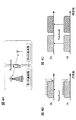
図1は、HetNetの概念図である。なお、図1Aはマクロセルとスモールセルとで同一の周波数帯を用いた場合を示し、図1Bはマクロセルとスモールセルとで異なる周波数帯を用いた場合を示している。 FIG. 1 is a conceptual diagram of HetNet. 1A shows a case where the same frequency band is used for the macro cell and the small cell, and FIG. 1B shows a case where different frequency bands are used for the macro cell and the small cell.
図1に示すように、HetNetは、マクロセルMとスモールセルSの少なくとも一部が地理的に重複して配置される無線通信システムである。また、HetNetは、マクロセルMを形成する無線基地局(以下、マクロ基地局という)と、スモールセルSを形成する無線基地局(以下、スモール基地局という)と、マクロ基地局とスモール基地局と通信するユーザ端末UEとを含んで構成される。 As shown in FIG. 1, HetNet is a wireless communication system in which at least a part of a macro cell M and a small cell S are geographically overlapped. HetNet includes a radio base station that forms a macro cell M (hereinafter referred to as a macro base station), a radio base station that forms a small cell S (hereinafter referred to as a small base station), a macro base station and a small base station, It is comprised including the user terminal UE which communicates.
図1Aに示す場合、マクロセルMとスモールセルSにおいて、例えば、800MHzや2GHz等の同一の周波数帯のキャリアを適用することができる。一方で、図1Bに示す場合、マクロセルMでは、例えば、800MHzや2GHzなど、相対的に低い周波数帯のキャリアが用いられる。一方、複数のスモールセルSでは、例えば、3.5GHzなど、相対的に高い周波数帯のキャリアが用いられる。 In the case shown in FIG. 1A, in the macro cell M and the small cell S, for example, carriers in the same frequency band such as 800 MHz and 2 GHz can be applied. On the other hand, in the case shown in FIG. 1B, in the macro cell M, a carrier having a relatively low frequency band such as 800 MHz or 2 GHz is used. On the other hand, in a plurality of small cells S, a carrier having a relatively high frequency band such as 3.5 GHz is used.
このように、LTE−A(Rel.12以降)の無線通信システムでは、スモールセルSとマクロセルMが同一周波数を適用するシナリオ(co-channel)に加えて、スモールセルSとマクロセルMが異なる周波数を適用するシナリオ(Separate frequency)が検討されている。 As described above, in the LTE-A (Rel. 12 or later) radio communication system, in addition to a scenario (co-channel) in which the small cell S and the macro cell M apply the same frequency, the small cell S and the macro cell M have different frequencies. A scenario (Separate frequency) is being studied.
また、スモールセルとマクロセルが異なる無線基地局で運用される場合、マクロ基地局(MeNB)とスモール基地局(SeNB)は、バックホールで接続されて相互に情報のやり取りを行う。マクロ基地局とスモール基地局間の接続は、光ファイバ(Optical fiber)や非光ファイバ(X2インターフェース)等の有線接続や、無線接続で行うことが考えられる。なお、マクロ基地局とスモール基地局間の接続を光ファイバ以外の回線(例えば、X2インターフェース)で行う場合には、マクロ基地局とスモール基地局間の情報の送受信において遅延時間が無視できなくなる。理想的には、バックホールの伝達遅延は0msecであるが、バックホールの環境によっては最大で伝達遅延が数10msecとなる場合がある。 When the small cell and the macro cell are operated in different radio base stations, the macro base station (MeNB) and the small base station (SeNB) are connected by backhaul and exchange information with each other. The connection between the macro base station and the small base station may be performed by a wired connection such as an optical fiber (Optical fiber) or a non-optical fiber (X2 interface), or a wireless connection. When the connection between the macro base station and the small base station is performed using a line (for example, X2 interface) other than the optical fiber, the delay time cannot be ignored in the transmission / reception of information between the macro base station and the small base station. Ideally, the transmission delay of the backhaul is 0 msec, but depending on the backhaul environment, the maximum transmission delay may be several tens of msec.
ところで、Rel.10/11で導入されたキャリアアグリゲーション(CA)と協調送信(CoMP)では、上述したように複数のCC又は複数の送受信ポイントを、1つの無線基地局に実装されたスケジューラで集中制御することを前提としている(図2A参照)。一方で、将来の無線通信システム(Rel.12以降)では、遅延の無視できないバックホールで接続された異なる無線基地局間におけるCAやCoMPをサポートする必要がある(図2B参照)。 By the way, Rel. In carrier aggregation (CA) and coordinated transmission (CoMP) introduced in 10/11, as described above, centralized control of a plurality of CCs or a plurality of transmission / reception points is performed by a scheduler installed in one radio base station. This is assumed (see FIG. 2A). On the other hand, in future wireless communication systems (Rel. 12 and later), it is necessary to support CA and CoMP between different wireless base stations connected by a backhaul whose delay cannot be ignored (see FIG. 2B).
このように、異なる無線基地局間におけるCAやCoMPをサポートするためには、各無線基地局で適切にスケジューリングを行う必要がある。各無線基地局でユーザ端末に送信する下りデータを下り共有チャネル(PDSCH)に適切にスケジューリングするためには、上りリンクでユーザ端末がフィードバック信号を適切に送信することが必要となる。フィードバック信号としては、下りデータ(PDSCH信号)の復号可否を示す送達確認信号(ACK/NACK)や、下り参照信号(CSI−RS)を用いて測定したチャネル品質情報(CSI)等がある。 Thus, in order to support CA and CoMP between different radio base stations, it is necessary to perform scheduling appropriately in each radio base station. In order to appropriately schedule downlink data to be transmitted to the user terminal in each radio base station to the downlink shared channel (PDSCH), it is necessary for the user terminal to appropriately transmit a feedback signal in the uplink. The feedback signal includes a delivery confirmation signal (ACK / NACK) indicating whether or not downlink data (PDSCH signal) can be decoded, channel quality information (CSI) measured using a downlink reference signal (CSI-RS), and the like.
LTE(Rel.8)では、上り共有チャネル(PUSCH)で上りデータ送信を指示する制御信号(ULグラント)が検出された場合、ユーザ端末はULグラントで割当てられたPUSCHのリソースを用いてフィードバック信号の送信を行う(図3参照)。一方で、ULグラントが検出されない場合、ユーザ端末は上り制御チャネル(PUCCH)を用いてフィードバック信号を送信する(図3参照)。つまり、ユーザ端末は、上りデータを送信する場合には、PUSCHを利用して上りデータと共にフィードバック信号を送信し、上りデータを送信しない場合には、PUCCHを利用してフィードバック信号を送信する。 In LTE (Rel. 8), when a control signal (UL grant) instructing uplink data transmission is detected on the uplink shared channel (PUSCH), the user terminal uses a PUSCH resource allocated by the UL grant to provide a feedback signal. Is transmitted (see FIG. 3). On the other hand, when the UL grant is not detected, the user terminal transmits a feedback signal using the uplink control channel (PUCCH) (see FIG. 3). That is, when transmitting uplink data, the user terminal transmits a feedback signal together with uplink data using PUSCH, and when not transmitting uplink data, the user terminal transmits a feedback signal using PUCCH.
異なる無線基地局間でCAやCoMPを適用する場合、各無線基地局で適切にスケジューリングを行うために、ユーザ端末はフィードバック信号を出来るだけ各無線基地局に直接送信することが望ましい(図4A〜4C参照)。しかし、Rel.10/11までのフィードバックメカニズムでは、CAを適用する際に、フィードバック信号を複数の無線基地局に対して別々に送信することが困難となる。以下に、Rel.10/11においてキャリアアグリゲーション(CA)を行う場合のフィードバック方法について図面を参照して説明する。なお、以下の説明では、上下リンクとも、1つのプライマリセル(PCell)と、1つ又は複数のセカンダリセル(SCell)がある場合を想定する。 When CA or CoMP is applied between different radio base stations, it is desirable for the user terminal to transmit a feedback signal directly to each radio base station as much as possible in order to perform appropriate scheduling in each radio base station (FIG. 4A to FIG. 4). 4C). However, Rel. In the feedback mechanism up to 10/11, when CA is applied, it is difficult to separately transmit feedback signals to a plurality of radio base stations. Below, Rel. A feedback method when carrier aggregation (CA) is performed in 10/11 will be described with reference to the drawings. In the following description, it is assumed that there is one primary cell (PCell) and one or a plurality of secondary cells (SCell) for both the upper and lower links.
上り制御チャネル(PUCCH)と上り共有チャネル(PUSCH)の同時送信が設定されていないユーザ端末は、ULグラントを検出しなかった場合、PCellのPUCCHを用いてフィードバック信号(送達確認信号、CSI等)を送信する(図5A参照)。一方で、ULグラントを検出した場合には、ULグラントを検出したセルのPUSCHを用いてフィードバック信号を上りデータと一緒に送信する。具体的に、ユーザ端末は、PCellでULグラントを検出した場合にはPCellのPUSCHを用いてフィードバックを行い(図5B参照)、SCellでULグラントを検出した場合にはSCellのPUSCHを用いてフィードバックを行う(図5C参照)。なお、複数のセルで同時にULグラントを検出した場合には、PCellのPUSCHを用いてフィードバックを行う。 If the user terminal in which simultaneous transmission of the uplink control channel (PUCCH) and the uplink shared channel (PUSCH) is not set does not detect the UL grant, a feedback signal (delivery confirmation signal, CSI, etc.) is used using the PUCCH of the PCell. Is transmitted (see FIG. 5A). On the other hand, when the UL grant is detected, the feedback signal is transmitted together with the uplink data using the PUSCH of the cell in which the UL grant is detected. Specifically, when the UL grant is detected by the PCell, the user terminal performs feedback using the PUell of the PCell (see FIG. 5B), and when the UL grant is detected by the SCell, the user terminal performs feedback using the PUell of the SCell. (See FIG. 5C). In addition, when UL grant is detected simultaneously in a plurality of cells, feedback is performed using the PUSCH of the PCell.
PUCCHとPUSCHの同時送信が設定されているユーザ端末は、ULグラントを検出しなかった場合、PCellのPUCCHを用いてフィードバック信号を送信する(上記図5A参照)。一方で、ULグラントを検出した場合には、PCellのPUCCH及び/又はPUSCHでフィードバックを行う。つまり、ULグラントを検出した場合であっても、一部のフィードバック信号(送達確認信号(ACK/NACK))をPUCCHを用いて(ULグラントで割当てられたPUSCHと同時に)送信する。 When the user terminal configured to simultaneously transmit PUCCH and PUSCH does not detect the UL grant, the user terminal transmits a feedback signal using the PUCCH of the PCell (see FIG. 5A above). On the other hand, when the UL grant is detected, feedback is performed using PUCCH and / or PUSCH of PCell. That is, even when the UL grant is detected, a part of the feedback signal (acknowledgment confirmation signal (ACK / NACK)) is transmitted using the PUCCH (at the same time as the PUSCH assigned by the UL grant).
なお、PUCCHとPUSCHの同時送信は、各ユーザ端末の能力(性能)に応じて無線基地局が適宜設定する。PUCCHとPUSCHの同時送信を行わないユーザ端末は、ULグラントの有無に関わらずシングルキャリア送信を行うため安価なRF回路で構成することができる。一方で、PUSCHと比較して冗長なPUCCHでは干渉や熱雑音に強く高い確率で信号を検出できるため、PUCCHとPUSCHの同時送信を行うユーザ端末は、PUCCHを利用してフィードバック信号を送信することによりフィードバック精度を向上することができる。 Note that simultaneous transmission of PUCCH and PUSCH is appropriately set by the radio base station according to the capability (performance) of each user terminal. A user terminal that does not perform simultaneous transmission of PUCCH and PUSCH performs single carrier transmission regardless of the presence or absence of UL grant, and can be configured with an inexpensive RF circuit. On the other hand, a redundant PUCCH can detect a signal with a high probability that it is more resistant to interference and thermal noise than a PUSCH. Therefore, a user terminal that transmits PUCCH and PUSCH simultaneously transmits a feedback signal using the PUCCH. Thus, feedback accuracy can be improved.
なお、各ユーザ端末がPUCCHとPUSCHの同時送信が可能であるか否かは、ユーザ端末の能力情報(UE Capability)として無線基地局に通知される。無線基地局は、各ユーザ端末の能力に基づいてPUCCHとPUSCHの同時送信の適用を適宜設定し、各ユーザ端末に対して上位レイヤシグナリング(例えば、RRCシグナリング)で指示する。 Note that whether or not each user terminal can simultaneously transmit PUCCH and PUSCH is reported to the radio base station as capability information (UE capability) of the user terminal. The radio base station appropriately sets application of simultaneous transmission of PUCCH and PUSCH based on the capability of each user terminal, and instructs each user terminal by higher layer signaling (for example, RRC signaling).
このように、Rel.10/11までのフィードバックメカニズムでは、ULグラントがない場合、SCell(例えば、スモールセル)のフィードバック信号はPCell(例えば、マクロセル)のPUCCHでフィードバックされる。通常、各無線基地局におけるスケジューリングは1ms(1サブフレーム)単位で行われるため、異なる基地局間のバックホールで遅延が無視できない場合には、無線基地局間の遅延の影響によりスループットが低下するおそれがある。また、SCellのフィードバック信号を全てPCellのPUCCHに割当てる場合、通信環境によってはPCellのPUCCHの容量が不足するおそれもある。 Thus, Rel. In the feedback mechanism up to 10/11, when there is no UL grant, the feedback signal of the SCell (eg, small cell) is fed back on the PUCCH of the PCell (eg, macro cell). Normally, scheduling at each radio base station is performed in units of 1 ms (1 subframe), and thus when the delay cannot be ignored in the backhaul between different base stations, the throughput decreases due to the delay between the radio base stations. There is a fear. Also, when all SCell feedback signals are allocated to the PCell PUCCH, the capacity of the PCell PUCCH may be insufficient depending on the communication environment.
そのため、フィードバック信号を各下りCC(セル)に対応する上りCCでフィードバックするために、ULグラントを送信して当該上りCCに対してPUSCHを割当てることが考えられる。例えば、ユーザ端末にフィードバック信号をSCellでフィードバックさせるために、上りデータが無い場合あってもSCellのULグラントを送信してPUSCHリソースを割当てることが考えられる。 Therefore, in order to feed back a feedback signal with an uplink CC corresponding to each downlink CC (cell), it is conceivable to transmit a UL grant and assign a PUSCH to the uplink CC. For example, in order to feed back a feedback signal to the user terminal using the SCell, even if there is no uplink data, it may be possible to allocate the PUSCH resource by transmitting the UL grant of the SCell.
しかし、このようにSCellの下りリンク信号でULグラントを送信してSCellのPUSCHリソースを用いてフィードバックを行う場合、同じタイミングでPCellのULグラントを送信できなくなる。これは、PCellのULグラントを検出した場合には、ユーザ端末がPCellのPUSCHでフィードバックを行うためである。 However, when the UL grant is transmitted using the downlink signal of the SCell and feedback is performed using the PUSCH resource of the SCell, the UL grant of the PCell cannot be transmitted at the same timing. This is because when a PCell UL grant is detected, the user terminal performs feedback on the PCell PUSCH.
また、ユーザ端末がULグラントを検出できない場合(検出ミスの場合)には、PUSCHを用いてフィードバックすることができず、意図しないCC(セル)のPUCCHでフィードバックされるおそれがある。例えば、上記図5B、5Cにおいて、ユーザ端末がULグラントを検出できない場合には、フィードバック信号がPCellの上り制御チャネル(PUCCH)でフィードバックされてしまう(図6A〜6C参照)。 Further, when the user terminal cannot detect the UL grant (in the case of a detection error), feedback cannot be performed using the PUSCH, and there is a possibility that feedback is performed using the unintended CC (cell) PUCCH. For example, in FIGS. 5B and 5C, when the user terminal cannot detect the UL grant, the feedback signal is fed back on the uplink control channel (PUCCH) of the PCell (see FIGS. 6A to 6C).
このように、SCellのULグラントを利用して、フィードバック信号をSCellのPUSCHを利用してフィードバックさせると、PCellのULグラント送信が制限される問題や、ULグラント検出ミスの際に適切にフィードバックできない問題が生じる。一方で、このような問題を解決するために、SCellにおいてもPCellと同様に、上りリンクでPUCCHを利用することが考えられる。つまり、ULグラントを検出しない場合、ユーザ端末は各セル個別のフィードバック信号をそれぞれ各セルのPUCCHで送信する(図7A参照)。そして、ULグラントを検出した場合、ユーザ端末は各セル個別のフィードバック信号をそれぞれ各セルのPUSCHで送信することが考えられる(図7B、7C参照)。 As described above, when the feedback signal is fed back using the SCell's UL grant using the SCell's UL grant, it is not possible to appropriately feed back the problem of limiting the UL grant detection of the PCell or the UL grant detection error. Problems arise. On the other hand, in order to solve such a problem, it is conceivable to use PUCCH in the uplink in SCell as well as PCell. That is, when the UL grant is not detected, the user terminal transmits a feedback signal for each cell on the PUCCH of each cell (see FIG. 7A). And when UL grant is detected, it is possible that a user terminal transmits the feedback signal specific to each cell by PUSCH of each cell (refer FIG. 7B and 7C).
図7に示すフィードバック方法を適用することにより、セル個別のフィードバックは実現することが可能となる。しかし、ユーザ端末は別々にフィードバックする全ての上りCCにおいてPUCCHで送信できることが必要となるため、ユーザ端末の回路構成が複雑となりコストが増大する問題がある。また、無線基地局間CoMP(Inter−eNB CoMP)の場合や、下りリンクのみ無線基地局間CA(Inter−eNB CA)の場合(上りリンクは1CCでCAを行わない場合)には、上りリンクにおいてSCellが存在しないため、別の解決方法が新たに必要となる。その結果、更なる技術の実装が必要となってしまう。 By applying the feedback method shown in FIG. 7, it is possible to realize feedback for each cell. However, since the user terminal needs to be able to transmit on the PUCCH in all uplink CCs that are fed back separately, there is a problem that the circuit configuration of the user terminal becomes complicated and the cost increases. Further, in the case of inter-radio base station CoMP (Inter-eNB CoMP), or in the case of downlink-only CA between radio base stations (inter-eNB CA) (in the case where CA is not performed with 1 CC in the uplink), the uplink Since there is no SCell, another solution is newly required. As a result, further technology implementation is required.
そこで、本発明者等は、上記問題点に着目して、SCellに対するフィードバック信号を、ULグラントの有無に関わらずPUSCHを用いてフィードバックすることを着想した。特に本発明者等は、マクロ基地局とスモール基地局間でCAを適用する場合に、スモールセル(SCell)ではマクロセル(PCell)と比較して接続ユーザ端末数が少なくリソース容量に余裕がある点に着目し、SCellに対するフィードバック信号をULグラントの有無に関わらずSCellのPUSCHを用いて行うことを見出した。 Therefore, the present inventors have focused on the above problem and have come up with the idea of feeding back the feedback signal for the SCell using the PUSCH regardless of the presence or absence of the UL grant. In particular, when applying CA between a macro base station and a small base station, the present inventors have a small number of connected user terminals in a small cell (SCell) compared to a macro cell (PCell), and have a sufficient resource capacity. It was found that the feedback signal for the SCell is performed using the PUSCH of the SCell regardless of the presence or absence of the UL grant.
また、本発明者等は、SCellに対するフィードバック信号を、ULグラントの有無に関わらずPUSCHを用いて行う際に、新たなPUSCHリソース割当て方法を着想した。具体的には、SCellでULグラントの有無に応じてPUSCHのリソース割当てを変更し、例えば、ユーザ端末がULグラントを検出しない場合に、下り制御情報(DL assignment)を利用してPUSCHリソースの割当てを行うことを着想した。 In addition, the present inventors have conceived a new PUSCH resource allocation method when performing feedback signals for SCells using PUSCH regardless of the presence or absence of UL grant. Specifically, PUSCH resource allocation is changed according to the presence or absence of UL grant in SCell. For example, when the user terminal does not detect UL grant, PUSCH resource allocation using downlink control information (DL assignment) is performed. Inspired to do.
以下に、本実施の形態について添付図面を参照して詳細に説明する。なお、以下の説明では、マクロ基地局とスモール基地局間のCoMP及び/又はCA(Inter−eNB CoMP/CA)を例に挙げて説明するが、本実施の形態はこれに限られず異なる無線基地局間の制御であれば適用することができる。また、以下の説明では、マクロセルをPCell、スモールセルをSCellとして説明するが、本実施の形態はこれに限られない。 Hereinafter, the present embodiment will be described in detail with reference to the accompanying drawings. In the following description, CoMP and / or CA (Inter-eNB CoMP / CA) between a macro base station and a small base station will be described as an example. However, the present embodiment is not limited to this and different radio base stations Any control between stations can be applied. In the following description, the macro cell is described as PCell, and the small cell is described as SCell, but the present embodiment is not limited to this.
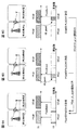
(第1の態様)
図8は、第1の基地局と第2の基地局間でCAを適用する場合において、上りリンクのフィードバック方法の一例について示している。なお、図8では、第1の基地局がマクロセル(PCell)を形成し、第2の基地局がスモールセル(SCell)を形成する場合を示している。具体的に、図8AはPCell及びSCellの下りリンク信号にULグラントが含まれていない場合に相当し、図8BはPCellの下りリンク信号のみにULグラントが含まれている場合に相当し、図8CはSCellの下りリンク信号のみにULグラントが含まれている場合に相当する。
(First aspect)
FIG. 8 shows an example of an uplink feedback method when CA is applied between the first base station and the second base station. FIG. 8 illustrates a case where the first base station forms a macro cell (PCell) and the second base station forms a small cell (SCell). Specifically, FIG. 8A corresponds to the case where the UL grant is not included in the PCell and SCell downlink signals, and FIG. 8B corresponds to the case where the UL grant is included only in the PCell downlink signal. 8C corresponds to the case where UL grant is included only in the downlink signal of SCell.
図8Aに示すように、PCell及びSCellの下りリンク信号にULグラントが含まれていない場合、ユーザ端末はPCellの下りリンク信号に対するフィードバック信号をPCellの上り制御チャネル(PUCCH)を用いてフィードバックする。一方で、ユーザ端末はSCellの下りリンク信号に対するフィードバック信号をSCellの上り共有チャネル(PUSCH)を用いてフィードバックする。この場合、SCellのフィードバック信号を割当てるPUSCHリソースは、無線基地局(例えば、マクロ基地局)から上位レイヤシグナリング等で指示することができる。 As shown in FIG. 8A, when the UL grant is not included in the downlink signals of PCell and SCell, the user terminal feeds back a feedback signal for the downlink signal of PCell using the uplink control channel (PUCCH) of PCell. On the other hand, the user terminal feeds back a feedback signal for the downlink signal of the SCell using the uplink shared channel (PUSCH) of the SCell. In this case, the PUSCH resource to which the SCell feedback signal is allocated can be instructed by higher layer signaling or the like from a radio base station (for example, a macro base station).
図8Bに示すように、PCellの下りリンク信号のみにULグラントが含まれている場合、ユーザ端末はPCellの下りリンク信号に対するフィードバック信号をPCellのPUSCHを用いてフィードバックする。また、SCellの下りリンク信号に対するフィードバック信号をSCellのPUSCHを用いてフィードバックする。この場合、SCellのフィードバック信号を割当てるPUSCHリソースは、無線基地局(例えば、マクロ基地局)から上位レイヤシグナリング等で指示することができる。 As illustrated in FIG. 8B, when the UL grant is included only in the PCell downlink signal, the user terminal feeds back a feedback signal for the PCell downlink signal using the PCell PUSCH. In addition, a feedback signal for the downlink signal of the SCell is fed back using the PUSCH of the SCell. In this case, the PUSCH resource to which the SCell feedback signal is allocated can be instructed by higher layer signaling or the like from a radio base station (for example, a macro base station).
図8Cに示すように、SCellの下りリンク信号のみにULグラントが含まれている場合、ユーザ端末はPCellの下りリンク信号に対するフィードバック信号をPCellのPUCCHを用いてフィードバックする。また、SCellの下りリンク信号に対するフィードバック信号をSCellのPUSCHを用いてフィードバックする。この場合、SCellのフィードバック信号を割当てるPUSCHリソースは、ULグラントで指示することができる。 As illustrated in FIG. 8C, when the UL grant is included only in the SCell downlink signal, the user terminal feeds back a feedback signal for the PCell downlink signal using the PCell PUCCH. In addition, a feedback signal for the downlink signal of the SCell is fed back using the PUSCH of the SCell. In this case, the PUSCH resource to which the SCell feedback signal is allocated can be indicated by the UL grant.
このように、SCellの下りリンク信号に対するフィードバック情報を、ULグラントの有無に関わらずPUSCHを利用してフィードバックすることにより、Rel.10/11における上り同時送信・非同時送信で全ての送信パターンをサポートすることができる。これにより、ユーザ端末に対してRel.10/11までの回路を利用することができるため、ユーザ端末の製造コストを抑制することが可能となる。また、ユーザ端末がSCellからのULグラントを検出できなかった場合(検出ミスの場合)であっても、SCellに対するフィードバック信号をSCellに直接フィードバックすることができる。 As described above, feedback information about the downlink signal of the SCell is fed back using the PUSCH regardless of the presence or absence of the UL grant. All transmission patterns can be supported by simultaneous uplink / non-simultaneous transmission in 10/11. As a result, Rel. Since a circuit up to 10/11 can be used, the manufacturing cost of the user terminal can be suppressed. Moreover, even if it is a case where a user terminal cannot detect UL grant from SCell (in the case of a detection mistake), the feedback signal with respect to SCell can be directly fed back to SCell.
また、上記図8で示したフィードバック方法は、無線基地局間CoMPを適用する場合や、下りリンクのみ無線基地局間CAを適用する場合(上りリンクはPCellのみ設定される場合)にも適用することができる(図9A〜9C)。 Further, the feedback method shown in FIG. 8 is also applied to the case where CoMP between radio base stations is applied, or the case where CA between radio base stations is applied only to the downlink (when only the PCell is set for the uplink). (FIGS. 9A-9C).
例えば、第1の基地局と第2の基地局が同一の周波数で運用される場合、ユーザ端末は、PCellに対するフィードバック信号をPCellのPUCCHを用いてフィードバックする。一方で、ユーザ端末は、SCellに対するフィードバック信号をPCellのPUSCHを用いてフィードバックする(図9B参照)。 For example, when the first base station and the second base station are operated at the same frequency, the user terminal feeds back a feedback signal for the PCell using the PUCCH of the PCell. On the other hand, the user terminal feeds back a feedback signal for the SCell using the PUSCH of the PCell (see FIG. 9B).
また、第1の基地局と第2の基地局が異なる周波数で運用される場合においても、ユーザ端末は、PCellに対するフィードバック信号をPCellのPUCCHを用いてフィードバックする。一方で、ユーザ端末は、SCellに対するフィードバック信号をPCellのPUSCHを用いてフィードバックする(図9C参照)。 Even when the first base station and the second base station are operated at different frequencies, the user terminal feeds back a feedback signal for the PCell using the PUCCH of the PCell. On the other hand, the user terminal feeds back a feedback signal for the SCell using the PUSCH of the PCell (see FIG. 9C).
上記図7で示したように、SCellに対してもPUCCHを設定する方法では、無線基地局間CoMPや下りリンクのみ無線基地局間CAを適用する場合に異なるフィードバック方法を新たに適用する必要があった。しかし、上記図9で示すフィードバック方法では、基地局間CoMPや下りリンクのみ基地局間CAを適用する場合であっても、同様のフィードバックメカニズムを適用することができる。 As shown in FIG. 7 above, in the method of setting PUCCH also for SCell, it is necessary to newly apply a different feedback method when applying CoMP between radio base stations or CA between radio base stations only in the downlink. there were. However, in the feedback method shown in FIG. 9, the same feedback mechanism can be applied even when inter-base station CoMP or inter-base station CA is applied only to the downlink.
上りリンク信号の送信電力制御においてLTE.10/11では、PUCCHとPUSCHとで独立に送信電力を制御すると共に、PCellとSCell間でも独立に送信電力を制御する。したがって、上記図9で示すように、SCellに対するフィードバック信号をPUSCHリソースに割当てることにより、LTE.10/11の送信電力制御の仕組みをそのまま利用することができる。 In the uplink signal transmission power control, LTE. In 10/11, transmission power is controlled independently by PUCCH and PUSCH, and transmission power is also controlled independently between PCell and SCell. Therefore, as shown in FIG. 9 above, by assigning a feedback signal for SCell to a PUSCH resource, LTE. The 10/11 transmission power control mechanism can be used as it is.
例えば、第2の基地局(スモール基地局)の近傍に位置するユーザ端末は、PCell及びSCellの下りリンク信号にULグラントが含まれていない場合(上記図8A参照)、PCellのPUCCHと、SCellのPUSCHの送信電力をそれぞれ制御することができる(図10A参照)。同様に、無線基地局間CoMPを適用する場合や、下りリンクのみ無線基地局間CAを適用する場合においても、PUCCHとPUSCHの送信電力をそれぞれ独立して制御することができる(図10B、10C参照)。 For example, the user terminal located in the vicinity of the second base station (small base station), when the UL grant is not included in the downlink signals of the PCell and SCell (see FIG. 8A above), the PUCCH of the PCell and the SCell The transmission power of each PUSCH can be controlled (see FIG. 10A). Similarly, when applying inter-radio base station CoMP or applying inter-radio base station CA only in the downlink, the transmission power of PUCCH and PUSCH can be controlled independently (FIGS. 10B and 10C). reference).
このように、本実施の形態のフィードバック方法を用いることにより、ユーザ端末がいずれかの無線基地局(例えば、スモール基地局)に近く、複数の無線基地局との間で伝播損失(パスロス)が異なる場合であっても、適切な送信電力を設定してフィードバックを行うことが可能となる。 Thus, by using the feedback method of the present embodiment, the user terminal is close to any one of the radio base stations (for example, a small base station), and the propagation loss (path loss) between the plurality of radio base stations is increased. Even if they are different, it is possible to perform feedback by setting an appropriate transmission power.
ここで、無線基地局間CAで本実施の形態のフィードバック方法を適用する場合に、フィードバックを行いたいCC(セル)と、利用するフィードバック用チャネルについて図11、図12を参照して説明する。なお、図11、図12では、本実施の形態のフィードバック方法(提案例)と、従来のフィードバック方法と、上記図7に示したSCellのPUCCHを利用するフィードバック方法(検討例)と、を比較して記載している。 Here, when the feedback method of the present embodiment is applied in the CA between radio base stations, a CC (cell) to be fed back and a feedback channel to be used will be described with reference to FIG. 11 and FIG. 11 and 12, the feedback method of the present embodiment (proposed example), the conventional feedback method, and the feedback method using the SCell's PUCCH shown in FIG. 7 (study example) are compared. It is described as.
なお、図11(例1)と図12(例2)との違いは、提案法において、PCellとSCellから同時にULグラントがある場合に、PCellのPUCCH利用の有無に関する点である。具体的に、図11(例1)は、検討例、提案例ともに従来法の「同時送信なし」から拡張した場合を示しており、出来るだけ少ない同時送信数で送信を行うことができる。これにより、ユーザ端末のRF回路の負担を低減して電力効率を向上することが可能となる。 The difference between FIG. 11 (Example 1) and FIG. 12 (Example 2) lies in the presence or absence of PCell PUCCH usage when there is a UL grant from PCell and SCell simultaneously in the proposed method. Specifically, FIG. 11 (example 1) shows a case in which both the examination example and the proposed example are extended from the “no simultaneous transmission” of the conventional method, and transmission can be performed with as few simultaneous transmissions as possible. As a result, it is possible to reduce the burden on the RF circuit of the user terminal and improve the power efficiency.
また、図12(例2)は、検討例、提案例ともに従来法の「同時送信あり」から拡張した場合を示している。例2の検討例では、フィードバックをPCell及びSCellともに出来るだけPUCCHで行う、つまりSCellであってもPUCCHでフィードバックする場合を示している。また、例2の提案法では、PCellのフィードバックを出来るだけPUCCHを行う場合を示している。一方で、SCellはULグラントの有無に関わらずPUSCHでフィードバックを行う。このように、接続を維持すべきPCell(例えば、マクロセル)において出来るだけPUCCHを利用してフィードバックを行うことにより、フィードバック信号の品質を確保することができる。 Further, FIG. 12 (example 2) shows a case where both the examination example and the proposal example are extended from the conventional method “with simultaneous transmission”. The examination example of Example 2 shows a case where feedback is performed on the PCell and SCell as much as possible on the PUCCH, that is, even on the SCell, feedback is performed on the PUCCH. Further, the proposed method of Example 2 shows a case where PUCCH is performed as much as possible for PCell feedback. On the other hand, SCell performs feedback on PUSCH regardless of the presence or absence of UL grant. Thus, the quality of the feedback signal can be ensured by performing feedback using the PUCCH as much as possible in the PCell (for example, macro cell) that should maintain the connection.
<無線基地局間CoMP>
無線基地局間CoMPでは、無線基地局間が同一周波数で運用されるため、PCell、SCellの区別は無い。したがって、無線基地局間CAのように異なる基地局に対して別々にフィードバックを行うためには、単一のCell内でフィードバックリソース(PUCCH又はPUSCH)を変える必要がある。すなわちユーザ端末は、受信した下りリンク信号に対するフィードバック先の無線基地局を判別し、いずれの基地局から下りデータが送信されたかに応じて、送達確認信号(ACK/NACK)のフィードバックリソースを変えなければならない。ところが上述したように、無線基地局間CoMPでは無線基地局間が同一周波数で運用されるため、ユーザ端末は、無線基地局間CAのようにフィードバック先を容易に判断することが困難となる。
<CoMP between radio base stations>
In CoMP between radio base stations, since radio base stations are operated at the same frequency, there is no distinction between PCell and SCell. Therefore, in order to perform feedback separately for different base stations such as CA between radio base stations, it is necessary to change feedback resources (PUCCH or PUSCH) within a single cell. That is, the user terminal must determine the feedback base station for the received downlink signal, and change the feedback resource of the acknowledgment signal (ACK / NACK) depending on which base station has transmitted the downlink data. I must. However, as described above, in CoMP between radio base stations, radio base stations are operated at the same frequency. Therefore, it is difficult for a user terminal to easily determine a feedback destination as in CA between radio base stations.
そこで、本実施の形態においてユーザ端末は、無線基地局間CAの場合と同様に第2の基地局(スモール基地局)に対するフィードバックを行う場合にはPUSCHによりフィードバックするものとし、フィードバックする無線基地局を、無線基地局から通知される上位レイヤシグナリング又は下り制御情報(DL assignment)に基づいて決定する。 Thus, in the present embodiment, the user terminal, when performing feedback to the second base station (small base station) as in the case of CA between the radio base stations, feeds back using PUSCH, and feeds back the radio base station. Is determined based on upper layer signaling or downlink control information (DL assignment) notified from the radio base station.
例えば、ユーザ端末は、あらかじめマクロ基地局に対するフィードバックはPUCCHで送信し、スモール基地局に対するフィードバックは、あらかじめRRCシグナリング等の上位レイヤで通知されたPUSCHリソースで送信する。このようにすることで、無線基地局間CoMPを行う複数の無線基地局に対して異なるリソースを用いて別々にフィードバックを行うことができる。また、例えば2つの無線基地局に同時にフィードバックする場合であっても、同一CC内でのPUCCHとPUSCHの同時送信になるため、Rel.10/11で既に導入された上り回線の同時送信の回路構成で実現できるため、コストの増加を抑制できるというメリットがある。 For example, the user terminal transmits the feedback to the macro base station in advance using PUCCH, and the feedback to the small base station is transmitted using the PUSCH resource notified in advance in the upper layer such as RRC signaling. By doing in this way, it is possible to separately feed back a plurality of radio base stations performing CoMP between radio base stations using different resources. Further, for example, even when feedback is simultaneously provided to two radio base stations, since PUCCH and PUSCH are simultaneously transmitted within the same CC, Rel. Since it can be realized by the circuit configuration of uplink simultaneous transmission already introduced in 10/11, there is an advantage that an increase in cost can be suppressed.
また、ユーザ端末は、下り共有チャネル(PDSCH)のスケジューリング情報を通知する下り制御信号(DL assignment)を検出したときに、送達確認信号のフィードバックを行う。したがって、ユーザ端末は、DL assignmentに基づいて、フィードバックする無線基地局を判断することも可能である。つまり、上位レイヤから無線基地局間CoMPが設定されたユーザ端末は、受信したDL assignmentに対応する制御チャネルの種類(PDCCH又は拡張PDCCH)や設定(例えば制御信号フォーマット(DCI format)、Aggregation levelなど)に基づいてフィードバックする無線基地局を判断することができる。又は、ユーザ端末は、受信したDL assignmentに含まれるビットに基づいてフィードバックすべき無線基地局を判断することができる。 Further, when detecting a downlink control signal (DL assignment) for reporting scheduling information of the downlink shared channel (PDSCH), the user terminal performs feedback of a delivery confirmation signal. Therefore, the user terminal can also determine the radio base station to be fed back based on the DL assignment. That is, the user terminal in which CoMP between radio base stations is set from the upper layer, the type (PDCCH or extended PDCCH) and setting (for example, control signal format (DCI format), aggregation level, etc.) corresponding to the received DL assignment ) To determine a radio base station to be fed back. Alternatively, the user terminal can determine the radio base station to be fed back based on the bits included in the received DL assignment.
<フィードバック動作>
次に、異なる無線基地局間でCoMP/CAを適用する場合のユーザ端末と無線基地局との通信方法の動作手順の一例について図13を参照して説明する。なお、ここでは、図13Aに示すように、第1の基地局(マクロ基地局)と第2の基地局(スモール基地局)と、第1の基地局及び第2の基地局に接続するユーザ端末を例に挙げて説明する。
<Feedback action>
Next, an example of an operation procedure of a communication method between a user terminal and a radio base station when CoMP / CA is applied between different radio base stations will be described with reference to FIG. Here, as shown in FIG. 13A, the first base station (macro base station), the second base station (small base station), and the user connected to the first base station and the second base station. A terminal will be described as an example.
まず、ユーザ端末は、当該ユーザ端末の能力(UE Capability)について無線基地局(例えば、マクロ基地局)に通知する(ステップ11)。これにより、無線基地局はユーザ端末が同時送信可能であるか否か、本実施の形態におけるフィードバック方法を適用できるか否かを判断することができる。 First, a user terminal notifies a radio base station (for example, a macro base station) about the capability (UE Capability) of the user terminal (step 11). Thereby, the radio base station can determine whether or not the user terminal can simultaneously transmit, and whether or not the feedback method in the present embodiment can be applied.
また、無線基地局は、ユーザ端末から通信品質に関する報告を受信すると共に、ユーザ端末が送信した信号の受信電力を測定する(ステップ12)。例えば、第1の基地局及び第2の基地局は、下り受信電力や受信品質(RSRP、RSRQ)の報告情報や、チャネル状態(CSI)報告情報等の受信品質情報をユーザ端末から受信する。また、第1の基地局及び第2の基地局は、上りサウンディング参照信号(SRS)やランダムアクセス(PRACH)の受信電力等を測定する。これにより、第1の基地局及び第2の基地局は、各ユーザ端末のチャネル状態や、位置(ユーザ端末がいずれの無線基地局が運用するセル(又は送信ポイント)に近いかどうか)を判断することができる。 In addition, the radio base station receives a report on communication quality from the user terminal and measures the received power of the signal transmitted by the user terminal (step 12). For example, the first base station and the second base station receive reception quality information such as downlink reception power and reception quality (RSRP, RSRQ) report information and channel state (CSI) report information from the user terminal. In addition, the first base station and the second base station measure uplink sounding reference signal (SRS), random access (PRACH) reception power, and the like. As a result, the first base station and the second base station determine the channel state and location of each user terminal (whether the user terminal is close to the cell (or transmission point) operated by which radio base station). can do.
次に、第1の基地局及び第2の基地局は、各無線基地局間で受信した情報についてバックホールを介して共有する(ステップ13)。例えば、各無線基地局は、自セル内のトラフィック情報や接続するユーザ端末情報についてバックホールを介して他の無線基地局と共有する。これにより、無線基地局(例えば、マクロ基地局)は、各ユーザ端末に対する無線基地局間CoMP/CAの適用有無を判断することができる。 Next, the first base station and the second base station share information received between the radio base stations via the backhaul (step 13). For example, each radio base station shares traffic information in its own cell and user terminal information to be connected with other radio base stations via the backhaul. Thereby, a radio base station (for example, a macro base station) can determine whether or not to apply CoMP / CA between radio base stations to each user terminal.
各ユーザ端末の状況に基づいて、無線基地局(例えば、マクロ基地局)はCoMP/CAの設定(Configure)を行う。ここでは、第1の基地局が、ユーザ端末に対して、無線基地局間CoMP/CAを設定する場合を想定する(ステップ14)。 Based on the situation of each user terminal, a radio base station (for example, a macro base station) performs CoMP / CA setting (Configure). Here, it is assumed that the first base station sets up inter-radio base station CoMP / CA for the user terminal (step 14).
この場合、第1の基地局は、ユーザ端末が第2の基地局(スモール基地局)と通信を行うための制御情報を上位レイヤシグナリング(例えば、RRCシグナリング)を介して通知する(ステップ15)。なお、ステップ14とステップ15は同時に行ってもよい。ユーザ端末に通知する制御情報としては、第2の基地局からの信号を受信するためのConfigurationや、第2の無線基地局へフィードバック信号を送信する際に利用するPUSCHリソース情報が含まれる。
In this case, the first base station notifies control information for the user terminal to communicate with the second base station (small base station) via higher layer signaling (for example, RRC signaling) (step 15). .
また、ユーザ端末に通知する制御情報としては、SCellの上りリンクにおけるフィードバックルール(既存のフィードバック方法の適用又は本実施の形態のフィードバック方法の適用)を指示する情報を含めてもよい。これにより、無線基地局間CoMP/CAを適用する場合であっても、ユーザ端末毎に適用するフィードバック方法を制御することができる。その結果、例えば、スモールセル(SCell)のPUSCHのトラフィックが多い場合には従来のフィードバック方法をそのまま適用する等、通信環境に応じて柔軟にフィードバック方法を制御することが可能となる。また、無線基地局間CoMP/CAの通知やフィードバックルールの選択指示の通知は、ユーザ端末毎に個別に行ってもよいし、セル内の全ユーザ端末に共通に行ってもよい。 Further, the control information notified to the user terminal may include information instructing feedback rules (application of the existing feedback method or application of the feedback method of the present embodiment) in the uplink of the SCell. Thereby, even if it is a case where CoMP / CA between radio base stations is applied, the feedback method applied for every user terminal can be controlled. As a result, for example, when the PUSCH traffic of a small cell (SCell) is large, the feedback method can be flexibly controlled according to the communication environment, such as applying the conventional feedback method as it is. Further, the notification of CoMP / CA between radio base stations and the notification of the feedback rule selection instruction may be performed individually for each user terminal, or may be performed in common for all user terminals in the cell.
そして、各無線基地局は、ユーザ端末に対して下りリンク信号を送信する(ステップ16)。ユーザ端末は、無線基地局(例えば、第1の基地局)から受信した制御情報に基づいて、第1の基地局及び第2の基地局が送信する制御チャネル(PDCCH、拡張PDCCH(EPDCCH))をモニタリングする。そして、ユーザ端末は、受信した下りリンク信号に対するフィードバック信号(送達確認信号、CSI等)を各無線基地局にフィードバックする(ステップ17)。 Each radio base station transmits a downlink signal to the user terminal (step 16). The user terminal transmits a control channel (PDCCH, extended PDCCH (EPDCCH)) transmitted from the first base station and the second base station based on control information received from a radio base station (for example, the first base station). To monitor. Then, the user terminal feeds back a feedback signal (delivery confirmation signal, CSI, etc.) for the received downlink signal to each radio base station (step 17).
本実施の形態のフィードバック方法を適用するユーザ端末は、第1の無線基地局からの下りリンク信号に対するフィードバック信号を、PCellのPUCCH又はPUSCHを利用してフィードバックする。具体的には、ユーザ端末は、第1の基地局に対して送信すべき上りデータが割当てられた場合(ULグラントを検出した場合)に限り、ULグラントで割当てられたPUSCHリソースにフィードバック信号を含めて送信する(上記図8B参照)。それ以外は、ユーザ端末は、PCellのPUCCHリソースを用いてフィードバックを行う(上記図8A、8C参照)。 A user terminal to which the feedback method of the present embodiment is applied feeds back a feedback signal for a downlink signal from the first radio base station using PUCCH or PUSCH of PCell. Specifically, the user terminal sends a feedback signal to the PUSCH resource allocated by the UL grant only when uplink data to be transmitted to the first base station is allocated (when the UL grant is detected). Including the transmission (see FIG. 8B above). Otherwise, the user terminal performs feedback using the PUCCH resource of the PCell (see FIGS. 8A and 8C above).
また、ユーザ端末は、第2の無線基地局からの下りリンク信号に対するフィードバック信号を、ULグラントの有無に関わらずPUSCHを用いてフィードバックする。具体的に、ユーザ端末は、第2の基地局に対して送信すべき上りデータが割当てられない場合(ULグラントを検出しなかった場合)、上位レイヤから通知されたPUSCHリソースを利用してフィードバックを行う(上記図8B参照)。ユーザ端末は、ULグラントを検出した場合に限り、ULグラントで割当てられたPUSCHリソースにフィードバック信号を含めて送信する(上記図8C参照)。 Further, the user terminal feeds back a feedback signal for the downlink signal from the second radio base station using PUSCH regardless of the presence or absence of the UL grant. Specifically, when the uplink data to be transmitted is not allocated to the second base station (when the UL grant is not detected), the user terminal performs feedback using the PUSCH resource notified from the higher layer. (See FIG. 8B above). Only when the UL grant is detected, the user terminal transmits the PUSCH resource allocated by the UL grant including the feedback signal (see FIG. 8C above).
このように、SCellに対するフィードバック信号をULグラントの有無に関わらずPUSCHを用いてフィードバックすることにより、Rel.10/11で規定されたPUCCHとPUSCHの同時送信・非同時送信の送信パターンをサポートすることができる。また、無線基地局間CoMPや、下りのみ無線基地局間CAにおいてもフィードバックメカニズムを適用できると共に、PUCCHとPUSCH間、及びPCellとSCell間において送信電力を独立して制御(既存の送信電力制御の仕組みを利用)することができる。 Thus, by feeding back the feedback signal for SCell using PUSCH regardless of the presence or absence of UL grant, Rel. The transmission pattern of simultaneous transmission / non-simultaneous transmission of PUCCH and PUSCH specified by 10/11 can be supported. In addition, the feedback mechanism can be applied to CoMP between radio base stations and CA between radio base stations only in downlink, and transmission power is controlled independently between PUCCH and PUSCH, and between PCell and SCell (existing transmission power control). Use the mechanism).
(第2の態様)
第2の態様では、上記第1の態様においてSCellの下りリンク信号に対するフィードバック信号の割当てを行うPUSCHリソースの設定・通知方法について説明する。
(Second aspect)
In the second aspect, a PUSCH resource setting / notification method for assigning a feedback signal to the downlink cell SCell in the first aspect will be described.
第1の態様において、第2の無線基地局(スモール基地局)へのフィードバックに利用するPUSCHリソースは、ULグラントの検出有無によって変化する。例えば、ユーザ端末がULグラントを検出した場合、ULグラントで指定された上りデータ送信リソース(PUSCHリソース)を利用して上りデータと共にフィードバックする。一方で、ユーザ端末がULグラントを検出しなかった場合には、上位レイヤで設定されたフィードバック用リソース(PUSCH)を利用してフィードバック信号を送信する。 In the first aspect, the PUSCH resource used for feedback to the second radio base station (small base station) varies depending on whether or not a UL grant is detected. For example, when the user terminal detects the UL grant, it feeds back with the uplink data using the uplink data transmission resource (PUSCH resource) specified by the UL grant. On the other hand, when the user terminal does not detect the UL grant, a feedback signal is transmitted using a feedback resource (PUSCH) set in an upper layer.
ところで、上記図6に示したように、ユーザ端末はULグラントの検出を失敗する可能性がある。このため、第2の無線基地局では上位レイヤで指定したフィードバック用のPUSCHリソースを他のユーザ端末に割当てることができない。仮に、フィードバック用のPUSCHリソースを他のユーザ端末にも割当てると、当該ユーザ端末がULグラントの検出を失敗したときに、他のユーザ端末と同一のPUSCHリソースを用いて同時に送信することとなる。その結果、異なるユーザ端末間でPUSCHの衝突が発生し、結果的に再送回数が増加することによりスループットが低下するおそれがある。 By the way, as shown in the said FIG. 6, a user terminal may fail the detection of UL grant. For this reason, the second radio base station cannot allocate the PUSCH resource for feedback designated in the higher layer to other user terminals. If the PUSCH resource for feedback is also allocated to another user terminal, when the user terminal fails to detect the UL grant, it is transmitted simultaneously using the same PUSCH resource as the other user terminal. As a result, a PUSCH collision occurs between different user terminals, and as a result, the number of retransmissions may increase, resulting in a decrease in throughput.
一方で、PUSCHの衝突を抑制するため、上位レイヤで指定したフィードバック用のPUSCHリソースを他のユーザ端末に割当てない場合には、PUSCHスケジューリングが制約され、リソースの利用効率を十分に図ることができなくなる。 On the other hand, if the PUSCH resource for feedback specified in the upper layer is not allocated to other user terminals in order to suppress the collision of PUSCH, PUSCH scheduling is restricted, and resource utilization efficiency can be sufficiently achieved. Disappear.
そこで、本発明者等は、高い頻度でフィードバックされる可能性がある送達確認信号(ACK/NACK)において、ユーザ端末がフィードバック前に下りPDSCHの受信を指示する下り制御情報(DL assignment)を検出することに着目し、当該下り制御情報をPUSCHリソース割当て・指示に利用することを見出した。さらに、本発明者等は、下り制御情報の中で、新たなフィードバック方法を適用する場合に、第2の無線基地局からのDL assignmentで使用されなくなるビットをPUSCHリソース指示に用いることを見出した。DL assignmentで使用されなくなるビットとしては、フィードバックに使用するPUCCHリソースの指示に用いられていたARIやARO(各2ビット)等が挙げられる。 Therefore, the present inventors detect downlink control information (DL assignment) instructing the user terminal to receive downlink PDSCH before feedback in an acknowledgment signal (ACK / NACK) that may be fed back frequently. In particular, the present inventors have found that the downlink control information is used for PUSCH resource allocation / instruction. Furthermore, the present inventors have found that, in the downlink control information, when a new feedback method is applied, a bit that is no longer used in the DL assignment from the second radio base station is used for PUSCH resource indication. . Examples of bits that are no longer used in DL assignment include ARI and ARO (2 bits each) used to indicate a PUCCH resource used for feedback.
ARIは、Rel.10で導入されたACK/NACKリソース識別子(A/N resource indicator)であり、CA適用時(FDD)にSCellに対応するPUCCHを指定するために利用される。例えば、PCellの下りリンクで検出したDL assignmentが指示するPDSCHデータに対するACK/NACKフィードバックは、DL assignmentがマッピングされた制御チャネル要素(CCE)番号で黙示的(Implicit)に定まるPUCCHリソースを用いて行う。 ARI is based on Rel. 10 is an ACK / NACK resource identifier (A / N resource indicator) introduced in FIG. 10, and is used to specify a PUCCH corresponding to an SCell when CA is applied (FDD). For example, ACK / NACK feedback for PDSCH data indicated by the DL assignment detected in the downlink of the PCell is performed using a PUCCH resource that is implicitly determined by a control channel element (CCE) number to which the DL assignment is mapped. .
一方で、SCellの下りリンクで検出したDL assignmentが指示するPDSCHデータに対するACK/NACKフィードバックは、上位レイヤとARI(2ビット)の組合せで指示されるPUCCHリソースを用いて行う。なお、無線基地局は、4つのPUCCHリソース候補をRRCシグナリングで通知し、当該4つのPUCCHリソース候補から特定のPUCCHリソースを下り制御情報に含まれるARIで指定する。 On the other hand, the ACK / NACK feedback for the PDSCH data indicated by the DL assignment detected in the downlink of the SCell is performed using the PUCCH resource indicated by the combination of the upper layer and the ARI (2 bits). In addition, a radio base station notifies four PUCCH resource candidates by RRC signaling, and specifies a specific PUCCH resource from the four PUCCH resource candidates by an ARI included in downlink control information.
AROは、Rel.11で導入され、拡張下り制御チャネル(EPDCCH)のDL assignmentに含まれ、PUCCHリソースをずらすためのオフセットとして使用される。具体的に、EPDCCHで検出したDL assignmentと当該DL assignmentが指示するPDSCHデータに対するACK/NACKフィードバックは、DL assignmentがマッピングされた拡張制御チャネル要素(ECCE)番号と、AROが表すオフセット値の足し算で指示されるPUCCHリソースを用いて行う。 ARO is a Rel. 11 is included in the DL assignment of the enhanced downlink control channel (EPDCCH), and is used as an offset for shifting the PUCCH resource. Specifically, the ACK / NACK feedback for the DL assignment detected by the EPDCCH and the PDSCH data indicated by the DL assignment is an addition of the extended control channel element (ECCE) number to which the DL assignment is mapped and the offset value represented by the ARO. This is performed using the indicated PUCCH resource.
本実施の形態では、DL assignmentに含まれるARIやARO等に利用されるビットフィールドを用いて、SCellに対するフィードバック信号のフィードバックに利用するPUSCHリソースをユーザ端末に指示することができる。これにより、新たなフィードバック方法において利用しなくなったARIやAROのビットを、PUSCHリソース指示に再利用することができるため、無線リソースの有効活用を図ることができる。また、RRCシグナリングを用いてユーザ端末毎に固定のPUSCHリソースを割当てることが不要となるため、リソースの利用効率を向上することができる。 In the present embodiment, it is possible to instruct the user terminal of the PUSCH resource used for feedback of the feedback signal to the SCell using the bit field used for ARI, ARO or the like included in the DL assignment. Thereby, since the ARI and ARO bits that are no longer used in the new feedback method can be reused in the PUSCH resource instruction, it is possible to effectively use radio resources. Moreover, since it becomes unnecessary to allocate a fixed PUSCH resource for every user terminal using RRC signaling, the utilization efficiency of a resource can be improved.
また、ユーザ端末に対するPUSCHリソース指示として、第2の無線基地局へのフィードバックに利用するPUSCHリソース候補を複数設定し、実際にフィードバックに使用するPUSCHリソースをDL assignmentに含まれるビットで指定することも可能である。DL assignmentに含まれるビットとしては、上記ARIやARO(各2ビット)を利用することができる。 Also, as a PUSCH resource instruction for the user terminal, a plurality of PUSCH resource candidates to be used for feedback to the second radio base station may be set, and the PUSCH resource to be actually used for feedback may be specified by a bit included in the DL assignment. Is possible. As the bits included in the DL assignment, the ARI or ARO (2 bits each) can be used.
図14A、14Bは、上位レイヤシグナリング(例えば、RRCシグナリング)を介して、ユーザ端末に4つのPUSCHリソース候補を通知すると共に、使用するPUSCHリソースをDL assignmentの2ビットで指示する一例を示している。図14Aでは、ユーザ端末は、ビット値が“00”の時にPUSCHのRB#10にフィードバック信号を割当てる。同様に、ユーザ端末は、ビット値が“01”の時にPUSCHのRB#14に、ビット値が“10”の時にPUSCHのRB#20に、ビット値が“11”の時にPUSCHのRB#22に対してフィードバック信号をそれぞれ割当てる。
FIGS. 14A and 14B show an example in which four PUSCH resource candidates are notified to the user terminal via higher layer signaling (for example, RRC signaling) and PUSCH resources to be used are indicated by 2 bits of DL assignment. . In FIG. 14A, the user terminal assigns a feedback signal to
この場合、上りデータはULグラントでスケジューリングされ、フィードバック情報はDL assignmentでスケジューリングされる。このように、上位レイヤで指示される複数のPUSCH候補と、下り制御情報で指示されるビットの組み合わせで特定のPUSCHリソースを指示することにより、第2の無線基地局においてPUSCHのスケジューリングを柔軟に行うことができる。また、DL assignmentに含まれるビットとして、未使用となるARIやARO(各2ビット)を利用することによりオーバーヘッドの増大を抑制することができる。 In this case, uplink data is scheduled with UL grant, and feedback information is scheduled with DL assignment. In this way, the PUSCH scheduling can be flexibly performed in the second radio base station by instructing a specific PUSCH resource by a combination of a plurality of PUSCH candidates instructed in the higher layer and bits instructed in the downlink control information. It can be carried out. Moreover, an increase in overhead can be suppressed by using unused ARI and ARO (each 2 bits) as bits included in the DL assignment.
なお、本実施の形態では、DL assignmentのビット(例えば、ARIやARO)に加えて(又は代えて)、DL assignmentに対応する制御チャネルのConfigurationや状態、リソースを利用して特定のPUSCHリソースを通知してもよい。例えば、ユーザ端末がモニタリングする複数の制御チャネル(PDCCH又はEPDCCH)のうち、DL assignmentがいずれの制御チャネルで検出されたかに基づいて、PUSCHリソースを判断してもよい。 In this embodiment, in addition to (or instead of) the DL assignment bits (for example, ARI and ARO), a specific PUSCH resource is assigned using the configuration, state, and resource of the control channel corresponding to the DL assignment. You may be notified. For example, the PUSCH resource may be determined based on which control channel the DL assignment is detected among a plurality of control channels (PDCCH or EPDCCH) monitored by the user terminal.
あるいは、制御チャネル内におけるDLassignmentの割当てリソース数(CCEアグリゲーションレベル)を利用して、ユーザ端末にPUSCHリソースを通知してもよい。あるいは、DL assignmentのマッピング方法(制御チャネル内に連続するリソースへの局所マッピング(Localized送信)であるか、又は非連続のリソースへの分散マッピング(Distributed送信)であるか)に基づいて、ユーザ端末にPUSCHリソースを通知してもよい。これにより、オーバーヘッドを増加させずに、PUSCHリソース候補を増加することが可能となる。 Alternatively, the PUSCH resource may be notified to the user terminal using the number of assigned DLassignment resources (CCE aggregation level) in the control channel. Alternatively, based on the DL assignment mapping method (whether it is local mapping (Localized transmission) to continuous resources in the control channel or distributed mapping (Distributed transmission) to non-continuous resources), the user terminal May be notified of PUSCH resources. Thereby, it is possible to increase PUSCH resource candidates without increasing overhead.
なお、上記説明では、動的スケジューリングを行うフィードバック用リソースとして、PUSCHのRB番号を示したが、これに限られず、RBグルーブ番号やCC番号等を指定してもよい。これにより、柔軟なリソース指示が可能となる。 In the above description, the PUSCH RB number is shown as a feedback resource for performing dynamic scheduling. However, the present invention is not limited to this, and an RB groove number, CC number, or the like may be designated. Thereby, a flexible resource instruction | indication becomes possible.
さらに、動的スケジューリングするフィードバック用リソースとして、PUCCHリソース番号を含めてもよい。その結果、柔軟なリソース指示が可能となる。 Further, a PUCCH resource number may be included as a feedback resource for dynamic scheduling. As a result, flexible resource instruction is possible.
あるいは、上記複数のPUSCHリソース候補は、所定のリソースとしてあらかじめ定義してもよい。SCellは、PCellと比較して接続するユーザ端末数が少ないため、リソースを可変にせず固定とすることにより、RRC等のシグナリング量を低減することができる。この場合、あらかじめ定義された複数のPUSCHリソース候補の中から、ARI/ARO等のビットを利用して特定のPUSCHリソースを選択する。 Alternatively, the plurality of PUSCH resource candidates may be defined in advance as predetermined resources. Since the SCell has a smaller number of user terminals to be connected than the PCell, the amount of signaling such as RRC can be reduced by fixing the resource without making it variable. In this case, a specific PUSCH resource is selected from a plurality of PUSCH resource candidates defined in advance using bits such as ARI / ARO.
(変形例)
本実施の形態において、ユーザ端末は、ULグラントを検出せずにPUSCHを利用してフィードバックを行う場合に、スロット間でPUSCHのRBホッピングを行ってもよい。ホッピングパターンは、PCellにおけるPUCCHのホッピングパターンと同じパターン、又は上位レイヤとDL assignmentのビット(例えば、ARIやARO)で定まるパターンを適用することができる。スロット間で異なる複数の周波数を利用してフィードバックを行うことにより、周波数ダイバーシチ効果を得ることができる。
(Modification)
In this Embodiment, a user terminal may perform RB hopping of PUSCH between slots, when performing feedback using PUSCH, without detecting UL grant. As the hopping pattern, the same pattern as the PUCCH hopping pattern in the PCell, or a pattern determined by the upper layer and DL assignment bits (for example, ARI or ARO) can be applied. By performing feedback using a plurality of frequencies different between slots, a frequency diversity effect can be obtained.
また、ユーザ端末は、ULグラントを検出せずにPUSCHを利用してフィードバックを行う場合に、ULグラントを検出する場合とは異なる送信電力制御を行ってもよい。例えば、ユーザ端末は、ULグラントの検出有無に応じて、異なる電力制御パラメータを用いてPUSCHの送信電力を制御する。例えば、フィードバック信号のみを送信する場合(ULグラントを検出しない場合)にPUSCHの送信電力を高く設定する。これにより、フィードバック信号のみを送信する場合にPUSCHの受信品質を向上することができる。 Moreover, when performing feedback using PUSCH without detecting the UL grant, the user terminal may perform transmission power control different from the case of detecting the UL grant. For example, the user terminal controls the transmission power of the PUSCH using different power control parameters according to whether or not the UL grant is detected. For example, when only a feedback signal is transmitted (when UL grant is not detected), the PUSCH transmission power is set high. Thereby, the reception quality of PUSCH can be improved when only a feedback signal is transmitted.
また、ユーザ端末は、ULグラントを検出せずにPUSCHを利用してフィードバックを行う場合に、フィードバック信号にチャネル状態情報(CSI)を含めて送信してもよい。つまり、ユーザ端末は、ACK/NACKフィードバックを行う場合に、周期的又は非周期的CSI(Periodic/Aperiodic CSI)を同時に送信する。また、チャネル状態情報(CSI)は、常に送達確認信号(ACK/NACK)信号と同時に送信してもよいし、所定のタイミングで選択的に送信してもよい。所定のタイミングで送信する場合には、下り制御情報(例えば、DL assignmentの未使用ビット)をCSIフィードバック用トリガとして利用することができる。 Further, when performing feedback using PUSCH without detecting the UL grant, the user terminal may transmit the feedback signal including channel state information (CSI). That is, the user terminal transmits periodic or aperiodic CSI (Periodic / Aperiodic CSI) simultaneously when performing ACK / NACK feedback. Further, the channel state information (CSI) may always be transmitted simultaneously with the acknowledgment signal (ACK / NACK) signal, or may be selectively transmitted at a predetermined timing. When transmitting at a predetermined timing, downlink control information (for example, unused bits of DL assignment) can be used as a CSI feedback trigger.
このように、PUSCHを利用して送達確認信号をフィードバックする際にCSIを含めることにより、割当てられたPUSCHリソースを有効利用することができる。また、送達確認信号とチャネル状態情報を同時に送信することによりスケジューリング精度を向上することも可能となる。 Thus, by including CSI when feeding back an acknowledgment signal using PUSCH, the allocated PUSCH resource can be used effectively. Further, it is possible to improve the scheduling accuracy by transmitting the delivery confirmation signal and the channel state information at the same time.
なお、上記説明では、無線基地局を2つとして説明したが、本実施の形態は3つ以上の無線基地局の組合せについても適用することができる。例えば、無線基地局間CoMPにおいて、3つの送信ポイントTP1、TP2、TP3をそれぞれ異なる無線基地局が運用する場合が挙げられる。また、無線基地局間CAにおいて、3つのセルPCell、SCell1、SCell2をそれぞれ異なる無線基地局が運用する場合が挙げられる。 In the above description, two radio base stations are described. However, the present embodiment can also be applied to a combination of three or more radio base stations. For example, in CoMP between radio base stations, there are cases where three radio transmission points TP1, TP2, and TP3 are operated by different radio base stations. In addition, in the inter-radio base station CA, there are cases where different radio base stations operate the three cells PCell, SCell1, and SCell2.
また、本実施の形態は、無線基地局内(Intra−eNB)と無線基地局間(Inter−eNB)のCoMP/CAが組合わされている場合にも適用することができる。例えば、CoMPにおいて2つの送信ポイントTP1、TP2を第1の基地局が運用し、1つの送信ポイントTP3を第2の基地局が運用する場合が挙げられる。また、CAにおいて、2つのセルPCellとSCellを第1の基地局が運用し、1つのセルSCell2を第2の基地局が運用する場合が挙げられる。 Moreover, this Embodiment is applicable also when CoMP / CA in a wireless base station (Intra-eNB) and between wireless base stations (Inter-eNB) is combined. For example, in CoMP, there are cases where two transmission points TP1 and TP2 are operated by a first base station, and one transmission point TP3 is operated by a second base station. Further, in CA, there is a case where two cells PCell and SCell are operated by a first base station, and one cell SCell2 is operated by a second base station.
(無線通信システムの構成)
以下、本実施の形態に係る無線通信システムの一例について、詳細に説明する。
(Configuration of wireless communication system)
Hereinafter, an example of the radio communication system according to the present embodiment will be described in detail.
図15は、本実施の形態に係る無線通信システムの概略構成図である。なお、図15に示す無線通信システムは、例えば、LTEシステム或いは、SUPER 3Gが包含されるシステムである。この無線通信システムでは、LTEシステムのシステム帯域幅を1単位とする複数の基本周波数ブロック(コンポーネントキャリア)を一体としたキャリアアグリゲーション(CA)が適用することができる。また、この無線通信システムは、IMT−Advancedと呼ばれても良いし、4G、FRA(Future Radio Access)と呼ばれても良い。 FIG. 15 is a schematic configuration diagram of a radio communication system according to the present embodiment. Note that the radio communication system shown in FIG. 15 is a system that includes, for example, the LTE system or SUPER 3G. In this wireless communication system, carrier aggregation (CA) in which a plurality of basic frequency blocks (component carriers) having the system bandwidth of the LTE system as one unit can be applied. Further, this radio communication system may be called IMT-Advanced, or may be called 4G, FRA (Future Radio Access).
図15に示す無線通信システム1は、マクロセルC1を形成する無線基地局11と、マクロセルC1内に配置され、マクロセルC1よりも狭いスモールセルC2を形成する無線基地局12a及び12bとを備えている。また、マクロセルC1及び各スモールセルC2には、ユーザ端末20が配置されている。ユーザ端末20は、無線基地局11及び無線基地局12の双方に接続すること(dual connectivity)ができる。また、無線基地局11と無線基地局12間でCoMP/CAが適用される。
A
ユーザ端末20と無線基地局11との間は、相対的に低い周波数帯域(例えば、2GHz)で帯域幅が狭いキャリア(既存キャリア、Legacy carrier等と呼ばれる)を用いて通信が行なわれる。一方、ユーザ端末20と無線基地局12との間は、相対的に高い周波数帯域(例えば、3.5GHz等)で帯域幅が広いキャリアが用いられてもよいし、無線基地局11との間と同じキャリアが用いられてもよい。ユーザ端末20と無線基地局12間のキャリアタイプとしてニューキャリアタイプ(NCT)を利用してもよい。無線基地局11と無線基地局12(又は、無線基地局12間)は、有線接続(Optical fiber、X2インターフェース等)又は無線接続されている。
Communication between the
無線基地局11及び各無線基地局12は、それぞれ上位局装置30に接続され、上位局装置30を介してコアネットワーク40に接続される。なお、上位局装置30には、例えば、アクセスゲートウェイ装置、無線ネットワークコントローラ(RNC)、モビリティマネジメントエンティティ(MME)等が含まれるが、これに限定されるものではない。また、各無線基地局12は、無線基地局11を介して上位局装置に接続されてもよい。
The
なお、無線基地局11は、相対的に広いカバレッジを有する無線基地局であり、eNodeB、マクロ基地局、送受信ポイントなどと呼ばれてもよい。また、無線基地局12は、局所的なカバレッジを有する無線基地局であり、スモール基地局、ピコ基地局、フェムト基地局、Home eNodeB、マイクロ基地局、送受信ポイントなどと呼ばれてもよい。以下、無線基地局11及び12を区別しない場合は、無線基地局10と総称する。各ユーザ端末20は、LTE、LTE−Aなどの各種通信方式に対応した端末であり、移動通信端末だけでなく固定通信端末を含んでよい。
The
無線通信システムにおいては、無線アクセス方式として、下りリンクについてはOFDMA(直交周波数分割多元接続)が適用され、上りリンクについてはSC−FDMA(シングルキャリア−周波数分割多元接続)が適用される。OFDMAは、周波数帯域を複数の狭い周波数帯域(サブキャリア)に分割し、各サブキャリアにデータをマッピングして通信を行うマルチキャリア伝送方式である。SC−FDMAは、システム帯域幅を端末毎に1つ又は連続したリソースブロックからなる帯域に分割し、複数の端末が互いに異なる帯域を用いることで、端末間の干渉を低減するシングルキャリア伝送方式である。 In a radio communication system, OFDMA (Orthogonal Frequency Division Multiple Access) is applied to the downlink and SC-FDMA (Single Carrier Frequency Division Multiple Access) is applied to the uplink as radio access schemes. OFDMA is a multi-carrier transmission scheme that performs communication by dividing a frequency band into a plurality of narrow frequency bands (subcarriers) and mapping data to each subcarrier. SC-FDMA is a single-carrier transmission scheme that reduces interference between terminals by dividing the system bandwidth into bands composed of one or continuous resource blocks for each terminal, and a plurality of terminals using different bands. is there.
ここで、図15に示す無線通信システムで用いられる通信チャネルについて説明する。下りリンクの通信チャネルは、各ユーザ端末20で共有されるPDSCH(Physical Downlink Shared Channel)と、下りL1/L2制御チャネル(PDCCH、PCFICH、PHICH、拡張PDCCH)とを有する。PDSCHにより、ユーザデータ及び上位制御情報が伝送される。PDCCH(Physical Downlink Control Channel)により、PDSCHおよびPUSCHのスケジューリング情報等が伝送される。PCFICH(Physical Control Format Indicator Channel)により、PDCCHに用いるOFDMシンボル数が伝送される。PHICH(Physical Hybrid-ARQ Indicator Channel)により、PUSCHに対するHARQのACK/NACKが伝送される。また、拡張PDCCH(EPDCCH)により、PDSCH及びPUSCHのスケジューリング情報等が伝送されてもよい。このEPDCCHは、PDSCH(下り共有データチャネル)と周波数分割多重される。
Here, communication channels used in the wireless communication system shown in FIG. 15 will be described. The downlink communication channel includes a PDSCH (Physical Downlink Shared Channel) shared by each
上りリンクの通信チャネルは、各ユーザ端末20で共有される上りデータチャネルとしてのPUSCH(Physical Uplink Shared Channel)と、上りリンクの制御チャネルであるPUCCH(Physical Uplink Control Channel)とを有する。このPUSCHにより、ユーザデータや上位制御情報が伝送される。また、PUCCHにより、下りリンクの無線品質情報(CQI:Channel Quality Indicator)、ACK/NACK等が伝送される。
The uplink communication channel includes a PUSCH (Physical Uplink Shared Channel) as an uplink data channel shared by each
図16は、本実施の形態に係る無線基地局10(無線基地局11及び12を含む)の全体構成図である。無線基地局10は、MIMO伝送のための複数の送受信アンテナ101と、アンプ部102と、送受信部103と、ベースバンド信号処理部104と、呼処理部105と、伝送路インターフェース106とを備えている。
FIG. 16 is an overall configuration diagram of the radio base station 10 (including the
下りリンクにより無線基地局10からユーザ端末20に送信されるユーザデータは、上位局装置30から伝送路インターフェース106を介してベースバンド信号処理部104に入力される。
User data transmitted from the
ベースバンド信号処理部104では、PDCPレイヤの処理、ユーザデータの分割・結合、RLC(Radio Link Control)再送制御の送信処理などのRLCレイヤの送信処理、MAC(Medium Access Control)再送制御、例えば、HARQの送信処理、スケジューリング、伝送フォーマット選択、チャネル符号化、逆高速フーリエ変換(IFFT:Inverse Fast Fourier Transform)処理、プリコーディング処理が行われて各送受信部103に転送される。また、下りリンクの制御チャネルの信号に関しても、チャネル符号化や逆高速フーリエ変換等の送信処理が行われて、各送受信部103に転送される。
The baseband
また、ベースバンド信号処理部104は、上位レイヤシグナリング(RRCシグナリング、報知信号等)により、ユーザ端末20に対して、当該セルにおける通信のための制御情報を通知する。当該セルにおける通信のための情報には、例えば、上りリンク又は下りリンクにおけるシステム帯域幅、フィードバック用のリソース情報等が含まれる。各送受信部103は、ベースバンド信号処理部104からアンテナ毎にプリコーディングして出力されたベースバンド信号を無線周波数帯に変換する。アンプ部102は、周波数変換された無線周波数信号を増幅して送受信アンテナ101により送信する。
Moreover, the baseband
一方、上りリンクによりユーザ端末20から無線基地局10に送信されるデータについては、各送受信アンテナ101で受信された無線周波数信号がそれぞれアンプ部102で増幅され、各送受信部103で周波数変換されてベースバンド信号に変換され、ベースバンド信号処理部104に入力される。
On the other hand, for data transmitted from the
ベースバンド信号処理部104では、入力されたベースバンド信号に含まれるユーザデータに対して、FFT処理、IDFT処理、誤り訂正復号、MAC再送制御の受信処理、RLCレイヤ、PDCPレイヤの受信処理がなされ、伝送路インターフェース106を介して上位局装置30に転送される。呼処理部105は、通信チャネルの設定や解放等の呼処理や、無線基地局10の状態管理や、無線リソースの管理を行う。
The baseband
図17は、本実施の形態に係る無線基地局10が有するベースバンド信号処理部104の主な機能構成図である。図17に示すように、無線基地局10が有するベースバンド信号処理部104は、制御部301と、下り制御信号生成部302と、下りデータ信号生成部303と、マッピング部304と、デマッピング部305と、チャネル推定部306と、上り制御信号復号部307と、上りデータ信号復号部308と、判定部309と、を少なくとも含んで構成されている。
FIG. 17 is a main functional configuration diagram of baseband
制御部301は、PDSCHで送信される下りユーザデータ、PDCCH及び/又は拡張PDCCH(EPDCCH)で伝送される下り制御情報、下り参照信号等のスケジューリングを制御する。また、制御部301は、PUSCHで伝送される上りデータ、PUCCH又はPUSCHで伝送される上り制御情報、上り参照信号のスケジューリングの制御(割当て制御)も行う。上りリンク信号(上り制御信号、上りユーザデータ)の割当て制御に関する情報は、下り制御信号(DCI)を用いてユーザ端末に通知される。
The
具体的に、制御部301は、上位局装置30からの指示情報や各ユーザ端末20からのフィードバック情報に基づいて、下りリンク信号及び上りリンク信号に対する無線リソースの割り当てを制御する。つまり、制御部301は、スケジューラとしての機能を有している。また、ユーザ端末が上述した本実施の形態のフィードバック方法を適用する場合、制御部301は、SCell(スモールセル)に対するフィードバック信号の割当てを行うPUSCHリソースを決定する。
Specifically, the
なお、制御部301で決定されたPUSCHリソースに関する情報は、下り制御信号生成部302で生成される下り制御信号に含めてもよいし、上位レイヤシグナリングとして下りデータ信号生成部303で生成される下りデータ信号に含めてもよい。例えば、PUSCHリソースの割当てに関する情報は、下り制御情報(DL assignment)におけるARIやAROのビットで規定されてユーザ端末に通知される。
Note that the information on the PUSCH resource determined by the
下り制御信号生成部302は、制御部301により割当てが決定された下り制御信号(PDCCH信号及び/又はEPDCCH信号)を生成する。具体的に、下り制御信号生成部302は、制御部301からの指示に基づいて、下りリンク信号の割当て情報を通知するDL assignmentと、上りリンク信号の割当て情報を通知するUL grantを生成する。
The downlink control
下りデータ信号生成部303は、制御部301によりリソースへの割当てが決定された下りデータ信号(PDSCH信号)を生成する。下りデータ信号生成部303により生成されるデータ信号には、各ユーザ端末20からのCSI等に基づいて決定された符号化率、変調方式に従って符号化処理、変調処理が行われる。
The downlink data signal generation unit 303 generates a downlink data signal (PDSCH signal) whose allocation to resources is determined by the
マッピング部304は、制御部301からの指示に基づいて、下り制御信号生成部302で生成された下り制御信号と、下りデータ信号生成部303で生成された下りデータ信号の無線リソースへの割当てを制御する。
Based on the instruction from the
デマッピング部305は、ユーザ端末から送信された上りリンク信号をデマッピングして、上りリンク信号を分離する。チャネル推定部306は、デマッピング部305で分離された受信信号に含まれる参照信号からチャネル状態を推定し、推定したチャネル状態を上り制御信号復号部307、上りデータ信号復号部308に出力する。
The
上り制御信号復号部307は、上り制御チャネル(PUCCH)で送信されたフィードバック信号(送達確認信号等)を復号し、制御部301へ出力する。上りデータ信号復号部308は、上り共有チャネル(PUSCH)で送信された上りデータ信号を復号し、判定部309へ出力する。判定部309は、上りデータ信号復号部308の復号結果に基づいて、再送制御判定(ACK/NACK)を行うと共に結果を制御部301に出力する。
Uplink control
図18は、本実施の形態に係るユーザ端末20の全体構成図である。ユーザ端末20は、MIMO伝送のための複数の送受信アンテナ201と、アンプ部202と、送受信部(受信部)203と、ベースバンド信号処理部204と、アプリケーション部205とを備えている。
FIG. 18 is an overall configuration diagram of the
下りリンクのデータについては、複数の送受信アンテナ201で受信された無線周波数信号がそれぞれアンプ部202で増幅され、送受信部203で周波数変換されてベースバンド信号に変換される。このベースバンド信号は、ベースバンド信号処理部204でFFT処理や、誤り訂正復号、再送制御の受信処理等がなされる。この下りリンクのデータの内、下りリンクのユーザデータは、アプリケーション部205に転送される。アプリケーション部205は、物理レイヤやMACレイヤより上位のレイヤに関する処理等を行う。また、下りリンクのデータの内、報知情報もアプリケーション部205に転送される。
For downlink data, radio frequency signals received by a plurality of transmission /
一方、上りリンクのユーザデータについては、アプリケーション部205からベースバンド信号処理部204に入力される。ベースバンド信号処理部204では、再送制御(H−ARQ (Hybrid ARQ))の送信処理や、チャネル符号化、プリコーディング、DFT処理、IFFT処理等が行われて各送受信部203に転送される。送受信部203は、ベースバンド信号処理部204から出力されたベースバンド信号を無線周波数帯に変換する。その後、アンプ部202は、周波数変換された無線周波数信号を増幅して送受信アンテナ201により送信する。
On the other hand, uplink user data is input from the
図19は、ユーザ端末20が有するベースバンド信号処理部204の主な機能構成図である。図19に示すように、ユーザ端末20が有するベースバンド信号処理部204は、制御部401と、上り制御信号生成部402と、上りデータ信号生成部403と、マッピング部404(割当て部)と、デマッピング部405と、チャネル推定部406と、下り制御信号復号部407と、下りデータ信号復号部408と、判定部409と、を少なくとも含んで構成されている。
FIG. 19 is a main functional configuration diagram of the baseband
制御部401は、無線基地局から送信された下り制御信号(UL grant、DL assignment)や再送制御判定結果に基づいて、上り制御信号(フィードバック信号)や上りデータ信号の生成を制御する。下り制御信号は下り制御信号復号部407から出力され、再送制御判定結果は、判定部409から出力される。
The
また、制御部401は、無線基地局から送信された下り制御信号(UL grant、DL assignment)に基づいて、無線リソースに対する上り制御信号(フィードバック信号)と上りデータ信号の割当てについてマッピング部404に指示する。
In addition, the
上り制御信号生成部402は、制御部401からの指示に基づいて上り制御信号(送達確認信号やチャネル状態情報(CSI)等のフィードバック信号)を生成する。また、上りデータ信号生成部403は、制御部401からの指示に基づいて上りデータ信号を生成する。なお、制御部401は、無線基地局から通知される下り制御信号にULグラントが含まれている場合に、上りデータ信号生成部403に上りデータ信号の生成を指示する。
The uplink control
マッピング部404(割当て部)は、制御部401からの指示に基づいて、上り制御信号(フィードバック信号)と上りデータ信号の無線リソースへの割当てを制御する。例えば、マッピング部404は、フィードバックしたいCC(セル)に応じて上記図11、図12で示した提案例のチャネルに対してフィードバック信号の割当てを行う。
The mapping unit 404 (allocation unit) controls allocation of uplink control signals (feedback signals) and uplink data signals to radio resources based on instructions from the
例えば、ユーザ端末が本実施の形態のフィードバック方法を適用する場合、マッピング部404は、無線基地局11(マクロ基地局)からの下りリンク信号に対するフィードバック信号を、PCellのPUCCH又はPUSCHに割当てる。具体的に、マッピング部404は、マクロ基地局からの下りリンク信号からULグラントを検出した場合に、ULグラントで割当てられたPCellのPUSCHリソースにフィードバック信号を割当てる(上記図8B参照)。それ以外は、マッピング部404は、PCellのPUCCHリソースにフィードバック信号を割当てる(上記図8A、8C参照)。
For example, when a user terminal applies the feedback method of this Embodiment, the
また、マッピング部404は、無線基地局12(スモール基地局)からの下りリンク信号に対するフィードバック信号を、ULグラントの有無に関わらずPUSCHに割当てる。具体的に、マッピング部404は、スモール基地局からの下りリンク信号からULグラントを検出しなかった場合に、上位レイヤ及び/又はDL assignmentから通知されたPUSCHリソースにフィードバック信号を割当てる(上記図8B参照)。また、マッピング部404は、ULグラントを検出した場合には、ULグラントで割当てられたPUSCHリソースにフィードバック信号を割当てる(上記図8C参照)。このように、ユーザ端末20のマッピング部404は、SCellに対するフィードバック信号をULグラントの有無に関わらずPUSCHに割当てを行う。
Also, the
デマッピング部405は、無線基地局10から送信された下りリンク信号をデマッピングして、下りリンク信号を分離する。チャネル推定部406は、デマッピング部405で分離された受信信号に含まれる参照信号からチャネル状態を推定し、推定したチャネル状態を下り制御信号復号部407、下りデータ信号復号部408に出力する。
The
下り制御信号復号部407は、下り制御チャネル(PDSCH)で送信された下り制御信号(UL grant、DL assignment)を復号し、スケジューリング情報(上りリソースへの割当て情報)を制御部401へ出力する。下りデータ信号復号部408は、下り共有チャネル(PDSCH)で送信された下りデータ信号を復号し、判定部409へ出力する。判定部409は、下りデータ信号復号部308の復号結果に基づいて、再送制御判定(ACK/NACK)を行うと共に結果を制御部401に出力する。
The downlink control
以上、上述の実施形態を用いて本発明について詳細に説明したが、当業者にとっては、本発明が本明細書中に説明した実施形態に限定されるものではないということは明らかである。本発明は、特許請求の範囲の記載により定まる本発明の趣旨及び範囲を逸脱することなく修正及び変更態様として実施することができる。例えば、上述した複数の態様を適宜組み合わせて適用することができる。従って、本明細書の記載は、例示説明を目的とするものであり、本発明に対して何ら制限的な意味を有するものではない。 Although the present invention has been described in detail using the above-described embodiments, it is obvious to those skilled in the art that the present invention is not limited to the embodiments described in this specification. The present invention can be implemented as modified and changed modes without departing from the spirit and scope of the present invention defined by the description of the scope of claims. For example, the above-described plurality of aspects can be applied in appropriate combination. Therefore, the description of the present specification is for illustrative purposes and does not have any limiting meaning to the present invention.
1…無線通信システム
10…無線基地局
11…無線基地局(マクロ基地局)
12、12a、12b…無線基地局(スモール基地局)
20…ユーザ端末
30…上位局装置
40…コアネットワーク
101…送受信アンテナ
102…アンプ部
103…送受信部
104…ベースバンド信号処理部
105…呼処理部
106…伝送路インターフェース
201…送受信アンテナ
202…アンプ部
203…送受信部
204…ベースバンド信号処理部
205…アプリケーション部
301、401…制御部
302…下り制御信号生成部
303…下りデータ信号生成部
304、404…マッピング部
305、405…デマッピング部
306、406…チャネル推定部
307…上り制御信号復号部
308…上りデータ信号復号部
309、409…判定部
402…上り制御信号生成部
403…上りデータ信号生成部
407…下り制御信号復号部
408…下りデータ信号復号部
DESCRIPTION OF
12, 12a, 12b ... wireless base station (small base station)
DESCRIPTION OF
Claims (8)
下りデータ信号に対するフィードバック信号を送信する送信部と、を有し、
前記受信部は、前記第2のセルにおいて通信するための制御情報を、前記第1のセルから上位レイヤシグナリングを介して受信し、
前記受信部は、前記下りデータ信号の受信を指示する下り制御情報を受信し、
前記送信部は、前記制御情報に基づいて受信した下りデータ信号に対するフィードバック信号を、前記下り制御情報によってリソースが指定されるチャネルを用いて送信し、
前記送信部は、上位レイヤシグナリングによってRB番号が設定される前記第2のセルの複数のリソース候補のいずれかのRB番号に対応するリソースを、前記下り制御情報に基づいて前記チャネルのリソースとして選択し、
前記送信部は、以下の(1)及び(2)の少なくとも1つを実施することを特徴とするユーザ端末:
(1)上り共有チャネルでの上りデータ送信を指示する制御信号に基づいてフィードバック信号を送信する場合とは異なる送信電力制御パラメータを用いて送信電力を制御し、選択された前記チャネルのリソースを用いて前記下りデータ信号に対するフィードバック信号を送信する、
(2)上り共有チャネルでの上りデータ送信を指示する制御信号によって示されるリソースを用いてフィードバック信号の送信を行わない場合に、選択された前記チャネルのリソースを用いて前記下りデータ信号に対するフィードバック信号を送信する。 A receiving unit for receiving a downlink signal in the first cell and the second cell;
A transmission unit for transmitting a feedback signal for the downlink data signal,
The receiving unit receives control information for communication in the second cell from the first cell via higher layer signaling,
The receiving unit receives downlink control information instructing reception of the downlink data signal;
The transmission unit transmits a feedback signal for a downlink data signal received based on the control information using a channel in which a resource is specified by the downlink control information ,
Before Symbol transmitting unit, a resource corresponding to one of the RB number of a plurality of resource candidates for the second cell RB number is set by higher layer signaling, as a resource of the channel based on the downlink control information Selected,
The transmission unit implements at least one of the following (1) and (2):
(1) Transmission power is controlled using a transmission power control parameter different from the case of transmitting a feedback signal based on a control signal instructing uplink data transmission in an uplink shared channel, and the resource of the selected channel is used. A feedback signal for the downlink data signal is transmitted.
(2) When the feedback signal is not transmitted using the resource indicated by the control signal instructing uplink data transmission on the uplink shared channel, the feedback signal for the downlink data signal using the resource of the selected channel Send.
前記送信部は、前記特定のフィードバック方法の適用を指示するための情報に基づいて、選択された前記チャネルのリソースを用いて前記下りデータ信号に対するフィードバック信号を送信することを特徴とする請求項1に記載のユーザ端末。 The receiving unit receives information for instructing application of a specific feedback method via higher layer signaling,
The transmission unit transmits a feedback signal for the downlink data signal using a resource of the selected channel based on information for instructing application of the specific feedback method. The user terminal described in 1.
第1のセル及び第2のセルにおいて下りリンク信号を受信する受信工程と、
下りデータ信号に対するフィードバック信号を送信する送信工程と、を有し、
前記受信工程において、前記第2のセルにおいて通信するための制御情報を、前記第1のセルから上位レイヤシグナリングを介して受信し、
前記受信工程において、前記下りデータ信号の受信を指示する下り制御情報を受信し、
前記送信工程において、前記制御情報に基づいて受信した下りデータ信号に対するフィードバック信号を、前記下り制御情報によってリソースが指定されるチャネルを用いて送信し、
前記送信工程において、上位レイヤシグナリングによってRB番号が設定される前記第2のセルの複数のリソース候補のいずれかのRB番号に対応するリソースを、前記下り制御情報に基づいて前記チャネルのリソースとして選択し、
前記送信工程において、以下の(1)及び(2)の少なくとも1つを実施することを特徴とする無線通信方法:
(1)上り共有チャネルでの上りデータ送信を指示する制御信号に基づいてフィードバック信号を送信する場合とは異なる送信電力制御パラメータを用いて送信電力を制御し、選択された前記チャネルのリソースを用いて前記下りデータ信号に対するフィードバック信号を送信する、
(2)上り共有チャネルでの上りデータ送信を指示する制御信号によって示されるリソースを用いてフィードバック信号の送信を行わない場合に、選択された前記チャネルのリソースを用いて前記下りデータ信号に対するフィードバック信号を送信する。 A wireless communication method for a user terminal,
A receiving step of receiving downlink signals in the first cell and the second cell;
Transmitting a feedback signal for the downlink data signal, and
In the reception step, control information for communication in the second cell is received from the first cell via higher layer signaling,
In the receiving step, receiving downlink control information instructing reception of the downlink data signal;
In the transmission step, a feedback signal for the downlink data signal received based on the control information is transmitted using a channel in which a resource is specified by the downlink control information ,
Prior Symbol transmission step, the resource corresponding to one of the RB number of a plurality of resource candidates for the second cell RB number is set by higher layer signaling, as a resource of the channel based on the downlink control information Selected,
In the transmission step, at least one of the following (1) and (2) is performed:
(1) Transmission power is controlled using a transmission power control parameter different from the case of transmitting a feedback signal based on a control signal instructing uplink data transmission in an uplink shared channel, and the resource of the selected channel is used. A feedback signal for the downlink data signal is transmitted.
(2) When the feedback signal is not transmitted using the resource indicated by the control signal instructing uplink data transmission on the uplink shared channel, the feedback signal for the downlink data signal using the resource of the selected channel Send.
Priority Applications (6)
| Application Number | Priority Date | Filing Date | Title |
|---|---|---|---|
| JP2013099280A JP6289818B2 (en) | 2013-05-09 | 2013-05-09 | User terminal and wireless communication method |
| PCT/JP2014/060604 WO2014181644A1 (en) | 2013-05-09 | 2014-04-14 | User terminal, wireless base station, and wireless communication method |
| EP14794530.7A EP2996420A4 (en) | 2013-05-09 | 2014-04-14 | User terminal, wireless base station, and wireless communication method |
| AU2014263736A AU2014263736B2 (en) | 2013-05-09 | 2014-04-14 | User terminal, radio base station and radio communication method |
| CN201480025976.2A CN105191470B (en) | 2013-05-09 | 2014-04-14 | User terminal, wireless base station and wireless communications method |
| US14/889,378 US10057023B2 (en) | 2013-05-09 | 2014-04-14 | User terminal, radio base station and radio communication method |
Applications Claiming Priority (1)
| Application Number | Priority Date | Filing Date | Title |
|---|---|---|---|
| JP2013099280A JP6289818B2 (en) | 2013-05-09 | 2013-05-09 | User terminal and wireless communication method |
Publications (3)
| Publication Number | Publication Date |
|---|---|
| JP2014220678A JP2014220678A (en) | 2014-11-20 |
| JP2014220678A5 JP2014220678A5 (en) | 2017-05-18 |
| JP6289818B2 true JP6289818B2 (en) | 2018-03-07 |
Family
ID=51867126
Family Applications (1)
| Application Number | Title | Priority Date | Filing Date |
|---|---|---|---|
| JP2013099280A Active JP6289818B2 (en) | 2013-05-09 | 2013-05-09 | User terminal and wireless communication method |
Country Status (6)
| Country | Link |
|---|---|
| US (1) | US10057023B2 (en) |
| EP (1) | EP2996420A4 (en) |
| JP (1) | JP6289818B2 (en) |
| CN (1) | CN105191470B (en) |
| AU (1) | AU2014263736B2 (en) |
| WO (1) | WO2014181644A1 (en) |
Families Citing this family (10)
| Publication number | Priority date | Publication date | Assignee | Title |
|---|---|---|---|---|
| CN107432013B (en) * | 2015-04-02 | 2021-08-03 | 株式会社Ntt都科摩 | User terminal, radio base station, and radio communication method |
| WO2017047875A1 (en) * | 2015-09-16 | 2017-03-23 | 엘지전자(주) | Method for transceiving data in wireless communication system and apparatus for same |
| US9941948B2 (en) * | 2016-03-31 | 2018-04-10 | Lg Electronics Inc. | Method of reporting channel state and apparatus therefor |
| EP3457797A4 (en) * | 2016-05-12 | 2020-01-08 | Sharp Kabushiki Kaisha | Base station device, terminal device, and communication method therefor |
| JP2018026703A (en) * | 2016-08-10 | 2018-02-15 | ソニー株式会社 | Communication device, communication method, and recording medium |
| CN108093479A (en) * | 2016-11-23 | 2018-05-29 | 普天信息技术有限公司 | A kind of method for promoting LTE system upstream rate |
| US11533714B2 (en) | 2017-06-08 | 2022-12-20 | Ntt Docomo, Inc. | User terminal and radio communication method |
| US20190021084A1 (en) | 2017-07-12 | 2019-01-17 | Futurewei Technologies, Inc. | System And Method For Backhaul and Access In Beamformed Communications Systems |
| CA3063498A1 (en) * | 2017-08-10 | 2019-12-05 | Guangdong Oppo Mobile Telecommunications Corp., Ltd. | Data transmission method, network device and terminal device |
| US11737099B2 (en) * | 2021-01-29 | 2023-08-22 | Qualcomm Incorporated | PUCCH and PCI configuration for small cell base station |
Family Cites Families (28)
| Publication number | Priority date | Publication date | Assignee | Title |
|---|---|---|---|---|
| KR101457688B1 (en) * | 2007-10-04 | 2014-11-12 | 엘지전자 주식회사 | Method of Data Transmission Detecting Errors in Receiving Control Channel |
| CN101499882B (en) * | 2008-11-05 | 2011-05-04 | 华为技术有限公司 | Semi-static scheduling data packet response information feedback, receiving method and apparatus thereof |
| US8249010B2 (en) * | 2008-11-05 | 2012-08-21 | Huawei Technologies Co., Ltd. | Method and apparatus for feeding back and receiving acknowledgement information of semi-persistent scheduling data packets |
| JP2010279009A (en) * | 2009-04-27 | 2010-12-09 | Ntt Docomo Inc | Mobile terminal device and radio communication method |
| US8848643B2 (en) * | 2010-01-08 | 2014-09-30 | Lg Electronics Inc. | Method and apparatus for transmitting uplink control information in wireless communication system for supporting multi-carriers |
| US8422429B2 (en) * | 2010-05-04 | 2013-04-16 | Samsung Electronics Co., Ltd. | Method and system for indicating the transmission mode for uplink control information |
| KR20130081218A (en) * | 2010-06-07 | 2013-07-16 | 엘지전자 주식회사 | Method and apparatus for transmitting control information in a wireless communication system |
| US9762372B2 (en) | 2010-06-15 | 2017-09-12 | Texas Instruments Incorporated | CSI reporting on PUSCH for carrier aggregation |
| JP5066594B2 (en) * | 2010-07-27 | 2012-11-07 | 株式会社エヌ・ティ・ティ・ドコモ | Wireless communication apparatus and wireless communication method |
| CN101989898A (en) * | 2010-11-15 | 2011-03-23 | 中兴通讯股份有限公司 | Method and device for transmitting response message |
| EP2642682B1 (en) * | 2010-11-18 | 2021-07-28 | LG Electronics Inc. | Method for transmitting control information and a device therefor |
| JP2012129761A (en) * | 2010-12-15 | 2012-07-05 | Sharp Corp | Radio communication system, base station device, mobile station device, radio communication method, and integrated circuit |
| KR101165643B1 (en) * | 2010-12-20 | 2012-07-17 | 엘지전자 주식회사 | Method and user equipment for transmitting ack/nack information, and method and base station for receiving ack/nack information |
| CN102170339B (en) * | 2011-04-29 | 2014-04-09 | 电信科学技术研究院 | Method and device for transmitting ACK (acknowledgment) /NACK (negative acknowledgement) feedback information |
| JP5285117B2 (en) * | 2011-05-02 | 2013-09-11 | 株式会社エヌ・ティ・ティ・ドコモ | User terminal, radio base station apparatus, radio communication system, and radio communication method |
| JP2013005367A (en) * | 2011-06-21 | 2013-01-07 | Sharp Corp | Mobile communication system, base station device, mobile station device, and communication method |
| CN103597891B (en) * | 2011-07-05 | 2018-05-25 | Hmd全球公司 | For the method and apparatus of the resource polymerization in wireless communication |
| US9363820B2 (en) * | 2011-08-11 | 2016-06-07 | Industrial Technology Research Institute | Method of uplink control information transmission |
| CN102355339B (en) * | 2011-08-12 | 2017-09-26 | 中兴通讯股份有限公司 | The sending method and terminal of a kind of feedback information |
| KR101839808B1 (en) * | 2011-08-24 | 2018-04-26 | 삼성전자주식회사 | Mobile Terminal and Communication Method, Base Station Control Apparatus and Method, and Multi-Point Transmission System and Method using the Same |
| WO2013049769A1 (en) * | 2011-09-30 | 2013-04-04 | Interdigital Patent Holdings, Inc. | Multipoint transmission in wireless communication |
| WO2013141594A1 (en) * | 2012-03-22 | 2013-09-26 | 엘지전자 주식회사 | Method for transmitting or receiving ack/nack signal |
| EP2689618B1 (en) * | 2012-03-23 | 2017-02-01 | MediaTek Inc. | Methods for physical layer multi-point carrier aggregation and multi-point feedback configuration |
| JP5497095B2 (en) * | 2012-03-30 | 2014-05-21 | シャープ株式会社 | Mobile station apparatus, communication system, communication method, and integrated circuit |
| WO2013155705A1 (en) * | 2012-04-20 | 2013-10-24 | Renesas Mobile Corporation | Resource allocation in different tdd configurations with cross carrier scheduling |
| WO2013160892A1 (en) * | 2012-04-22 | 2013-10-31 | Elta Systems Ltd. | Apparatus and methods for moving relay interference mitigation in mobile e.g. cellular communication networks |
| US8923880B2 (en) * | 2012-09-28 | 2014-12-30 | Intel Corporation | Selective joinder of user equipment with wireless cell |
| KR102216247B1 (en) * | 2012-11-29 | 2021-02-17 | 엘지전자 주식회사 | Method and apparatus for transmitting acknowledgement of reception in wireless communication system |
-
2013
- 2013-05-09 JP JP2013099280A patent/JP6289818B2/en active Active
-
2014
- 2014-04-14 WO PCT/JP2014/060604 patent/WO2014181644A1/en active Application Filing
- 2014-04-14 CN CN201480025976.2A patent/CN105191470B/en active Active
- 2014-04-14 US US14/889,378 patent/US10057023B2/en active Active
- 2014-04-14 EP EP14794530.7A patent/EP2996420A4/en not_active Withdrawn
- 2014-04-14 AU AU2014263736A patent/AU2014263736B2/en active Active
Also Published As
| Publication number | Publication date |
|---|---|
| AU2014263736B2 (en) | 2017-08-03 |
| EP2996420A1 (en) | 2016-03-16 |
| WO2014181644A1 (en) | 2014-11-13 |
| JP2014220678A (en) | 2014-11-20 |
| CN105191470A (en) | 2015-12-23 |
| US20160127090A1 (en) | 2016-05-05 |
| US10057023B2 (en) | 2018-08-21 |
| EP2996420A4 (en) | 2016-12-21 |
| AU2014263736A1 (en) | 2015-11-26 |
| CN105191470B (en) | 2019-08-23 |
Similar Documents
| Publication | Publication Date | Title |
|---|---|---|
| CN110169110B (en) | User terminal and wireless communication method | |
| JP6100829B2 (en) | User terminal, radio base station, and radio communication method | |
| JP6289818B2 (en) | User terminal and wireless communication method | |
| WO2018147346A1 (en) | User terminal and wireless communication method | |
| JP6698519B2 (en) | Wireless base station, user terminal, and wireless communication method | |
| JP6204693B2 (en) | Wireless base station and wireless communication method | |
| JP6216592B2 (en) | User terminal, base station, and transmission control method | |
| CN107432014B (en) | User terminal, radio base station, and radio communication method | |
| WO2017130992A1 (en) | User terminal, wireless base station, and wireless communication method | |
| JP6161347B2 (en) | User terminal, radio base station, and radio communication method | |
| JP2015070295A (en) | User terminal, base station, and radio communication method | |
| JP6326160B2 (en) | User terminal, radio base station, and radio communication method | |
| JP2016039565A (en) | User terminal, radio communication system, and radio communication method | |
| JP6442140B2 (en) | User terminal, radio base station, and radio communication method | |
| CN107211420B (en) | User terminal, radio base station, radio communication system, and radio communication method | |
| WO2018229878A1 (en) | User terminal, wireless base station, and wireless communication method | |
| WO2017150448A1 (en) | User terminal, wireless base station and wireless communication method | |
| JP2014220711A (en) | User terminal, radio base station, and radio communication method | |
| WO2016017357A1 (en) | Wireless base station, user terminal, and wireless communication method | |
| JP2018137801A (en) | User terminal and base station | |
| JP2017200222A (en) | User terminal, radio base station, and radio communication method |
Legal Events
| Date | Code | Title | Description |
|---|---|---|---|
| A621 | Written request for application examination |
Free format text: JAPANESE INTERMEDIATE CODE: A621 Effective date: 20160506 |
|
| A521 | Request for written amendment filed |
Free format text: JAPANESE INTERMEDIATE CODE: A523 Effective date: 20170330 |
|
| A871 | Explanation of circumstances concerning accelerated examination |
Free format text: JAPANESE INTERMEDIATE CODE: A871 Effective date: 20170330 |
|
| A975 | Report on accelerated examination |
Free format text: JAPANESE INTERMEDIATE CODE: A971005 Effective date: 20170411 |
|
| A131 | Notification of reasons for refusal |
Free format text: JAPANESE INTERMEDIATE CODE: A131 Effective date: 20170418 |
|
| A521 | Request for written amendment filed |
Free format text: JAPANESE INTERMEDIATE CODE: A523 Effective date: 20170616 |
|
| A131 | Notification of reasons for refusal |
Free format text: JAPANESE INTERMEDIATE CODE: A131 Effective date: 20170627 |
|
| A601 | Written request for extension of time |
Free format text: JAPANESE INTERMEDIATE CODE: A601 Effective date: 20170818 |
|
| A521 | Request for written amendment filed |
Free format text: JAPANESE INTERMEDIATE CODE: A523 Effective date: 20171025 |
|
| TRDD | Decision of grant or rejection written | ||
| A01 | Written decision to grant a patent or to grant a registration (utility model) |
Free format text: JAPANESE INTERMEDIATE CODE: A01 Effective date: 20180109 |
|
| A61 | First payment of annual fees (during grant procedure) |
Free format text: JAPANESE INTERMEDIATE CODE: A61 Effective date: 20180207 |
|
| R150 | Certificate of patent or registration of utility model |
Ref document number: 6289818 Country of ref document: JP Free format text: JAPANESE INTERMEDIATE CODE: R150 |
|
| R250 | Receipt of annual fees |
Free format text: JAPANESE INTERMEDIATE CODE: R250 |
|
| R250 | Receipt of annual fees |
Free format text: JAPANESE INTERMEDIATE CODE: R250 |
|
| R250 | Receipt of annual fees |
Free format text: JAPANESE INTERMEDIATE CODE: R250 |
|
| R250 | Receipt of annual fees |
Free format text: JAPANESE INTERMEDIATE CODE: R250 |