EP2729702B1 - Integrated transport refrigeration unit - Google Patents
Integrated transport refrigeration unit Download PDFInfo
- Publication number
- EP2729702B1 EP2729702B1 EP12732939.9A EP12732939A EP2729702B1 EP 2729702 B1 EP2729702 B1 EP 2729702B1 EP 12732939 A EP12732939 A EP 12732939A EP 2729702 B1 EP2729702 B1 EP 2729702B1
- Authority
- EP
- European Patent Office
- Prior art keywords
- refrigeration unit
- generator
- transport refrigeration
- integrated
- shaft
- Prior art date
- Legal status (The legal status is an assumption and is not a legal conclusion. Google has not performed a legal analysis and makes no representation as to the accuracy of the status listed.)
- Revoked
Links
Images



Classifications
-
- F—MECHANICAL ENGINEERING; LIGHTING; HEATING; WEAPONS; BLASTING
- F04—POSITIVE - DISPLACEMENT MACHINES FOR LIQUIDS; PUMPS FOR LIQUIDS OR ELASTIC FLUIDS
- F04B—POSITIVE-DISPLACEMENT MACHINES FOR LIQUIDS; PUMPS
- F04B35/00—Piston pumps specially adapted for elastic fluids and characterised by the driving means to their working members, or by combination with, or adaptation to, specific driving engines or motors, not otherwise provided for
- F04B35/002—Piston pumps specially adapted for elastic fluids and characterised by the driving means to their working members, or by combination with, or adaptation to, specific driving engines or motors, not otherwise provided for driven by internal combustion engines
-
- F—MECHANICAL ENGINEERING; LIGHTING; HEATING; WEAPONS; BLASTING
- F25—REFRIGERATION OR COOLING; COMBINED HEATING AND REFRIGERATION SYSTEMS; HEAT PUMP SYSTEMS; MANUFACTURE OR STORAGE OF ICE; LIQUEFACTION SOLIDIFICATION OF GASES
- F25D—REFRIGERATORS; COLD ROOMS; ICE-BOXES; COOLING OR FREEZING APPARATUS NOT OTHERWISE PROVIDED FOR
- F25D11/00—Self-contained movable devices, e.g. domestic refrigerators
- F25D11/003—Transport containers
-
- F—MECHANICAL ENGINEERING; LIGHTING; HEATING; WEAPONS; BLASTING
- F04—POSITIVE - DISPLACEMENT MACHINES FOR LIQUIDS; PUMPS FOR LIQUIDS OR ELASTIC FLUIDS
- F04B—POSITIVE-DISPLACEMENT MACHINES FOR LIQUIDS; PUMPS
- F04B39/00—Component parts, details, or accessories, of pumps or pumping systems specially adapted for elastic fluids, not otherwise provided for in, or of interest apart from, groups F04B25/00 - F04B37/00
- F04B39/06—Cooling; Heating; Prevention of freezing
-
- F—MECHANICAL ENGINEERING; LIGHTING; HEATING; WEAPONS; BLASTING
- F25—REFRIGERATION OR COOLING; COMBINED HEATING AND REFRIGERATION SYSTEMS; HEAT PUMP SYSTEMS; MANUFACTURE OR STORAGE OF ICE; LIQUEFACTION SOLIDIFICATION OF GASES
- F25B—REFRIGERATION MACHINES, PLANTS OR SYSTEMS; COMBINED HEATING AND REFRIGERATION SYSTEMS; HEAT PUMP SYSTEMS
- F25B27/00—Machines, plants or systems, using particular sources of energy
-
- F—MECHANICAL ENGINEERING; LIGHTING; HEATING; WEAPONS; BLASTING
- F25—REFRIGERATION OR COOLING; COMBINED HEATING AND REFRIGERATION SYSTEMS; HEAT PUMP SYSTEMS; MANUFACTURE OR STORAGE OF ICE; LIQUEFACTION SOLIDIFICATION OF GASES
- F25D—REFRIGERATORS; COLD ROOMS; ICE-BOXES; COOLING OR FREEZING APPARATUS NOT OTHERWISE PROVIDED FOR
- F25D29/00—Arrangement or mounting of control or safety devices
- F25D29/003—Arrangement or mounting of control or safety devices for movable devices
-
- F—MECHANICAL ENGINEERING; LIGHTING; HEATING; WEAPONS; BLASTING
- F25—REFRIGERATION OR COOLING; COMBINED HEATING AND REFRIGERATION SYSTEMS; HEAT PUMP SYSTEMS; MANUFACTURE OR STORAGE OF ICE; LIQUEFACTION SOLIDIFICATION OF GASES
- F25B—REFRIGERATION MACHINES, PLANTS OR SYSTEMS; COMBINED HEATING AND REFRIGERATION SYSTEMS; HEAT PUMP SYSTEMS
- F25B2327/00—Compressor driving means
Definitions
- transport refrigeration units typically make use of a transport refrigeration unit, which may be attached to a mobile container.
- transport refrigeration units include a power source, such as a diesel engine. They also include a refrigerant loop that includes a compressor for circulating refrigerant through an evaporator and a condenser and one or more blowers for circulating air into and within the container and for facilitating exchange of heat with the refrigerant loop.
- a generator is often included to produce electricity to power the fans, and in some cases, a battery is also included for storing energy to enable the fans to operate when the diesel engine is not operating.
- An integrated transport refrigeration unit comprises an engine providing power to drive a shaft.
- the shaft drives a refrigerant compressor and a generator, both of which are encased within a housing, and the generator is immersed in refrigerant.
- an integrated transport refrigeration unit also includes an auxiliary generator driven by the shaft and disposed externally from the housing. In this embodiment, the auxiliary generator produces current for charging a battery and for operating a fan.
- EP 1 834 818 A2 shows a transport refrigeration unit of the type configured to be mounted on the front wall of a transport trailer, comprising a compressor, a condenser heat exchanger, an evaporator heat exchanger, at least one fan assembly having at least one electric fan motor configured to provide air flow over one of the heat exchangers, and an integrally mounted unitary engine driven generator assembly configured to selectively produce at least one A.C. voltage at one or more frequencies.
- the generator assembly is capable of producing sufficient power to operate the compressor drive motor and the at least one fan motor.
- the generator assembly is a synchronous generator and the compressor drive motor and the at least one fan motor are configured to be directly coupled to the generator and to operate at a voltage and frequency produced by the synchronous generator.
- FIG. 1 is a perspective drawing of an integrated transport refrigeration unit 100 with an immersed generator 110 disposed between an engine 120 and a compressor 130.
- engine 120 is an internal combustion engine, such as a diesel or gasoline engine, and drives an output shaft (not shown), to which immersed generator 110 and compressor 130 are directly coupled.
- the drive shaft may be open to the atmosphere or it may be magnetically driven.
- Housing 140 encases both compressor 130 and immersed generator 110 and seals a volume of refrigerant within housing 140.
- Refrigerant inlet 150 carries refrigerant to housing 140 for uptake and re-compression by compressor 130, and refrigerant outlet 160 delivers re-compressed refrigerant to a high pressure coolant line for expansion in an evaporator (not shown).
- both compressor 130 and generator 110 are immersed in low-pressure refrigerant that has been returned to housing 140 via refrigerant inlet 150. Being immersed, compressor 130 and generator 110 are cooled by the refrigerant. It should be noted that housing 140 is sealed so as to retain refrigerant, and generator 110 is constructed using magnet wire or another wire suitable for immersion in refrigerant.
- a single shaft is driven by engine 120, and permanent magnets are fixed to the shaft. Windings are disposed within housing 140 and around the permanent magnets. As the shaft is rotated by the engine, current is generated in the windings.
- an induction generator is disposed on the drive shaft wherein an alternating current is induced as a consequence of the rotation of the shaft.
- compressor 130 is also driven by the shaft, and comprises a series of pistons cycled by the rotation of the shaft.
- the transport refrigeration unit may be made more compact as space is no longer required to position a generator on an auxiliary shaft.
- the generator can be made smaller due to decreased need to entrain air to cool the generator.
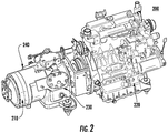
- FIG. 2 is a perspective drawing of an integrated transport refrigeration unit 200 with a compressor 230 disposed between the engine 220 and the immersed generator 210. Accordingly, generator 210 is outboard of compressor 230. As with the transport refrigeration unit of FIG. 1 , generator 210 and compressor 230 are directly coupled to the output of engine 220. Housing 240 surrounds compressor 230 and immersed generator 210 and seals a volume of refrigerant within housing 240. Refrigerant is reserved within housing 240 for uptake and re-compression by compressor 230, and both compressor 230 and generator 210 are immersed in low-pressure refrigerant that has been returned to housing 240. Thus, compressor 230 and generator 210 are cooled by the refrigerant.
- housing 240 is sealed to retain refrigerant, and generator 210 is constructed for immersion in refrigerant.
- the incorporation of the generator within the housing enables the transport refrigeration unit to be made more compact as space is no longer required to position a generator on an auxiliary shaft.
- the generator can be made relatively smaller due to decreased need to entrain air to cool the generator.
- FIG. 3 is a schematic diagram showing an integrated transport refrigeration unit 300 according to the present invention.
- engine 320 drives integrated compressor/generator unit 310 with a single shaft 330.
- Integrated compressor/generator unit 310 is sealed within a single housing (not shown in FIG. 3 ) that also serves as a low pressure reservoir for refrigerant that is returned to the compressor after the refrigerant has flowed through a typical refrigeration cycle such as having passed through a condenser and an evaporator for extracting heat from a cooled space.
- shaft 330 also drives an auxiliary generator 340 using belt 350 or other means for extracting power from shaft 330.
- auxiliary generator 340 is disposed externally from the single housing that serves as a low pressure reservoir for refrigerant returned to the compressor.
- auxiliary generator 340 is an alternator coupled with a rectifier (i.e., a DC alternator) so as to produce DC current for charging unit battery 360 and current may also be made directly available to control box 370.
- Control box 370 may draw electrical current directly from battery 360 when engine 320 is not operating or may draw power from auxiliary generator 340 when engine 320 is operating.
- Control box 370 includes an inverter (not shown) for converting DC current to alternating current at a voltage suitable for operating at least one fan 380, which provides ventilation, circulation, heat transfer for a transportable container.
- control box 370 may receive indications from the transportable container to determine whether and how to operate fan 380 and/or compressor 310. When it is desirable to operate fan 380, control box 370 may draw power from battery 360 so long as it retains adequate charge. When a state of charge in battery 360 is insufficient to operate fan 380, control box 370 may command engine 320 to operate so as to provide power via compressor/generator 310 and to re-charge unit battery 360. Similarly, when it is desirable to provided cooling to the transportable container, control box 370 may command engine 320 to operate so as to provide cooling by pumping refrigerant through its refrigeration cycle components. While engine 320 is operating, compressor/generator 310 produces power to operate fan 380, and alternator 340 produces power to charge battery 360.
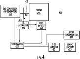
- FIG. 4 is a schematic diagram showing an exemplary integrated transport refrigeration unit 400 with a combination of direct-current and alternating-current fans.
- engine 420 drives integrated compressor/generator unit 410 with a single shaft 430.
- Integrated compressor/generator unit 410 is sealed within a single housing (not shown) that also serves as a low pressure reservoir for refrigerant that is returned to the compressor after the refrigerant has flowed through a typical refrigeration cycle such as having passed through a condenser and an evaporator for extracting heat from a cooled space.
- shaft 430 also drives auxiliary generator 440 using belt 450 or other means for extracting power from shaft 430.
- Auxiliary generator 440 may include an alternator coupled to a rectifier for producing DC current (i.e., a DC alternator) for charging unit battery 460 and current may also be made directly available to control box 470.
- Control box 470 may draw electrical current directly from battery 460 when engine 420 is not operating or may draw power from auxiliary generator 440 when engine 420 is operating.
- Control box 470 includes an inverter (not shown) for converting DC current to alternating current at a voltage suitable for operating condenser fans 480, which provide heat transfer for a transportable container.
- Control box 470 also provides power to converter 490 for providing DC current at a voltage suitable for operating evaporator fans 495, which provide heat transfer for a transportable container.
- this embodiment enables power to be delivered in various forms to drive different components. This can be useful in mobile refrigeration applications such as where it may be advantageous to employ direct current power to drive evaporator components, while it may be preferable to employ alternating current power to drive condenser components. Alternating current produced by the compressor/generator can be used to drive the condenser fan, while the auxiliary generator may be configured to provide DC power to drive the evaporator fan. Accordingly, this embodiment may be configured so as to eliminate any need for a separate rectifier device, thereby saving unit volume, weight, and cost.
- FIG. 5 is a schematic diagram showing an exemplary integrated transport refrigeration unit 500 with a combination of direct-current and alternating-current fans and an integrated high voltage battery pack.
- engine 520 drives integrated compressor/generator unit 510 with a single shaft 530.
- Integrated compressor/generator unit 510 is sealed within a single housing (not shown) that also serves as a low pressure reservoir for refrigerant that is returned to the compressor following its having flowed through a typical refrigeration cycle such as having passed through a condenser and an evaporator for extracting heat from a cooled space.
- shaft 530 also drives auxiliary generator 540 using belt 550 or other means for extracting power from shaft 530.
- Auxiliary generator 540 produces DC current for charging unit battery 560 and current may also be made directly available to control box 570.
- compressor/generator 510 produces high voltage current for use by a battery pack charger 512 to charge high voltage battery pack 514. Power stored in high voltage battery pack 514 can then be used by control box 570.
- Control box 570 may draw electrical current directly from battery 560 or from high voltage battery pack 514 when engine 520 is not operating.
- high voltage battery pack may be a commercial battery pack that generates approximately 600 volts.
- control box 570 may also draw power from auxiliary generator 540 or from compressor/generator 510, which is configured to produce high voltage current.
- Control box 570 provides power to AC/DC converter 580, which produces power or current at a sufficiently high voltage to drive high-voltage, direct-current fans 590.
- power from high voltage battery pack 514 may be used to drive compressor 510.
Landscapes
- Engineering & Computer Science (AREA)
- Mechanical Engineering (AREA)
- General Engineering & Computer Science (AREA)
- Chemical & Material Sciences (AREA)
- Combustion & Propulsion (AREA)
- Physics & Mathematics (AREA)
- Thermal Sciences (AREA)
- Devices That Are Associated With Refrigeration Equipment (AREA)
- Connection Of Motors, Electrical Generators, Mechanical Devices, And The Like (AREA)
- Control Of Charge By Means Of Generators (AREA)
Description
- In today's world, a wide variety of goods are transported via trucks, trailers and other mobile containers. Often, it is necessary to control the environment within such mobile containers. For example, it is often desirable to control the temperature and or humidity within a container. It may also be advantageous to provide for circulation the air within a container, to exchange air within a container with ambient air from outside, or to introduce other gases such as ozone, carbon dioxide, or nitrogen into a shipping container so as to maintain a desired environment within the container.
- To meet these desires, mobile containers typically make use of a transport refrigeration unit, which may be attached to a mobile container. Typically transport refrigeration units include a power source, such as a diesel engine. They also include a refrigerant loop that includes a compressor for circulating refrigerant through an evaporator and a condenser and one or more blowers for circulating air into and within the container and for facilitating exchange of heat with the refrigerant loop. A generator is often included to produce electricity to power the fans, and in some cases, a battery is also included for storing energy to enable the fans to operate when the diesel engine is not operating.
- There is a need for a transport refrigeration unit with reduced fuel consumption, reduced ownership cost, and decreased size.
- An integrated transport refrigeration unit comprises an engine providing power to drive a shaft. The shaft drives a refrigerant compressor and a generator, both of which are encased within a housing, and the generator is immersed in refrigerant. In an exemplary embodiment, an integrated transport refrigeration unit also includes an auxiliary generator driven by the shaft and disposed externally from the housing. In this embodiment, the auxiliary generator produces current for charging a battery and for operating a fan.
-
EP 1 834 818 A2 shows a transport refrigeration unit of the type configured to be mounted on the front wall of a transport trailer, comprising a compressor, a condenser heat exchanger, an evaporator heat exchanger, at least one fan assembly having at least one electric fan motor configured to provide air flow over one of the heat exchangers, and an integrally mounted unitary engine driven generator assembly configured to selectively produce at least one A.C. voltage at one or more frequencies. The generator assembly is capable of producing sufficient power to operate the compressor drive motor and the at least one fan motor. In a preferred embodiment, the generator assembly is a synchronous generator and the compressor drive motor and the at least one fan motor are configured to be directly coupled to the generator and to operate at a voltage and frequency produced by the synchronous generator. - Further embodiments of the invention are disclosed in the following, numbered paragraphs:
- 1. An integrated transport refrigeration unit comprising an engine providing power to drive a shaft, a refrigerant compressor driven by the shaft, and an integrated generator driven by the shaft, wherein both the compressor and the integrated generator are encased within a housing, and wherein the integrated generator is immersed in refrigerant.
- 2. An integrated transport refrigeration unit as described in paragraph 1, further comprising an auxiliary generator driven by the shaft and positioned externally from said housing, the auxiliary generator producing current for charging a battery and for operating a fan.
- 3. An integrated transport refrigeration unit as described in paragraph 1, wherein the integrated generator is disposed between the engine and the compressor.
- 4. An integrated transport refrigeration unit as described in paragraph 1, wherein the compressor is disposed between the engine and the integrated generator.
- 5. An integrated transport refrigeration unit as described in paragraph 1, wherein the engine is an internal combustion engine.
- 6. An integrated transport refrigeration unit as described in paragraph 1, wherein the compressor is directly coupled to the shaft.
- 7. An integrated transport refrigeration unit as described in paragraph 1, wherein the shaft is magnetically driven.
- 8. An integrated transport refrigeration unit as described in paragraph 1, further comprising a plurality of permanent magnets fixed to the shaft within the housing and windings disposed around the permanent magnets so as to generate an electrical current when the shaft rotates.
- 9. An integrated transport refrigeration unit as described in paragraph 1, further comprising an induction generator disposed on the drive shaft, wherein an alternating current is induced as a consequence of the rotation of the shaft.
- 10. An integrated transport refrigeration unit as described in paragraph 1, further comprising an auxiliary generator that is positioned externally from said housing and that is driven by a belt driven by the shaft.
- 11. An integrated transport refrigeration unit as described in paragraph 10, wherein the auxiliary generator produces current for charging a battery, wherein the battery is coupled to a control box, wherein the control box is configured to provide power to drive a fan.
- 12. An integrated transport refrigeration unit as described in paragraph 11, wherein the control box comprises an inverter for converting direct current to alternating current at a voltage suitable for operating the fan.
- 13. An integrated transport refrigeration unit as described in paragraph 11, wherein the control box is configured to receive a signal from a transportable container and to operate the fan based on the signal.
- 14. An integrated transport refrigeration unit as described in paragraph 11, wherein the control box is configured to command the engine to operate so as to cause the auxiliary generator to provide power to charge the battery.
- 15. An integrated transport refrigeration unit as described in paragraph 11, wherein the control box is configured to command the engine to operate so as to cause the compressor to provide cooling by pumping refrigerant through a set of refrigeration cycle components.
- 16. An integrated transport refrigeration unit as described in paragraph 1, wherein the integrated generator is configured to produce power to operate a fan.
- 17. An integrated transport refrigeration unit as described in paragraph 1, further comprising one or more direct-current fans and one or more alternating-current fans.
- 18. An integrated transport refrigeration unit as described in paragraph 11, wherein the control box provides power to a power converter, and wherein the power converter provides a direct current at a voltage suitable for operating an evaporator fan.
- 19. An integrated transport refrigeration unit as described in paragraph 1, wherein the integrated generator is configured to produce a high-voltage current suitable to charge a high-voltage battery pack.
- The subject matter which is regarded as the invention is particularly pointed out and distinctly claimed in the claims at the conclusion of the specification. The foregoing and other features, and advantages of the invention are apparent from the following detailed description taken in conjunction with the accompanying drawings in which:
-
FIG. 1 is a perspective drawing of an integrated transport refrigeration unit with an immersed generator disposed between the engine and the compressor; -
FIG. 2 is a perspective drawing of an integrated transport refrigeration unit with a compressor disposed between the engine and the immersed generator; -
FIG. 3 is a schematic diagram showing an exemplary integrated transport refrigeration unit with a high-voltage, alternating-current fan; -
FIG. 4 is a schematic diagram showing an exemplary integrated transport refrigeration unit with a combination of direct-current and alternating-current fans; and -
FIG. 5 is a schematic diagram showing an exemplary integrated transport refrigeration unit with a combination of direct-current and alternating-current fans and an integrated, high-voltage battery pack. - With reference to the drawings,
FIG. 1 is a perspective drawing of an integratedtransport refrigeration unit 100 with an immersedgenerator 110 disposed between anengine 120 and acompressor 130. In accordance with this embodiment,engine 120 is an internal combustion engine, such as a diesel or gasoline engine, and drives an output shaft (not shown), to which immersedgenerator 110 andcompressor 130 are directly coupled. The drive shaft may be open to the atmosphere or it may be magnetically driven.Housing 140 encases bothcompressor 130 and immersedgenerator 110 and seals a volume of refrigerant withinhousing 140.Refrigerant inlet 150 carries refrigerant tohousing 140 for uptake and re-compression bycompressor 130, andrefrigerant outlet 160 delivers re-compressed refrigerant to a high pressure coolant line for expansion in an evaporator (not shown). - Within
housing 140, bothcompressor 130 andgenerator 110 are immersed in low-pressure refrigerant that has been returned tohousing 140 viarefrigerant inlet 150. Being immersed,compressor 130 andgenerator 110 are cooled by the refrigerant. It should be noted thathousing 140 is sealed so as to retain refrigerant, andgenerator 110 is constructed using magnet wire or another wire suitable for immersion in refrigerant. In a exemplary embodiment, a single shaft is driven byengine 120, and permanent magnets are fixed to the shaft. Windings are disposed withinhousing 140 and around the permanent magnets. As the shaft is rotated by the engine, current is generated in the windings. In another exemplary embodiment, an induction generator is disposed on the drive shaft wherein an alternating current is induced as a consequence of the rotation of the shaft. In both cases,compressor 130 is also driven by the shaft, and comprises a series of pistons cycled by the rotation of the shaft. As a result of the incorporation of the generator within the housing, the transport refrigeration unit may be made more compact as space is no longer required to position a generator on an auxiliary shaft. In addition, the generator can be made smaller due to decreased need to entrain air to cool the generator. -
FIG. 2 is a perspective drawing of an integratedtransport refrigeration unit 200 with acompressor 230 disposed between theengine 220 and the immersedgenerator 210. Accordingly,generator 210 is outboard ofcompressor 230. As with the transport refrigeration unit ofFIG. 1 ,generator 210 andcompressor 230 are directly coupled to the output ofengine 220.Housing 240 surroundscompressor 230 and immersedgenerator 210 and seals a volume of refrigerant withinhousing 240. Refrigerant is reserved withinhousing 240 for uptake and re-compression bycompressor 230, and bothcompressor 230 andgenerator 210 are immersed in low-pressure refrigerant that has been returned tohousing 240. Thus,compressor 230 andgenerator 210 are cooled by the refrigerant. Also,housing 240 is sealed to retain refrigerant, andgenerator 210 is constructed for immersion in refrigerant. As with the embodiment shown inFIG. 1 , the incorporation of the generator within the housing enables the transport refrigeration unit to be made more compact as space is no longer required to position a generator on an auxiliary shaft. In addition, the generator can be made relatively smaller due to decreased need to entrain air to cool the generator. -
FIG. 3 is a schematic diagram showing an integratedtransport refrigeration unit 300 according to the present invention. In this embodiment,engine 320 drives integrated compressor/generator unit 310 with asingle shaft 330. Integrated compressor/generator unit 310 is sealed within a single housing (not shown inFIG. 3 ) that also serves as a low pressure reservoir for refrigerant that is returned to the compressor after the refrigerant has flowed through a typical refrigeration cycle such as having passed through a condenser and an evaporator for extracting heat from a cooled space. In this embodiment,shaft 330 also drives anauxiliary generator 340 usingbelt 350 or other means for extracting power fromshaft 330. Theauxiliary generator 340 is disposed externally from the single housing that serves as a low pressure reservoir for refrigerant returned to the compressor. In an exemplary embodiment,auxiliary generator 340 is an alternator coupled with a rectifier (i.e., a DC alternator) so as to produce DC current for chargingunit battery 360 and current may also be made directly available to controlbox 370.Control box 370 may draw electrical current directly frombattery 360 whenengine 320 is not operating or may draw power fromauxiliary generator 340 whenengine 320 is operating.Control box 370 includes an inverter (not shown) for converting DC current to alternating current at a voltage suitable for operating at least onefan 380, which provides ventilation, circulation, heat transfer for a transportable container. - In operation,
control box 370 may receive indications from the transportable container to determine whether and how to operatefan 380 and/orcompressor 310. When it is desirable to operatefan 380,control box 370 may draw power frombattery 360 so long as it retains adequate charge. When a state of charge inbattery 360 is insufficient to operatefan 380,control box 370 may commandengine 320 to operate so as to provide power via compressor/generator 310 and to re-chargeunit battery 360. Similarly, when it is desirable to provided cooling to the transportable container,control box 370 may commandengine 320 to operate so as to provide cooling by pumping refrigerant through its refrigeration cycle components. Whileengine 320 is operating, compressor/generator 310 produces power to operatefan 380, andalternator 340 produces power to chargebattery 360. -
FIG. 4 is a schematic diagram showing an exemplary integratedtransport refrigeration unit 400 with a combination of direct-current and alternating-current fans. In this embodiment,engine 420 drives integrated compressor/generator unit 410 with asingle shaft 430. Integrated compressor/generator unit 410 is sealed within a single housing (not shown) that also serves as a low pressure reservoir for refrigerant that is returned to the compressor after the refrigerant has flowed through a typical refrigeration cycle such as having passed through a condenser and an evaporator for extracting heat from a cooled space. In this embodiment,shaft 430 also drivesauxiliary generator 440 usingbelt 450 or other means for extracting power fromshaft 430.Auxiliary generator 440 may include an alternator coupled to a rectifier for producing DC current (i.e., a DC alternator) for chargingunit battery 460 and current may also be made directly available to controlbox 470.Control box 470 may draw electrical current directly frombattery 460 whenengine 420 is not operating or may draw power fromauxiliary generator 440 whenengine 420 is operating.Control box 470 includes an inverter (not shown) for converting DC current to alternating current at a voltage suitable for operatingcondenser fans 480, which provide heat transfer for a transportable container.Control box 470 also provides power toconverter 490 for providing DC current at a voltage suitable for operatingevaporator fans 495, which provide heat transfer for a transportable container. - Accordingly, this embodiment enables power to be delivered in various forms to drive different components. This can be useful in mobile refrigeration applications such as where it may be advantageous to employ direct current power to drive evaporator components, while it may be preferable to employ alternating current power to drive condenser components. Alternating current produced by the compressor/generator can be used to drive the condenser fan, while the auxiliary generator may be configured to provide DC power to drive the evaporator fan. Accordingly, this embodiment may be configured so as to eliminate any need for a separate rectifier device, thereby saving unit volume, weight, and cost.
-
FIG. 5 is a schematic diagram showing an exemplary integratedtransport refrigeration unit 500 with a combination of direct-current and alternating-current fans and an integrated high voltage battery pack. In this embodiment,engine 520 drives integrated compressor/generator unit 510 with asingle shaft 530. Integrated compressor/generator unit 510 is sealed within a single housing (not shown) that also serves as a low pressure reservoir for refrigerant that is returned to the compressor following its having flowed through a typical refrigeration cycle such as having passed through a condenser and an evaporator for extracting heat from a cooled space. In this embodiment,shaft 530 also drivesauxiliary generator 540 usingbelt 550 or other means for extracting power fromshaft 530.Auxiliary generator 540 produces DC current for chargingunit battery 560 and current may also be made directly available to controlbox 570. In addition, compressor/generator 510 produces high voltage current for use by abattery pack charger 512 to charge highvoltage battery pack 514. Power stored in highvoltage battery pack 514 can then be used bycontrol box 570. -
Control box 570 may draw electrical current directly frombattery 560 or from highvoltage battery pack 514 whenengine 520 is not operating. In an exemplary embodiment, high voltage battery pack may be a commercial battery pack that generates approximately 600 volts. Whenengine 520 is driving the system,control box 570 may also draw power fromauxiliary generator 540 or from compressor/generator 510, which is configured to produce high voltage current.Control box 570 provides power to AC/DC converter 580, which produces power or current at a sufficiently high voltage to drive high-voltage, direct-current fans 590. Whenengine 520 is not operating, power from highvoltage battery pack 514 may be used to drivecompressor 510. - While the invention has been described in detail in connection with only a limited number of embodiments, it should be readily understood that the invention is not limited to such disclosed embodiments. Rather, the invention can be modified to incorporate any number of variations, alterations, substitutions or equivalent arrangements not heretofore described, but which are commensurate with the spirit and scope of the invention. Additionally, while various embodiments of the invention have been described, it is to be understood that aspects of the invention may include only some of the described embodiments. Accordingly, the invention is not to be seen as limited by the foregoing description, but is only limited by the scope of the appended claims.
Claims (15)
- An integrated transport refrigeration unit (100) comprising
an engine (120) providing power to drive a shaft,
a refrigerant compressor (130) driven by the shaft, and
an integrated generator (110) driven by the shaft, wherein both the compressor (130) and the integrated generator (110) are encased within a housing (140), and
characterized in that
the integrated generator (110) is immersed in refrigerant; and
an auxiliary generator (340) is provided that is positioned externally from said housing and that is driven by a belt driven (350) by the shaft (330). - An integrated transport refrigeration unit (100) as described in claim 1, further comprising an auxiliary generator (440) driven by the shaft (430) and positioned externally from said housing, the auxiliary generator (440) producing current for charging a battery (460) and for operating a fan (495).
- An integrated transport refrigeration unit (100) as described in claim 1, wherein the integrated generator (110) is disposed between the engine (120) and the compressor (130).
- An integrated transport refrigeration unit as described in claim 1, wherein the compressor is disposed between the engine and the integrated generator.
- An integrated transport refrigeration unit (100) as described in claim 1, wherein the engine (120) is an internal combustion engine.
- An integrated transport refrigeration unit (100) as described in claim 1, wherein the compressor is directly coupled to the shaft.
- An integrated transport refrigeration unit (100) as described in claim 1, wherein the shaft is magnetically driven.
- An integrated transport refrigeration unit (100) as described in claim 1, further comprising a plurality of permanent magnets fixed to the shaft within the housing and windings disposed around the permanent magnets so as to generate an electrical current when the shaft rotates,
- An integrated transport refrigeration unit (100) as described in claim 1, further comprising an induction generator disposed on the drive shaft, wherein an alternating current is induced as a consequence of the rotation of the shaft (430).
- An integrated transport refrigeration unit (100) as described in claim 1, wherein the auxiliary generator (440) produces current for charging a battery, wherein the battery is coupled to a control box, wherein the control box is configured to provide power to drive a fan.
- An integrated transport refrigeration unit (100) as described in claim 10, wherein the control box (470) comprises an inverter for converting direct current to alternating current at a voltage suitable for operating the fan; or
wherein the control box (470) is configured to receive a signal from a transportable container and to operate the fan based on the signal or to command the engine to operate so as to cause the auxiliary generator (440) to provide power to charge the battery. - An integrated transport refrigeration unit (100) as described in claim 10, wherein the control box (470) is configured to command the engine to operate so as to cause the compressor to provide cooling by pumping refrigerant through a set of refrigeration cycle components.
- An integrated transport refrigeration unit (100) as described in claim 1, wherein the integrated generator (120) is configured to produce power to operate a fan; or
wherein the integrated generator (120) is configured to produce a high-voltage current suitable to charge a high- voltage battery pack. - An integrated transport refrigeration unit (100) as described in claim 1, further comprising one or more direct-current fans and one or more alternating-current fans.
- An integrated transport refrigeration unit (100) as described in claim 10, wherein the control box (470) provides power to a power converter, and wherein the power converter provides a direct current at a voltage suitable for operating an evaporator fan.
Applications Claiming Priority (2)
| Application Number | Priority Date | Filing Date | Title |
|---|---|---|---|
| US201161505311P | 2011-07-07 | 2011-07-07 | |
| PCT/US2012/044791 WO2013006398A2 (en) | 2011-07-07 | 2012-06-29 | Integrated transport refrigeration unit |
Publications (2)
| Publication Number | Publication Date |
|---|---|
| EP2729702A2 EP2729702A2 (en) | 2014-05-14 |
| EP2729702B1 true EP2729702B1 (en) | 2017-08-23 |
Family
ID=46465321
Family Applications (1)
| Application Number | Title | Priority Date | Filing Date |
|---|---|---|---|
| EP12732939.9A Revoked EP2729702B1 (en) | 2011-07-07 | 2012-06-29 | Integrated transport refrigeration unit |
Country Status (6)
| Country | Link |
|---|---|
| US (1) | US20140137590A1 (en) |
| EP (1) | EP2729702B1 (en) |
| CN (1) | CN103649539B (en) |
| ES (1) | ES2646185T3 (en) |
| RU (1) | RU2596677C2 (en) |
| WO (1) | WO2013006398A2 (en) |
Families Citing this family (27)
| Publication number | Priority date | Publication date | Assignee | Title |
|---|---|---|---|---|
| US20170158026A1 (en) * | 2014-07-15 | 2017-06-08 | Carrier Corporation | Transport refrigeration unit and method of driving a compressor |
| WO2016041608A1 (en) * | 2014-09-19 | 2016-03-24 | Bitzer Kuehlmaschinenbau Gmbh | Storage unit and tempering system for a storage unit |
| EP3634793B1 (en) | 2017-06-06 | 2024-03-06 | Carrier Corporation | Transport refrigeration system |
| WO2019051219A1 (en) | 2017-09-11 | 2019-03-14 | Carrier Corporation | A trailer transport refrigeration unit assisted by a tractor auxiliary power unit |
| FR3076492B1 (en) * | 2018-01-09 | 2020-01-10 | Moteurs Leroy-Somer | ASSEMBLY COMPRISING A GENERATOR AND ELECTRIC MOTORS, FOR A VEHICLE AIR CONDITIONING OR REFRIGERATION SYSTEM |
| US12270599B2 (en) | 2018-08-06 | 2025-04-08 | Carrier Corporation | Transport refrigeration unit |
| EP3626489A1 (en) | 2018-09-19 | 2020-03-25 | Thermo King Corporation | Methods and systems for energy management of a transport climate control system |
| EP3626490A1 (en) | 2018-09-19 | 2020-03-25 | Thermo King Corporation | Methods and systems for power and load management of a transport climate control system |
| US11034213B2 (en) | 2018-09-29 | 2021-06-15 | Thermo King Corporation | Methods and systems for monitoring and displaying energy use and energy cost of a transport vehicle climate control system or a fleet of transport vehicle climate control systems |
| US11059352B2 (en) | 2018-10-31 | 2021-07-13 | Thermo King Corporation | Methods and systems for augmenting a vehicle powered transport climate control system |
| US10875497B2 (en) | 2018-10-31 | 2020-12-29 | Thermo King Corporation | Drive off protection system and method for preventing drive off |
| WO2020142061A1 (en) | 2018-12-31 | 2020-07-09 | Thermo King Corporation | Methods and systems for notifying and mitigating a suboptimal event occurring in a transport climate control system |
| US12097751B2 (en) | 2018-12-31 | 2024-09-24 | Thermo King Llc | Methods and systems for providing predictive energy consumption feedback for powering a transport climate control system |
| US11993131B2 (en) | 2018-12-31 | 2024-05-28 | Thermo King Llc | Methods and systems for providing feedback for a transport climate control system |
| WO2020142066A1 (en) | 2018-12-31 | 2020-07-09 | Thermo King Corporation | Methods and systems for providing predictive energy consumption feedback for powering a transport climate control system using external data |
| US10985511B2 (en) | 2019-09-09 | 2021-04-20 | Thermo King Corporation | Optimized power cord for transferring power to a transport climate control system |
| US11135894B2 (en) | 2019-09-09 | 2021-10-05 | Thermo King Corporation | System and method for managing power and efficiently sourcing a variable voltage for a transport climate control system |
| US11458802B2 (en) | 2019-09-09 | 2022-10-04 | Thermo King Corporation | Optimized power management for a transport climate control energy source |
| US11794551B2 (en) | 2019-09-09 | 2023-10-24 | Thermo King Llc | Optimized power distribution to transport climate control systems amongst one or more electric supply equipment stations |
| US11420495B2 (en) | 2019-09-09 | 2022-08-23 | Thermo King Corporation | Interface system for connecting a vehicle and a transport climate control system |
| EP3789221B1 (en) | 2019-09-09 | 2024-06-26 | Thermo King LLC | Prioritized power delivery for facilitating transport climate control |
| US11214118B2 (en) | 2019-09-09 | 2022-01-04 | Thermo King Corporation | Demand-side power distribution management for a plurality of transport climate control systems |
| US11203262B2 (en) | 2019-09-09 | 2021-12-21 | Thermo King Corporation | Transport climate control system with an accessory power distribution unit for managing transport climate control loads |
| US11376922B2 (en) | 2019-09-09 | 2022-07-05 | Thermo King Corporation | Transport climate control system with a self-configuring matrix power converter |
| US11489431B2 (en) | 2019-12-30 | 2022-11-01 | Thermo King Corporation | Transport climate control system power architecture |
| US11852067B2 (en) * | 2022-02-28 | 2023-12-26 | Thermo King Llc | Systems and methods of using diesel particulate filter heater as a load bank |
| CN116691555A (en) * | 2022-03-01 | 2023-09-05 | 开利公司 | Transport refrigeration unit with multiple voltage source arrangements |
Citations (6)
| Publication number | Priority date | Publication date | Assignee | Title |
|---|---|---|---|---|
| US5226294A (en) | 1992-04-28 | 1993-07-13 | Thermo King Corporation | Compressor arrangement suitable for transport refrigeration systems |
| US6223546B1 (en) | 1999-04-21 | 2001-05-01 | Robert A. Chopko | Electrically powered transport refrigeration unit |
| US20030200760A1 (en) | 2002-04-26 | 2003-10-30 | Shigeki Iwanami | Composite auxiliary machine for vehicle and control unit thereof |
| US20040178636A1 (en) | 2003-03-10 | 2004-09-16 | Denso Corporation | Automotive accessories control system |
| US20050086968A1 (en) | 2003-03-04 | 2005-04-28 | Delphi Technologies, Inc. | Integrated electrical generator/starter and air conditioning compressor device and system and method for controlling same |
| WO2012138497A1 (en) | 2011-04-04 | 2012-10-11 | Carrier Corporation | Semi-electric mobile refrigerated system |
Family Cites Families (9)
| Publication number | Priority date | Publication date | Assignee | Title |
|---|---|---|---|---|
| NO129478B (en) * | 1971-01-16 | 1974-04-16 | Indel Spa | |
| DE3528519A1 (en) * | 1985-08-08 | 1987-02-19 | Kloeckner Humboldt Deutz Ag | GAS TURBINE ENGINE WITH A GENERATOR DEVICE |
| IL109967A (en) * | 1993-06-15 | 1997-07-13 | Multistack Int Ltd | Compressor |
| US5609037A (en) * | 1994-11-15 | 1997-03-11 | Fischler; Richard | Self-contained vehicle refrigeration unit |
| GB2362457A (en) * | 2000-05-16 | 2001-11-21 | Delphi Tech Inc | A cooling system for a fluid cooled generator |
| UA68837A (en) * | 2003-11-10 | 2004-08-16 | Dnipropetrovsk Academician V L | Drive of a compressor of electric train |
| US8653415B2 (en) * | 2007-04-30 | 2014-02-18 | Illinois Tool Works Inc. | Engine-driven air compressor/generator load priority control system and method |
| BRPI0721710A2 (en) * | 2007-06-07 | 2013-01-22 | Carrier Corp | Method and system for electric power supply for auxiliary electric loads |
| US8295950B1 (en) * | 2008-07-02 | 2012-10-23 | Jerry Lee Wordsworth | Intelligent power management system |
-
2012
- 2012-06-29 ES ES12732939.9T patent/ES2646185T3/en active Active
- 2012-06-29 US US14/131,001 patent/US20140137590A1/en not_active Abandoned
- 2012-06-29 CN CN201280033735.3A patent/CN103649539B/en not_active Expired - Fee Related
- 2012-06-29 EP EP12732939.9A patent/EP2729702B1/en not_active Revoked
- 2012-06-29 WO PCT/US2012/044791 patent/WO2013006398A2/en not_active Ceased
- 2012-06-29 RU RU2013157769/06A patent/RU2596677C2/en not_active IP Right Cessation
Patent Citations (6)
| Publication number | Priority date | Publication date | Assignee | Title |
|---|---|---|---|---|
| US5226294A (en) | 1992-04-28 | 1993-07-13 | Thermo King Corporation | Compressor arrangement suitable for transport refrigeration systems |
| US6223546B1 (en) | 1999-04-21 | 2001-05-01 | Robert A. Chopko | Electrically powered transport refrigeration unit |
| US20030200760A1 (en) | 2002-04-26 | 2003-10-30 | Shigeki Iwanami | Composite auxiliary machine for vehicle and control unit thereof |
| US20050086968A1 (en) | 2003-03-04 | 2005-04-28 | Delphi Technologies, Inc. | Integrated electrical generator/starter and air conditioning compressor device and system and method for controlling same |
| US20040178636A1 (en) | 2003-03-10 | 2004-09-16 | Denso Corporation | Automotive accessories control system |
| WO2012138497A1 (en) | 2011-04-04 | 2012-10-11 | Carrier Corporation | Semi-electric mobile refrigerated system |
Also Published As
| Publication number | Publication date |
|---|---|
| RU2013157769A (en) | 2015-08-20 |
| WO2013006398A2 (en) | 2013-01-10 |
| RU2596677C2 (en) | 2016-09-10 |
| CN103649539A (en) | 2014-03-19 |
| ES2646185T3 (en) | 2017-12-12 |
| US20140137590A1 (en) | 2014-05-22 |
| EP2729702A2 (en) | 2014-05-14 |
| WO2013006398A3 (en) | 2013-06-27 |
| CN103649539B (en) | 2016-10-12 |
Similar Documents
| Publication | Publication Date | Title |
|---|---|---|
| US20140137590A1 (en) | Integrated Transport Refrigeration Unit | |
| CN103476613B (en) | Semi-electric mobile refrigeration system | |
| US9975403B2 (en) | Transport refrigeration system and method for operating | |
| US20200223291A1 (en) | Transport refrigeration unit with a renewable wind-energy source | |
| US10563897B2 (en) | Transport refrigeration unit with a renewable energy source and method of operation | |
| EP3271198B1 (en) | All electric architecture truck unit | |
| US20200189361A1 (en) | Hybrid-power transport refrigeration systems | |
| US20150292784A1 (en) | Organic rankine cycle augmented power supply system for mobile refrigeration units | |
| CN104684758A (en) | Systems and methods for powering a transport refrigeration system | |
| CN105874291B (en) | Refrigeration systems for refrigerated vehicles | |
| US20210249182A1 (en) | Cooled transformer for an energy storage device | |
| EP3865700B1 (en) | Aspiration device for a natural gas engine | |
| EP3901542A1 (en) | Voltage conversion system for transport refrigeration system | |
| EP4124482A1 (en) | System and method for power control of transport refrigeration systems |
Legal Events
| Date | Code | Title | Description |
|---|---|---|---|
| PUAI | Public reference made under article 153(3) epc to a published international application that has entered the european phase |
Free format text: ORIGINAL CODE: 0009012 |
|
| 17P | Request for examination filed |
Effective date: 20140204 |
|
| AK | Designated contracting states |
Kind code of ref document: A2 Designated state(s): AL AT BE BG CH CY CZ DE DK EE ES FI FR GB GR HR HU IE IS IT LI LT LU LV MC MK MT NL NO PL PT RO RS SE SI SK SM TR |
|
| DAX | Request for extension of the european patent (deleted) | ||
| GRAP | Despatch of communication of intention to grant a patent |
Free format text: ORIGINAL CODE: EPIDOSNIGR1 |
|
| STAA | Information on the status of an ep patent application or granted ep patent |
Free format text: STATUS: GRANT OF PATENT IS INTENDED |
|
| INTG | Intention to grant announced |
Effective date: 20170317 |
|
| GRAS | Grant fee paid |
Free format text: ORIGINAL CODE: EPIDOSNIGR3 |
|
| GRAA | (expected) grant |
Free format text: ORIGINAL CODE: 0009210 |
|
| STAA | Information on the status of an ep patent application or granted ep patent |
Free format text: STATUS: THE PATENT HAS BEEN GRANTED |
|
| AK | Designated contracting states |
Kind code of ref document: B1 Designated state(s): AL AT BE BG CH CY CZ DE DK EE ES FI FR GB GR HR HU IE IS IT LI LT LU LV MC MK MT NL NO PL PT RO RS SE SI SK SM TR |
|
| REG | Reference to a national code |
Ref country code: GB Ref legal event code: FG4D |
|
| REG | Reference to a national code |
Ref country code: CH Ref legal event code: EP |
|
| REG | Reference to a national code |
Ref country code: AT Ref legal event code: REF Ref document number: 921644 Country of ref document: AT Kind code of ref document: T Effective date: 20170915 |
|
| REG | Reference to a national code |
Ref country code: IE Ref legal event code: FG4D |
|
| REG | Reference to a national code |
Ref country code: DE Ref legal event code: R096 Ref document number: 602012036302 Country of ref document: DE |
|
| REG | Reference to a national code |
Ref country code: ES Ref legal event code: FG2A Ref document number: 2646185 Country of ref document: ES Kind code of ref document: T3 Effective date: 20171212 |
|
| REG | Reference to a national code |
Ref country code: NL Ref legal event code: MP Effective date: 20170823 |
|
| REG | Reference to a national code |
Ref country code: LT Ref legal event code: MG4D |
|
| REG | Reference to a national code |
Ref country code: AT Ref legal event code: MK05 Ref document number: 921644 Country of ref document: AT Kind code of ref document: T Effective date: 20170823 |
|
| PG25 | Lapsed in a contracting state [announced via postgrant information from national office to epo] |
Ref country code: HR Free format text: LAPSE BECAUSE OF FAILURE TO SUBMIT A TRANSLATION OF THE DESCRIPTION OR TO PAY THE FEE WITHIN THE PRESCRIBED TIME-LIMIT Effective date: 20170823 Ref country code: SE Free format text: LAPSE BECAUSE OF FAILURE TO SUBMIT A TRANSLATION OF THE DESCRIPTION OR TO PAY THE FEE WITHIN THE PRESCRIBED TIME-LIMIT Effective date: 20170823 Ref country code: AT Free format text: LAPSE BECAUSE OF FAILURE TO SUBMIT A TRANSLATION OF THE DESCRIPTION OR TO PAY THE FEE WITHIN THE PRESCRIBED TIME-LIMIT Effective date: 20170823 Ref country code: NL Free format text: LAPSE BECAUSE OF FAILURE TO SUBMIT A TRANSLATION OF THE DESCRIPTION OR TO PAY THE FEE WITHIN THE PRESCRIBED TIME-LIMIT Effective date: 20170823 Ref country code: LT Free format text: LAPSE BECAUSE OF FAILURE TO SUBMIT A TRANSLATION OF THE DESCRIPTION OR TO PAY THE FEE WITHIN THE PRESCRIBED TIME-LIMIT Effective date: 20170823 Ref country code: NO Free format text: LAPSE BECAUSE OF FAILURE TO SUBMIT A TRANSLATION OF THE DESCRIPTION OR TO PAY THE FEE WITHIN THE PRESCRIBED TIME-LIMIT Effective date: 20171123 Ref country code: FI Free format text: LAPSE BECAUSE OF FAILURE TO SUBMIT A TRANSLATION OF THE DESCRIPTION OR TO PAY THE FEE WITHIN THE PRESCRIBED TIME-LIMIT Effective date: 20170823 |
|
| PG25 | Lapsed in a contracting state [announced via postgrant information from national office to epo] |
Ref country code: RS Free format text: LAPSE BECAUSE OF FAILURE TO SUBMIT A TRANSLATION OF THE DESCRIPTION OR TO PAY THE FEE WITHIN THE PRESCRIBED TIME-LIMIT Effective date: 20170823 Ref country code: BG Free format text: LAPSE BECAUSE OF FAILURE TO SUBMIT A TRANSLATION OF THE DESCRIPTION OR TO PAY THE FEE WITHIN THE PRESCRIBED TIME-LIMIT Effective date: 20171123 Ref country code: LV Free format text: LAPSE BECAUSE OF FAILURE TO SUBMIT A TRANSLATION OF THE DESCRIPTION OR TO PAY THE FEE WITHIN THE PRESCRIBED TIME-LIMIT Effective date: 20170823 Ref country code: GR Free format text: LAPSE BECAUSE OF FAILURE TO SUBMIT A TRANSLATION OF THE DESCRIPTION OR TO PAY THE FEE WITHIN THE PRESCRIBED TIME-LIMIT Effective date: 20171124 Ref country code: PL Free format text: LAPSE BECAUSE OF FAILURE TO SUBMIT A TRANSLATION OF THE DESCRIPTION OR TO PAY THE FEE WITHIN THE PRESCRIBED TIME-LIMIT Effective date: 20170823 Ref country code: IS Free format text: LAPSE BECAUSE OF FAILURE TO SUBMIT A TRANSLATION OF THE DESCRIPTION OR TO PAY THE FEE WITHIN THE PRESCRIBED TIME-LIMIT Effective date: 20171223 |
|
| PG25 | Lapsed in a contracting state [announced via postgrant information from national office to epo] |
Ref country code: CZ Free format text: LAPSE BECAUSE OF FAILURE TO SUBMIT A TRANSLATION OF THE DESCRIPTION OR TO PAY THE FEE WITHIN THE PRESCRIBED TIME-LIMIT Effective date: 20170823 Ref country code: DK Free format text: LAPSE BECAUSE OF FAILURE TO SUBMIT A TRANSLATION OF THE DESCRIPTION OR TO PAY THE FEE WITHIN THE PRESCRIBED TIME-LIMIT Effective date: 20170823 Ref country code: RO Free format text: LAPSE BECAUSE OF FAILURE TO SUBMIT A TRANSLATION OF THE DESCRIPTION OR TO PAY THE FEE WITHIN THE PRESCRIBED TIME-LIMIT Effective date: 20170823 |
|
| REG | Reference to a national code |
Ref country code: DE Ref legal event code: R026 Ref document number: 602012036302 Country of ref document: DE |
|
| PLBI | Opposition filed |
Free format text: ORIGINAL CODE: 0009260 |
|
| PG25 | Lapsed in a contracting state [announced via postgrant information from national office to epo] |
Ref country code: SM Free format text: LAPSE BECAUSE OF FAILURE TO SUBMIT A TRANSLATION OF THE DESCRIPTION OR TO PAY THE FEE WITHIN THE PRESCRIBED TIME-LIMIT Effective date: 20170823 Ref country code: EE Free format text: LAPSE BECAUSE OF FAILURE TO SUBMIT A TRANSLATION OF THE DESCRIPTION OR TO PAY THE FEE WITHIN THE PRESCRIBED TIME-LIMIT Effective date: 20170823 Ref country code: SK Free format text: LAPSE BECAUSE OF FAILURE TO SUBMIT A TRANSLATION OF THE DESCRIPTION OR TO PAY THE FEE WITHIN THE PRESCRIBED TIME-LIMIT Effective date: 20170823 |
|
| PLAX | Notice of opposition and request to file observation + time limit sent |
Free format text: ORIGINAL CODE: EPIDOSNOBS2 |
|
| REG | Reference to a national code |
Ref country code: FR Ref legal event code: PLFP Year of fee payment: 7 |
|
| 26 | Opposition filed |
Opponent name: BITZER KUEHLMASCHINENBAU GMBH Effective date: 20180517 |
|
| PGFP | Annual fee paid to national office [announced via postgrant information from national office to epo] |
Ref country code: DE Payment date: 20180522 Year of fee payment: 7 |
|
| PG25 | Lapsed in a contracting state [announced via postgrant information from national office to epo] |
Ref country code: SI Free format text: LAPSE BECAUSE OF FAILURE TO SUBMIT A TRANSLATION OF THE DESCRIPTION OR TO PAY THE FEE WITHIN THE PRESCRIBED TIME-LIMIT Effective date: 20170823 |
|
| PGFP | Annual fee paid to national office [announced via postgrant information from national office to epo] |
Ref country code: IT Payment date: 20180523 Year of fee payment: 7 Ref country code: FR Payment date: 20180605 Year of fee payment: 7 |
|
| PGFP | Annual fee paid to national office [announced via postgrant information from national office to epo] |
Ref country code: ES Payment date: 20180702 Year of fee payment: 7 Ref country code: GB Payment date: 20180522 Year of fee payment: 7 |
|
| PLBB | Reply of patent proprietor to notice(s) of opposition received |
Free format text: ORIGINAL CODE: EPIDOSNOBS3 |
|
| REG | Reference to a national code |
Ref country code: CH Ref legal event code: PL |
|
| REG | Reference to a national code |
Ref country code: BE Ref legal event code: MM Effective date: 20180630 |
|
| PG25 | Lapsed in a contracting state [announced via postgrant information from national office to epo] |
Ref country code: LU Free format text: LAPSE BECAUSE OF NON-PAYMENT OF DUE FEES Effective date: 20180629 Ref country code: MC Free format text: LAPSE BECAUSE OF FAILURE TO SUBMIT A TRANSLATION OF THE DESCRIPTION OR TO PAY THE FEE WITHIN THE PRESCRIBED TIME-LIMIT Effective date: 20170823 |
|
| REG | Reference to a national code |
Ref country code: IE Ref legal event code: MM4A |
|
| PG25 | Lapsed in a contracting state [announced via postgrant information from national office to epo] |
Ref country code: CH Free format text: LAPSE BECAUSE OF NON-PAYMENT OF DUE FEES Effective date: 20180630 Ref country code: LI Free format text: LAPSE BECAUSE OF NON-PAYMENT OF DUE FEES Effective date: 20180630 Ref country code: IE Free format text: LAPSE BECAUSE OF NON-PAYMENT OF DUE FEES Effective date: 20180629 |
|
| RDAF | Communication despatched that patent is revoked |
Free format text: ORIGINAL CODE: EPIDOSNREV1 |
|
| REG | Reference to a national code |
Ref country code: DE Ref legal event code: R064 Ref document number: 602012036302 Country of ref document: DE Ref country code: DE Ref legal event code: R103 Ref document number: 602012036302 Country of ref document: DE |
|
| PG25 | Lapsed in a contracting state [announced via postgrant information from national office to epo] |
Ref country code: BE Free format text: LAPSE BECAUSE OF NON-PAYMENT OF DUE FEES Effective date: 20180630 |
|
| RDAG | Patent revoked |
Free format text: ORIGINAL CODE: 0009271 |
|
| STAA | Information on the status of an ep patent application or granted ep patent |
Free format text: STATUS: PATENT REVOKED |
|
| 27W | Patent revoked |
Effective date: 20190530 |
|
| GBPR | Gb: patent revoked under art. 102 of the ep convention designating the uk as contracting state |
Effective date: 20190530 |
|
| PG25 | Lapsed in a contracting state [announced via postgrant information from national office to epo] |
Ref country code: CY Free format text: LAPSE BECAUSE OF FAILURE TO SUBMIT A TRANSLATION OF THE DESCRIPTION OR TO PAY THE FEE WITHIN THE PRESCRIBED TIME-LIMIT Effective date: 20170823 Ref country code: PT Free format text: LAPSE BECAUSE OF FAILURE TO SUBMIT A TRANSLATION OF THE DESCRIPTION OR TO PAY THE FEE WITHIN THE PRESCRIBED TIME-LIMIT Effective date: 20170823 |
|
| PG25 | Lapsed in a contracting state [announced via postgrant information from national office to epo] |
Ref country code: MK Free format text: LAPSE BECAUSE OF NON-PAYMENT OF DUE FEES Effective date: 20170823 |
|
| PG25 | Lapsed in a contracting state [announced via postgrant information from national office to epo] |
Ref country code: AL Free format text: LAPSE BECAUSE OF FAILURE TO SUBMIT A TRANSLATION OF THE DESCRIPTION OR TO PAY THE FEE WITHIN THE PRESCRIBED TIME-LIMIT Effective date: 20170823 |
|
| PG25 | Lapsed in a contracting state [announced via postgrant information from national office to epo] |
Ref country code: TR Free format text: LAPSE BECAUSE OF FAILURE TO SUBMIT A TRANSLATION OF THE DESCRIPTION OR TO PAY THE FEE WITHIN THE PRESCRIBED TIME-LIMIT Effective date: 20170823 |