EP2729399B1 - Endless cable winch - Google Patents
Endless cable winch Download PDFInfo
- Publication number
- EP2729399B1 EP2729399B1 EP12737234.0A EP12737234A EP2729399B1 EP 2729399 B1 EP2729399 B1 EP 2729399B1 EP 12737234 A EP12737234 A EP 12737234A EP 2729399 B1 EP2729399 B1 EP 2729399B1
- Authority
- EP
- European Patent Office
- Prior art keywords
- cable
- safety
- ratchet wheel
- endless
- pawl
- Prior art date
- Legal status (The legal status is an assumption and is not a legal conclusion. Google has not performed a legal analysis and makes no representation as to the accuracy of the status listed.)
- Active
Links
Images

Classifications
-
- B—PERFORMING OPERATIONS; TRANSPORTING
- B66—HOISTING; LIFTING; HAULING
- B66B—ELEVATORS; ESCALATORS OR MOVING WALKWAYS
- B66B5/00—Applications of checking, fault-correcting, or safety devices in elevators
- B66B5/02—Applications of checking, fault-correcting, or safety devices in elevators responsive to abnormal operating conditions
- B66B5/04—Applications of checking, fault-correcting, or safety devices in elevators responsive to abnormal operating conditions for detecting excessive speed
-
- B—PERFORMING OPERATIONS; TRANSPORTING
- B66—HOISTING; LIFTING; HAULING
- B66B—ELEVATORS; ESCALATORS OR MOVING WALKWAYS
- B66B11/00—Main component parts of lifts in, or associated with, buildings or other structures
- B66B11/04—Driving gear ; Details thereof, e.g. seals
- B66B11/043—Driving gear ; Details thereof, e.g. seals actuated by rotating motor; Details, e.g. ventilation
-
- B—PERFORMING OPERATIONS; TRANSPORTING
- B66—HOISTING; LIFTING; HAULING
- B66D—CAPSTANS; WINCHES; TACKLES, e.g. PULLEY BLOCKS; HOISTS
- B66D1/00—Rope, cable, or chain winding mechanisms; Capstans
- B66D1/02—Driving gear
- B66D1/14—Power transmissions between power sources and drums or barrels
- B66D1/20—Chain, belt, or friction drives, e.g. incorporating sheaves of fixed or variable ratio
Definitions
- the invention relates to an endless cable winch, in particular for a service lift, in particular for wind power plants, comprising a working cable and a safety cable, a driving cable pulley around at least a part of which the working cable is wrapped, a drive for driving the driving cable pulley, and further comprising a safety device for the safety cable, wherein the safety device comprises a non-driven cable pulley, which is rotatably mounted in a housing and around at least a part of which the safety cable is wrapped, and further comprising an arresting device which is coupled via a brake to the cable pulley and which blocks and breaks the safety cable by means of the brake at a predetermined speed of the safety cable at least in one direction, wherein the arresting device comprises a ratched wheel which interacts with a pawl mounted on the housing in such a way that the pawl ledges into the ratched wheel a the predetermined speed of the safety cable.
- the arresting device blocks, and brakes the safety cable by means of the brake, when the predetermined speed is reached, has the result, during the catching of the safety cable by means of the safety device, of considerably slower braking of the safety cable as compared with the blocking arresting device used in the prior art, which acts directly on the safety cable.
- braking accelerations of the order of magnitude of approximately 3 to 5 g arise during the direct catching of the safety cable by means of an arresting device
- it is possible depending on the design of the brake device to realize a considerably lower braking acceleration, for example of the order of magnitude of approximately 2 g.
- This firstly has the result that the loading of the safety cable upon the response of the safety device is considerably reduced.
- the physical and psychological stress on the personnel located in the person lifting device which is moved by means of the endless cable winch is reduced in this way. Since the brake is configured as a friction brake, there is a smooth braking operation which is still effective.
- the arresting device comprises a ratchet wheel which interacts with a pawl mounted on the housing, in such a way that the pawl latches into the ratchet wheel at a predetermined speed of the safety cable.
- an arresting device is provided which is highly robust and which is of simple and reliable design.
- the pawl has a first pawl arm and a second pawl arm, between which the pawl is pivotably mounted on the housing, wherein the pawl is preloaded against the ratchet wheel in such a way that the first pawl arm can move along the ratchet wheel up to a predetermined speed, and latches with its second pawl arm into the ratchet wheel if the predetermined speed is exceeded in the downward direction of the safety cable.
- the predetermined speed at which the blocking takes place can be finely adjusted by means of the preload of the pawl.
- a sensor for detecting a blocking of the arresting device, which sensor outputs a signal which indicates a blocking of the arresting device.
- the signal can be utilized, in the event of blocking of the arresting device, for example to shut off the drive and if appropriate implement further measures such as for example the transmission of a fault signal to a remote monitoring unit.
- means for targetedly activating the arresting device may be provided, in particular a button for moving the pawl into a latching position for latching into the ratchet wheel.
- the arresting device can be targetedly activated manually, mechanically, electrically or in some other way, for example in order, if a critical situation is detected, to activate the arresting device in order to generate a braking action.
- the arrangement may be such that the arresting device, after an activation, is automatically released again during a subsequent movement of the safety cable in the upward direction.
- the brake is in the form of a conical brake.
- the design of the brake as a conical brake yields a particularly effective braking action with a relatively small installation size.
- the friction brake comprises a first friction partner composed of a bronze alloy and a second friction partner composed of a steel alloy.
- the brake preferably has a cone angle of approximately 4° to 10°.
- a particularly expedient configuration of the brake can be attained in this way.
- a friction lining may be provided on at least one of the friction partners. It is then generally the case here that a larger cone angle is also used, of the order of magnitude of approximately 10° to 40°.
- the ratchet wheel has an external cone which is spring-loaded against an internal cone of the cable pulley.
- At least the working cable or the safety cable are wrapped around the driving cable pulley or the cable pulley with a wrap angle of less than 300°, preferably of approximately 260° to 280°, particularly preferably of approximately 270°.
- wrap angle is normally 360°
- a smaller wrap angle may also be adequate.
- a smaller wrap angle of in particular approximately 270° it is possible to dispense with a diverting roller if, in the case of the endless cable winch being used with a person lifting device, the cable should not be guided through the service lift itself but rather should be diverted laterally past the service lift and downwards by means of diverting rollers.
- the predetermined speed for the braking of the safety cable is 20 to 40 meters/minute, preferably 25 to 35 meters/minute, preferably approximately 30 meters/minute.
- the driving cable pulley and the cable pulley are mounted in a common housing.
- both the winch and also the safety device are of compact construction in a common housing.
- the safety device prefferably be formed as a separate unit with the arresting device and the brake.
- the cable pulley has a biasing device for biasing the safety cable against the cable pulley.
- the driving cable pulley has a biasing device for biasing the working cable against the driving cable pulley.
- the biasing device may be for example a spring-loaded pressing roller.
- the ratchet wheel may be mounted on a journal of the cable pulley.
- the invention also provides a person lifting device, in particular a service lift, in particular for wind power plants, which has an endless cable winch of the type described above.
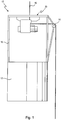
- Fig. 1 shows, in a side view and in a simplified illustration, a person lifting device in the form of a service lift for wind power plants.
- the person lifting device denoted as a whole by 10 has a lift cage 12 with a frame 18, to the top end of which is fastened an endless cable winch 20.
- the lift cage 12 hangs on a working cable which is guided through the endless cable winch 20 and which, laterally, is diverted downwards by means of a roller 14.
- Parallel to the working cable there runs a safety cable 16 which is likewise guided through the endless cable winch 20 and is guided laterally out of the endless cable winch 20 at an angle of 90° or 270° relative to the upper strand of the safety cable 16 and guided downwards by means of the diverting roller 14.
- Fig. 1 it is possible to see only the course of the safety cable 16, because the working cable runs exactly parallel thereto and is thus hidden by the safety cable 16.
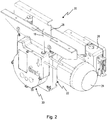
- Fig. 2 shows a perspective view of the endless cable winch 20.
- the endless cable winch 20 moves the working part 28 upwards or downwards such that the lift cage 12 moves upwards or downwards on the working cable 28.
- the winch 22 comprises a drive 24 with a motor and a gearbox, and also comprises a controller 26.
- the endless cable winch 20 comprises a winch 22 which moves the working part 28, and also a safety device 30 through which the safety cable 16 is guided.
- Fig. 3 shows the endless cable winch 20 in a front view
- Fig. 4 shows the endless cable winch 20 in a slightly enlarged front view after the housing cover of the safety device 30 has been removed.
- Fig. 4 shows the construction of an arresting device 31 which is part of the safety device 30.
- the arresting device 31 comprises a ratchet wheel 32 which interacts with a pawl 34 which is held so as to be pivotable about a pivot axis 36.
- the pawl 34 has a first pawl arm 38 and a second pawl arm 40 which protrude in opposite directions from the pivot axis 36.
- the pawl 34 is preloaded by a spring 46 in such a way that the first pawl arm 38 normally bears against the internal toothing of the ratchet wheel 32. In this position, the ratchet wheel can be moved both clockwise and also anticlockwise without the pawl leading to blocking against the ratchet wheel 32.
- the ratchet wheel 32 moves anticlockwise as per the illustration in Fig. 4 , the lift cage 12 moves downwards.
- the pawl 34 runs with its first pawl arm 38 on the toothed inner surface of the ratchet wheel 32.
- the stress of the spring 46 is now set such that, when the downward speed of the safety cable 16 reaches approximately 30 meters per minute, the interaction of the first pawl arm 38 with the toothed inner surface of the ratchet wheel 32 causes the pawl 34 to lift from the inner surface of the ratchet wheel 32 and turn over, such that the pawl latches with a latching lug 42 at the end of the second pawl arm into the inner surface of the ratchet wheel 32, and the ratchet wheel 32 is thus blocked by means of the pawl 34 mounted in the housing 54.
- the arresting device 31 is thus arrested and causes the rotatably mounted ratchet wheel 32 to be fixed at the pawl 34.
- a switch 44 is actuated.
- the switch signals to the controller 26 that the drive 24 must be shut off.
- the switch 44 may also be utilized to output for example a fault signal, which is transmitted for example to a remote monitoring device, in the event of a response.
- Fig. 4 also shows a pressing device 48 for a cable pulley over which the safety cable 16 is guided (cf. Fig. 5 ).
- the pressing device 48 has a pressing roller 50 which is pressed by means of a spring 52 against the safety cable 16 in order to press the latter into an associated guide groove of the cable pulley 68 as per Fig. 5 .
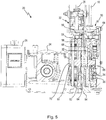
- Fig. 5 furthermore shows the construction of the winch 22.
- the winch 22 has, in a way which is basically known, a driving cable pulley 58 over which the working cable 28 is guided with a wrap angle of approximately 270°.
- the driving cable pulley 58 has a guide groove 59 in which the working cable 28 runs.
- a pressing device 56 is also provided for pressing the working cable 28 into the guide groove 59. This pressing device involves a pressing roller combined with a spring.
- the working cable 28 emerges laterally out of the winch 22, as can be seen from Fig. 2 , after a wrap angle of approximately 270°, and is then diverted downwards by means of the diverting roller 14.
- Fig. 5 also shows the drive 24 which comprises an electric motor and a gearbox.
- the output shaft 70 of the gearbox drives the driving cable pulley 58 via a shaft-type pinion (not illustrated).
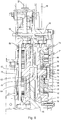
- both the driving cable pulley and also the cable pulley are mounted in the common housing 54 of the winch 22 and of the safety device 30 by means of in each case two bearings 60, 62, 64, 66.
- the safety device 30 comprises the arresting device 31 discussed above on the basis of Fig. 4 , this safety device being coupled by means of a brake, denoted as a whole by numeral 71, to the cable pulley 68 over which the safety cable 16 is guided.
- the ratchet wheel 32 has an external cone 72 which bears against an internal cone 74 of the cable pulley 68.
- the ratchet wheel 32 is preloaded against the cable pulley 68 by means of a plate spring 78 which is supported against a bearing ring 76 on a journal 73 of the cable pulley, such that there is frictional engagement between the external cone 72 of the ratchet wheel 32 and the internal cone 74 of the cable pulley 68.
- the preload of the plate spring 78 can be adjusted by means of a nut 82 which is screwed onto a thread 80 on the journal 73.
- the function of the safety device 30 is as follows:
- the non-driven cable pulley 68 runs synchronously with the driving cable pulley 58.
- the safety cable 16 thus moves at the same speed as the working cable 28 over the cable pulley 68.
- the winch 22 fails, either as a result of breakage of the working cable 28 or gearbox failure in the drive 24, which would cause the lift cage 12 to fall downwards, the lift cage 12 moves downwards initially at an increased speed until the triggering speed of the arresting device 31 is reached.
- the pawl 34 blocks against the ratchet wheel 32, such that the previously rotating cable pulley 68 is now braked by means of the conical brake 71 until the lift cage 12 finally comes to a standstill.
- the triggering speed for the arresting device 31 is approximately 30 meters per minute.
- the preload of the plate spring 78, the cone angle of the conical brake 71, which is approximately 5° to 8°, and the friction pairing of the materials of the internal cone 74 and external cone 72 (bronze alloy / steel alloy) are coordinated with one another such that, proceeding from the triggering speed of approximately 30 meters per minute, the lift cage 12 is braked with approximately 2 g. This constitutes considerably smoother braking than with conventional safety devices, by means of which the safety cable was immediately blocked, which led to catching of the lift cage 12 with approximately 5 g.
- a friction lining instead of the direct material pairing of two metals (bronze alloy / steel alloy), it would also be possible for a friction lining to be provided on at least one friction partner in order to counteract possible wear as a result of corrosion or seizing. Here, it would then generally also be necessary to use a larger cone angle of the order of magnitude of approximately 10° to 40°, for example of approximately 30°.
- the pawl 34 can also be moved into its arresting position manually, mechanically, electrically or in some other way (cf. Fig. 5 ).
- the button 45 is actuated once in order to pivot the pawl 34.
- the arresting position is automatically eliminated again if the safety cable 16 is moved in the upward direction again.
Landscapes
- Engineering & Computer Science (AREA)
- Mechanical Engineering (AREA)
- Civil Engineering (AREA)
- Structural Engineering (AREA)
- Braking Arrangements (AREA)
- Maintenance And Inspection Apparatuses For Elevators (AREA)
- Wind Motors (AREA)
- Types And Forms Of Lifts (AREA)
Description
- The invention relates to an endless cable winch, in particular for a service lift, in particular for wind power plants, comprising a working cable and a safety cable, a driving cable pulley around at least a part of which the working cable is wrapped, a drive for driving the driving cable pulley, and further comprising a safety device for the safety cable, wherein the safety device comprises a non-driven cable pulley, which is rotatably mounted in a housing and around at least a part of which the safety cable is wrapped, and further comprising an arresting device which is coupled via a brake to the cable pulley and which blocks and breaks the safety cable by means of the brake at a predetermined speed of the safety cable at least in one direction, wherein the arresting device comprises a ratched wheel which interacts with a pawl mounted on the housing in such a way that the pawl ledges into the ratched wheel a the predetermined speed of the safety cable.
- Such an endless cable winch is known from
US 3 944 185 A . - In the known endless cable winch or hoist apparatus in the event of failure of the working cable the safety cable is braked abruptly by means of a locking mechanism comprising a braking cam mounted for eccentric rotation about an axis and cooperating with a stop. This leads to a very abrupt braking resulting in a high load exerted on the safety cable, and furthermore, the persons situated in the lifting device moved by the cable winch are subjected to intense physical and psychological stress.
- It is the object of the present invention to provide an endless cable winch which provides for a safe braking in the case of failure of the working cable which is less abrupt than in prior systems.
- This object is achieved by an endless cable winch according to claim 1.
- The object of the invention is hereby fully achieved.
- Specifically, the fact that the arresting device blocks, and brakes the safety cable by means of the brake, when the predetermined speed is reached, has the result, during the catching of the safety cable by means of the safety device, of considerably slower braking of the safety cable as compared with the blocking arresting device used in the prior art, which acts directly on the safety cable. Whereas it is the case in the prior art that braking accelerations of the order of magnitude of approximately 3 to 5 g arise during the direct catching of the safety cable by means of an arresting device, it is possible depending on the design of the brake device to realize a considerably lower braking acceleration, for example of the order of magnitude of approximately 2 g. This firstly has the result that the loading of the safety cable upon the response of the safety device is considerably reduced. Secondly, the physical and psychological stress on the personnel located in the person lifting device which is moved by means of the endless cable winch is reduced in this way. Since the brake is configured as a friction brake, there is a smooth braking operation which is still effective.
- In a preferred refinement of the invention, the arresting device comprises a ratchet wheel which interacts with a pawl mounted on the housing, in such a way that the pawl latches into the ratchet wheel at a predetermined speed of the safety cable.
- In this way, an arresting device is provided which is highly robust and which is of simple and reliable design.
- Here, in a preferred refinement of the invention, the pawl has a first pawl arm and a second pawl arm, between which the pawl is pivotably mounted on the housing, wherein the pawl is preloaded against the ratchet wheel in such a way that the first pawl arm can move along the ratchet wheel up to a predetermined speed, and latches with its second pawl arm into the ratchet wheel if the predetermined speed is exceeded in the downward direction of the safety cable.
- In this way, it is possible to ensure reliable blocking of the ratchet wheel by means of the pawl. The predetermined speed at which the blocking takes place can be finely adjusted by means of the preload of the pawl.
- In a further embodiment of the invention, a sensor is provided for detecting a blocking of the arresting device, which sensor outputs a signal which indicates a blocking of the arresting device.
- In this way, the signal can be utilized, in the event of blocking of the arresting device, for example to shut off the drive and if appropriate implement further measures such as for example the transmission of a fault signal to a remote monitoring unit.
- Furthermore, means for targetedly activating the arresting device may be provided, in particular a button for moving the pawl into a latching position for latching into the ratchet wheel.
- In this way, the arresting device can be targetedly activated manually, mechanically, electrically or in some other way, for example in order, if a critical situation is detected, to activate the arresting device in order to generate a braking action.
- Here, the arrangement may be such that the arresting device, after an activation, is automatically released again during a subsequent movement of the safety cable in the upward direction.
- In a further embodiment of the invention, the brake is in the form of a conical brake.
- The design of the brake as a conical brake yields a particularly effective braking action with a relatively small installation size.
- It is furthermore preferable for the friction brake to comprise a first friction partner composed of a bronze alloy and a second friction partner composed of a steel alloy.
- It has been found that such a design of a friction brake for the application according to the invention yields particularly expedient configuration parameters which permit in particular a high braking force. It is alternatively possible for two friction partners to be used, at least one of which is provided with a friction lining.
- Here, the brake preferably has a cone angle of approximately 4° to 10°.
- A particularly expedient configuration of the brake can be attained in this way.
- It is also alternatively possible for a friction lining to be provided on at least one of the friction partners. It is then generally the case here that a larger cone angle is also used, of the order of magnitude of approximately 10° to 40°.
- This counteracts possible wear or seizing.
- In a further preferred embodiment of the invention, the ratchet wheel has an external cone which is spring-loaded against an internal cone of the cable pulley.
- These measures yield a simple and reliable construction.
- The use of a plate spring makes it possible to impart a very high pressing force, such that high braking forces can be transmitted.
- In a further embodiment of the invention, at least the working cable or the safety cable are wrapped around the driving cable pulley or the cable pulley with a wrap angle of less than 300°, preferably of approximately 260° to 280°, particularly preferably of approximately 270°.
- Whereas it is the case in conventional endless cable winches that the wrap angle is normally 360°, it has been recognized according to the invention that a smaller wrap angle may also be adequate. With a smaller wrap angle of in particular approximately 270°, it is possible to dispense with a diverting roller if, in the case of the endless cable winch being used with a person lifting device, the cable should not be guided through the service lift itself but rather should be diverted laterally past the service lift and downwards by means of diverting rollers.
- In a preferred refinement of the invention, the predetermined speed for the braking of the safety cable is 20 to 40 meters/minute, preferably 25 to 35 meters/minute, preferably approximately 30 meters/minute.
- In this way, adherence to the triggering speed predefined by the European standard EN 1808 can be ensured.
- In a further embodiment of the invention, the driving cable pulley and the cable pulley are mounted in a common housing.
- In this way, it is possible for both the winch and also the safety device to be of compact construction in a common housing.
- It would however basically also be conceivable for the safety device to be formed as a separate unit with the arresting device and the brake.
- In a further embodiment of the invention, the cable pulley has a biasing device for biasing the safety cable against the cable pulley.
- In a further embodiment of the invention, the driving cable pulley has a biasing device for biasing the working cable against the driving cable pulley.
- Here, the biasing device may be for example a spring-loaded pressing roller.
- These measures concern additional safety measures which are basically not necessary if both cables are preloaded or are loaded with a weight, but which lead to a further increase in safety.
- Furthermore, the ratchet wheel may be mounted on a journal of the cable pulley.
- Finally, a rotationally conjoint connection of the driving cable pulley and cable pulley to one another is also conceivable.
- These measures yield a more simplified construction and a compact design of the safety device and of the endless cable winch as a whole.
- The invention also provides a person lifting device, in particular a service lift, in particular for wind power plants, which has an endless cable winch of the type described above.
- It is possible here for the working cable and the safety cable to be guided laterally out of the endless cable winch at an angle of approximately 90° relative to the upper strands, and diverted downward merely by means of in each case one diverting roller.
- In this way, it is possible to attain simpler cable guidance while dispensing with further diverting rollers, and to attain a smaller structural height of the person lifting device, in particular of a hoisting cage.
- It is self-evident that the features of the invention mentioned above and the features of the invention yet to be explained below can be used not only in the respectively specified combination but rather also in other combinations or individually, without departing from the scope of the present invention.
- Further features and advantages of the invention will be apparent from the following description of preferred exemplary embodiments with reference to the drawing, in which:
- Fig. 1
- shows, in a simplified side view, a person lifting device in the form of a service lift for a wind power plant;
- Fig. 2
- shows a perspective illustration of an endless cable winch according to the invention which is used in the person lifting device as per
Fig. 1 ; - Fig. 3
- shows a front view of the endless cable winch as per
Fig. 2 ; - Fig. 4
- shows a front view of the endless cable winch as per
Fig. 3 in an enlarged illustration and after the housing cover has been removed; - Fig. 5
- shows a section through the endless cable winch as per
Fig. 2 ; and - Fig. 6
- shows, in an enlarged illustration, a partial section as per
Fig. 5 in the region of the winch and safety device. -
Fig. 1 shows, in a side view and in a simplified illustration, a person lifting device in the form of a service lift for wind power plants. - The person lifting device denoted as a whole by 10 has a
lift cage 12 with aframe 18, to the top end of which is fastened anendless cable winch 20. - The
lift cage 12 hangs on a working cable which is guided through theendless cable winch 20 and which, laterally, is diverted downwards by means of aroller 14. Parallel to the working cable there runs asafety cable 16 which is likewise guided through theendless cable winch 20 and is guided laterally out of theendless cable winch 20 at an angle of 90° or 270° relative to the upper strand of thesafety cable 16 and guided downwards by means of the divertingroller 14. InFig. 1 , it is possible to see only the course of thesafety cable 16, because the working cable runs exactly parallel thereto and is thus hidden by thesafety cable 16. - The construction and mode of operation of the
endless cable winch 20 will now be explained in more detail below on the basis ofFig.s 2 to 6 . -
Fig. 2 shows a perspective view of theendless cable winch 20. Theendless cable winch 20 moves the workingpart 28 upwards or downwards such that thelift cage 12 moves upwards or downwards on the workingcable 28. Thewinch 22 comprises adrive 24 with a motor and a gearbox, and also comprises acontroller 26. Theendless cable winch 20 comprises awinch 22 which moves the workingpart 28, and also asafety device 30 through which thesafety cable 16 is guided. -
Fig. 3 shows theendless cable winch 20 in a front view, whereasFig. 4 shows theendless cable winch 20 in a slightly enlarged front view after the housing cover of thesafety device 30 has been removed. -
Fig. 4 shows the construction of an arrestingdevice 31 which is part of thesafety device 30. The arrestingdevice 31 comprises aratchet wheel 32 which interacts with apawl 34 which is held so as to be pivotable about apivot axis 36. Thepawl 34 has afirst pawl arm 38 and asecond pawl arm 40 which protrude in opposite directions from thepivot axis 36. Thepawl 34 is preloaded by aspring 46 in such a way that thefirst pawl arm 38 normally bears against the internal toothing of theratchet wheel 32. In this position, the ratchet wheel can be moved both clockwise and also anticlockwise without the pawl leading to blocking against theratchet wheel 32. If theratchet wheel 32 moves anticlockwise as per the illustration inFig. 4 , thelift cage 12 moves downwards. Here, thepawl 34 runs with itsfirst pawl arm 38 on the toothed inner surface of theratchet wheel 32. The stress of thespring 46 is now set such that, when the downward speed of thesafety cable 16 reaches approximately 30 meters per minute, the interaction of thefirst pawl arm 38 with the toothed inner surface of theratchet wheel 32 causes thepawl 34 to lift from the inner surface of theratchet wheel 32 and turn over, such that the pawl latches with a latchinglug 42 at the end of the second pawl arm into the inner surface of theratchet wheel 32, and theratchet wheel 32 is thus blocked by means of thepawl 34 mounted in thehousing 54. The arrestingdevice 31 is thus arrested and causes the rotatably mountedratchet wheel 32 to be fixed at thepawl 34. - In the arrested state, a
switch 44 is actuated. The switch signals to thecontroller 26 that thedrive 24 must be shut off. Furthermore, theswitch 44 may also be utilized to output for example a fault signal, which is transmitted for example to a remote monitoring device, in the event of a response. -
Fig. 4 also shows apressing device 48 for a cable pulley over which thesafety cable 16 is guided (cf.Fig. 5 ). Thepressing device 48 has apressing roller 50 which is pressed by means of aspring 52 against thesafety cable 16 in order to press the latter into an associated guide groove of thecable pulley 68 as perFig. 5 . -
Fig. 5 furthermore shows the construction of thewinch 22. Thewinch 22 has, in a way which is basically known, a drivingcable pulley 58 over which the workingcable 28 is guided with a wrap angle of approximately 270°. The drivingcable pulley 58 has aguide groove 59 in which the workingcable 28 runs. Apressing device 56 is also provided for pressing the workingcable 28 into theguide groove 59. This pressing device involves a pressing roller combined with a spring. The workingcable 28 emerges laterally out of thewinch 22, as can be seen fromFig. 2 , after a wrap angle of approximately 270°, and is then diverted downwards by means of the divertingroller 14. -
Fig. 5 also shows thedrive 24 which comprises an electric motor and a gearbox. Theoutput shaft 70 of the gearbox drives the drivingcable pulley 58 via a shaft-type pinion (not illustrated). - As can be seen from the enlarged illustration of
Fig. 6 , both the driving cable pulley and also the cable pulley are mounted in thecommon housing 54 of thewinch 22 and of thesafety device 30 by means of in each case twobearings - The
safety device 30 comprises the arrestingdevice 31 discussed above on the basis ofFig. 4 , this safety device being coupled by means of a brake, denoted as a whole by numeral 71, to thecable pulley 68 over which thesafety cable 16 is guided. Theratchet wheel 32 has anexternal cone 72 which bears against aninternal cone 74 of thecable pulley 68. Theratchet wheel 32 is preloaded against thecable pulley 68 by means of aplate spring 78 which is supported against a bearingring 76 on ajournal 73 of the cable pulley, such that there is frictional engagement between theexternal cone 72 of theratchet wheel 32 and theinternal cone 74 of thecable pulley 68. The preload of theplate spring 78 can be adjusted by means of anut 82 which is screwed onto athread 80 on thejournal 73. - The function of the
safety device 30 is as follows: - In the normal situation, the
non-driven cable pulley 68 runs synchronously with the drivingcable pulley 58. Thesafety cable 16 thus moves at the same speed as the workingcable 28 over thecable pulley 68. - If, for any reason, the
winch 22 fails, either as a result of breakage of the workingcable 28 or gearbox failure in thedrive 24, which would cause thelift cage 12 to fall downwards, thelift cage 12 moves downwards initially at an increased speed until the triggering speed of the arrestingdevice 31 is reached. At approximately 30 meters per minute, thepawl 34 blocks against theratchet wheel 32, such that the previously rotatingcable pulley 68 is now braked by means of theconical brake 71 until thelift cage 12 finally comes to a standstill. - The triggering speed for the arresting
device 31 is approximately 30 meters per minute. The preload of theplate spring 78, the cone angle of theconical brake 71, which is approximately 5° to 8°, and the friction pairing of the materials of theinternal cone 74 and external cone 72 (bronze alloy / steel alloy) are coordinated with one another such that, proceeding from the triggering speed of approximately 30 meters per minute, thelift cage 12 is braked with approximately 2 g. This constitutes considerably smoother braking than with conventional safety devices, by means of which the safety cable was immediately blocked, which led to catching of thelift cage 12 with approximately 5 g. - Instead of the direct material pairing of two metals (bronze alloy / steel alloy), it would also be possible for a friction lining to be provided on at least one friction partner in order to counteract possible wear as a result of corrosion or seizing. Here, it would then generally also be necessary to use a larger cone angle of the order of magnitude of approximately 10° to 40°, for example of approximately 30°.
- By means of a
button 45, thepawl 34 can also be moved into its arresting position manually, mechanically, electrically or in some other way (cf.Fig. 5 ). For this purpose, thebutton 45 is actuated once in order to pivot thepawl 34. The arresting position is automatically eliminated again if thesafety cable 16 is moved in the upward direction again.
Claims (15)
- An endless cable winch, in particular for a service lift (10), in particular for wind power plants, comprising a working cable (28) and a safety cable (16), a driving cable pulley (58) around at least a part of which the working cable (28) is wrapped, a drive (24) for driving the driving cable pulley (58), and further comprising a safety device (30) for the safety cable (16), wherein the safety device (30) comprises a non-driven cable pulley (68), which is rotatably mounted in a housing (54) and around at least a part of which the safety cable (16) is wrapped, and further comprises an arresting device (31) which is coupled via a brake (71) to the cable pulley (68) and which blocks and brakes the safety cable (16) by means of the brake (71), at a predetermined speed of the safety cable (16) at least in one direction, wherein the arresting device (31) comprises a ratchet wheel (32) which interacts with a pawl (34) mounted on the housing (54), in such a way that the pawl (34) latches into the ratchet wheel (32) at the predetermined speed of the safety cable (16), characterized in that the ratchet wheel (32) and the cable pulley (68) are rotatable about a common axis of rotation, and in that the ratchet wheel (32) forms a friction brake (71) with the cable pulley (68).
- The endless cable winch according to claim 1, characterized in that a sensor (44) is provided for detecting a blocking of the arresting device (31), which sensor outputs a signal which indicates a blocking of the arresting device (31).
- The endless cable winch according to claim 1 or 2, characterized in that the pawl (34) has a first pawl arm (38) and a second pawl arm (40), between which the pawl (34) is pivotably mounted on the housing (54), wherein the pawl (34) is preloaded against the ratchet wheel (32) in such a way that the first pawl arm (38) can move along the ratchet wheel (32) up to the predetermined speed, and latches with its second pawl arm (40) into the ratchet wheel (32) if the predetermined speed is exceeded in the downward direction of the safety cable (16).
- The endless cable winch according to any of the preceding claims, characterized in that means (45) for targetedly activating the arresting device (31) are provided, in particular a button for moving the pawl (34) into a latching position for latching into the ratchet wheel (32).
- The endless cable winch according to one of the preceding claims, characterized in that the brake (71) is in the form of a conical brake.
- The endless cable winch according to any of claims 1 to 5, characterized in that the friction brake (71) comprises a first friction partner composed of a bronze alloy and a second friction partner composed of a steel alloy.
- The endless cable winch according to claim 6, characterized in that the brake (71) has a cone angle of approximately 4° to 10°.
- The endless cable winch according to any of claims 1 to 7, characterized in that the friction brake (71) comprises at least one friction lining.
- The endless cable winch according to any of claims 1 to 8, characterized in that the ratchet wheel (32) has an external cone (72) which is spring-loaded against an internal cone (74) of the cable pulley (68).
- The endless cable winch according to claim 9, characterized in that the ratchet wheel (32) is preloaded against the internal cone (74) of the cable pulley (68) by means of a plate spring (78), the preload of which is preferably adjustable.
- The endless cable winch according to any of the preceding claims, characterized in that at least the working cable (28) or the safety cable (16) are wrapped around the driving cable pulley (58) or the cable pulley (68) with a wrap angle of less than 300°, preferably of approximately 260 to 280°, particularly preferably of approximately 270°.
- The endless cable winch according to any of the preceding claims, characterized in that the predetermined speed for the braking of the safety cable is 20 to 40 meters/minute, preferably 25 to 35 meters/minute, preferably approximately 30 meters/minute.
- The endless cable winch according to any of the preceding claims, characterized in that the driving cable pulley (58) and the cable pulley (68) are mounted in a common housing (54).
- The endless cable winch according to any of the preceding claims, characterized in that the ratchet wheel (32) is mounted on a journal (73) of the cable pulley (68).
- A person lifting device, in particular a service lift, in particular for wind power plants, characterized by an endless cable winch (20) according to one of the preceding claims.
Priority Applications (1)
| Application Number | Priority Date | Filing Date | Title |
|---|---|---|---|
| PL12737234T PL2729399T3 (en) | 2011-07-04 | 2012-06-28 | Endless cable winch |
Applications Claiming Priority (2)
| Application Number | Priority Date | Filing Date | Title |
|---|---|---|---|
| DE102011106636A DE102011106636A1 (en) | 2011-07-04 | 2011-07-04 | Cable winch |
| PCT/EP2012/062573 WO2013004588A1 (en) | 2011-07-04 | 2012-06-28 | Endless cable winch |
Publications (2)
| Publication Number | Publication Date |
|---|---|
| EP2729399A1 EP2729399A1 (en) | 2014-05-14 |
| EP2729399B1 true EP2729399B1 (en) | 2017-06-07 |
Family
ID=46545345
Family Applications (1)
| Application Number | Title | Priority Date | Filing Date |
|---|---|---|---|
| EP12737234.0A Active EP2729399B1 (en) | 2011-07-04 | 2012-06-28 | Endless cable winch |
Country Status (12)
| Country | Link |
|---|---|
| US (1) | US9415973B2 (en) |
| EP (1) | EP2729399B1 (en) |
| JP (1) | JP6087912B2 (en) |
| CN (1) | CN103648958B (en) |
| BR (1) | BR112013032512B1 (en) |
| CA (1) | CA2839235C (en) |
| DE (1) | DE102011106636A1 (en) |
| DK (1) | DK2729399T3 (en) |
| ES (1) | ES2639471T3 (en) |
| MX (1) | MX346549B (en) |
| PL (1) | PL2729399T3 (en) |
| WO (1) | WO2013004588A1 (en) |
Families Citing this family (10)
| Publication number | Priority date | Publication date | Assignee | Title |
|---|---|---|---|---|
| CN103127627B (en) * | 2013-01-30 | 2015-07-08 | 黄柏源 | A double-brake back-and-forth controllable descending device |
| DE102013107407B4 (en) | 2013-07-12 | 2015-08-27 | Tractel Greifzug Gmbh | Wind farm with a number of wind turbines with service lift and process to maintain a wind farm |
| DE102013215901A1 (en) * | 2013-08-12 | 2015-02-12 | Duallift Gmbh | service lift |
| KR101548153B1 (en) | 2014-08-11 | 2015-08-28 | 남해이엔씨 주식회사 | Lifter for construnction works |
| DE202014010224U1 (en) | 2014-12-30 | 2016-03-31 | TÜV SÜD Industrie Service GmbH | Device for detecting at least one movement parameter of an elevator of a wind energy plant |
| WO2019081801A1 (en) * | 2017-10-27 | 2019-05-02 | Kone Corporation | Hoisting arrangement in an elevator shaft |
| DE102017129372A1 (en) | 2017-12-11 | 2019-06-13 | Wobben Properties Gmbh | Climbing aid for a wind turbine and wind turbine |
| EP3939670A1 (en) | 2020-07-13 | 2022-01-19 | Tractel Greifzug GmbH | Fall arrest device |
| CN116281706B (en) * | 2023-05-11 | 2023-08-04 | 中国海洋大学 | Ocean sounding releasing device and method |
| DE102023135942A1 (en) * | 2023-12-20 | 2025-06-26 | Michael Schramm | Rope winch and method for operating a rope winch |
Family Cites Families (24)
| Publication number | Priority date | Publication date | Assignee | Title |
|---|---|---|---|---|
| CA988476A (en) * | 1972-05-22 | 1976-05-04 | Masao Tsuda | Slow descender |
| US3944185A (en) * | 1974-06-28 | 1976-03-16 | Mayco Equipment Co., Inc. | Hoist apparatus |
| DE2623124C2 (en) * | 1976-05-22 | 1978-05-18 | A. Friedr. Flender Gmbh & Co Kg, 4290 Bocholt | Emergency lowering device for electric wire rope hoists |
| JPS6022077Y2 (en) * | 1976-10-28 | 1985-07-01 | 三菱電機株式会社 | braking device |
| DE3508035A1 (en) * | 1985-03-07 | 1986-09-18 | Thomas, Rudolf, 5200 Siegburg | HOLLOW BODY MAST WITH TRANSPORT BASKET |
| CN1029465C (en) * | 1986-01-26 | 1995-08-09 | 仲建元 | Spare steel rope hovering type anti-falling device |
| US5090666A (en) * | 1988-10-13 | 1992-02-25 | May Marvin M | Hoist apparatus |
| CA2033923C (en) * | 1991-01-10 | 1994-07-05 | Jeffrey Greaves | Safety latch for a tire carrier |
| JPH05238680A (en) * | 1992-02-25 | 1993-09-17 | Futaba Seisakusho:Kk | Motor-driven hoisting device |
| JPH08270212A (en) * | 1995-03-30 | 1996-10-15 | Nihon Bisoh Co Ltd | Tagging device of rope |
| US5810508A (en) * | 1996-07-15 | 1998-09-22 | Norfolk Fabrication, Inc. | Housing for a boat lift motor pulley and gear drive |
| US5927438A (en) * | 1996-09-30 | 1999-07-27 | Ostrobrod; Meyer | Personnel lifting-lowering system |
| DE19743458A1 (en) * | 1997-10-01 | 1998-06-25 | Johannes Rinio | Device for vertical movement of personnel lifting unit, especially on faces of high buildings |
| US5975498A (en) * | 1998-12-14 | 1999-11-02 | Deuer Manufacturing Inc. | Spare tire lift/carrier unit with dual retainers |
| US6435479B1 (en) * | 2000-07-12 | 2002-08-20 | Mag-Eh, Ltd. | Load-securing device |
| US6527252B2 (en) * | 2001-04-13 | 2003-03-04 | Edscha North America | Spare tire carrier |
| DE20217287U1 (en) * | 2002-11-09 | 2003-03-06 | System Antriebstechnik Dresden Gmbh, 01189 Dresden | Belt-driven lift machine with emergency brake is for lift cage guided on rails in shaft and suspended on support devices |
| JP4339578B2 (en) * | 2002-11-27 | 2009-10-07 | 三菱電機株式会社 | Elevator equipment |
| CN1257097C (en) * | 2003-10-14 | 2006-05-24 | 曾晓东 | Belt-drive elevator dragging machine |
| DE102004010308B4 (en) * | 2004-03-03 | 2006-07-27 | Greifzug Hebezeugbau Gmbh | Traction sheave hoist for the stage and access system hereby |
| US9592890B2 (en) * | 2004-08-06 | 2017-03-14 | Global Innovative Sports Incorporated | Towrope winch rider profile |
| DE202005019439U1 (en) * | 2005-12-09 | 2006-02-02 | Greifzug Hebezeugbau Gmbh | Lifting platform for maintenance of rotor blades of windmills with basic frame as support and rope hoist with bracing cables for movement of platform along blade length |
| CN101088897A (en) * | 2007-07-10 | 2007-12-19 | 宁波申菱电梯配件有限公司 | Novel elevator speed limiter |
| CN201842586U (en) * | 2010-11-02 | 2011-05-25 | 南昌工程学院 | Fraction hoisting device |
-
2011
- 2011-07-04 DE DE102011106636A patent/DE102011106636A1/en not_active Withdrawn
-
2012
- 2012-06-28 PL PL12737234T patent/PL2729399T3/en unknown
- 2012-06-28 EP EP12737234.0A patent/EP2729399B1/en active Active
- 2012-06-28 ES ES12737234.0T patent/ES2639471T3/en active Active
- 2012-06-28 CN CN201280033303.2A patent/CN103648958B/en active Active
- 2012-06-28 CA CA2839235A patent/CA2839235C/en active Active
- 2012-06-28 BR BR112013032512-7A patent/BR112013032512B1/en active IP Right Grant
- 2012-06-28 JP JP2014517701A patent/JP6087912B2/en active Active
- 2012-06-28 WO PCT/EP2012/062573 patent/WO2013004588A1/en not_active Ceased
- 2012-06-28 DK DK12737234.0T patent/DK2729399T3/en active
- 2012-06-28 MX MX2014000021A patent/MX346549B/en active IP Right Grant
-
2014
- 2014-01-02 US US14/146,242 patent/US9415973B2/en active Active
Also Published As
| Publication number | Publication date |
|---|---|
| JP6087912B2 (en) | 2017-03-01 |
| CA2839235A1 (en) | 2013-01-10 |
| BR112013032512A2 (en) | 2017-03-01 |
| DE102011106636A1 (en) | 2013-01-10 |
| PL2729399T3 (en) | 2017-11-30 |
| CN103648958A (en) | 2014-03-19 |
| EP2729399A1 (en) | 2014-05-14 |
| MX2014000021A (en) | 2014-07-09 |
| US9415973B2 (en) | 2016-08-16 |
| BR112013032512B1 (en) | 2021-04-20 |
| CA2839235C (en) | 2018-02-06 |
| US20140110649A1 (en) | 2014-04-24 |
| CN103648958B (en) | 2016-01-20 |
| WO2013004588A1 (en) | 2013-01-10 |
| JP2014523381A (en) | 2014-09-11 |
| DK2729399T3 (en) | 2017-07-31 |
| ES2639471T3 (en) | 2017-10-26 |
| MX346549B (en) | 2017-03-24 |
Similar Documents
| Publication | Publication Date | Title |
|---|---|---|
| CA2839235C (en) | Endless cable winch | |
| US9422140B2 (en) | Endless cable winch with overload protection | |
| US7527243B2 (en) | Platform lifting mechanism provided with a driving pulley and corresponding driving system | |
| CN102858675B (en) | Cable pull comprising an emergency braking device | |
| FI120303B (en) | Method and apparatus for triggering a captive device in an elevator | |
| US20090014253A1 (en) | Braking mechanism for moving assemblies | |
| CN105392729B (en) | Speed regulator for elevator and the lift appliance using this speed regulator for elevator | |
| JP5917764B2 (en) | Elevator equipment | |
| KR200243892Y1 (en) | Brake apparatus for elevator | |
| IT202100003905A1 (en) | Emergency brake | |
| CN217264086U (en) | Elevator brake fault monitoring device | |
| CN110316635B (en) | Manual resetting device | |
| JP2005282267A (en) | Entrance sheet opening and closing machine | |
| JP6014261B2 (en) | Elevator equipment | |
| TR201703814U (en) | LIFT SINGLE AND DOUBLE WAY SHAKE BLOCK |
Legal Events
| Date | Code | Title | Description |
|---|---|---|---|
| PUAI | Public reference made under article 153(3) epc to a published international application that has entered the european phase |
Free format text: ORIGINAL CODE: 0009012 |
|
| 17P | Request for examination filed |
Effective date: 20131213 |
|
| AK | Designated contracting states |
Kind code of ref document: A1 Designated state(s): AL AT BE BG CH CY CZ DE DK EE ES FI FR GB GR HR HU IE IS IT LI LT LU LV MC MK MT NL NO PL PT RO RS SE SI SK SM TR |
|
| DAX | Request for extension of the european patent (deleted) | ||
| GRAP | Despatch of communication of intention to grant a patent |
Free format text: ORIGINAL CODE: EPIDOSNIGR1 |
|
| STAA | Information on the status of an ep patent application or granted ep patent |
Free format text: STATUS: GRANT OF PATENT IS INTENDED |
|
| RIC1 | Information provided on ipc code assigned before grant |
Ipc: B66B 11/04 20060101ALI20161201BHEP Ipc: B66D 1/20 20060101AFI20161201BHEP Ipc: B66B 5/04 20060101ALI20161201BHEP |
|
| INTG | Intention to grant announced |
Effective date: 20161216 |
|
| GRAS | Grant fee paid |
Free format text: ORIGINAL CODE: EPIDOSNIGR3 |
|
| GRAA | (expected) grant |
Free format text: ORIGINAL CODE: 0009210 |
|
| STAA | Information on the status of an ep patent application or granted ep patent |
Free format text: STATUS: THE PATENT HAS BEEN GRANTED |
|
| AK | Designated contracting states |
Kind code of ref document: B1 Designated state(s): AL AT BE BG CH CY CZ DE DK EE ES FI FR GB GR HR HU IE IS IT LI LT LU LV MC MK MT NL NO PL PT RO RS SE SI SK SM TR |
|
| REG | Reference to a national code |
Ref country code: GB Ref legal event code: FG4D |
|
| GRAA | (expected) grant |
Free format text: ORIGINAL CODE: 0009210 |
|
| REG | Reference to a national code |
Ref country code: CH Ref legal event code: EP Ref country code: AT Ref legal event code: REF Ref document number: 899068 Country of ref document: AT Kind code of ref document: T Effective date: 20170615 |
|
| REG | Reference to a national code |
Ref country code: FR Ref legal event code: PLFP Year of fee payment: 6 |
|
| REG | Reference to a national code |
Ref country code: IE Ref legal event code: FG4D |
|
| REG | Reference to a national code |
Ref country code: DE Ref legal event code: R096 Ref document number: 602012033210 Country of ref document: DE |
|
| REG | Reference to a national code |
Ref country code: DK Ref legal event code: T3 Effective date: 20170725 |
|
| REG | Reference to a national code |
Ref country code: NL Ref legal event code: FP |
|
| REG | Reference to a national code |
Ref country code: LT Ref legal event code: MG4D |
|
| REG | Reference to a national code |
Ref country code: ES Ref legal event code: FG2A Ref document number: 2639471 Country of ref document: ES Kind code of ref document: T3 Effective date: 20171026 |
|
| PG25 | Lapsed in a contracting state [announced via postgrant information from national office to epo] |
Ref country code: FI Free format text: LAPSE BECAUSE OF FAILURE TO SUBMIT A TRANSLATION OF THE DESCRIPTION OR TO PAY THE FEE WITHIN THE PRESCRIBED TIME-LIMIT Effective date: 20170607 Ref country code: LT Free format text: LAPSE BECAUSE OF FAILURE TO SUBMIT A TRANSLATION OF THE DESCRIPTION OR TO PAY THE FEE WITHIN THE PRESCRIBED TIME-LIMIT Effective date: 20170607 Ref country code: GR Free format text: LAPSE BECAUSE OF FAILURE TO SUBMIT A TRANSLATION OF THE DESCRIPTION OR TO PAY THE FEE WITHIN THE PRESCRIBED TIME-LIMIT Effective date: 20170908 Ref country code: HR Free format text: LAPSE BECAUSE OF FAILURE TO SUBMIT A TRANSLATION OF THE DESCRIPTION OR TO PAY THE FEE WITHIN THE PRESCRIBED TIME-LIMIT Effective date: 20170607 Ref country code: NO Free format text: LAPSE BECAUSE OF FAILURE TO SUBMIT A TRANSLATION OF THE DESCRIPTION OR TO PAY THE FEE WITHIN THE PRESCRIBED TIME-LIMIT Effective date: 20170907 |
|
| REG | Reference to a national code |
Ref country code: AT Ref legal event code: MK05 Ref document number: 899068 Country of ref document: AT Kind code of ref document: T Effective date: 20170607 |
|
| PG25 | Lapsed in a contracting state [announced via postgrant information from national office to epo] |
Ref country code: LV Free format text: LAPSE BECAUSE OF FAILURE TO SUBMIT A TRANSLATION OF THE DESCRIPTION OR TO PAY THE FEE WITHIN THE PRESCRIBED TIME-LIMIT Effective date: 20170607 Ref country code: SE Free format text: LAPSE BECAUSE OF FAILURE TO SUBMIT A TRANSLATION OF THE DESCRIPTION OR TO PAY THE FEE WITHIN THE PRESCRIBED TIME-LIMIT Effective date: 20170607 Ref country code: BG Free format text: LAPSE BECAUSE OF FAILURE TO SUBMIT A TRANSLATION OF THE DESCRIPTION OR TO PAY THE FEE WITHIN THE PRESCRIBED TIME-LIMIT Effective date: 20170907 Ref country code: RS Free format text: LAPSE BECAUSE OF FAILURE TO SUBMIT A TRANSLATION OF THE DESCRIPTION OR TO PAY THE FEE WITHIN THE PRESCRIBED TIME-LIMIT Effective date: 20170607 |
|
| PG25 | Lapsed in a contracting state [announced via postgrant information from national office to epo] |
Ref country code: EE Free format text: LAPSE BECAUSE OF FAILURE TO SUBMIT A TRANSLATION OF THE DESCRIPTION OR TO PAY THE FEE WITHIN THE PRESCRIBED TIME-LIMIT Effective date: 20170607 Ref country code: AT Free format text: LAPSE BECAUSE OF FAILURE TO SUBMIT A TRANSLATION OF THE DESCRIPTION OR TO PAY THE FEE WITHIN THE PRESCRIBED TIME-LIMIT Effective date: 20170607 Ref country code: RO Free format text: LAPSE BECAUSE OF FAILURE TO SUBMIT A TRANSLATION OF THE DESCRIPTION OR TO PAY THE FEE WITHIN THE PRESCRIBED TIME-LIMIT Effective date: 20170607 Ref country code: CZ Free format text: LAPSE BECAUSE OF FAILURE TO SUBMIT A TRANSLATION OF THE DESCRIPTION OR TO PAY THE FEE WITHIN THE PRESCRIBED TIME-LIMIT Effective date: 20170607 Ref country code: SK Free format text: LAPSE BECAUSE OF FAILURE TO SUBMIT A TRANSLATION OF THE DESCRIPTION OR TO PAY THE FEE WITHIN THE PRESCRIBED TIME-LIMIT Effective date: 20170607 |
|
| REG | Reference to a national code |
Ref country code: CH Ref legal event code: PL |
|
| PG25 | Lapsed in a contracting state [announced via postgrant information from national office to epo] |
Ref country code: SM Free format text: LAPSE BECAUSE OF FAILURE TO SUBMIT A TRANSLATION OF THE DESCRIPTION OR TO PAY THE FEE WITHIN THE PRESCRIBED TIME-LIMIT Effective date: 20170607 Ref country code: IS Free format text: LAPSE BECAUSE OF FAILURE TO SUBMIT A TRANSLATION OF THE DESCRIPTION OR TO PAY THE FEE WITHIN THE PRESCRIBED TIME-LIMIT Effective date: 20171007 |
|
| REG | Reference to a national code |
Ref country code: DE Ref legal event code: R097 Ref document number: 602012033210 Country of ref document: DE |
|
| PG25 | Lapsed in a contracting state [announced via postgrant information from national office to epo] |
Ref country code: MC Free format text: LAPSE BECAUSE OF FAILURE TO SUBMIT A TRANSLATION OF THE DESCRIPTION OR TO PAY THE FEE WITHIN THE PRESCRIBED TIME-LIMIT Effective date: 20170607 |
|
| REG | Reference to a national code |
Ref country code: IE Ref legal event code: MM4A |
|
| PLBE | No opposition filed within time limit |
Free format text: ORIGINAL CODE: 0009261 |
|
| STAA | Information on the status of an ep patent application or granted ep patent |
Free format text: STATUS: NO OPPOSITION FILED WITHIN TIME LIMIT |
|
| PG25 | Lapsed in a contracting state [announced via postgrant information from national office to epo] |
Ref country code: LU Free format text: LAPSE BECAUSE OF NON-PAYMENT OF DUE FEES Effective date: 20170628 Ref country code: IE Free format text: LAPSE BECAUSE OF NON-PAYMENT OF DUE FEES Effective date: 20170628 Ref country code: LI Free format text: LAPSE BECAUSE OF NON-PAYMENT OF DUE FEES Effective date: 20170630 Ref country code: CH Free format text: LAPSE BECAUSE OF NON-PAYMENT OF DUE FEES Effective date: 20170630 |
|
| 26N | No opposition filed |
Effective date: 20180308 |
|
| PG25 | Lapsed in a contracting state [announced via postgrant information from national office to epo] |
Ref country code: SI Free format text: LAPSE BECAUSE OF FAILURE TO SUBMIT A TRANSLATION OF THE DESCRIPTION OR TO PAY THE FEE WITHIN THE PRESCRIBED TIME-LIMIT Effective date: 20170607 |
|
| REG | Reference to a national code |
Ref country code: FR Ref legal event code: PLFP Year of fee payment: 7 |
|
| PG25 | Lapsed in a contracting state [announced via postgrant information from national office to epo] |
Ref country code: MT Free format text: LAPSE BECAUSE OF NON-PAYMENT OF DUE FEES Effective date: 20170628 |
|
| PG25 | Lapsed in a contracting state [announced via postgrant information from national office to epo] |
Ref country code: HU Free format text: LAPSE BECAUSE OF FAILURE TO SUBMIT A TRANSLATION OF THE DESCRIPTION OR TO PAY THE FEE WITHIN THE PRESCRIBED TIME-LIMIT; INVALID AB INITIO Effective date: 20120628 |
|
| PG25 | Lapsed in a contracting state [announced via postgrant information from national office to epo] |
Ref country code: CY Free format text: LAPSE BECAUSE OF NON-PAYMENT OF DUE FEES Effective date: 20170607 |
|
| PG25 | Lapsed in a contracting state [announced via postgrant information from national office to epo] |
Ref country code: MK Free format text: LAPSE BECAUSE OF FAILURE TO SUBMIT A TRANSLATION OF THE DESCRIPTION OR TO PAY THE FEE WITHIN THE PRESCRIBED TIME-LIMIT Effective date: 20170607 |
|
| PG25 | Lapsed in a contracting state [announced via postgrant information from national office to epo] |
Ref country code: PT Free format text: LAPSE BECAUSE OF FAILURE TO SUBMIT A TRANSLATION OF THE DESCRIPTION OR TO PAY THE FEE WITHIN THE PRESCRIBED TIME-LIMIT Effective date: 20170607 |
|
| PG25 | Lapsed in a contracting state [announced via postgrant information from national office to epo] |
Ref country code: AL Free format text: LAPSE BECAUSE OF FAILURE TO SUBMIT A TRANSLATION OF THE DESCRIPTION OR TO PAY THE FEE WITHIN THE PRESCRIBED TIME-LIMIT Effective date: 20170607 |
|
| PGFP | Annual fee paid to national office [announced via postgrant information from national office to epo] |
Ref country code: NL Payment date: 20250821 Year of fee payment: 14 |
|
| PGFP | Annual fee paid to national office [announced via postgrant information from national office to epo] |
Ref country code: ES Payment date: 20250826 Year of fee payment: 14 |
|
| PGFP | Annual fee paid to national office [announced via postgrant information from national office to epo] |
Ref country code: DK Payment date: 20250825 Year of fee payment: 14 Ref country code: DE Payment date: 20250826 Year of fee payment: 14 |
|
| PGFP | Annual fee paid to national office [announced via postgrant information from national office to epo] |
Ref country code: TR Payment date: 20250825 Year of fee payment: 14 Ref country code: PL Payment date: 20250821 Year of fee payment: 14 Ref country code: IT Payment date: 20250825 Year of fee payment: 14 |
|
| PGFP | Annual fee paid to national office [announced via postgrant information from national office to epo] |
Ref country code: BE Payment date: 20250820 Year of fee payment: 14 Ref country code: GB Payment date: 20250820 Year of fee payment: 14 |
|
| PGFP | Annual fee paid to national office [announced via postgrant information from national office to epo] |
Ref country code: FR Payment date: 20250828 Year of fee payment: 14 |