EP2729108B2 - Motion-based power assist system for wheelchairs - Google Patents
Motion-based power assist system for wheelchairs Download PDFInfo
- Publication number
- EP2729108B2 EP2729108B2 EP12807785.6A EP12807785A EP2729108B2 EP 2729108 B2 EP2729108 B2 EP 2729108B2 EP 12807785 A EP12807785 A EP 12807785A EP 2729108 B2 EP2729108 B2 EP 2729108B2
- Authority
- EP
- European Patent Office
- Prior art keywords
- motion
- power assist
- wheelchair
- assist system
- drive
- Prior art date
- Legal status (The legal status is an assumption and is not a legal conclusion. Google has not performed a legal analysis and makes no representation as to the accuracy of the status listed.)
- Active
Links
- 230000033001 locomotion Effects 0.000 title claims description 38
- 230000001133 acceleration Effects 0.000 claims description 18
- 230000004913 activation Effects 0.000 claims description 13
- 238000005259 measurement Methods 0.000 claims description 12
- 208000027418 Wounds and injury Diseases 0.000 description 4
- 238000013459 approach Methods 0.000 description 4
- 230000008901 benefit Effects 0.000 description 4
- 230000006378 damage Effects 0.000 description 4
- 208000014674 injury Diseases 0.000 description 4
- 210000001364 upper extremity Anatomy 0.000 description 4
- 238000013461 design Methods 0.000 description 3
- 238000000034 method Methods 0.000 description 2
- 230000004044 response Effects 0.000 description 2
- 230000005355 Hall effect Effects 0.000 description 1
- 235000014676 Phragmites communis Nutrition 0.000 description 1
- 206010039227 Rotator cuff syndrome Diseases 0.000 description 1
- 230000003213 activating effect Effects 0.000 description 1
- 230000006978 adaptation Effects 0.000 description 1
- 230000005540 biological transmission Effects 0.000 description 1
- 208000003295 carpal tunnel syndrome Diseases 0.000 description 1
- 230000009194 climbing Effects 0.000 description 1
- 230000003247 decreasing effect Effects 0.000 description 1
- 230000001419 dependent effect Effects 0.000 description 1
- 238000011161 development Methods 0.000 description 1
- 230000000694 effects Effects 0.000 description 1
- 238000005516 engineering process Methods 0.000 description 1
- 230000007613 environmental effect Effects 0.000 description 1
- 230000005284 excitation Effects 0.000 description 1
- 231100001261 hazardous Toxicity 0.000 description 1
- 238000012986 modification Methods 0.000 description 1
- 230000004048 modification Effects 0.000 description 1
- 210000003205 muscle Anatomy 0.000 description 1
- 230000003287 optical effect Effects 0.000 description 1
- 230000008092 positive effect Effects 0.000 description 1
- 230000008569 process Effects 0.000 description 1
- 238000012545 processing Methods 0.000 description 1
- 238000005096 rolling process Methods 0.000 description 1
- 210000000707 wrist Anatomy 0.000 description 1
Images


Classifications
-
- A—HUMAN NECESSITIES
- A61—MEDICAL OR VETERINARY SCIENCE; HYGIENE
- A61G—TRANSPORT, PERSONAL CONVEYANCES, OR ACCOMMODATION SPECIALLY ADAPTED FOR PATIENTS OR DISABLED PERSONS; OPERATING TABLES OR CHAIRS; CHAIRS FOR DENTISTRY; FUNERAL DEVICES
- A61G5/00—Chairs or personal conveyances specially adapted for patients or disabled persons, e.g. wheelchairs
- A61G5/04—Chairs or personal conveyances specially adapted for patients or disabled persons, e.g. wheelchairs motor-driven
- A61G5/041—Chairs or personal conveyances specially adapted for patients or disabled persons, e.g. wheelchairs motor-driven having a specific drive-type
- A61G5/045—Rear wheel drive
-
- A—HUMAN NECESSITIES
- A61—MEDICAL OR VETERINARY SCIENCE; HYGIENE
- A61G—TRANSPORT, PERSONAL CONVEYANCES, OR ACCOMMODATION SPECIALLY ADAPTED FOR PATIENTS OR DISABLED PERSONS; OPERATING TABLES OR CHAIRS; CHAIRS FOR DENTISTRY; FUNERAL DEVICES
- A61G5/00—Chairs or personal conveyances specially adapted for patients or disabled persons, e.g. wheelchairs
- A61G5/04—Chairs or personal conveyances specially adapted for patients or disabled persons, e.g. wheelchairs motor-driven
- A61G5/047—Chairs or personal conveyances specially adapted for patients or disabled persons, e.g. wheelchairs motor-driven by a modular detachable drive system
-
- A—HUMAN NECESSITIES
- A61—MEDICAL OR VETERINARY SCIENCE; HYGIENE
- A61G—TRANSPORT, PERSONAL CONVEYANCES, OR ACCOMMODATION SPECIALLY ADAPTED FOR PATIENTS OR DISABLED PERSONS; OPERATING TABLES OR CHAIRS; CHAIRS FOR DENTISTRY; FUNERAL DEVICES
- A61G5/00—Chairs or personal conveyances specially adapted for patients or disabled persons, e.g. wheelchairs
- A61G5/04—Chairs or personal conveyances specially adapted for patients or disabled persons, e.g. wheelchairs motor-driven
- A61G5/048—Power-assistance activated by pushing on hand rim or on handlebar
-
- A—HUMAN NECESSITIES
- A61—MEDICAL OR VETERINARY SCIENCE; HYGIENE
- A61G—TRANSPORT, PERSONAL CONVEYANCES, OR ACCOMMODATION SPECIALLY ADAPTED FOR PATIENTS OR DISABLED PERSONS; OPERATING TABLES OR CHAIRS; CHAIRS FOR DENTISTRY; FUNERAL DEVICES
- A61G2203/00—General characteristics of devices
- A61G2203/10—General characteristics of devices characterised by specific control means, e.g. for adjustment or steering
- A61G2203/12—Remote controls
-
- A—HUMAN NECESSITIES
- A61—MEDICAL OR VETERINARY SCIENCE; HYGIENE
- A61G—TRANSPORT, PERSONAL CONVEYANCES, OR ACCOMMODATION SPECIALLY ADAPTED FOR PATIENTS OR DISABLED PERSONS; OPERATING TABLES OR CHAIRS; CHAIRS FOR DENTISTRY; FUNERAL DEVICES
- A61G2203/00—General characteristics of devices
- A61G2203/30—General characteristics of devices characterised by sensor means
- A61G2203/36—General characteristics of devices characterised by sensor means for motion
Definitions
- This invention relates to a power assist system for manual wheelchairs, specifically a system that employs motion-based sensing for recognition of user propulsion and braking.
- Wheelchair propulsion is one activity that has been associated with the development of these upper extremity injuries. It is recommended that users reduce how hard they push on the handrim and to do it less frequently in order to reduce the stresses of propulsion on the upper body.
- Prior art presents power attachment units that have been used to mount to manual wheelchairs to assist in propulsion.
- the typical power add-on comparable to that disclosed in US Patent No. 4,759,418 , employs a linkage system that mounts to the wheelchair frame and trails in between the two rear wheels.
- An electric motor powers a drive wheel that is controlled by a push button located within reach of the user.
- This type of design not common to all power attachments, also employs a steering bar that attaches to the front casters in order to guide the wheelchair when being driven by the power add-on.
- These electric drive attachments are known to be successful in helping to reduce the physical effort needed for propulsion.
- a drawback is that these types of systems completely eliminate the need for pushing because the user drives the wheelchair, rather than maneuvers it through pushes. In this situation, the user does not benefit from the physical exercise of manual propulsion or the psychological benefits of not being dependent on the device for transportation.
- Push activated power assist wheels combine the benefits of manual push operation by the user and power assistance to reduce the demand on the user's upper extremities during propulsion.
- Push activated power assist wheels similar to those disclosed in US Patent No. 5,818,189 , are battery powered wheels that employ either force and torque sensors, or both, to measure the force applied to the handrims from the user and amplify that force through the use of motors embedded in the wheels to drive the wheelchair forward or backward.
- This technology has been shown to have a number of positive effects on wheelchair users, including reduced energy expenditure, reduced push cadence, reduced muscle activation, decreased range of motion, easier hill climbing, increased propulsion speed and reduced pain during propulsion for those users already experiencing pain.
- JPH10314234 describes a wheelchair with a power assist system.
- the left and right rear wheels of the wheelchair are independently controlled so as to facilitate easy turning.
- the present invention comprises a motion-based power assist system for manual wheelchairs as claimed in claim 1.
- This power assist system uses the motion, including the angular and linear velocities and accelerations, of the power assist system in order to sense when a push is being performed on the handrims.
- the system uses different kinematic sensors, not force or torque sensors like the prior art, in order to measure when the wheelchair is accelerating past a certain minimal threshold, and recognizes that this is the result of the user performing a push.
- the system then provides an assistive force-pulse that is related to the experienced acceleration and velocity from propulsion.
- the system By using the kinematics of the power assist system, the system will be able to recognize different situations and adjust its contribution to the user's propulsion to compensate.
- the present invention can recognize situations when the user is trying to stop, slow down, or is beginning to tip, and in response cut off all driving assistance.
- the use of the power assist system motion and kinematics as the input to the push activation control is novel.
- Prior art devices tend to add significant weight to the wheelchair, making it difficult to get the wheelchair into and out of a car for even the strongest user. Battery life is also an issue because the power assist wheels are simply too heavy to push around without the power assist.
- the aforementioned motion-based push activation is employed on a single drive wheel attachment that mounts to the axle of a wheelchair midway between the rear wheels. Attachment mounts are clamped to the axle and attach to the drive wheel attachment, allowing for quick connecting and releasing of the system for easy transport.
- a merely illustrative example employs the motion-based push activation on electric hub motors that are embedded in the rear drive wheels of a wheelchair.
- the handrims on the rear drive wheels can be directly mounted to the wheel rim, as on traditional non-power assist wheelchair wheels.
- Another merely illustrative example embodiment employs the said motion-based push activation on wheelchair mounted motors that drive the rear wheels of the wheelchair.
- This illustrative example uses the same motion-based means to activate frame mounted motors, instead of the aforementioned wheel mounted motors, that in turn power the driven rear wheels for an assistive force to the wheelchair and user.
- the present invention comprises a power assist system used on a manual wheelchair.
- Motion-based instrumentation measures the kinematics of the power assist system.
- the kinematics measured include, but are not limited to, linear velocities, angular velocities, linear accelerations, and angular accelerations. These parameters are quantified using a range of instruments, including but not limited to, gyroscopes, encoders, potentiometers, inertia measuring units, and multi-axis accelerometers. From these motion-based measurements, push activation can be recognized.
- the push activation recognition employs the principle that when the user is applying a push to the rim mounted handrim of typical wheelchair rear wheels 16 on a generic manual wheelchair 8 , as shown in Figure 1 , the wheelchair rear wheels 16 are being accelerated by the user. If the rear wheels 16 are experiencing an angular acceleration then the wheelchair 8 and all onboard parts will experience acceleration. Because the wheelchair is accelerating, the power assist which is connected to it will also accelerate. If the power assist acceleration measurements are found to be above a threshold of approximately 1.5 m/s/s, a user push will be recognized. Similarly, if the power assist deceleration measurements are found to be below a threshold of approximately 1.5 m/s/s, a user brake will be recognized.
- the push recognition triggers the activation of an assistive power-pulse to help in the propulsion of the wheelchair 8 and the user that is performing the push.
- the power assist provided will be related to the manual power input as calculated from the motion-based sensors.
- the power assist drive is set to the speed reached during the user's push. When user braking is detected, the provided power is discontinued.
- FIGS 1 and 2 show an embodiment of the power assist system employing the motion-based push activation.
- the power assist system which in this embodiment comprises a single wheel power assist attachment 10 , is shown mounted on a generic wheelchair 8 , comprising a drive linkage 18 , an electric hub drive wheel 20 , a mounting attachment 22 , and a remote control device 24 .
- the single wheel power assist attachment 10 is positioned between the wheelchair drive wheels 16 such that the electric drive wheel 20 contacts the ground at a point midway between the wheelchair drive wheels 16 . This positioning prevents the wheelchair from turning or drifting when an assistive force is provided, while not significantly hindering the rotation of the chair when desired for maneuvering.
- the single wheel power assist attachment 10 and drive linkage 18 are also angled such that as the drive wheel power is increased, the wheel digs into the ground for ideal traction control.
- the electric drive wheel 20 mounts to the distal end of the drive linkage 18 , which is pivotally attached to the wheelchair axle bar 14 through the mounting attachment 22 . While Figure 1 and Figure 2 show an embodiment with a singular mount attachment 22 , in other embodiments a plurality or multitude of mounting attachments may be used to connect to the drive linkage 18.
- a remote control device 24 comprises part of the single wheel power assist attachment 10 to turn the unit on and modulate between multiple configuration settings for providing different amounts of driving force related to the sensed acceleration of the power assist system from the push of the user.
- the drive linkage 18 contains a shell or frame 30 , a battery pack 32 , custom printed circuit board 28 , and electric hub motor 20 .
- the primary role of the custom circuit board 28 is to receive sensor measurements, process those measurements to determine whether the users is pushing or braking, and then deliver the appropriate amount of power from the battery to the motor 20 .
- Motion sensors can include inertial measurement units (gyroscopes, accelerometers and magnetometers) on the custom printed circuit board 28 , rotational position sensors (optical encoders, Hall Effect sensors, or reed switches) in the drive motor 20 , or inertial measurement units on the remote control device 24 .
- Determining the linear acceleration of the wheelchair can be accomplished using several of these sensing modalities individually or with increased fidelity when done in combination to filter out any undesired motion artifacts, such as rolling over bumps or down slopes.
- the simplest method to derive linear acceleration of the wheelchair is to frequently sample the rotational position of the drive wheel 20 and differentiate discrete samples to derive the rotational speed and then differentiate rotational speed values to determine the rotational acceleration of the wheel.
- the linear acceleration of the wheelchair is directly related to the rotational acceleration of the drive wheel 20 . Accelerations that occur when the power assist components are experiencing rapid changes in attitude (uphill/downhill angle) or vertical acceleration can be ignored as artifacts of environmental factors and not related to the user pushing or braking the wheelchair.
- Sensor measurements and motor power is passed to and from the printed circuit board 28 by cables that pass though the motor axle 26 .
- Sensor measurements and configuration information from the remote control device 24 is passed to the printed circuit board 28 wirelessly using any of a number of standard data transmission protocols.
- the power assist unit 10 can be made to accommodate wheelchairs of varying rear wheel sizes by allowing the linkage pivot point to be adjusted along a slide pocket 36 in the drive linkage frame 30 , as shown in Figure 4 .
- the pivot location can then be fixed by tightening machine screws in the pivot slider 34 .
- the slide range can be limited using a stop in the slide track 38 .
- the remote control device 24 shown removed from the wheelchair in Figure 5 , can be made to slide onto the seat upholstery using a simple spring clip 40. In this embodiment, it can be quickly installed onto a wheelchair without the use of tools and it can be easily removed when the power assist is not needed.
- the remote can be used to turn the unit on using a button or switch 72 .
- Another use for the remote is to allow the user to select between various modes of operation, such as LOW 42 and HIGH 44 .
- Low and high modes can serve to decrease or increase the level of power delivered to the motor for any applied push. This can be accomplished by altering the multiplier used in setting the motor power in response to a measured acceleration. In an alternate approach, low and high modes could be used to limit the maximum drive speed of the motor for indoor and outdoor use.
- motion-based push activation is used on two wheel hub motors incorporated into each of the wheelchair drive wheels.
- the design and operation of hub motors is well-known in the prior art.
- the motor assembly comprises a self-contained unit which includes a center shaft that fixable mounts the wheelchair to a stator.
- the motor housing has permanently mounted magnets and is rotationally driven by the push and pulling forces induced by the electrical excitation of the stator.
- the rotationally driven motor housing is connected to the tire supporting rim of the wheelchair wheel.
- the nature of this power assist system allows for the handrims to be directly mounted to the rim of the wheelchair drive wheels. As the user performs a push to the handrims, the wheelchair accelerates, activating the power assist through the motion-based recognition instrumentation.
- the instrumentation and motion control processing is similar to the previously described embodiment.
- the primary difference is that the rotational position of the two rear wheels would be measured directly and averaged to yield a single rotational position, which would then be processed as previously described.
- Each rear wheel would communicate wirelessly with the other in order to exchange rotational position information.
- Each drive wheel would be set to the same drive speed setting at the same time. Similarly, power to each drive wheel would be discontinued at the same time when a braking event is detected.
- motion-based push activation is incorporated into a wheelchair frame fixed drive system.
- the wheelchair wheels are secured to the wheelchair as normally done.
- Drive motors are then affixed to the frame of the wheelchair and the output shafts are pressed into the rear wheel tires to effectively couple their rotations together.
- the motor power is mechanically transferred to the rear wheels providing propulsion assistance.
- the mechanical means of transferring rotation from the drive motor to the rear wheels includes but is not limited to friction, gears, or belts, all of which is operationally well-known and need not be explained.
Landscapes
- Health & Medical Sciences (AREA)
- Life Sciences & Earth Sciences (AREA)
- Animal Behavior & Ethology (AREA)
- General Health & Medical Sciences (AREA)
- Public Health (AREA)
- Veterinary Medicine (AREA)
- Handcart (AREA)
- Electric Propulsion And Braking For Vehicles (AREA)
Description
- This application claims benefit of and priority to
U.S. Provisional Application No. 61/504,949, filed July 6, 2011, by Mark Richter - This invention relates to a power assist system for manual wheelchairs, specifically a system that employs motion-based sensing for recognition of user propulsion and braking.
- Manual wheelchairs are the primary mode of locomotion for millions of people around the world. Upper limb pain and injury is very common among these manual wheelchair users and can severely impact mobility, independence and quality of life. The most common types of injury are impingement syndrome of the shoulder and carpal tunnel syndrome of the wrist. Upper limb pain and injury is an emotionally, physically and financially costly problem.
- Wheelchair propulsion is one activity that has been associated with the development of these upper extremity injuries. It is recommended that users reduce how hard they push on the handrim and to do it less frequently in order to reduce the stresses of propulsion on the upper body.
- Prior art presents power attachment units that have been used to mount to manual wheelchairs to assist in propulsion. The typical power add-on, comparable to that disclosed in
US Patent No. 4,759,418 , employs a linkage system that mounts to the wheelchair frame and trails in between the two rear wheels. An electric motor powers a drive wheel that is controlled by a push button located within reach of the user. This type of design, not common to all power attachments, also employs a steering bar that attaches to the front casters in order to guide the wheelchair when being driven by the power add-on. These electric drive attachments are known to be successful in helping to reduce the physical effort needed for propulsion. A drawback is that these types of systems completely eliminate the need for pushing because the user drives the wheelchair, rather than maneuvers it through pushes. In this situation, the user does not benefit from the physical exercise of manual propulsion or the psychological benefits of not being dependent on the device for transportation. - Another prior art is the push activated power assist wheels. These combine the benefits of manual push operation by the user and power assistance to reduce the demand on the user's upper extremities during propulsion. Push activated power assist wheels, similar to those disclosed in
US Patent No. 5,818,189 , are battery powered wheels that employ either force and torque sensors, or both, to measure the force applied to the handrims from the user and amplify that force through the use of motors embedded in the wheels to drive the wheelchair forward or backward. This technology has been shown to have a number of positive effects on wheelchair users, including reduced energy expenditure, reduced push cadence, reduced muscle activation, decreased range of motion, easier hill climbing, increased propulsion speed and reduced pain during propulsion for those users already experiencing pain. - The drawback with this approach is that the employment of force and torque sensors to recognize and quantify the amplitude of the push significantly complicates the design. The handrims must be mounted to the wheel hubs, instead of the wheel rim as in typical manual wheelchairs, causing a significant increase in complexity. Added cost and weight of these devices then becomes inherent when this type of approach is taken. Additionally, because measurements are focused on the handrim, hazardous situations can be escalated by the assistive power.
-
JPH10314234 - Accordingly, there is a need for power assist system that addresses the issues of the prior art and devices.
- The present invention comprises a motion-based power assist system for manual wheelchairs as claimed in claim 1. This power assist system uses the motion, including the angular and linear velocities and accelerations, of the power assist system in order to sense when a push is being performed on the handrims. The system uses different kinematic sensors, not force or torque sensors like the prior art, in order to measure when the wheelchair is accelerating past a certain minimal threshold, and recognizes that this is the result of the user performing a push. The system then provides an assistive force-pulse that is related to the experienced acceleration and velocity from propulsion.
- By using the kinematics of the power assist system, the system will be able to recognize different situations and adjust its contribution to the user's propulsion to compensate. By measuring the kinematics of the power assist system, the present invention can recognize situations when the user is trying to stop, slow down, or is beginning to tip, and in response cut off all driving assistance. The use of the power assist system motion and kinematics as the input to the push activation control is novel. Prior art devices tend to add significant weight to the wheelchair, making it difficult to get the wheelchair into and out of a car for even the strongest user. Battery life is also an issue because the power assist wheels are simply too heavy to push around without the power assist.
- In one exemplary embodiment of the invention, the aforementioned motion-based push activation is employed on a single drive wheel attachment that mounts to the axle of a wheelchair midway between the rear wheels. Attachment mounts are clamped to the axle and attach to the drive wheel attachment, allowing for quick connecting and releasing of the system for easy transport.
- A merely illustrative example employs the motion-based push activation on electric hub motors that are embedded in the rear drive wheels of a wheelchair. In using the motion of the wheelchair and its parts as the input for push activation, the handrims on the rear drive wheels can be directly mounted to the wheel rim, as on traditional non-power assist wheelchair wheels.
- Another merely illustrative example embodiment employs the said motion-based push activation on wheelchair mounted motors that drive the rear wheels of the wheelchair. This illustrative example uses the same motion-based means to activate frame mounted motors, instead of the aforementioned wheel mounted motors, that in turn power the driven rear wheels for an assistive force to the wheelchair and user.
-
-
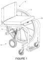
Figure 1 shows an isometric view of an exemplary embodiment in accordance with the present invention, a single drive wheel power assist attachment and remote control device mounted to a generic wheelchair. One of the rear wheels is removed for clarity. -
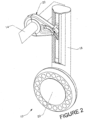
Figure 2 shows an enlarged view of the single drive wheel power assist attachment ofFigure 1 mounted to the axle bar of a wheelchair frame. -
Figure 3 shows an exploded assembly view of the single drive wheel power assist attachment ofFigure 1 removed from the wheelchair. -
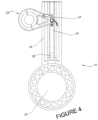
Figure 4 shows an enlarged view of the single drive wheel power assist attachment ofFigure 1 mounted to the axle bar clamp, with the wheelchair removed for clarity. -
Figure 5 shows the remote control device ofFigure 1 unclipped from the wheelchair seat upholstery. - In various exemplary embodiments, the present invention comprises a power assist system used on a manual wheelchair. Motion-based instrumentation measures the kinematics of the power assist system. The kinematics measured include, but are not limited to, linear velocities, angular velocities, linear accelerations, and angular accelerations. These parameters are quantified using a range of instruments, including but not limited to, gyroscopes, encoders, potentiometers, inertia measuring units, and multi-axis accelerometers. From these motion-based measurements, push activation can be recognized.
- The push activation recognition employs the principle that when the user is applying a push to the rim mounted handrim of typical wheelchair
rear wheels 16 on a generic manual wheelchair 8, as shown inFigure 1 , the wheelchairrear wheels 16 are being accelerated by the user. If therear wheels 16 are experiencing an angular acceleration then the wheelchair 8 and all onboard parts will experience acceleration. Because the wheelchair is accelerating, the power assist which is connected to it will also accelerate. If the power assist acceleration measurements are found to be above a threshold of approximately 1.5 m/s/s, a user push will be recognized. Similarly, if the power assist deceleration measurements are found to be below a threshold of approximately 1.5 m/s/s, a user brake will be recognized. The push recognition triggers the activation of an assistive power-pulse to help in the propulsion of the wheelchair 8 and the user that is performing the push. The power assist provided will be related to the manual power input as calculated from the motion-based sensors. In one approach, the power assist drive is set to the speed reached during the user's push. When user braking is detected, the provided power is discontinued. -
Figures 1 and2 show an embodiment of the power assist system employing the motion-based push activation. The power assist system, which in this embodiment comprises a single wheelpower assist attachment 10, is shown mounted on a generic wheelchair 8, comprising adrive linkage 18, an electrichub drive wheel 20, a mountingattachment 22, and aremote control device 24. - The single wheel
power assist attachment 10 is positioned between thewheelchair drive wheels 16 such that theelectric drive wheel 20 contacts the ground at a point midway between thewheelchair drive wheels 16. This positioning prevents the wheelchair from turning or drifting when an assistive force is provided, while not significantly hindering the rotation of the chair when desired for maneuvering. The single wheelpower assist attachment 10 and drivelinkage 18 are also angled such that as the drive wheel power is increased, the wheel digs into the ground for ideal traction control. - The
electric drive wheel 20 mounts to the distal end of thedrive linkage 18, which is pivotally attached to thewheelchair axle bar 14 through the mountingattachment 22. WhileFigure 1 andFigure 2 show an embodiment with asingular mount attachment 22, in other embodiments a plurality or multitude of mounting attachments may be used to connect to thedrive linkage 18. Aremote control device 24 comprises part of the single wheelpower assist attachment 10 to turn the unit on and modulate between multiple configuration settings for providing different amounts of driving force related to the sensed acceleration of the power assist system from the push of the user. - An exploded assembly of the
power assist attachment 10 is shown inFigure 3 . Thedrive linkage 18 contains a shell orframe 30, abattery pack 32, custom printedcircuit board 28, andelectric hub motor 20. The primary role of thecustom circuit board 28 is to receive sensor measurements, process those measurements to determine whether the users is pushing or braking, and then deliver the appropriate amount of power from the battery to themotor 20. Motion sensors can include inertial measurement units (gyroscopes, accelerometers and magnetometers) on the custom printedcircuit board 28, rotational position sensors (optical encoders, Hall Effect sensors, or reed switches) in thedrive motor 20, or inertial measurement units on theremote control device 24. Determining the linear acceleration of the wheelchair can be accomplished using several of these sensing modalities individually or with increased fidelity when done in combination to filter out any undesired motion artifacts, such as rolling over bumps or down slopes. The simplest method to derive linear acceleration of the wheelchair is to frequently sample the rotational position of thedrive wheel 20 and differentiate discrete samples to derive the rotational speed and then differentiate rotational speed values to determine the rotational acceleration of the wheel. The linear acceleration of the wheelchair is directly related to the rotational acceleration of thedrive wheel 20. Accelerations that occur when the power assist components are experiencing rapid changes in attitude (uphill/downhill angle) or vertical acceleration can be ignored as artifacts of environmental factors and not related to the user pushing or braking the wheelchair. - Sensor measurements and motor power is passed to and from the printed
circuit board 28 by cables that pass though themotor axle 26. Sensor measurements and configuration information from theremote control device 24 is passed to the printedcircuit board 28 wirelessly using any of a number of standard data transmission protocols. - The
power assist unit 10 can be made to accommodate wheelchairs of varying rear wheel sizes by allowing the linkage pivot point to be adjusted along aslide pocket 36 in thedrive linkage frame 30, as shown inFigure 4 . The pivot location can then be fixed by tightening machine screws in thepivot slider 34. The slide range can be limited using a stop in theslide track 38. - The
remote control device 24, shown removed from the wheelchair inFigure 5 , can be made to slide onto the seat upholstery using asimple spring clip 40. In this embodiment, it can be quickly installed onto a wheelchair without the use of tools and it can be easily removed when the power assist is not needed. The remote can be used to turn the unit on using a button orswitch 72. Another use for the remote is to allow the user to select between various modes of operation, such asLOW 42 andHIGH 44. Low and high modes can serve to decrease or increase the level of power delivered to the motor for any applied push. This can be accomplished by altering the multiplier used in setting the motor power in response to a measured acceleration. In an alternate approach, low and high modes could be used to limit the maximum drive speed of the motor for indoor and outdoor use. - In a merely embodiment, motion-based push activation is used on two wheel hub motors incorporated into each of the wheelchair drive wheels. The design and operation of hub motors is well-known in the prior art. The motor assembly comprises a self-contained unit which includes a center shaft that fixable mounts the wheelchair to a stator. The motor housing has permanently mounted magnets and is rotationally driven by the push and pulling forces induced by the electrical excitation of the stator. The rotationally driven motor housing is connected to the tire supporting rim of the wheelchair wheel. The nature of this power assist system allows for the handrims to be directly mounted to the rim of the wheelchair drive wheels. As the user performs a push to the handrims, the wheelchair accelerates, activating the power assist through the motion-based recognition instrumentation.
- The instrumentation and motion control processing is similar to the previously described embodiment. The primary difference is that the rotational position of the two rear wheels would be measured directly and averaged to yield a single rotational position, which would then be processed as previously described. Each rear wheel would communicate wirelessly with the other in order to exchange rotational position information. Each drive wheel would be set to the same drive speed setting at the same time. Similarly, power to each drive wheel would be discontinued at the same time when a braking event is detected.
- In another merely illustrative example motion-based push activation is incorporated into a wheelchair frame fixed drive system. The wheelchair wheels are secured to the wheelchair as normally done. Drive motors are then affixed to the frame of the wheelchair and the output shafts are pressed into the rear wheel tires to effectively couple their rotations together. When a user pushes, the rear wheels along with the drive motor shafts accelerate and a push is recognized using the aforementioned sensing. The motor power is mechanically transferred to the rear wheels providing propulsion assistance. The mechanical means of transferring rotation from the drive motor to the rear wheels includes but is not limited to friction, gears, or belts, all of which is operationally well-known and need not be explained.
- The foregoing description is that of certain exemplary embodiments, and various changes and adaptations can be made without departing from the scope of the claims. Thus, it should be understood that the embodiments and examples described herein have been chosen and described in order to best illustrate the principles of the invention and its practical applications to thereby enable one of ordinary skill in the art to best utilize the invention in various embodiments and with various modifications as are suited for particular uses contemplated. Even though specific embodiments of this invention have been described, they are not to be taken as exhaustive.
Claims (9)
- A motion-based power assist system for wheelchairs (8), comprising:a motion sensing system; anda power assist drive system comprising a single wheel drive attachment (10),wherein the motion of the power assist system is used as input for activation of the drive system,characterized in thatthe power assist drive system comprises one or more attachment mounts (22) for removable attachment to a wheelchair axle bar (14), andthe one or more attachment mounts (22) are configured to be clampable to the wheelchair axle bar (14).
- The motion-based power assist system of claim 1, the one or more attachment mounts being for pivotal attachment to a wheelchair axle bar.
- The motion-based power assist system of claim 2, the one or more attachment mounts being for pivotal attachment to a wheelchair axle bar midway between wheelchair drive wheels (16).
- The motion-based power assist system of any preceding claim, wherein the motion sensing system comprises motion-sensitive instruments contained within the power assist drive system to measure the motion of the power assist system.
- The motion-based power assist system of claim 4, said motion-sensitive instruments comprising inertial measurement units, rotational position sensors, or combinations thereof.
- The motion-based power assist system of claim 4, wherein the system uses the motion based measurements to determine when the wheelchair is being pushed or braked based on whether detected acceleration or deceleration exceeds a certain threshold.
- The motion-based power assist system of claim 6, wherein the system activates an assistive drive force when a push is detected and discontinues that drive force when a brake is detected.
- The motion-based power assist system of claim 7, wherein the level of assistive drive force is based upon the detected acceleration.
- The motion-based power assist system of claim 8, wherein the proportion of the assistive drive force is modulated between different configuration settings.
Priority Applications (2)
| Application Number | Priority Date | Filing Date | Title |
|---|---|---|---|
| EP21212912.6A EP4023199A1 (en) | 2011-07-06 | 2012-07-06 | Motion-based power assist system for wheelchairs |
| EP17162833.2A EP3260101B1 (en) | 2011-07-06 | 2012-07-06 | Motion-based power assist system for wheelchairs |
Applications Claiming Priority (2)
| Application Number | Priority Date | Filing Date | Title |
|---|---|---|---|
| US201161504949P | 2011-07-06 | 2011-07-06 | |
| PCT/US2012/045816 WO2013006818A2 (en) | 2011-07-06 | 2012-07-06 | Motion-based power assist system for wheelchairs |
Related Child Applications (4)
| Application Number | Title | Priority Date | Filing Date |
|---|---|---|---|
| EP17162833.2A Division EP3260101B1 (en) | 2011-07-06 | 2012-07-06 | Motion-based power assist system for wheelchairs |
| EP17162833.2A Division-Into EP3260101B1 (en) | 2011-07-06 | 2012-07-06 | Motion-based power assist system for wheelchairs |
| EP21212912.6A Division EP4023199A1 (en) | 2011-07-06 | 2012-07-06 | Motion-based power assist system for wheelchairs |
| EP21212912.6A Division-Into EP4023199A1 (en) | 2011-07-06 | 2012-07-06 | Motion-based power assist system for wheelchairs |
Publications (4)
| Publication Number | Publication Date |
|---|---|
| EP2729108A2 EP2729108A2 (en) | 2014-05-14 |
| EP2729108A4 EP2729108A4 (en) | 2015-07-08 |
| EP2729108B1 EP2729108B1 (en) | 2017-03-29 |
| EP2729108B2 true EP2729108B2 (en) | 2024-05-29 |
Family
ID=47437730
Family Applications (3)
| Application Number | Title | Priority Date | Filing Date |
|---|---|---|---|
| EP21212912.6A Pending EP4023199A1 (en) | 2011-07-06 | 2012-07-06 | Motion-based power assist system for wheelchairs |
| EP17162833.2A Active EP3260101B1 (en) | 2011-07-06 | 2012-07-06 | Motion-based power assist system for wheelchairs |
| EP12807785.6A Active EP2729108B2 (en) | 2011-07-06 | 2012-07-06 | Motion-based power assist system for wheelchairs |
Family Applications Before (2)
| Application Number | Title | Priority Date | Filing Date |
|---|---|---|---|
| EP21212912.6A Pending EP4023199A1 (en) | 2011-07-06 | 2012-07-06 | Motion-based power assist system for wheelchairs |
| EP17162833.2A Active EP3260101B1 (en) | 2011-07-06 | 2012-07-06 | Motion-based power assist system for wheelchairs |
Country Status (4)
| Country | Link |
|---|---|
| US (4) | US9398990B2 (en) |
| EP (3) | EP4023199A1 (en) |
| ES (1) | ES2901153T3 (en) |
| WO (1) | WO2013006818A2 (en) |
Families Citing this family (43)
| Publication number | Priority date | Publication date | Assignee | Title |
|---|---|---|---|---|
| EP4023199A1 (en) * | 2011-07-06 | 2022-07-06 | Max Mobility, LLC | Motion-based power assist system for wheelchairs |
| DE102012101136B3 (en) * | 2012-02-14 | 2013-07-04 | Leica Microsystems (Schweiz) Ag | Stand for holding microscope in operating theater during operation, has control unit for controlling drive unit such that drive unit supportingly drives roller of stand leg when sensor unit detects traversing movement of stand |
| US9259369B2 (en) | 2012-09-18 | 2016-02-16 | Stryker Corporation | Powered patient support apparatus |
| US10004651B2 (en) | 2012-09-18 | 2018-06-26 | Stryker Corporation | Patient support apparatus |
| TWI480037B (en) | 2012-12-27 | 2015-04-11 | Ind Tech Res Inst | Disassembled and assembled power module |
| JP6130674B2 (en) * | 2013-01-15 | 2017-05-17 | 株式会社東芝 | Support apparatus and support method |
| US9144525B2 (en) * | 2013-03-14 | 2015-09-29 | Max Mobility, Llc. | Motion assistance system for wheelchairs |
| US9795522B2 (en) * | 2013-03-14 | 2017-10-24 | The Department Of Veterans Affairs | Collapsible manual wheelchair system for improved propulsion and transfers |
| AU2014239599B2 (en) * | 2013-03-15 | 2018-08-09 | Stryker Corporation | Medical support apparatus |
| US9669858B2 (en) * | 2013-07-17 | 2017-06-06 | Cathy Washington | Remote controllable self-propelled stroller |
| US9498395B2 (en) | 2014-04-16 | 2016-11-22 | Stephen C. Golden, JR. | Joint movement detection device and system for coordinating motor output with manual wheelchair propulsion |
| US20150309508A1 (en) * | 2014-04-28 | 2015-10-29 | Kara Hasan Kubilay | Gyroscope Based Radio Transmitter for Model Vehicles |
| FR3020757A1 (en) | 2014-05-12 | 2015-11-13 | Centre Nat Rech Scient | METHOD AND DEVICE FOR ASSISTING THE ELECTRIC PROPULSION OF A ROLLING SYSTEM, KIT FOR A WHEELCHAIR COMPRISING SUCH A DEVICE AND A WHEELCHAIR EQUIPPED WITH SUCH A DEVICE |
| DE102015116236A1 (en) | 2014-09-26 | 2016-03-31 | Edgar Ansmann | Wheelchair with drive |
| US9073399B1 (en) | 2014-10-10 | 2015-07-07 | Max Mobility, Llc | System and method for adjusting a wheelchair seat |
| US9682603B2 (en) | 2014-10-10 | 2017-06-20 | Max Mobility, Llc | System and method for adjusting a wheelchair seat |
| US9358163B1 (en) | 2014-11-19 | 2016-06-07 | Charles E. Studebaker | Detachable electric drive unit for a wheelchair |
| US9795524B2 (en) | 2015-02-24 | 2017-10-24 | Max Mobility, Llc | Assistive driving system for a wheelchair |
| SE538936C2 (en) | 2015-06-16 | 2017-02-21 | Decon Wheel Ab | Drive unit for a wheelchair and a wheelchair provided with such a drive unit |
| US10123921B2 (en) | 2015-07-24 | 2018-11-13 | Stryker Corporation | Patient support apparatus |
| US10568792B2 (en) | 2015-10-28 | 2020-02-25 | Stryker Corporation | Systems and methods for facilitating movement of a patient transport apparatus |
| US10603234B2 (en) | 2016-03-30 | 2020-03-31 | Stryker Corporation | Patient support apparatuses with drive systems |
| US9999557B2 (en) * | 2016-07-14 | 2018-06-19 | Challenging Solutions, Inc. | Robotic mobility device |
| WO2018013130A1 (en) * | 2016-07-15 | 2018-01-18 | Ford Global Technologies, Llc | Auxiliary power device |
| US10772774B2 (en) | 2016-08-10 | 2020-09-15 | Max Mobility, Llc | Self-balancing wheelchair |
| US9796401B1 (en) * | 2016-11-01 | 2017-10-24 | Michael Ammirati | Motorized wheel accessory for a stroller |
| CN106420202B (en) * | 2016-11-03 | 2018-06-15 | 国家康复辅具研究中心 | Dynamic balancing electric wheelchair |
| CN106859874B (en) * | 2017-02-07 | 2018-07-06 | 晋江万智进出口贸易有限公司 | A kind of intelligent wheel chair that can keep self-balancing |
| US10335331B2 (en) * | 2017-03-31 | 2019-07-02 | Inventit Products, Inc. | Powered wheelchair, wheelchair powering device and method |
| CN106985608A (en) * | 2017-04-14 | 2017-07-28 | 常州市吉庆机电有限公司 | A kind of universal wheel |
| DE102017111127A1 (en) | 2017-05-22 | 2018-11-22 | Otto Bock Mobility Solutions Gmbh | Wheelchair with at least one electric auxiliary drive |
| DE102017111129B4 (en) | 2017-05-22 | 2024-07-11 | Otto Bock Mobility Solutions Gmbh | Wheelchair with at least one electric auxiliary drive |
| US10167051B1 (en) | 2017-12-12 | 2019-01-01 | Max Mobility, Llc | Assistive driving system for a wheelchair and method for controlling assistive driving system |
| DE102018122366A1 (en) | 2018-09-13 | 2020-03-19 | Alber Gmbh | Auxiliary drive device for a wheelchair |
| DE102018122359A1 (en) * | 2018-09-13 | 2020-03-19 | Alber Gmbh | Operating satellite for controlling a drive device for a wheelchair and drive device with an operating satellite |
| DE102018122372A1 (en) * | 2018-09-13 | 2020-03-19 | Alber Gmbh | Drive device for a wheelchair |
| US11863007B1 (en) * | 2019-12-11 | 2024-01-02 | Amazon Technologies, Inc. | Wheel-based charger for wireless smart controllers and carts |
| JP2022079312A (en) * | 2020-11-16 | 2022-05-26 | トヨタ自動車株式会社 | Automatic travel cart |
| JP7327369B2 (en) * | 2020-12-04 | 2023-08-16 | トヨタ自動車株式会社 | Electric assist device and program |
| GB2610589A (en) * | 2021-09-08 | 2023-03-15 | One Rehab Ltd | Wheelchair driver |
| SE2130273A1 (en) * | 2021-10-11 | 2023-04-12 | Mercado Medic Ab | A personal movable chair and a method for controlling said chair |
| JP1713881S (en) * | 2021-11-05 | 2022-04-28 | ||
| US20230190548A1 (en) * | 2021-12-20 | 2023-06-22 | Permobil, Inc. | System to adjust drive operation and performance in response to detection of a front add-on for a wheelchair |
Citations (5)
| Publication number | Priority date | Publication date | Assignee | Title |
|---|---|---|---|---|
| US4759418A (en) † | 1986-02-24 | 1988-07-26 | Goldenfeld Ilia V | Wheelchair drive |
| US5113959A (en) † | 1989-09-10 | 1992-05-19 | Propel Partnership 1987 | Electric drive attachment for a wheelchair |
| US5222567A (en) † | 1991-04-26 | 1993-06-29 | Genus Inc. | Power assist device for a wheelchair |
| US6729422B2 (en) † | 2002-07-12 | 2004-05-04 | Simon Chu | Detachable transmission mechanism for a wheel chair and driving device thereof |
| DE102007004704A1 (en) † | 2007-01-31 | 2008-08-07 | Edgar Ansmann | Pushchair for use with e.g. industrial truck, has electric motor and electric power storage formed in housing of drive unit, and drive attached at motor, where drive wheel is lowerable and liftable together with drive unit |
Family Cites Families (143)
| Publication number | Priority date | Publication date | Assignee | Title |
|---|---|---|---|---|
| DE300247C (en) | ||||
| US2448992A (en) | 1947-06-16 | 1948-09-07 | Love Homer | Propelling power unit for invalid wheel chairs |
| US2495573A (en) | 1948-10-13 | 1950-01-24 | Duke Samuel | Motor attachment for wheel chairs |
| JPS5214502B2 (en) * | 1973-07-27 | 1977-04-22 | ||
| US4207959A (en) | 1978-06-02 | 1980-06-17 | New York University | Wheelchair mounted control apparatus |
| US4260035A (en) | 1979-07-26 | 1981-04-07 | The Johns Hopkins University | Chin controller system for powered wheelchair |
| US4386672A (en) * | 1981-06-11 | 1983-06-07 | Coker Theodore R | Detachable electric drive unit for wheelchair |
| US4422515A (en) | 1981-07-29 | 1983-12-27 | The United States of America as represented by the Admin. of Veterans Affairs | Motorized wheel chair |
| US4652026A (en) | 1984-01-18 | 1987-03-24 | Byrge Jerome J | Manual propulsion apparatus for wheelchairs |
| US4926952A (en) | 1984-05-01 | 1990-05-22 | Jeffrey Farnam | Four-wheel drive wheelchair with compound wheels |
| US4823900A (en) | 1984-05-01 | 1989-04-25 | Jeffrey Farnam | Four-wheel drive wheel-chair with compound wheels |
| JPS634205A (en) | 1986-06-24 | 1988-01-09 | Canon Inc | Production of grating of phase diffraction grating type optical modulating element |
| US4728812A (en) | 1986-07-07 | 1988-03-01 | Sheriff Paul S | Oral machine controller |
| US4770431A (en) * | 1987-08-05 | 1988-09-13 | Helmut Kulik | Snap on wheel chair bicycle converter |
| US4767940A (en) | 1987-10-02 | 1988-08-30 | Peachtree Patient Center, Inc. | Electronic sensing and control circuit |
| GB2223994A (en) | 1988-09-15 | 1990-04-25 | Walter Neol Powell | Drive apparatus |
| US5016720A (en) * | 1989-06-02 | 1991-05-21 | Coker Theodore R | Detachable electric drive unit for collapsible wheelchair |
| JPH0485501A (en) | 1990-07-30 | 1992-03-18 | Alps Electric Co Ltd | Lens and its manufacture |
| US5135063A (en) | 1990-08-30 | 1992-08-04 | Smucker Manufacturing, Inc. | Power unit for driving manually-operated wheelchair |
| US5234066A (en) * | 1990-11-13 | 1993-08-10 | Staodyn, Inc. | Power-assisted wheelchair |
| US5244051A (en) * | 1991-11-04 | 1993-09-14 | Wu Kung Hsiung | Central steerable driving means of wheelchair |
| US5555949A (en) * | 1992-02-18 | 1996-09-17 | Cerebral Palsy Research Foundation Of Kansas | Electricaly operable wheelchair having a controller responsive to different types of inputs |
| US5351774A (en) | 1992-06-02 | 1994-10-04 | Quickie Designs Inc. | Powered wheelchair with a detachable power drive assembly |
| US5366037A (en) * | 1992-11-23 | 1994-11-22 | Invacare Corporation | Powered wheelchair having drive motors integrated into driven wheels |
| GB2274265A (en) | 1993-01-13 | 1994-07-20 | Richard Craddock Hayes | Power drive assembly for attachment to a wheelchair. |
| JPH06304205A (en) * | 1993-04-19 | 1994-11-01 | Nabco Ltd | Motor-driven vehicle |
| DE4323937C1 (en) | 1993-07-16 | 1994-11-24 | Christian Klepsch | Electrically driven wheelchair |
| US5651422A (en) * | 1994-04-22 | 1997-07-29 | The Center For Innovative Technology | Universal-fit, quick-connect power drive/steer attachment for wheelchair |
| US5494126A (en) * | 1994-06-02 | 1996-02-27 | Meeker; Galen L. | Apparatus and method for attaching a motorized wheel to a wheelchair |
| JP3661882B2 (en) * | 1994-06-16 | 2005-06-22 | ヤマハ発動機株式会社 | Auxiliary powered vehicle |
| JP3703524B2 (en) * | 1995-06-20 | 2005-10-05 | ヤマハ発動機株式会社 | Manual electric wheelchair |
| JP3524640B2 (en) * | 1995-07-31 | 2004-05-10 | 三洋電機株式会社 | wheelchair |
| DE19539487A1 (en) | 1995-10-24 | 1997-04-30 | Alber Ulrich Gmbh | Drive and brake assist device for wheelchairs |
| JP3703554B2 (en) * | 1996-02-14 | 2005-10-05 | ヤマハ発動機株式会社 | Wheelchair with auxiliary power |
| JPH09285501A (en) | 1996-04-24 | 1997-11-04 | Tec Corp | Motorized wheelchair |
| JP3705378B2 (en) * | 1996-07-01 | 2005-10-12 | ヤマハ発動機株式会社 | Electric wheelchair |
| US5826670A (en) * | 1996-08-15 | 1998-10-27 | Nan; Huang Shun | Detachable propulsive device for wheelchair |
| JPH1099379A (en) * | 1996-09-27 | 1998-04-21 | Yamaha Motor Co Ltd | Wheelchair with auxiliary driving power |
| US6112837A (en) * | 1996-09-30 | 2000-09-05 | Yamaha Hatsudoki Kabushiki Kaisha | Manually operated, motor assisted wheelchair |
| JPH10314232A (en) * | 1997-05-19 | 1998-12-02 | Yamaha Motor Co Ltd | Power assisted wheelchair |
| JPH10314234A (en) | 1997-05-23 | 1998-12-02 | Tec Corp | Wheelchair having power auxiliary machine |
| DE19748201C1 (en) | 1997-10-31 | 1999-03-04 | Alber Ulrich Gmbh | Hub drive arrangement |
| US6416063B1 (en) | 1998-01-28 | 2002-07-09 | Scott H. Stillinger | High performance skate |
| DE19857786C2 (en) | 1998-03-21 | 2000-05-31 | Alber Ulrich Gmbh & Co Kg | Auxiliary drive device for self-drive wheelchairs |
| JP2990358B1 (en) | 1998-09-11 | 1999-12-13 | 新明工業株式会社 | Manual wheelchair |
| US6334497B2 (en) | 1998-09-18 | 2002-01-01 | George V. Odell | Wheelchair motorizing apparatus |
| DE19848530C1 (en) | 1998-10-21 | 2000-02-17 | Alber Ulrich Gmbh & Co Kg | Auxiliary drive control device for manually-propelled wheelchair has pivoted armature attached to grip ring with detection of its deflection for controlling drive output of auxiliary drive |
| US6290014B1 (en) * | 1999-02-09 | 2001-09-18 | Maccready, Jr. Paul B. | Power assist for bicycles |
| AU774742B2 (en) | 1999-03-15 | 2004-07-08 | Deka Products Limited Partnership | Control system and method for wheelchair |
| DE29907846U1 (en) | 1999-05-04 | 1999-09-09 | Mobile Power Systems Michael Bärwald EK, 58455 Witten | Electric push aid for folding wheelchairs |
| ES2424045T3 (en) * | 1999-08-31 | 2013-09-26 | Independence Technology, L.L.C. | Motor vehicle |
| JP2001327544A (en) | 2000-03-15 | 2001-11-27 | Fuji Heavy Ind Ltd | Auxiliary power unit for wheelchair |
| US6729421B1 (en) * | 2000-06-06 | 2004-05-04 | Kaback Enterprises Inc. | Motor-assist gurney unit and method |
| US7566102B2 (en) | 2000-09-21 | 2009-07-28 | Innowheel Pty Ltd. | Multiple roller wheel |
| DE10046963C1 (en) | 2000-09-22 | 2001-12-06 | Alber Ulrich Gmbh & Co Kg | Wheelchair for hemiplegic user has manually driven wheel and second wheel rotated by electric motor in dependence on manual drive force |
| US6360836B1 (en) * | 2000-09-29 | 2002-03-26 | Seitz Corporation | Add-on drive assembly for baby strollers and carriages |
| US6554086B1 (en) | 2000-10-27 | 2003-04-29 | Invacare Corporation | Obstacle traversing wheelchair |
| AU2002255568B8 (en) | 2001-02-20 | 2014-01-09 | Adidas Ag | Modular personal network systems and methods |
| US20020171559A1 (en) | 2001-05-15 | 2002-11-21 | Tai-Her Yang | Wrist & hand-held wireless or wired control device |
| JP2003052760A (en) | 2001-08-09 | 2003-02-25 | Fuji Heavy Ind Ltd | Auxiliary power control device for wheelchair |
| WO2003029070A1 (en) | 2001-10-03 | 2003-04-10 | Galileo Mobility Instruments Ltd. | Adaptable traction system of a vehicle |
| US7040429B2 (en) | 2001-10-10 | 2006-05-09 | Invacare Corporation | Wheelchair suspension |
| GB0126989D0 (en) * | 2001-11-09 | 2002-01-02 | Sinclair Clive M | Wheelchair drive unit |
| US6971471B2 (en) * | 2001-12-07 | 2005-12-06 | General Motors Corporation | Multi-directional drive |
| US20070145711A1 (en) | 2002-04-30 | 2007-06-28 | Mulhern James P | Rear wheel drive vehicle with ground-contacting anti-tip wheels |
| EP1512055B1 (en) | 2002-06-11 | 2009-11-25 | Deka Products Limited Partnership | Hybrid human/electric powered vehicle |
| US20080300777A1 (en) | 2002-07-02 | 2008-12-04 | Linda Fehr | Computer-controlled power wheelchair navigation system |
| US6842692B2 (en) | 2002-07-02 | 2005-01-11 | The United States Of America As Represented By The Department Of Veterans Affairs | Computer-controlled power wheelchair navigation system |
| JP3928501B2 (en) | 2002-07-03 | 2007-06-13 | リコープリンティングシステムズ株式会社 | Seat handling system |
| TW530645U (en) * | 2002-07-12 | 2003-05-01 | Simon Chu | Detachable transmission mechanism for a wheel chair |
| KR20020067456A (en) | 2002-07-13 | 2002-08-22 | 임락복 | Manual and electric power shiftable wheelchair with forced driven front caterpillar wheels |
| GB2393162A (en) | 2002-09-16 | 2004-03-24 | Russ Critcher | Folding wheelchair with detachable power assistance unit |
| US7293801B2 (en) | 2003-08-18 | 2007-11-13 | Invacare Corporation | Self-stabilizing suspension for wheeled vehicles |
| TW583968U (en) | 2003-06-13 | 2004-04-11 | Pihsiang Machinery Mfg Co Ltd | Suspension structure of independent front guide wheel for wheelchair |
| US7234554B2 (en) | 2003-07-02 | 2007-06-26 | Pride Mobility Products Corporation | Rear wheel drive power wheelchair |
| NL1023836C2 (en) | 2003-07-07 | 2005-01-10 | Indes Holding Bv | Wheelchair and operating means for use in such a wheelchair. |
| US7389835B2 (en) | 2003-10-08 | 2008-06-24 | Pride Mobility Products Corporation | Active anti-tip system for power wheelchairs |
| US7232008B2 (en) | 2003-10-08 | 2007-06-19 | Pride Mobility Products Corporation | Active anti-tip wheels for power wheelchair |
| US20050137652A1 (en) | 2003-12-19 | 2005-06-23 | The Board of Regents of the University of Texas at Dallas | System and method for interfacing cellular matter with a machine |
| US6880661B1 (en) * | 2004-02-26 | 2005-04-19 | Steve Oh | Detachable motor drive for a bicycle |
| US7264272B2 (en) | 2004-03-16 | 2007-09-04 | Pride Mobility Products Corporation | Bi-directional anti-tip system for powered wheelchairs |
| NL1025807C2 (en) | 2004-03-25 | 2005-09-27 | Indes Holding Bv | Wheelchair and carrying wheel provided with a wheel motor for use in such a wheelchair. |
| US20050236208A1 (en) | 2004-04-27 | 2005-10-27 | Richard Runkles | Power wheelchair |
| NL1026282C2 (en) | 2004-05-27 | 2005-11-30 | Exact Dynamics B V | Wheelchair with mechanical arm. |
| US7648156B2 (en) | 2004-08-04 | 2010-01-19 | Johanson Nominees Pty Ltd | Dual mode wheelchair |
| US7138774B2 (en) | 2004-08-05 | 2006-11-21 | Yamaha Hatsudoki Kabushiki Kaisha | Vehicle control unit and vehicle |
| JP2006081849A (en) | 2004-09-17 | 2006-03-30 | Meidensha Corp | Auxiliary wheel connecting mechanism and wheelchair |
| DE102005006574B3 (en) * | 2005-02-11 | 2006-09-21 | Barthelt, Hans-Peter, Dipl.-Ing. | Wheelchair with remote control |
| TWI285547B (en) | 2005-02-16 | 2007-08-21 | Kwang Yang Motor Co | Fixed speed control device of electric wheelchair |
| WO2006136046A1 (en) | 2005-06-24 | 2006-12-28 | Degonda Rehab Sa | Wheelchair with central wheel drive |
| WO2007011668A2 (en) | 2005-07-14 | 2007-01-25 | Pride Mobility Products Corporation | Powered wheelchair configurations and related methods of use |
| JP4993883B2 (en) | 2005-07-20 | 2012-08-08 | ヤマハ発動機株式会社 | Rotating electric machine and electric wheelchair |
| US7896394B2 (en) | 2005-08-18 | 2011-03-01 | Sunrise Medical Hhg, Inc. | Midwheel drive wheelchair with independent front and rear suspension |
| US7403844B2 (en) | 2005-08-31 | 2008-07-22 | Invacare Corporation | Method and apparatus for programming parameters of a power driven wheelchair for a plurality of drive settings |
| DE102005043524B3 (en) * | 2005-09-13 | 2007-04-26 | Pihsiang Machinery Mfg. Co., Ltd., Hsin Feng Hsiang | Auxiliary power unit starting apparatus for wheelchair, has electric motor that produces auxiliary power during rotation of wheel of wheelchair and connecting portion of hand wheel fixed to driving disc |
| SE0502302L (en) | 2005-10-18 | 2007-01-16 | Permobil Ab | Device for carrying goods on a wheelchair |
| US20070095580A1 (en) | 2005-10-27 | 2007-05-03 | Sunpex Technology Co., Ltd. | Power wheelchair with clutch control device |
| WO2007079346A2 (en) | 2005-12-30 | 2007-07-12 | Olsen Christopher J | Articulated wheel assemblies and vehicles therewith |
| US7770674B2 (en) * | 2006-03-14 | 2010-08-10 | Fallbrook Technologies Inc. | Wheel chair |
| JP4117798B2 (en) | 2006-05-11 | 2008-07-16 | 関東自動車工業株式会社 | Electric wheelchair |
| US7938434B2 (en) | 2006-06-08 | 2011-05-10 | Smith Joel N | Foldable wheelchair frame |
| US7476102B2 (en) | 2006-06-09 | 2009-01-13 | Maples Paul D | Contamination avoiding device |
| US8292678B2 (en) | 2006-06-28 | 2012-10-23 | Burgess Jr Donald Wesley | Personal propulsion device with hands free control |
| US7882909B2 (en) * | 2006-09-14 | 2011-02-08 | University Of Pittsburgh | Personal vehicle |
| EP1972486A1 (en) | 2007-03-19 | 2008-09-24 | Invacare International Sàrl | Motorized wheelchair |
| WO2008121316A1 (en) | 2007-03-31 | 2008-10-09 | Daedalus Wings, Inc. | Wheelchair drive system with lever propulsion and a hub-contained transmission |
| US8306673B1 (en) | 2007-04-20 | 2012-11-06 | Manning Doug | Electronic controls and options for powered riding machines |
| GB0708834D0 (en) | 2007-05-08 | 2007-06-13 | Dugas Eric | Motorized base for a mid-wheel power drive wheelchair |
| TW200908949A (en) | 2007-08-23 | 2009-03-01 | Merits Health Products Co Ltd | Electric wheelchair |
| JP2009078044A (en) | 2007-09-27 | 2009-04-16 | Hiroshi Yukitoshi | Drive assist device for wheelchair |
| US9002680B2 (en) | 2008-06-13 | 2015-04-07 | Nike, Inc. | Foot gestures for computer input and interface control |
| US7886854B2 (en) * | 2008-07-18 | 2011-02-15 | Wu's Tech Co., Ltd. | Wheelchair |
| DE202008017474U1 (en) | 2008-08-08 | 2009-09-24 | Ulrich Alber Gmbh | Auxiliary drive device for a wheelchair and wheelchair with auxiliary drive device |
| US8038165B2 (en) | 2008-10-08 | 2011-10-18 | Arthur Wang | Device for allowing a wheeled vehicle for individuals to be dragged in a folded configuration |
| US8556279B2 (en) | 2008-12-08 | 2013-10-15 | Peter Rodney McKinnon | Handtruck |
| US8430189B2 (en) | 2009-05-27 | 2013-04-30 | Patrick Tallino | Power add-on device for manual wheelchair |
| US8960340B2 (en) | 2009-05-27 | 2015-02-24 | Patrick Tallino | Power add-on device for manual wheelchair |
| JP5398446B2 (en) | 2009-09-18 | 2014-01-29 | 本田技研工業株式会社 | Drive device |
| US7976049B2 (en) | 2009-11-05 | 2011-07-12 | Wu's Tech Co., Ltd. | Assembly and positioning mechanism for wheelchair and auxiliary operating lever |
| US8261867B1 (en) * | 2009-12-30 | 2012-09-11 | Gainer Della R | Wheeled vehicle drive apparatus |
| TW201121531A (en) * | 2009-12-31 | 2011-07-01 | xiang-ling Xu | Auxiliary driving device for wheelchair. |
| US8602138B2 (en) * | 2010-02-25 | 2013-12-10 | Paul Filkoski | Motorized anti-tipper device |
| US20110304121A1 (en) * | 2010-06-11 | 2011-12-15 | Wu's Tech Co., Ltd. | Quick-release mechanism |
| US8851214B2 (en) | 2010-07-15 | 2014-10-07 | Permobil Ab | Electric mid-wheel drive wheelchair |
| DE202010017965U1 (en) | 2010-09-22 | 2013-05-02 | Ulrich Alber Gmbh | Auxiliary drive device, wheelchair and device for determining physical performance data of a wheelchair user |
| US20120080243A1 (en) * | 2010-10-05 | 2012-04-05 | Mulhern James P | Removable motor assembly for wheelchairs |
| US8761963B2 (en) | 2010-12-01 | 2014-06-24 | John Hinkel, III | Wheelchair guiding |
| US8572764B2 (en) | 2010-12-09 | 2013-11-05 | Dieter Thellmann | Exercising glove |
| EP4023199A1 (en) * | 2011-07-06 | 2022-07-06 | Max Mobility, LLC | Motion-based power assist system for wheelchairs |
| WO2013123119A1 (en) | 2012-02-15 | 2013-08-22 | Stryker Corporation | Patient support apparatus and controls therefor |
| US8775001B2 (en) | 2012-02-17 | 2014-07-08 | Alan C. Phillips | Motorized wheelchair interlock |
| JP6115893B2 (en) | 2012-03-26 | 2017-04-19 | アイシン精機株式会社 | Personal vehicle control device |
| US9144525B2 (en) * | 2013-03-14 | 2015-09-29 | Max Mobility, Llc. | Motion assistance system for wheelchairs |
| KR20150089860A (en) | 2014-01-28 | 2015-08-05 | 이원우 | Electric powered wheelchair with movement recognition function |
| US9498395B2 (en) | 2014-04-16 | 2016-11-22 | Stephen C. Golden, JR. | Joint movement detection device and system for coordinating motor output with manual wheelchair propulsion |
| US20150357948A1 (en) | 2014-06-05 | 2015-12-10 | Kevin W. Goldstein | Hand Worn Wireless Remote Controller For Motors |
| US9795524B2 (en) * | 2015-02-24 | 2017-10-24 | Max Mobility, Llc | Assistive driving system for a wheelchair |
| US10687707B2 (en) | 2016-06-07 | 2020-06-23 | Apple Inc. | Detecting activity by a wheelchair user |
| US9796401B1 (en) * | 2016-11-01 | 2017-10-24 | Michael Ammirati | Motorized wheel accessory for a stroller |
| US10167051B1 (en) * | 2017-12-12 | 2019-01-01 | Max Mobility, Llc | Assistive driving system for a wheelchair and method for controlling assistive driving system |
| ES2737728B2 (en) * | 2018-07-05 | 2021-02-25 | Genius Emobility Systems Sl | PROPULSION SYSTEM FOR TROLLEYS BY MEANS OF HOVERBOARD TYPE ELECTRIC SKATEBOARD COUPLED THROUGH AN ARTICULATED STRUCTURE |
| DE102018122360A1 (en) * | 2018-09-13 | 2020-03-19 | Alber Gmbh | Auxiliary drive device for a wheelchair |
| DE102018122367A1 (en) * | 2018-09-13 | 2020-03-19 | Alber Gmbh | Drive device for a wheelchair |
-
2012
- 2012-07-06 EP EP21212912.6A patent/EP4023199A1/en active Pending
- 2012-07-06 ES ES17162833T patent/ES2901153T3/en active Active
- 2012-07-06 US US13/543,598 patent/US9398990B2/en active Active
- 2012-07-06 EP EP17162833.2A patent/EP3260101B1/en active Active
- 2012-07-06 WO PCT/US2012/045816 patent/WO2013006818A2/en active Application Filing
- 2012-07-06 EP EP12807785.6A patent/EP2729108B2/en active Active
-
2016
- 2016-07-25 US US15/218,937 patent/US11065166B2/en active Active
-
2021
- 2021-06-08 US US17/342,104 patent/US11813209B2/en active Active
-
2023
- 2023-11-10 US US18/506,706 patent/US20240074924A1/en active Pending
Patent Citations (5)
| Publication number | Priority date | Publication date | Assignee | Title |
|---|---|---|---|---|
| US4759418A (en) † | 1986-02-24 | 1988-07-26 | Goldenfeld Ilia V | Wheelchair drive |
| US5113959A (en) † | 1989-09-10 | 1992-05-19 | Propel Partnership 1987 | Electric drive attachment for a wheelchair |
| US5222567A (en) † | 1991-04-26 | 1993-06-29 | Genus Inc. | Power assist device for a wheelchair |
| US6729422B2 (en) † | 2002-07-12 | 2004-05-04 | Simon Chu | Detachable transmission mechanism for a wheel chair and driving device thereof |
| DE102007004704A1 (en) † | 2007-01-31 | 2008-08-07 | Edgar Ansmann | Pushchair for use with e.g. industrial truck, has electric motor and electric power storage formed in housing of drive unit, and drive attached at motor, where drive wheel is lowerable and liftable together with drive unit |
Non-Patent Citations (4)
| Title |
|---|
| JOHANSSON, JONAS, TORQUE SENSOR FREE POWER ASSISTED WHEELCHAIR, 2007 † |
| PETERSSON, DANIEL ET AL., TORQUE SENSOR FREE POWER ASSISTED WHEELCHAIR, 17 October 2017 (2017-10-17) † |
| PETERSSON, DANIEL ET AL.: "Torque Sensor Free Power Assisted Wheelchair", ULF HOLMBERG AND BJÖRN ÅSTRAND, PROCEEDINGS OF THE 2007 IEEE 10TH INTERNATIONAL CONFERENCE ON REHABILITATION ROBOTICS, 14 January 2008 (2008-01-14), Noordwijk, Netherlands, pages 151 - 157 † |
| S.OH ET AL.: "Sensor Free Power Assisting Control Based on Velocity Control and Disturbance Observer", IEEE ISIE 2005, 20 June 2005 (2005-06-20), Dubrovnik Croatia, pages 1709 - 1714 † |
Also Published As
| Publication number | Publication date |
|---|---|
| US11065166B2 (en) | 2021-07-20 |
| EP2729108A4 (en) | 2015-07-08 |
| EP2729108B1 (en) | 2017-03-29 |
| US20210169716A1 (en) | 2021-06-10 |
| US20210338500A1 (en) | 2021-11-04 |
| US20240074924A1 (en) | 2024-03-07 |
| EP3260101A1 (en) | 2017-12-27 |
| ES2901153T3 (en) | 2022-03-21 |
| US11813209B2 (en) | 2023-11-14 |
| EP2729108A2 (en) | 2014-05-14 |
| EP3260101B1 (en) | 2021-12-08 |
| WO2013006818A2 (en) | 2013-01-10 |
| EP4023199A1 (en) | 2022-07-06 |
| US9398990B2 (en) | 2016-07-26 |
| WO2013006818A3 (en) | 2013-04-25 |
| US20130008732A1 (en) | 2013-01-10 |
Similar Documents
| Publication | Publication Date | Title |
|---|---|---|
| US11813209B2 (en) | Motion-based power assist system for wheelchairs | |
| EP3970677B1 (en) | Assistive driving system for a wheelchair | |
| US10034803B2 (en) | Motion assistance system for wheelchairs | |
| US10058765B2 (en) | Self-balancing board with primary wheel and distal auxiliary wheel | |
| US11220173B2 (en) | Powered wheel assemblies and control systems | |
| US9987547B2 (en) | Motor control and regulating device, especially for an electrically driven skateboard or longboard | |
| EP3153147A1 (en) | Electric vehicle and control method thereof | |
| US11198052B2 (en) | Cross skate system and method of operation thereof | |
| US20190298601A1 (en) | Rollator Having Auto Brake System |
Legal Events
| Date | Code | Title | Description |
|---|---|---|---|
| PUAI | Public reference made under article 153(3) epc to a published international application that has entered the european phase |
Free format text: ORIGINAL CODE: 0009012 |
|
| 17P | Request for examination filed |
Effective date: 20140122 |
|
| AK | Designated contracting states |
Kind code of ref document: A2 Designated state(s): AL AT BE BG CH CY CZ DE DK EE ES FI FR GB GR HR HU IE IS IT LI LT LU LV MC MK MT NL NO PL PT RO RS SE SI SK SM TR |
|
| DAX | Request for extension of the european patent (deleted) | ||
| RIC1 | Information provided on ipc code assigned before grant |
Ipc: B60L 15/00 20060101ALI20150211BHEP Ipc: A61G 5/04 20130101AFI20150211BHEP Ipc: A61G 5/10 20060101ALI20150211BHEP Ipc: B60L 11/18 20060101ALI20150211BHEP |
|
| A4 | Supplementary search report drawn up and despatched |
Effective date: 20150610 |
|
| RIC1 | Information provided on ipc code assigned before grant |
Ipc: A61G 5/04 20130101AFI20150604BHEP Ipc: B60L 11/18 20060101ALI20150604BHEP Ipc: B60L 15/00 20060101ALI20150604BHEP Ipc: A61G 5/10 20060101ALI20150604BHEP |
|
| GRAP | Despatch of communication of intention to grant a patent |
Free format text: ORIGINAL CODE: EPIDOSNIGR1 |
|
| INTG | Intention to grant announced |
Effective date: 20160324 |
|
| TPAC | Observations filed by third parties |
Free format text: ORIGINAL CODE: EPIDOSNTIPA |
|
| GRAJ | Information related to disapproval of communication of intention to grant by the applicant or resumption of examination proceedings by the epo deleted |
Free format text: ORIGINAL CODE: EPIDOSDIGR1 |
|
| INTC | Intention to grant announced (deleted) | ||
| GRAP | Despatch of communication of intention to grant a patent |
Free format text: ORIGINAL CODE: EPIDOSNIGR1 |
|
| GRAJ | Information related to disapproval of communication of intention to grant by the applicant or resumption of examination proceedings by the epo deleted |
Free format text: ORIGINAL CODE: EPIDOSDIGR1 |
|
| GRAP | Despatch of communication of intention to grant a patent |
Free format text: ORIGINAL CODE: EPIDOSNIGR1 |
|
| INTG | Intention to grant announced |
Effective date: 20160929 |
|
| INTG | Intention to grant announced |
Effective date: 20161014 |
|
| GRAS | Grant fee paid |
Free format text: ORIGINAL CODE: EPIDOSNIGR3 |
|
| STAA | Information on the status of an ep patent application or granted ep patent |
Free format text: STATUS: GRANT OF PATENT IS INTENDED |
|
| GRAA | (expected) grant |
Free format text: ORIGINAL CODE: 0009210 |
|
| STAA | Information on the status of an ep patent application or granted ep patent |
Free format text: STATUS: THE PATENT HAS BEEN GRANTED |
|
| AK | Designated contracting states |
Kind code of ref document: B1 Designated state(s): AL AT BE BG CH CY CZ DE DK EE ES FI FR GB GR HR HU IE IS IT LI LT LU LV MC MK MT NL NO PL PT RO RS SE SI SK SM TR |
|
| REG | Reference to a national code |
Ref country code: GB Ref legal event code: FG4D |
|
| REG | Reference to a national code |
Ref country code: CH Ref legal event code: EP |
|
| REG | Reference to a national code |
Ref country code: AT Ref legal event code: REF Ref document number: 879064 Country of ref document: AT Kind code of ref document: T Effective date: 20170415 |
|
| REG | Reference to a national code |
Ref country code: IE Ref legal event code: FG4D |
|
| REG | Reference to a national code |
Ref country code: DE Ref legal event code: R096 Ref document number: 602012030537 Country of ref document: DE |
|
| REG | Reference to a national code |
Ref country code: NL Ref legal event code: FP |
|
| REG | Reference to a national code |
Ref country code: SE Ref legal event code: TRGR |
|
| REG | Reference to a national code |
Ref country code: FR Ref legal event code: PLFP Year of fee payment: 6 |
|
| PG25 | Lapsed in a contracting state [announced via postgrant information from national office to epo] |
Ref country code: NO Free format text: LAPSE BECAUSE OF FAILURE TO SUBMIT A TRANSLATION OF THE DESCRIPTION OR TO PAY THE FEE WITHIN THE PRESCRIBED TIME-LIMIT Effective date: 20170629 Ref country code: GR Free format text: LAPSE BECAUSE OF FAILURE TO SUBMIT A TRANSLATION OF THE DESCRIPTION OR TO PAY THE FEE WITHIN THE PRESCRIBED TIME-LIMIT Effective date: 20170630 Ref country code: HR Free format text: LAPSE BECAUSE OF FAILURE TO SUBMIT A TRANSLATION OF THE DESCRIPTION OR TO PAY THE FEE WITHIN THE PRESCRIBED TIME-LIMIT Effective date: 20170329 Ref country code: LT Free format text: LAPSE BECAUSE OF FAILURE TO SUBMIT A TRANSLATION OF THE DESCRIPTION OR TO PAY THE FEE WITHIN THE PRESCRIBED TIME-LIMIT Effective date: 20170329 Ref country code: FI Free format text: LAPSE BECAUSE OF FAILURE TO SUBMIT A TRANSLATION OF THE DESCRIPTION OR TO PAY THE FEE WITHIN THE PRESCRIBED TIME-LIMIT Effective date: 20170329 |
|
| PG25 | Lapsed in a contracting state [announced via postgrant information from national office to epo] |
Ref country code: BG Free format text: LAPSE BECAUSE OF FAILURE TO SUBMIT A TRANSLATION OF THE DESCRIPTION OR TO PAY THE FEE WITHIN THE PRESCRIBED TIME-LIMIT Effective date: 20170629 Ref country code: LV Free format text: LAPSE BECAUSE OF FAILURE TO SUBMIT A TRANSLATION OF THE DESCRIPTION OR TO PAY THE FEE WITHIN THE PRESCRIBED TIME-LIMIT Effective date: 20170329 Ref country code: RS Free format text: LAPSE BECAUSE OF FAILURE TO SUBMIT A TRANSLATION OF THE DESCRIPTION OR TO PAY THE FEE WITHIN THE PRESCRIBED TIME-LIMIT Effective date: 20170329 |
|
| PG25 | Lapsed in a contracting state [announced via postgrant information from national office to epo] |
Ref country code: IT Free format text: LAPSE BECAUSE OF FAILURE TO SUBMIT A TRANSLATION OF THE DESCRIPTION OR TO PAY THE FEE WITHIN THE PRESCRIBED TIME-LIMIT Effective date: 20170329 Ref country code: CZ Free format text: LAPSE BECAUSE OF FAILURE TO SUBMIT A TRANSLATION OF THE DESCRIPTION OR TO PAY THE FEE WITHIN THE PRESCRIBED TIME-LIMIT Effective date: 20170329 Ref country code: SK Free format text: LAPSE BECAUSE OF FAILURE TO SUBMIT A TRANSLATION OF THE DESCRIPTION OR TO PAY THE FEE WITHIN THE PRESCRIBED TIME-LIMIT Effective date: 20170329 Ref country code: RO Free format text: LAPSE BECAUSE OF FAILURE TO SUBMIT A TRANSLATION OF THE DESCRIPTION OR TO PAY THE FEE WITHIN THE PRESCRIBED TIME-LIMIT Effective date: 20170329 Ref country code: ES Free format text: LAPSE BECAUSE OF FAILURE TO SUBMIT A TRANSLATION OF THE DESCRIPTION OR TO PAY THE FEE WITHIN THE PRESCRIBED TIME-LIMIT Effective date: 20170329 Ref country code: EE Free format text: LAPSE BECAUSE OF FAILURE TO SUBMIT A TRANSLATION OF THE DESCRIPTION OR TO PAY THE FEE WITHIN THE PRESCRIBED TIME-LIMIT Effective date: 20170329 |
|
| PG25 | Lapsed in a contracting state [announced via postgrant information from national office to epo] |
Ref country code: PT Free format text: LAPSE BECAUSE OF FAILURE TO SUBMIT A TRANSLATION OF THE DESCRIPTION OR TO PAY THE FEE WITHIN THE PRESCRIBED TIME-LIMIT Effective date: 20170731 Ref country code: IS Free format text: LAPSE BECAUSE OF FAILURE TO SUBMIT A TRANSLATION OF THE DESCRIPTION OR TO PAY THE FEE WITHIN THE PRESCRIBED TIME-LIMIT Effective date: 20170729 Ref country code: PL Free format text: LAPSE BECAUSE OF FAILURE TO SUBMIT A TRANSLATION OF THE DESCRIPTION OR TO PAY THE FEE WITHIN THE PRESCRIBED TIME-LIMIT Effective date: 20170329 Ref country code: SM Free format text: LAPSE BECAUSE OF FAILURE TO SUBMIT A TRANSLATION OF THE DESCRIPTION OR TO PAY THE FEE WITHIN THE PRESCRIBED TIME-LIMIT Effective date: 20170329 |
|
| REG | Reference to a national code |
Ref country code: CH Ref legal event code: NV Representative=s name: MICHELI AND CIE SA, CH |
|
| REG | Reference to a national code |
Ref country code: DE Ref legal event code: R026 Ref document number: 602012030537 Country of ref document: DE |
|
| PLBI | Opposition filed |
Free format text: ORIGINAL CODE: 0009260 |
|
| PG25 | Lapsed in a contracting state [announced via postgrant information from national office to epo] |
Ref country code: DK Free format text: LAPSE BECAUSE OF FAILURE TO SUBMIT A TRANSLATION OF THE DESCRIPTION OR TO PAY THE FEE WITHIN THE PRESCRIBED TIME-LIMIT Effective date: 20170329 |
|
| PLAX | Notice of opposition and request to file observation + time limit sent |
Free format text: ORIGINAL CODE: EPIDOSNOBS2 |
|
| 26 | Opposition filed |
Opponent name: ALBER GMBH Effective date: 20171221 |
|
| REG | Reference to a national code |
Ref country code: GB Ref legal event code: 732E Free format text: REGISTERED BETWEEN 20180308 AND 20180314 |
|
| REG | Reference to a national code |
Ref country code: BE Ref legal event code: PD Owner name: MAX MOBILITY, LLC; US Free format text: DETAILS ASSIGNMENT: CHANGE OF OWNER(S), CESSION; FORMER OWNER NAME: RICHTER, WILLIAM MARK Effective date: 20180321 |
|
| RAP2 | Party data changed (patent owner data changed or rights of a patent transferred) |
Owner name: MAX MOBILITY, LLC |
|
| RIN2 | Information on inventor provided after grant (corrected) |
Inventor name: RICHTER, WILLIAM MARK |
|
| REG | Reference to a national code |
Ref country code: CH Ref legal event code: PUE Owner name: MAX MOBILITY, LLC, US Free format text: FORMER OWNER: RICHTER, WILLIAM MARK, US |
|
| REG | Reference to a national code |
Ref country code: IE Ref legal event code: MM4A |
|
| REG | Reference to a national code |
Ref country code: DE Ref legal event code: R082 Ref document number: 602012030537 Country of ref document: DE Representative=s name: MAIWALD GMBH, DE Ref country code: DE Ref legal event code: R082 Ref document number: 602012030537 Country of ref document: DE Representative=s name: MAIWALD GMBH PATENTANWAELTE, DE Ref country code: DE Ref legal event code: R081 Ref document number: 602012030537 Country of ref document: DE Owner name: MAX MOBILITY, LLC, ANTLOOH, US Free format text: FORMER OWNER: RICHTER, WILLIAM MARK, NASHVILLE, TENN., US Ref country code: DE Ref legal event code: R082 Ref document number: 602012030537 Country of ref document: DE Representative=s name: MAIWALD PATENTANWALTS- UND RECHTSANWALTSGESELL, DE |
|
| PG25 | Lapsed in a contracting state [announced via postgrant information from national office to epo] |
Ref country code: IE Free format text: LAPSE BECAUSE OF NON-PAYMENT OF DUE FEES Effective date: 20170706 |
|
| PG25 | Lapsed in a contracting state [announced via postgrant information from national office to epo] |
Ref country code: SI Free format text: LAPSE BECAUSE OF FAILURE TO SUBMIT A TRANSLATION OF THE DESCRIPTION OR TO PAY THE FEE WITHIN THE PRESCRIBED TIME-LIMIT Effective date: 20170329 |
|
| REG | Reference to a national code |
Ref country code: DE Ref legal event code: R082 Ref document number: 602012030537 Country of ref document: DE Representative=s name: MAIWALD GMBH, DE Ref country code: DE Ref legal event code: R082 Ref document number: 602012030537 Country of ref document: DE Representative=s name: MAIWALD PATENTANWALTS- UND RECHTSANWALTSGESELL, DE |
|
| REG | Reference to a national code |
Ref country code: FR Ref legal event code: PLFP Year of fee payment: 7 |
|
| PG25 | Lapsed in a contracting state [announced via postgrant information from national office to epo] |
Ref country code: LU Free format text: LAPSE BECAUSE OF NON-PAYMENT OF DUE FEES Effective date: 20170706 |
|
| PLBB | Reply of patent proprietor to notice(s) of opposition received |
Free format text: ORIGINAL CODE: EPIDOSNOBS3 |
|
| REG | Reference to a national code |
Ref country code: AT Ref legal event code: PC Ref document number: 879064 Country of ref document: AT Kind code of ref document: T Owner name: MAX MOBILITY, LLC, US Effective date: 20180611 |
|
| REG | Reference to a national code |
Ref country code: NL Ref legal event code: PD Owner name: MAX MOBILITY, LLC; US Free format text: DETAILS ASSIGNMENT: CHANGE OF OWNER(S), ASSIGNMENT; FORMER OWNER NAME: RICHTER, WILLIAM MARK Effective date: 20180614 |
|
| PG25 | Lapsed in a contracting state [announced via postgrant information from national office to epo] |
Ref country code: MT Free format text: LAPSE BECAUSE OF NON-PAYMENT OF DUE FEES Effective date: 20170706 |
|
| PG25 | Lapsed in a contracting state [announced via postgrant information from national office to epo] |
Ref country code: HU Free format text: LAPSE BECAUSE OF FAILURE TO SUBMIT A TRANSLATION OF THE DESCRIPTION OR TO PAY THE FEE WITHIN THE PRESCRIBED TIME-LIMIT; INVALID AB INITIO Effective date: 20120706 Ref country code: MC Free format text: LAPSE BECAUSE OF FAILURE TO SUBMIT A TRANSLATION OF THE DESCRIPTION OR TO PAY THE FEE WITHIN THE PRESCRIBED TIME-LIMIT Effective date: 20170329 |
|
| APBM | Appeal reference recorded |
Free format text: ORIGINAL CODE: EPIDOSNREFNO |
|
| APBP | Date of receipt of notice of appeal recorded |
Free format text: ORIGINAL CODE: EPIDOSNNOA2O |
|
| APAH | Appeal reference modified |
Free format text: ORIGINAL CODE: EPIDOSCREFNO |
|
| APBM | Appeal reference recorded |
Free format text: ORIGINAL CODE: EPIDOSNREFNO |
|
| APBP | Date of receipt of notice of appeal recorded |
Free format text: ORIGINAL CODE: EPIDOSNNOA2O |
|
| APAW | Appeal reference deleted |
Free format text: ORIGINAL CODE: EPIDOSDREFNO |
|
| PG25 | Lapsed in a contracting state [announced via postgrant information from national office to epo] |
Ref country code: CY Free format text: LAPSE BECAUSE OF NON-PAYMENT OF DUE FEES Effective date: 20170329 |
|
| RAP2 | Party data changed (patent owner data changed or rights of a patent transferred) |
Owner name: MAX MOBILITY, LLC |
|
| REG | Reference to a national code |
Ref country code: AT Ref legal event code: UEP Ref document number: 879064 Country of ref document: AT Kind code of ref document: T Effective date: 20170329 |
|
| PG25 | Lapsed in a contracting state [announced via postgrant information from national office to epo] |
Ref country code: MK Free format text: LAPSE BECAUSE OF FAILURE TO SUBMIT A TRANSLATION OF THE DESCRIPTION OR TO PAY THE FEE WITHIN THE PRESCRIBED TIME-LIMIT Effective date: 20170329 |
|
| REG | Reference to a national code |
Ref country code: CH Ref legal event code: PCOW Free format text: NEW ADDRESS: 300 DUKE DRIVE, LEBANON, TN 37090-8115 (US) |
|
| APBQ | Date of receipt of statement of grounds of appeal recorded |
Free format text: ORIGINAL CODE: EPIDOSNNOA3O |
|
| PG25 | Lapsed in a contracting state [announced via postgrant information from national office to epo] |
Ref country code: TR Free format text: LAPSE BECAUSE OF FAILURE TO SUBMIT A TRANSLATION OF THE DESCRIPTION OR TO PAY THE FEE WITHIN THE PRESCRIBED TIME-LIMIT Effective date: 20170329 |
|
| PG25 | Lapsed in a contracting state [announced via postgrant information from national office to epo] |
Ref country code: AL Free format text: LAPSE BECAUSE OF FAILURE TO SUBMIT A TRANSLATION OF THE DESCRIPTION OR TO PAY THE FEE WITHIN THE PRESCRIBED TIME-LIMIT Effective date: 20170329 |
|
| PLAB | Opposition data, opponent's data or that of the opponent's representative modified |
Free format text: ORIGINAL CODE: 0009299OPPO |
|
| R26 | Opposition filed (corrected) |
Opponent name: ALBER GMBH Effective date: 20171221 |
|
| P01 | Opt-out of the competence of the unified patent court (upc) registered |
Effective date: 20230515 |
|
| APBU | Appeal procedure closed |
Free format text: ORIGINAL CODE: EPIDOSNNOA9O |
|
| PGFP | Annual fee paid to national office [announced via postgrant information from national office to epo] |
Ref country code: CH Payment date: 20230801 Year of fee payment: 12 Ref country code: AT Payment date: 20230619 Year of fee payment: 12 |
|
| PGFP | Annual fee paid to national office [announced via postgrant information from national office to epo] |
Ref country code: DE Payment date: 20230619 Year of fee payment: 12 |
|
| PLAB | Opposition data, opponent's data or that of the opponent's representative modified |
Free format text: ORIGINAL CODE: 0009299OPPO |
|
| R26 | Opposition filed (corrected) |
Opponent name: ALBER GMBH Effective date: 20171221 |
|
| PUAH | Patent maintained in amended form |
Free format text: ORIGINAL CODE: 0009272 |
|
| STAA | Information on the status of an ep patent application or granted ep patent |
Free format text: STATUS: PATENT MAINTAINED AS AMENDED |
|
| 27A | Patent maintained in amended form |
Effective date: 20240529 |
|
| AK | Designated contracting states |
Kind code of ref document: B2 Designated state(s): AL AT BE BG CH CY CZ DE DK EE ES FI FR GB GR HR HU IE IS IT LI LT LU LV MC MK MT NL NO PL PT RO RS SE SI SK SM TR |
|
| REG | Reference to a national code |
Ref country code: DE Ref legal event code: R102 Ref document number: 602012030537 Country of ref document: DE |
|
| PGFP | Annual fee paid to national office [announced via postgrant information from national office to epo] |
Ref country code: GB Payment date: 20240529 Year of fee payment: 13 |
|
| PGFP | Annual fee paid to national office [announced via postgrant information from national office to epo] |
Ref country code: NL Payment date: 20240619 Year of fee payment: 13 |
|
| REG | Reference to a national code |
Ref country code: SE Ref legal event code: RPEO |
|
| PGFP | Annual fee paid to national office [announced via postgrant information from national office to epo] |
Ref country code: FR Payment date: 20240614 Year of fee payment: 13 |
|
| REG | Reference to a national code |
Ref country code: NL Ref legal event code: FP |
|
| PGFP | Annual fee paid to national office [announced via postgrant information from national office to epo] |
Ref country code: SE Payment date: 20240614 Year of fee payment: 13 Ref country code: BE Payment date: 20240619 Year of fee payment: 13 |