EP2728705A2 - Verfahren und Vorrichtung zum drahtlosen Empfang von Strom - Google Patents
Verfahren und Vorrichtung zum drahtlosen Empfang von Strom Download PDFInfo
- Publication number
- EP2728705A2 EP2728705A2 EP13188520.4A EP13188520A EP2728705A2 EP 2728705 A2 EP2728705 A2 EP 2728705A2 EP 13188520 A EP13188520 A EP 13188520A EP 2728705 A2 EP2728705 A2 EP 2728705A2
- Authority
- EP
- European Patent Office
- Prior art keywords
- power capacity
- transmitting device
- unit
- receiving device
- proprietary packet
- Prior art date
- Legal status (The legal status is an assumption and is not a legal conclusion. Google has not performed a legal analysis and makes no representation as to the accuracy of the status listed.)
- Withdrawn
Links
Images


Classifications
-
- H—ELECTRICITY
- H02—GENERATION; CONVERSION OR DISTRIBUTION OF ELECTRIC POWER
- H02J—ELECTRIC POWER NETWORKS; CIRCUIT ARRANGEMENTS OR SYSTEMS FOR SUPPLYING OR DISTRIBUTING ELECTRIC POWER; SYSTEMS FOR STORING ELECTRIC ENERGY
- H02J7/00—Circuit arrangements for charging or discharging batteries or for supplying loads from batteries
- H02J7/40—Circuit arrangements for charging or discharging batteries or for supplying loads from batteries characterised by the exchange of charge or discharge related data
- H02J7/42—Circuit arrangements for charging or discharging batteries or for supplying loads from batteries characterised by the exchange of charge or discharge related data with electronic devices having internal batteries, e.g. mobile phones
-
- H—ELECTRICITY
- H02—GENERATION; CONVERSION OR DISTRIBUTION OF ELECTRIC POWER
- H02J—ELECTRIC POWER NETWORKS; CIRCUIT ARRANGEMENTS OR SYSTEMS FOR SUPPLYING OR DISTRIBUTING ELECTRIC POWER; SYSTEMS FOR STORING ELECTRIC ENERGY
- H02J50/00—Circuit arrangements or systems for wireless supply or distribution of electric power
- H02J50/10—Circuit arrangements or systems for wireless supply or distribution of electric power using inductive coupling
- H02J50/12—Circuit arrangements or systems for wireless supply or distribution of electric power using inductive coupling of the resonant type
-
- H—ELECTRICITY
- H02—GENERATION; CONVERSION OR DISTRIBUTION OF ELECTRIC POWER
- H02J—ELECTRIC POWER NETWORKS; CIRCUIT ARRANGEMENTS OR SYSTEMS FOR SUPPLYING OR DISTRIBUTING ELECTRIC POWER; SYSTEMS FOR STORING ELECTRIC ENERGY
- H02J50/00—Circuit arrangements or systems for wireless supply or distribution of electric power
- H02J50/80—Circuit arrangements or systems for wireless supply or distribution of electric power involving the exchange of data, concerning supply or distribution of electric power, between transmitting devices and receiving devices
-
- H—ELECTRICITY
- H04—ELECTRIC COMMUNICATION TECHNIQUE
- H04B—TRANSMISSION
- H04B5/00—Near-field transmission systems, e.g. inductive or capacitive transmission systems
- H04B5/20—Near-field transmission systems, e.g. inductive or capacitive transmission systems characterised by the transmission technique; characterised by the transmission medium
- H04B5/24—Inductive coupling
- H04B5/26—Inductive coupling using coils
-
- H—ELECTRICITY
- H04—ELECTRIC COMMUNICATION TECHNIQUE
- H04B—TRANSMISSION
- H04B5/00—Near-field transmission systems, e.g. inductive or capacitive transmission systems
- H04B5/70—Near-field transmission systems, e.g. inductive or capacitive transmission systems specially adapted for specific purposes
- H04B5/79—Near-field transmission systems, e.g. inductive or capacitive transmission systems specially adapted for specific purposes for data transfer in combination with power transfer
Definitions
- the disclosure relates generally to a method and apparatus for wirelessly receiving power.
- Wireless power transmission is the transmission of electrical energy from a power source to an electrical load without interconnecting manmade conductors.
- the most common form of wireless power transmission is carried out using direct induction followed by resonant magnetic induction.
- Other methods include electromagnetic radiation in the form of microwaves or lasers and electrical conduction.
- Wireless power transmission has been used for battery charging, or other suitable loads, in a wide range of mobile devices, such as mobile phone, camera, music player, headset, etc.
- the receiving device may provide control information to the transmitting device (transmitter) by, for example, load modulation on the power signal. Based on the received control information, the transmitting device may adjust a certain parameter associated with the transmitted electric power, e.g., the frequency, to the desired level in order to drive the load coupled to the receiving device.
- a certain parameter associated with the transmitted electric power e.g., the frequency
- QI communication protocol Wired Power Consortium
- the transmitting device transmits electric power to the receiving device with an output power up to 5W, as supported by the current QI communication protocol.
- PWM pulse-width-modulation
- the transmitting device transmits electric power to the receiving device with an output power up to 5W, as supported by the current QI communication protocol.
- some transmitting devices and receiving devices can support higher output power than 5W, there may be a mismatch of the maximum power supported by the transmitting and receiving devices in the wireless power transmission system.
- both the transmitting and receiving devices operate with 5W maximum, regardless of their maximum power supports, there may be a waste of resource or a loss of efficiency since both the transmitting and receiving devices may support a higher power, e.g., 10W.
- the present disclosure describes methods, apparatus, and programming for wirelessly receiving power.
- a method for a receiving device to wirelessly receive electric power from a transmitting device is provided.
- a power capacity is configured at the receiving device, based on a default power capacity known by both the receiving device and the transmitting device.
- a first value of a dependent parameter is read.
- the dependent parameter is associated with the electric power and varies in accordance with an independent parameter adjustable by the transmitting device.
- a second value of the dependent parameter is then read.
- a maximum power capacity of the transmitting device is identified based on at least the first and second values and a predetermined threshold. The electric power is then received from the transmitting device.
- an apparatus including a receiving device may consist of the receiving device.
- the receiving device includes a power reception unit, a configuration unit, a reading unit, and an identification unit.
- the power reception unit is configured to wirelessly receive electric power from a transmitting device.
- the configuration unit is operatively coupled to the power reception unit and configured to configure a power capacity based on a default power capacity known by both the receiving device and the transmitting device.
- the reading unit is operatively coupled to the power reception unit and configured to read a first value and a second value of a dependent parameter.
- the dependent parameter is associated with the electric power and varies in accordance with an independent parameter adjustable by the transmitting device.
- the identification unit is operatively coupled to the configuration unit and the reading unit and configured to identify a maximum power capacity of the transmitting device based on at least the first and second values and a predetermined threshold.
- the dependent parameter may be at least one of voltage, current, and power.
- the independent parameter may be at least one of voltage, frequency, and duty cycle.
- a system for wirelessly receiving power includes a receiving device and a transmitting device.
- the receiving device includes a power reception unit, a configuration unit, a reading unit, and an identification unit.
- the power reception unit is configured to wirelessly receive electric power from a transmitting device.
- the configuration unit is operatively coupled to the power reception unit and configured to configure a power capacity based on a default power capacity known by both the receiving device and the transmitting device.
- the reading unit is operatively coupled to the power reception unit and configured to read a first value and a second value of a dependent parameter.
- the dependent parameter is associated with the electric power and varies in accordance with an independent parameter adjustable by the transmitting device.
- the identification unit is operatively coupled to the configuration unit and the reading unit and configured to identify a maximum power capacity of the transmitting device based on at least the first and second values and a predetermined threshold.
- the transmitting device includes a power transmission unit configured to wirelessly transmit the electric power to the receiving device.
- a machine readable and non-transitory medium having information recorded thereon for a receiving device to wirelessly receive electric power from a transmitting device, wherein the information, when read by the machine, causes the machine to perform a series of steps.
- a power capacity is configured at the receiving device, based on a default power capacity known by both the receiving device and the transmitting device.
- a first value of a dependent parameter is read.
- the dependent parameter is associated with the electric power and varies in accordance with an independent parameter adjustable by the transmitting device.
- a second value of the dependent parameter is then read.
- a maximum power capacity of the transmitting device is identified based on at least the first and second values and a predetermined threshold. The electric power is then received from the transmitting device.
- a method for a receiving device to wirelessly receive electric power from a transmitting device is provided.
- a power capacity is configured at the transmitting device, based on a default power capacity known by both the receiving device and the transmitting device.
- the electric power is then transmitted to the receiving device.
- the receiving device reads a first value and a second value of a dependent parameter associated with the electric power, and identifies a maximum power capacity of the transmitting device based on at least the first and second values and a predetermined threshold.
- the dependent parameter varies in accordance with an independent parameter adjustable by the transmitting device.
- an apparatus including a transmitting device includes a configuration unit and a power transmission unit.
- the configuration unit is configured to configure a power capacity based on a default power capacity known by both a receiving device and the transmitting device.
- the power transmission unit is operatively coupled to the configuration unit and configured to transmit electric power to the receiving device.
- the receiving device reads a first value and a second value of a dependent parameter associated with the electric power, and identifies a maximum power capacity of the transmitting device based on at least the first and second values and a predetermined threshold.
- the dependent parameter varies in accordance with an independent parameter adjustable by the transmitting device.
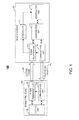
- FIG. 1 is a block diagram illustrating an example of a system for wireless power transmission including a transmitting device and a receiving device, in accordance with one embodiment of the present disclosure
- FIG. 2 is a block diagram illustrating an example of the receiving device shown in FIG. 1 , in accordance with one embodiment of the present disclosure
- FIG. 3 is a block diagram illustrating an example of the transmitting device shown in FIG. 1 , in accordance with one embodiment of the present disclosure
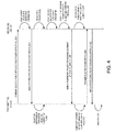
- FIG. 4 is a time line chart illustrating an example of wireless power transmission, in accordance with one embodiment of the present disclosure
- FIG. 5 is a time line chart illustrating another example of wireless power transmission, in accordance with one embodiment of the present disclosure.
- FIG. 6 is a flow chart illustrating an example of a method for wireless power transmission, in accordance with one embodiment of the present disclosure
- FIG. 7 is a flow chart illustrating another example of a method for wireless power transmission, in accordance with one embodiment of the present disclosure.
- FIG. 8 is a flow chart illustrating still another example of a method for wireless power transmission, in accordance with one embodiment of the present disclosure.
- FIG. 9 is a block diagram illustrating an example of an identification unit in the receiving device shown in FIG. 2 including a processor and a memory, in accordance with one embodiment of the present disclosure.
- FIG. 10 is a table illustrating an exemplary list of various packets for wireless power transmission, in accordance with one embodiment of the present disclosure.
- Various embodiments in accordance with the present disclosure provide a method and apparatus for identifying a maximum power capacity in wireless power transmission.
- the maximum power capacity is referred to the maximum power supported by a transmitting device or a receiving device in the wireless power transmission.
- a default power capacity i.e., a default value of supported maximum power
- the method and apparatus disclosed herein may allow the transmitting device and the receiving device to identify the maximum power capacity from each other. Therefore the transmitting device and the receiving device may configure a power capacity for wireless power transmission based on the identified maximum power capacity.
- the method and apparatus disclosed herein also support existing wireless power transmission standards, such as the QI communication protocol, and thus, are compatible with any QI-compatible transmitting or receiving device with 5W default power capacity.
- the method and apparatus disclosed herein may allow a transmitting device of 10W maximum power capacity to transmit electric power to a receiving device of 5 W maximum power capacity, at a power capacity 5W.
- the method and apparatus disclosed herein may allow a transmitting device of 5W maximum power capacity to transmit electric power to a receiving device of 10W maximum power capacity, at a power capacity 5W.
- the method and apparatus disclosed herein may allow a transmitting device of 10W maximum power capacity to transmit electric power to a receiving device of 10W maximum power capacity, at a power capacity 10W.
- FIG. 1 illustrates one example of a system 100 for wireless power transmission, in accordance with one embodiment of the present disclosure.
- the system 100 may be any suitable wireless power transmission system that includes a receiving device 102 and a transmitting device 104.
- Electric power 130 is wirelessly transmitted from the transmitting device 104 to the receiving device 102 by any known mechanism, such as but not limited to, resonant magnetic induction, electromagnetic radiation, or electrical conduction.
- the same mechanism for power transmission may be also used for sending control information from the receiving device 102 to the transmitting device 104 for adjusting any parameter, such as voltage, frequency, or duty cycle, associated with the electric power to a desired level.
- the control information may be sent via a standard packet being compatible with existing standards, such as the QI communication protocol.
- the control information may be sent via proprietary packets 140 agreed on by both the transmitting device 104 and the receiving device 102.
- the proprietary packets 140 may be not included in existing standards.
- the receiving device 102 may be part of an apparatus.
- the apparatus may be any suitable electronic device, such as but is not limited to, a laptop computer, netbook computer, digital camera, digital camcorder, handheld device (e.g., dumb or smart phone, tablet, etc.), gaming console, set-top box, music player, global positioning system (GPS), or any other suitable device.
- the receiving device 102 may be a discrete electronic device for providing power to a load.
- the receiving device 102 includes a power reception unit 110, a configuration unit 112, a reading unit 114, an identification unit 116, and a communication unit 118.
- the power reception unit 110 is configured to wirelessly receive electric power from the transmitting device 104.
- the configuration unit 112 is operatively coupled to the power reception unit 110 and is configured to configure a power capacity at the receiving device 102 for the wireless power transmission.
- the configuration unit 112 may configure a power capacity based on a default power capacity known by both the receiving device 102 and the transmitting device 104. The default power capacity may be compatible with the current QI communication protocol, which supports up to 5W power delivery.
- the configuration unit 112 may configure a power capacity based on a maximum power capacity of the transmitting device 104.
- the maximum power capacity of the transmitting device 104 may be greater than the default power capacity.
- the reading unit 114 is operatively coupled to the power reception unit 110 and is configured to read a first value and a second value of a dependent parameter associated with the electric power 130. The dependent parameter varies in accordance with an independent parameter adjustable by the transmitting device 104.
- the identification unit 116 is operatively coupled to the configuration unit 112 and the reading unit 114.
- the identification unit 116 is configured to identify a maximum power capacity of the transmitting device 104 based on at least the first and second values and a predetermined threshold.
- the communication unit 118 is operatively coupled to the configuration unit 112 and the power reception unit 110.
- the communication unit 118 is configured to send control information to the transmitting device 104.
- the control information may be sent in accordance with a communication protocol, such as the QI communication protocol, for example, by the same electromagnetic coupling mechanism used for power transmission.
- the control information in this example is sent via proprietary packets 140 agreed on by both the transmitting device 104 and the receiving device 102.
- the transmitting device 104 may be any suitable base station for wirelessly providing electric power to the receiving device 102.
- the transmitting device 104 includes a power transmission unit 120, a control unit 126, and a communication unit 128.
- the power transmission unit 120 is configured to wirelessly transmit the electric power 130 to the receiving device 102.
- the communication unit 128 is operatively coupled to the power transmission unit 120 and configured to receive the control information, via proprietary packets 140 in this example, from the receiving device 102.
- the control unit 126 is operatively coupled to the power transmission unit 120 and the communication unit 128.
- the control unit 126 is configured to, upon receiving a proprietary packet for adjustment from the receiving device 102, adjust the independent parameter based on content of the proprietary packet for adjustment.
- the configuration unit 112 of the receiving device 102 first configures a default power capacity at the receiving device 102.
- the reading unit 114 of the receiving device 102 then reads a first value of a dependent parameter associated with the electric power 130.
- the dependent parameter varies in accordance with an independent parameter adjustable by the transmitting device 104.
- the communication unit 118 of the receiving device 102 then sends a proprietary packet for adjustment to the transmitting device 104.
- the control unit 126 of the transmitting device 104 controls the power transmission unit 120 to adjust the independent parameter based on content of the proprietary packet for adjustment.
- the independent parameter is associated with the transmitted electric power 130.
- the reading unit 114 of the receiving device 102 then reads a second value of the dependent parameter, which varies in accordance with the adjustment of the independent parameter.
- the identification unit 116 identifies a maximum power capacity of the transmitting device 104 based on at least the first and second values and a predetermined threshold.
- FIG. 2 illustrates one example of the receiving device 102, in accordance with one embodiment of the present disclosure.
- the receiving device 102 includes the power reception unit 110 having a coil 202 and a rectifier 204.
- the coil 202 is responsible for receiving magnetic field by its resonant circuit and converting it to an AC voltage signal.
- the rectifier 204 is configured to convert the AC voltage signal to a DC voltage signal.
- An ADC monitor 206 may be employed to detect any suitable electrical parameter associated with the received electric power 130, e.g., voltage, current, or power, and provide it to the reading unit 114.
- the electrical parameter provided to the reading unit 114 may be a dependent parameter varying in accordance with an independent parameter adjustable by the transmitting device 104.
- the independent parameter may be voltage, frequency, or duty cycle.
- the receiving device 102 in this example also includes the communication unit 118 having the coil 202.
- the communication unit 118 is configured to send a proprietary packet to the transmitting device 104 for notifying the transmitting device 104 a maximum power capacity of the receiving device 102.
- the receiving device 102 in this example also includes a timer 208 operatively coupled to the reading unit 114 and the communication unit 118.
- the communication unit 118 sends a proprietary packet for adjustment to the transmitting device 104, within a time interval controlled by the timer 208.
- the reading unit 114 reads a second value of the dependent parameter, after the timer 208 delays for the time interval, within which the independent parameter has been adjusted by the transmitting device 104.
- the receiving device 102 in this example also includes the identification unit 116 having a processor 210, a comparison unit 212, and a determining unit 214.
- the processor 210 calculates an output of a function.
- the function has inputs of at least the first and second values.
- the comparison unit 212 then compares the output with the predetermined threshold and provides an output to the determining unit 214, which may determine the maximum power capacity 215 of the transmitting device 104 based on at least the output of the comparison unit 212.
- the determining unit 214 may provide the maximum power capacity 215 to the comparison unit 212, for which to compare the maximum power capacity 215 with the default power capacity 221.
- the configuration unit 112 configures a power capacity of the receiving device 102 based on the maximum power capacity 215 and the communication unit 118 sends a proprietary packet for acknowledgement and a proprietary packet for error control to the transmitting device 104.
- the identification unit 116 may be implemented by one or more processors 210 and memory 902.
- software programs and data may be loaded into the memory 902 and executed by the processor 210.
- the processor 210 may be any suitable processing unit, such as but not limited to, a microprocessor, a microcontroller, a central processing unit, an electronic control unit, etc.
- the memory 902 may be, for example, a discrete memory or a unified memory integrated with the processor 210.
- the data includes, for example, the first and second values 904, 906 of a dependent parameter, and a predetermined threshold 908.
- the dependent parameter is the DC voltage
- the predetermined threshold is set based on a function of the first and second values.
- FIG. 3 illustrates one example of the transmitting device 104, in accordance with one embodiment of the present disclosure.
- the transmitting device 104 includes a power transmission unit 120 having a PWM frequency unit 302 and a coil 304, a control unit 126, and a communication unit 128 having the coil 304.
- the communication unit 128 is responsible for receiving proprietary packets from the receiving device 102.
- the control unit 126 is configured to adjust a corresponding independent parameter.
- the independent parameter is a PWM frequency 303
- the control unit 126 is configured to control the PWM frequency unit 302 to adjust the frequency 303 to a desired level.
- the PWM frequency unit 302 is responsible for converting a DC voltage signal to an AC voltage signal
- the coil 304 is responsible for converting the electric field of the AC voltage signal to the magnetic field.
- the transmitting device 104 in this example also includes a configuration unit 306 and an analyzing unit 308.
- the configuration unit 306 may configure a power capacity based on the maximum power capacity of the transmitting device 104; if the proprietary packet for acknowledgement is not received by the communication unit 128, the configuration unit 306 may configure a power capacity based on the default power capacity.
- the power transmission unit 120 then wirelessly transmits the electric power 130 with the configured power capacity to the receiving device 102.
- the analyzing unit 308 may analyze the proprietary packet for error control.
- An ADC monitor 310 may also be included in the transmitting device 104 to provide levels of electrical parameters, such as voltage and current, to the control unit 126 for parameter adjustment, to the configuration unit 306 for power capacity configuration, and to the analyzing unit 308 for packet analysis.
- FIG. 4 is a time line chart illustrating an example of wireless power transmission, in accordance with one embodiment of the present disclosure.
- C_DEF default power capacity
- the default power capacity is 5W
- the default frequency is 175 kHz.
- the receiving device 102 reads a first value of a dependent parameter associated with the electric power, e.g., the output voltage. It is known that the output voltage of the received electric power varies in accordance with an independent parameter, e.g., the PWM frequency. The higher the PWM frequency is, the lower the output voltage is.
- the transmitting device 104 adjusts the PWM frequency to a target level different than the default frequency of 175 kHz, within a time interval.
- the target level of frequency is lower than the default frequency, e.g., 160 kHz.
- the target level of frequency is greater than the default frequency, e.g., 190 kHz.
- the receiving device 102 delays for the time interval and then reads a second value of the dependent parameter, or the output voltage in this example.
- the receiving device 102 then identifies the maximum power capacity (C_MAX) and compares it with C_DEF.
- the transmitting device 104 may be a device with relatively high load-driving capacity, e.g., a transmitting device with 10W C_MAX.
- the receiving device 102 in this example may identify C_MAX in the following way.
- the receiving device 102 first calculates a function of the two values of output voltage.
- An output of the function may be an absolute value of a difference between the two values.
- the output is compared by the receiving device 102 with a predetermined threshold, which may correspond to a desired change of output voltage in accordance with a given adjustment of the PWM frequency, e.g., from 175 kHz to 160 kHz.
- the receiving device 102 determines C_MAX based on a result of the comparison. For example, if the absolute value of the voltage difference is below a threshold, C_MAX may be identified to be the same as C_DEF, e.g., 5W in the current QI communication protocol. This is because the PWM frequency based on the QI communication protocol is fixed to 175 kHz, and hence the corresponding output voltage change is not very big. On the other hand, if the absolute value of the voltage difference is above a threshold, C_MAX may be identified to be a value greater than C_DEF, e.g., 10W.
- a proprietary packet for acknowledgement (P_ACK) is sent from the receiving device 102 to the transmitting device 104, if C_MAX is greater than C_DEF. Then both the transmitting and receiving devices 104, 102 configure a power capacity based on C_MAX. The electric power is then transmitted from the transmitting device 104 to the receiving device 102 at a frequency corresponding to a power capacity C_MAX. The receiving device 102 then regularly sends a proprietary packet for error control (P_EC) to the transmitting device 104, which analyzes P_EC to obtain data for control error.
- P_EC error control
- the receiving device 102 may notify the transmitting device 104 a maximum power capacity of the receiving device 102, by sending either a proprietary packet or a standard packet according to the QI communication protocol. As a consequence, the receiving device 102 and the transmitting device 104 know each other's maximum power capacity for wireless power transmission.
- FIG. 5 is a time line chart illustrating another example of wireless power transmission, in accordance with one embodiment of the present disclosure.
- the transmitting device 104 may be a device with relatively low load-driving capacity, e.g., a QI-compatible 5W transmitting device.
- the C_MAX identified by the receiving device 102 may be not greater than C_DEF.
- the transmitting device 104 may not receive P_ACK from the receiving device 102.
- both the transmitting and receiving devices 104, 102 configure or keep a power capacity based on C_DEF.
- the electric power is then transmitted from the transmitting device 104 to the receiving device 102 at a frequency corresponding to a power capacity C_DEF.
- the receiving device 102 does not have to send proprietary packets and may send standard packets including a control error packet according to the QI communication protocol. Accordingly, the receiving device 102 may support wireless power transmissions both with C_DEF and with a C_MAX that is greater than C_DEF. By doing so, the receiving device 102 is able to adaptively receive electric power with a wide range of power capacity while still being compatible with existing standards, such as the QI communication protocol.
- embodiments of the present disclosure enable compatible wireless power transmissions between a high C_MAX transmitter and a low C_DEF receiver, between a low C_DEF transmitter and a high C_MAX receiver, and between a high C_MAX transmitter and a high C_MAX receiver.
- a receiver is not able to or not configured to support a power capacity higher than C_DEF. In that situation, no P_ADJ will be sent to a corresponding transmitter, and wireless power may be transmitted from the transmitter to the receiver with the default power capacity C_DEF.
- FIG. 6 depicts one example of a method for wireless power transmission, in accordance with one embodiment of the present disclosure. It will be described with reference to the above figures. However, any suitable unit may be employed. Beginning at block 602, a power capacity is configured at the receiving device 102 based on a default power capacity known by both the receiving device 102 and the transmitting device 104. Proceeding to block 604, a first value of a dependent parameter is read. The dependent parameter varies in accordance with an independent parameter adjustable by the transmitting device 104. Moving to block 606, after the independent parameter is adjusted by the transmitting device 104, a second value of the dependent parameter is read.
- blocks 602-610 may be performed by the receiving device 102.
- FIG. 7 depicts another example of the method for wireless power transmission, in accordance with one embodiment of the present disclosure. It will be described with reference to the above figures. However, any suitable unit may be employed.
- the wireless power transmission starts with an identification and configuration phase.
- a power capacity is configured at the receiving device 102 based on a default power capacity C_DEF known by both the receiving device 102 and the transmitting device 104. As described above, this may be performed by the configuration unit 112 of the receiving device 102.
- a first value of a dependent parameter is read.
- the dependent parameter includes, for example, voltage, current, and power, and varies in accordance with an independent parameter adjustable by the transmitting device 104.
- the independent parameter includes, for example, voltage, frequency, and duty cycle.
- the receiving device 102 may send a standard or proprietary packet to the transmitting device 104 for notifying the transmitting device 104 a maximum power capacity of the receiving device 102 (not shown in FIG. 7 ).
- a proprietary packet for adjustment P_ADJ is sent to the transmitting device 104, and reading operation is delayed for a time interval.
- a time interval between two consecutive packets is set as 0 to 21 ms. Accordingly in this example, the time interval delayed after sending P_ADJ may be about 10 ms.
- the transmitting device 104 adjusts the independent parameter (e.g., frequency) based on content of P_ADJ. And at block 708, a second value of the dependent parameter is read after the delay.
- blocks 704, 706, and 708 may be performed by the reading unit 114 in conjunction with the communication unit 118 and the timer 208 of the receiving device 102.
- the receiving device 102 is not able to or not configured to support a power capacity higher than C_DEF. In that situation, the receiving device 102 may not send P_ADJ to the transmitting device 104 and does not have to read values of the dependent parameter. Accordingly, wireless power may be transmitted from the transmitting device 104 to the receiving device 102 with the default power capacity C_DEF.
- an output of a function is calculated.
- the function has inputs of at least the first and second values.
- the output is compared with a predetermined threshold.
- a maximum power capacity C_MAX of the transmitting device 104 is determined based on at least a result of the comparison in 712, and is compared with a default power capacity C_DEF.
- a second P_ADJ may be sent to the transmitting device 104. Accordingly, a third value of the dependent parameter may be read.
- a function may be calculated with inputs of the three values and two outputs, which may be compared with two predetermined thresholds.
- C_MAX may be determined based on results of the two comparisons.
- the independent parameter may be frequency at the transmitting device 104, which is set to default value of 175 kHz at first, and then adjusted to 160 kHz and 190 kHz based on contents of the two P_ADJs.
- the dependent parameter may be output voltage at the receiving device 102, which varies in accordance with the frequency.
- blocks 710, 712, and 714 may be performed by the processor 210, the comparison unit 212, and the determining unit 214 in the identification unit 116 of the receiving device 102.
- C_MAX is greater than C_DEF. This may be performed by the comparison unit 212 or another comparison unit of the receiving device 102. If C_MAX is greater than C_DEF, process continues to block 718, where a power capacity is configured based on C_MAX. As described above, this may be performed by the configuration unit 112 of the receiving device 102.
- a proprietary packet for acknowledgement (P_ACK) is sent for acknowledging the transmitting device the determination of C_MAX and the configuration based on C_MAX. This may be performed by the communication unit 118.
- the identification and configuration phase may end by sending a configuration packet (not shown in FIG. 7 ), in accordance with the QI communication protocol.
- the wireless power transmission enters a power transfer phase.
- the electric power is received at the receiving device 102 with a power capacity C_MAX, and a proprietary packet for error control (P_EC) is sent to the transmitting device 104.
- P_EC packet for error control
- this may be performed by the power reception unit 110 in conjunction with the communication unit 118 of the receiving device 102.
- more proprietary packets may be sent regularly in the power transfer phase.
- FIG. 10 For example, a list of various packets is illustrated in FIG. 10 , with formats according to the QI communication protocol.
- the table in FIG. 10 includes column 1002 showing headers for various packets, column 1004 showing packet types for corresponding packets, and column 1006 showing message sizes with byte as a unit for corresponding packets.
- the corresponding packet type and message size for the packet can be identified.
- Proprietary shown in column 1004 denotes a proprietary packet, which may have an extended definition in a specific example and may be used in both the identification and configuration phase and the power transfer phase.
- 0x18 may be used for P_ADJ in the identification and configuration phase
- 0x19 may be used for P_ACK in the identification and configuration phase
- 0x19 may be used for P_EC in the power transfer phase while 0x03 is kept with a control error value of 0.
- FIG. 8 depicts still another example of the method for wireless power transmission, in accordance with one embodiment of the present disclosure. It will be described with reference to the above figures. However, any suitable unit may be employed.
- the wireless power transmission starts with the identification and configuration phase.
- C_MAX of the receiving device 102 is received. This may be performed by the communication unit 128 of the transmitting device 104.
- a power capacity is configured based on C_DEF. As described above, this may be performed by the configuration unit 306 of the transmitting device 104.
- the electric power with a frequency determined based on a power capacity C_DEF is transmitted to the receiving device 102. As described above, this may be performed by the power transmission unit 120 of the transmitting device 104.
- the proprietary packet P_ADJ is received at the transmitting device 104. This may be performed by the communication unit 128 in conjunction with the ADC monitor 310.
- an independent parameter is adjusted based on content of P_ADJ.
- the independent parameter may be voltage, frequency, or duty cycle of frequency. As described above, this may be performed by the control unit 126 in conjunction with the PWM frequency unit 302 in the power transmission unit 120 of the transmitting device 104.
- the proprietary packet P_ACK is determined. This may be performed by the control unit 126 in conjunction with the ADC monitor 310 of the transmitting device 104. If P_ACK has been received, process continues to block 814, where a power capacity is configured based on C_MAX of the transmitting device 104. As described above, this may be performed by the configuration unit 306 of the transmitting device 104.
- the wireless power transmission enters the power transfer phase. The electric power is transmitted to the receiving device 102 with a power capacity C_MAX. This may be performed by the power transmission unit 120 of the transmitting device 104.
- the proprietary packet P_EC is received and analyzed at the transmitting device 104. As described above, this may be performed by the analyzing unit 308 in conjunction with the communication unit 128 and the ADC monitor 310 of the transmitting device 104.
- process goes to block 830, where the wireless power transmission enters the power transfer phase, and the electric power is transmitted with a power capacity C_DEF.
- this may be performed by the power transmission unit 120 of the transmitting device 104, maybe in conjunction with the configuration unit 306 and the control unit 126.
- aspects of the method for wireless power transmission may be embodied in programming.
- Program aspects of the technology may be thought of as “products” or “articles of manufacture” typically in the form of executable code and/or associated data that is carried on or embodied in a type of machine readable medium.
- Tangible non-transitory “storage” type media include any or all of the memory or other storage for the computers, processors or the like, or associated modules thereof, such as various semiconductor memories, tape drives, disk drives and the like, which may provide storage at any time for the computer-implemented method.
- All or portions of the computer-implemented method may at times be communicated through a network such as the Internet or various other telecommunication networks. Such communications, for example, may enable loading of the software from one computer or processor into another.
- another type of media that may bear the elements of the computer-implemented method includes optical, electrical, and electromagnetic waves, such as used across physical interfaces between local devices, through wired and optical landline networks and over various air-links.
- the physical elements that carry such waves, such as wired or wireless links, optical links or the like, also may be considered as media bearing the computer-implemented method.
- terms such as computer or machine "readable medium” refer to any medium that participates in providing instructions to a processor for execution.
- Non-volatile storage media include, for example, optical or magnetic disks, such as any of the storage devices in any computer(s) or the like, which may be used to implement the system or any of its components as shown in the drawings.
- Volatile storage media include dynamic memory, such as a main memory of such a computer platform.
- Tangible transmission media include coaxial cables; copper wire and fiber optics, including the wires that form a bus within a computer system.
- Carrier-wave transmission media can take the form of electric or electromagnetic signals, or acoustic or light waves such as those generated during radio frequency (RF) and infrared (IR) data communications.
- Computer-readable media therefore include for example: a floppy disk, a flexible disk, hard disk, magnetic tape, any other magnetic medium, a CD-ROM, DVD or DVD-ROM, any other optical medium, punch cards paper tape, any other physical storage medium with patterns of holes, a RAM, a PROM and EPROM, a FLASH-EPROM, any other memory chip or cartridge, a carrier wave transporting data or instructions, cables or links transporting such a carrier wave, or any other medium from which a computer can read programming code and/or data. Many of these forms of computer readable media may be involved in carrying one or more sequences of one or more instructions to a processor for execution.
Landscapes
- Engineering & Computer Science (AREA)
- Power Engineering (AREA)
- Computer Networks & Wireless Communication (AREA)
- Signal Processing (AREA)
- Charge And Discharge Circuits For Batteries Or The Like (AREA)
- Mobile Radio Communication Systems (AREA)
Applications Claiming Priority (1)
| Application Number | Priority Date | Filing Date | Title |
|---|---|---|---|
| US13/667,024 US9276435B2 (en) | 2012-11-02 | 2012-11-02 | Method and apparatus for wirelessly receiving power |
Publications (1)
| Publication Number | Publication Date |
|---|---|
| EP2728705A2 true EP2728705A2 (de) | 2014-05-07 |
Family
ID=49328439
Family Applications (1)
| Application Number | Title | Priority Date | Filing Date |
|---|---|---|---|
| EP13188520.4A Withdrawn EP2728705A2 (de) | 2012-11-02 | 2013-10-14 | Verfahren und Vorrichtung zum drahtlosen Empfang von Strom |
Country Status (6)
| Country | Link |
|---|---|
| US (1) | US9276435B2 (de) |
| EP (1) | EP2728705A2 (de) |
| JP (1) | JP2014093940A (de) |
| KR (1) | KR20140057151A (de) |
| CN (1) | CN103812159A (de) |
| TW (1) | TW201419702A (de) |
Cited By (2)
| Publication number | Priority date | Publication date | Assignee | Title |
|---|---|---|---|---|
| EP3451492A1 (de) * | 2017-08-29 | 2019-03-06 | Beijing Xiaomi Mobile Software Co., Ltd. | Verfahren, sender, empfänger und leistungsverwaltungsvorrichtung für drahtloses laden |
| RU2704726C1 (ru) * | 2017-07-31 | 2019-10-30 | Бейджин Сяоми Мобайл Софтвеа Ко., Лтд. | Способ и терминал для беспроводной зарядки |
Families Citing this family (20)
| Publication number | Priority date | Publication date | Assignee | Title |
|---|---|---|---|---|
| CN106134031A (zh) * | 2014-02-22 | 2016-11-16 | 胡玛沃克斯公司 | 无线充电设备以及使用方法 |
| MX352346B (es) * | 2014-03-31 | 2017-11-22 | Koninklijke Philips Nv | Transferencia de energía inductiva de forma inalámbrica. |
| KR101750345B1 (ko) | 2014-06-05 | 2017-07-03 | 엘지전자 주식회사 | 무선 전력 전송방법, 무선 전력 전송장치 및 무선 충전 시스템 |
| WO2015186991A1 (en) * | 2014-06-05 | 2015-12-10 | Lg Electronics Inc. | Wireless power transfer method, apparatus and system |
| WO2015190828A1 (en) * | 2014-06-13 | 2015-12-17 | Lg Electronics Inc. | Wireless power transfer method, apparatus and system |
| KR101731923B1 (ko) | 2014-06-13 | 2017-05-02 | 엘지전자 주식회사 | 무선 전력 전송방법, 무선 전력 전송장치 및 무선 충전 시스템 |
| DE102014212530A1 (de) * | 2014-06-30 | 2015-12-31 | Schaeffler Technologies AG & Co. KG | Sensoranordnung sowie Wälzlager mit einer solchen |
| CN105896639B (zh) * | 2015-01-26 | 2020-11-20 | 联想(北京)有限公司 | 一种充电控制方法和电子设备 |
| US10418855B2 (en) * | 2015-08-10 | 2019-09-17 | Qualcomm Incorporated | Method and apparatus for varying a wireless charging category of a wireless power receiver in wireless charging applications |
| US20170110901A1 (en) * | 2015-10-16 | 2017-04-20 | Droneventory Corporation | Battery profile translator and remote charging system and method |
| CN109952503B (zh) * | 2016-07-01 | 2022-09-09 | Lg伊诺特有限公司 | 用于检测异物的方法及其设备和系统 |
| KR20190011077A (ko) * | 2017-07-24 | 2019-02-01 | 엘지이노텍 주식회사 | 무선 충전 시 거짓 충전 상태를 감지하여 충전 과정을 제어하는 방법 및 장치 |
| US11575459B2 (en) | 2018-04-05 | 2023-02-07 | Rutgers, The State University Of New Jersey | Secure communications through distributed phase alignment |
| ES3008934T3 (en) | 2018-04-16 | 2025-03-25 | Lg Electronics Inc | Apparatus and method for performing transmission of data stream in wireless power transmission system |
| HUE060263T2 (hu) * | 2018-10-26 | 2023-02-28 | Lg Electronics Inc | Berendezés adatok átvitelére vagy vételére vezték nélküli energiaátviteli rendszerben |
| WO2020153761A1 (ko) * | 2019-01-22 | 2020-07-30 | 엘지전자 주식회사 | 무선전력 수신장치 및 무선전력 전송장치 |
| KR102659965B1 (ko) * | 2019-07-31 | 2024-04-24 | 삼성전자 주식회사 | 전자 장치 및 그의 주파수 간섭 제어 방법 |
| KR102811174B1 (ko) | 2020-02-10 | 2025-05-22 | 삼성전자주식회사 | 무선 전력 전송 중 통신 성능 안정화 방법 및 장치 |
| TWI769446B (zh) * | 2020-04-14 | 2022-07-01 | 陳順珍 | 複數免電池無線供電系統 |
| CN114500204B (zh) * | 2022-03-30 | 2022-07-19 | 浙江地芯引力科技有限公司 | Fsk数据发送控制装置、方法、定时器、mcu及设备 |
Family Cites Families (15)
| Publication number | Priority date | Publication date | Assignee | Title |
|---|---|---|---|---|
| US20030072273A1 (en) * | 2001-09-07 | 2003-04-17 | Aiello G. Roberto | System and method for transmitting data in Ultra Wide Band frequencies in a de-centralized system |
| US6898193B2 (en) * | 2002-06-20 | 2005-05-24 | Qualcomm, Incorporated | Adaptive gain adjustment control |
| JP4196100B2 (ja) | 2003-10-28 | 2008-12-17 | パナソニック電工株式会社 | 非接触給電装置 |
| US8099140B2 (en) * | 2006-11-24 | 2012-01-17 | Semiconductor Energy Laboratory Co., Ltd. | Wireless power supply system and wireless power supply method |
| US7983204B2 (en) * | 2007-11-27 | 2011-07-19 | Motorola Mobility, Inc. | Wirelesss communication device and method |
| JP2009251895A (ja) | 2008-04-04 | 2009-10-29 | Sony Corp | 電力交換装置、電力交換方法、プログラム、および電力交換システム |
| JP4544338B2 (ja) | 2008-04-28 | 2010-09-15 | ソニー株式会社 | 送電装置、受電装置、送電方法、プログラム、および電力伝送システム |
| JP2010011650A (ja) | 2008-06-27 | 2010-01-14 | Seiko Epson Corp | 送電制御装置、送電装置、電子機器、及び送電制御方法 |
| MY159639A (en) | 2008-07-09 | 2017-01-13 | Access Business Group Int Llc | Wireless charging system |
| JP4725611B2 (ja) | 2008-07-16 | 2011-07-13 | セイコーエプソン株式会社 | 送電制御装置、送電装置、受電制御装置、受電装置及び電子機器 |
| JP2010104098A (ja) | 2008-10-21 | 2010-05-06 | Seiko Epson Corp | 認証処理装置、受電装置、送電装置、及び電子機器 |
| BR112012025873A2 (pt) | 2010-04-13 | 2016-06-28 | Fujitsu Ltd | sistema de fornecimento de energia, transmissor de energia e receptor de energia |
| US9065302B2 (en) | 2010-12-24 | 2015-06-23 | Semiconductor Energy Laboratory Co., Ltd. | Wireless power feeding system |
| CN102593957A (zh) | 2011-01-18 | 2012-07-18 | 深圳市博巨兴实业发展有限公司 | 一种无线充电发射端、接收端和无线充电装置 |
| JP2012205379A (ja) | 2011-03-25 | 2012-10-22 | Sanyo Electric Co Ltd | 充電システム、電源装置、移動体、無線電力送受電システム及び受電装置 |
-
2012
- 2012-11-02 US US13/667,024 patent/US9276435B2/en active Active
-
2013
- 2013-07-10 CN CN201310289192.8A patent/CN103812159A/zh active Pending
- 2013-08-29 TW TW102131063A patent/TW201419702A/zh unknown
- 2013-10-04 KR KR1020130118692A patent/KR20140057151A/ko not_active Ceased
- 2013-10-07 JP JP2013210107A patent/JP2014093940A/ja active Pending
- 2013-10-14 EP EP13188520.4A patent/EP2728705A2/de not_active Withdrawn
Non-Patent Citations (1)
| Title |
|---|
| None |
Cited By (4)
| Publication number | Priority date | Publication date | Assignee | Title |
|---|---|---|---|---|
| RU2704726C1 (ru) * | 2017-07-31 | 2019-10-30 | Бейджин Сяоми Мобайл Софтвеа Ко., Лтд. | Способ и терминал для беспроводной зарядки |
| US10734832B2 (en) | 2017-07-31 | 2020-08-04 | Beijing Xiaomi Mobile Software Co., Ltd. | Method and terminal for wireless charging |
| EP3451492A1 (de) * | 2017-08-29 | 2019-03-06 | Beijing Xiaomi Mobile Software Co., Ltd. | Verfahren, sender, empfänger und leistungsverwaltungsvorrichtung für drahtloses laden |
| US10992189B2 (en) | 2017-08-29 | 2021-04-27 | Beijing Xiaomi Mobile Software Co., Ltd. | Method for wireless charging, transmitter, receiver and power management apparatus |
Also Published As
| Publication number | Publication date |
|---|---|
| KR20140057151A (ko) | 2014-05-12 |
| JP2014093940A (ja) | 2014-05-19 |
| US20140125138A1 (en) | 2014-05-08 |
| CN103812159A (zh) | 2014-05-21 |
| US9276435B2 (en) | 2016-03-01 |
| TW201419702A (zh) | 2014-05-16 |
Similar Documents
| Publication | Publication Date | Title |
|---|---|---|
| US9276435B2 (en) | Method and apparatus for wirelessly receiving power | |
| EP2728706A2 (de) | Verfahren und Vorrichtung zur drahtlosen Stromübertragung | |
| US20250167831A1 (en) | Device and method for performing authentication in wireless power transmission system | |
| US11641220B2 (en) | Apparatus and method for performing data stream transmission in wireless power transfer system | |
| US10749574B2 (en) | Device and method for performing authentication in wireless power transfer system | |
| EP3734795B1 (de) | Vorrichtung und verfahren zur durchführung von stromregelung in einem system zur drahtlosen stromübertragung | |
| US9685791B2 (en) | Apparatus and method for controlling wireless power transfer to mobile devices | |
| US20200252886A1 (en) | Device and method for performing authentication in wireless power transmission system | |
| EP4250524B1 (de) | Vorrichtung und verfahren zur durchführung von stromregelung in einem system zur drahtlosen stromübertragung | |
| EP3347966B1 (de) | Drahtloser stromempfänger und verfahren zur steuerung des drahtlosen stromempfängers | |
| JP2015536633A (ja) | 無線誘導電力伝送 | |
| US20200328631A1 (en) | Device and method for performing authentication in wireless power transfer system | |
| US10879962B2 (en) | Device and method for performing authentication in wireless power transfer system | |
| US9151623B2 (en) | Method and apparatus for controlling an electrical device and a wireless charging device | |
| CN107996013A (zh) | 用于替代电源无线充电的方法、系统和装置 | |
| EP3046221A1 (de) | Kontaktloses transformatordetektionsverfahren, vorrichtung und computerspeichermedium | |
| WO2025174310A1 (en) | Backscatter signal strength by constructive addition of harmonics | |
| JP2014093607A (ja) | 通信システム、通信装置、送信パワー制御方法および制御プログラム |
Legal Events
| Date | Code | Title | Description |
|---|---|---|---|
| PUAI | Public reference made under article 153(3) epc to a published international application that has entered the european phase |
Free format text: ORIGINAL CODE: 0009012 |
|
| 17P | Request for examination filed |
Effective date: 20131014 |
|
| AK | Designated contracting states |
Kind code of ref document: A2 Designated state(s): AL AT BE BG CH CY CZ DE DK EE ES FI FR GB GR HR HU IE IS IT LI LT LU LV MC MK MT NL NO PL PT RO RS SE SI SK SM TR |
|
| AX | Request for extension of the european patent |
Extension state: BA ME |
|
| STAA | Information on the status of an ep patent application or granted ep patent |
Free format text: STATUS: THE APPLICATION IS DEEMED TO BE WITHDRAWN |
|
| 18D | Application deemed to be withdrawn |
Effective date: 20160503 |