EP2728335B1 - Tensile test device for testing deposits on electronic substrates - Google Patents
Tensile test device for testing deposits on electronic substrates Download PDFInfo
- Publication number
- EP2728335B1 EP2728335B1 EP14153545.0A EP14153545A EP2728335B1 EP 2728335 B1 EP2728335 B1 EP 2728335B1 EP 14153545 A EP14153545 A EP 14153545A EP 2728335 B1 EP2728335 B1 EP 2728335B1
- Authority
- EP
- European Patent Office
- Prior art keywords
- jaw
- machine
- test
- rigid members
- deposit
- Prior art date
- Legal status (The legal status is an assumption and is not a legal conclusion. Google has not performed a legal analysis and makes no representation as to the accuracy of the status listed.)
- Ceased
Links
- 238000012360 testing method Methods 0.000 title claims description 55
- 239000000758 substrate Substances 0.000 title claims description 15
- 238000009864 tensile test Methods 0.000 title claims description 9
- 230000033001 locomotion Effects 0.000 claims description 14
- 238000005259 measurement Methods 0.000 claims description 4
- 229910000679 solder Inorganic materials 0.000 description 14
- 238000005452 bending Methods 0.000 description 7
- 238000006073 displacement reaction Methods 0.000 description 5
- 238000013459 approach Methods 0.000 description 3
- 238000000034 method Methods 0.000 description 3
- 229910001220 stainless steel Inorganic materials 0.000 description 3
- 239000010935 stainless steel Substances 0.000 description 3
- 230000005540 biological transmission Effects 0.000 description 2
- 239000011888 foil Substances 0.000 description 2
- 239000000463 material Substances 0.000 description 2
- 238000001259 photo etching Methods 0.000 description 2
- 230000036316 preload Effects 0.000 description 2
- 206010010904 Convulsion Diseases 0.000 description 1
- 229910001315 Tool steel Inorganic materials 0.000 description 1
- 239000000853 adhesive Substances 0.000 description 1
- 230000001070 adhesive effect Effects 0.000 description 1
- 239000004411 aluminium Substances 0.000 description 1
- 229910052782 aluminium Inorganic materials 0.000 description 1
- XAGFODPZIPBFFR-UHFFFAOYSA-N aluminium Chemical compound [Al] XAGFODPZIPBFFR-UHFFFAOYSA-N 0.000 description 1
- 238000004458 analytical method Methods 0.000 description 1
- 238000003491 array Methods 0.000 description 1
- 230000000052 comparative effect Effects 0.000 description 1
- 230000006835 compression Effects 0.000 description 1
- 238000007906 compression Methods 0.000 description 1
- 230000002596 correlated effect Effects 0.000 description 1
- 230000000875 corresponding effect Effects 0.000 description 1
- 238000011161 development Methods 0.000 description 1
- 230000000694 effects Effects 0.000 description 1
- 238000009863 impact test Methods 0.000 description 1
- 238000005304 joining Methods 0.000 description 1
- 238000003754 machining Methods 0.000 description 1
- 230000014759 maintenance of location Effects 0.000 description 1
- 238000004519 manufacturing process Methods 0.000 description 1
- 230000013011 mating Effects 0.000 description 1
- 229910052751 metal Inorganic materials 0.000 description 1
- 239000002184 metal Substances 0.000 description 1
- 238000003801 milling Methods 0.000 description 1
- 230000007935 neutral effect Effects 0.000 description 1
- 230000037361 pathway Effects 0.000 description 1
- 230000000750 progressive effect Effects 0.000 description 1
- 239000004065 semiconductor Substances 0.000 description 1
- 230000035945 sensitivity Effects 0.000 description 1
- 230000035939 shock Effects 0.000 description 1
- 238000004904 shortening Methods 0.000 description 1
- 238000005476 soldering Methods 0.000 description 1
- 230000000007 visual effect Effects 0.000 description 1
Images


Classifications
-
- G—PHYSICS
- G01—MEASURING; TESTING
- G01N—INVESTIGATING OR ANALYSING MATERIALS BY DETERMINING THEIR CHEMICAL OR PHYSICAL PROPERTIES
- G01N3/00—Investigating strength properties of solid materials by application of mechanical stress
- G01N3/08—Investigating strength properties of solid materials by application of mechanical stress by applying steady tensile or compressive forces
-
- G—PHYSICS
- G01—MEASURING; TESTING
- G01N—INVESTIGATING OR ANALYSING MATERIALS BY DETERMINING THEIR CHEMICAL OR PHYSICAL PROPERTIES
- G01N3/00—Investigating strength properties of solid materials by application of mechanical stress
-
- G—PHYSICS
- G01—MEASURING; TESTING
- G01N—INVESTIGATING OR ANALYSING MATERIALS BY DETERMINING THEIR CHEMICAL OR PHYSICAL PROPERTIES
- G01N3/00—Investigating strength properties of solid materials by application of mechanical stress
- G01N3/02—Details
- G01N3/04—Chucks
-
- G—PHYSICS
- G01—MEASURING; TESTING
- G01N—INVESTIGATING OR ANALYSING MATERIALS BY DETERMINING THEIR CHEMICAL OR PHYSICAL PROPERTIES
- G01N19/00—Investigating materials by mechanical methods
- G01N19/04—Measuring adhesive force between materials, e.g. of sealing tape, of coating
-
- G—PHYSICS
- G01—MEASURING; TESTING
- G01N—INVESTIGATING OR ANALYSING MATERIALS BY DETERMINING THEIR CHEMICAL OR PHYSICAL PROPERTIES
- G01N2203/00—Investigating strength properties of solid materials by application of mechanical stress
- G01N2203/0014—Type of force applied
- G01N2203/0016—Tensile or compressive
- G01N2203/0017—Tensile
-
- G—PHYSICS
- G01—MEASURING; TESTING
- G01N—INVESTIGATING OR ANALYSING MATERIALS BY DETERMINING THEIR CHEMICAL OR PHYSICAL PROPERTIES
- G01N2203/00—Investigating strength properties of solid materials by application of mechanical stress
- G01N2203/003—Generation of the force
- G01N2203/0042—Pneumatic or hydraulic means
- G01N2203/0044—Pneumatic means
-
- G—PHYSICS
- G01—MEASURING; TESTING
- G01N—INVESTIGATING OR ANALYSING MATERIALS BY DETERMINING THEIR CHEMICAL OR PHYSICAL PROPERTIES
- G01N2203/00—Investigating strength properties of solid materials by application of mechanical stress
- G01N2203/003—Generation of the force
- G01N2203/005—Electromagnetic means
- G01N2203/0051—Piezoelectric means
-
- G—PHYSICS
- G01—MEASURING; TESTING
- G01N—INVESTIGATING OR ANALYSING MATERIALS BY DETERMINING THEIR CHEMICAL OR PHYSICAL PROPERTIES
- G01N2203/00—Investigating strength properties of solid materials by application of mechanical stress
- G01N2203/02—Details not specific for a particular testing method
- G01N2203/022—Environment of the test
- G01N2203/0248—Tests "on-line" during fabrication
-
- G—PHYSICS
- G01—MEASURING; TESTING
- G01N—INVESTIGATING OR ANALYSING MATERIALS BY DETERMINING THEIR CHEMICAL OR PHYSICAL PROPERTIES
- G01N2203/00—Investigating strength properties of solid materials by application of mechanical stress
- G01N2203/02—Details not specific for a particular testing method
- G01N2203/026—Specifications of the specimen
- G01N2203/0286—Miniature specimen; Testing on microregions of a specimen
-
- G—PHYSICS
- G01—MEASURING; TESTING
- G01N—INVESTIGATING OR ANALYSING MATERIALS BY DETERMINING THEIR CHEMICAL OR PHYSICAL PROPERTIES
- G01N2203/00—Investigating strength properties of solid materials by application of mechanical stress
- G01N2203/02—Details not specific for a particular testing method
- G01N2203/026—Specifications of the specimen
- G01N2203/0296—Welds
-
- G—PHYSICS
- G01—MEASURING; TESTING
- G01N—INVESTIGATING OR ANALYSING MATERIALS BY DETERMINING THEIR CHEMICAL OR PHYSICAL PROPERTIES
- G01N2203/00—Investigating strength properties of solid materials by application of mechanical stress
- G01N2203/02—Details not specific for a particular testing method
- G01N2203/04—Chucks, fixtures, jaws, holders or anvils
- G01N2203/0411—Chucks, fixtures, jaws, holders or anvils using pneumatic or hydraulic pressure
-
- G—PHYSICS
- G01—MEASURING; TESTING
- G01N—INVESTIGATING OR ANALYSING MATERIALS BY DETERMINING THEIR CHEMICAL OR PHYSICAL PROPERTIES
- G01N2203/00—Investigating strength properties of solid materials by application of mechanical stress
- G01N2203/02—Details not specific for a particular testing method
- G01N2203/06—Indicating or recording means; Sensing means
- G01N2203/0617—Electrical or magnetic indicating, recording or sensing means
- G01N2203/0623—Electrical or magnetic indicating, recording or sensing means using piezoelectric gauges
Definitions
- This invention relates to a device for performing a pull test on miniature metallic bonds of electrical equipment.
- a substrate for use in electrical apparatus typically defines electrical pathways for connecting electrical components thereof.
- electrical connections to the substrate are made via soldered or welded connections, and for this purpose metallic balls, for example of solder, are formed on the component and re-flowed or welded when assembled to a mating substrate.
- a component may be in the range 5-50mm and have solder balls thereon.
- Such components are often termed BGA's (ball grid arrays). These balls have the appearance of a low circular dome or squashed sphere, and have a diameter in the range 0.1-1.0mm.
- solder balls and/or the low detected forces have resulted in the development of specialist test equipment.
- Such equipment may be semi-automated so that successive balls on a component are indexed one by one to a test position, for pull testing.
- devices have been developed with jaws to grip a solder ball so as to exert a pulling (tension) load.
- the pulling load is applied generally perpendicular to the bonding plane.
- Very low forces are detected by the use of special low friction techniques.
- One aim of the present invention is thus to provide a low mass arrangement capable of exerting high gripping forces at the gripping head, and also capable of high speed testing.
- 'high speed' means greater than 15 mm/s, and as high as 1000 mm/s.
- Conventional testing, in which a gripper pulls a deposit off a substrate, is typically in the range 0.1-15 mm/s, and is referred to in this specification, comparatively, as 'low speed' testing.
- WO 2005/114722 discloses a device for shear testing of miniature metallic bonds
- Document US6237422 discloses a tensile test machine for testing miniature bonds, having a jaw for gripping a deposit on a substrate, the jaw having two rigig members.
- the invention provides a tensile test machine for testing miniature metallic bonds of electrical equipment, the machine having a jaw for gripping a deposit on a substrate, the jaw having two rigid members, each of the rigid members having a first upper end and an oppositely disposed second lower end, characterised in that the jaw has a central member connecting the two rigid members, and the machine has a beam which is supported on said machine, the jaw being attached to the beam, force measurement elements provided on the beam and an actuating mechanism supported on said machine, the first ends of the rigid members being attached by tension elements to said actuating mechanism, said actuating mechanism being suited to apply a tension force to said tension members to pull said first ends of said rigid members away from one another, said movement of said first ends away from one another causing said second ends to move towards one another to grip said deposit.
- the beam is moved upward by the test device so that an upward tensile force is transmitted to the central member, or cross piece, and thence to the test sample via the lower ends of the rigid members which are uprights.
- the upper ends of the uprights which are being pulled apart to cause the jaw to grip the sample are substantially isolated from this tensile force load path.
- Such a jaw can be formed by photo-etching from, for example, stainless steel sheet.
- the uprights are arranged to bend resiliently about the cross piece in the manner of a living hinge.
- the cross piece is typically of smaller section than the uprights at least at the ends thereof.
- the uprights themselves are however relatively stiff so as to be able to grip the test sample without bending, and are of comparatively large section relative to the ends of the cross piece.
- the uprights may include apertures to reduce the mass thereof, especially by removal of material from low stress areas, for example on the neutral axis thereof.
- the jaw is no more than 10g in weight, and in one example is less than 5g in weight.
- the said other ends of the uprights may approach so as to define a narrow jaw gap suited to the maximum dimension of the sample to be gripped.
- the other ends may be shaped to better conform to the shape of the sample.
- the jaw is symmetrical.
- the beam is a cantilever beam
- the jaw is mounted to the free end of the cantilever beam
- the beam axis is substantially orthogonal to the axis of said uprights and to the axis of said cross piece.
- said beam incorporates one or more strain gauges to relate deflection thereof to applied force.
- said beam incorporates one or more strain gauges to relate deflection thereof to applied force.
- the cantilever beam comprises a multi-component device having a main beam element comprising a cantilever spring and a minor beam element connected at its ends to the main beam element, and acting as a force detecting member.
- the minor beam element is typically strain gauged to allow bending thereof to be related to the force applied to the sample.
- the main beam element may have a minor beam element on either side thereof.
- the beam comprises three parallel beam elements having ends connected at one side to said jaw, and at the other side being connectable to a main frame element. Multiple parallel beam elements are desirable in order to ensure that jaw movement is on a single (typically vertical) axis, rather than in an arc.
- the uprights are actuated by respective tension elements directed oppositely.
- tension elements By utilising tension elements, the mass and stiffness thereof can be low compared with compression elements.
- Flexible tension elements effectively de-couple the mass of the actuator for the tension elements from the mass of the jaw and cantilever beam by resisting transmission of forces from the actuator to the jaw except for the tensile forces used to actuate the jaw.
- compressive forces and bending forces cannot be transmitted to the jaw in any substantial amount by the tension elements.
- the tension elements are very compliant, by which is meant that the compliance is sufficient to resist transmission of other forces.
- suitable return springs urge said limbs to a rest condition in which tension forces are not applied to the strands.
- said return springs comprise coiled wire tension springs anchored one each between a limb and said frame.
- the actuating frame may further include setting means to determine the rest condition of said limbs.
- said setting means comprise screw-threaded adjusters anchored in said frame and movable relative thereto to bear on respective limbs.
- said tension members may include an adjustable anchor to permit a pre-load to be applied to said limbs.
- a test cartridge 10 is adapted for mounting in a test machine having sufficient axes of movement to move the cartridge in a desired direction with respect to a test piece.
- the test piece may for example be mounted on a fixed base plate, and the cartridge be movable about X and Y axes to position gripping jaws at a test location, and in the Z axis to allow the jaws to approach and grip a test ball, and to apply a pull test.
- An example of a prior art test machine is the Series 4000 machine sold by Dage Precision Industries of Aylesbury, England.
- test piece may be movable on an X-Y table, and the test cartridge be confined to Z axis movement. Typical X, Y and Z axes are illustrated.
- the cartridge 10 comprises a chassis 11 having a hinged cover 12 to conceal and protect sensitive components; the cover is shown in the open condition in Fig. 1 .
- a frame having two uprights 15. Inboard of each upright 15 and passing through an aperture 16 in frame 11, are generally upright legs 17. The legs 17 are pivoted with respect to the uprights 15 by pins 18, and are connected at pivot pins 19 by a pneumatic ram 20, situated between the uprights 15.
- the device could alternatively use other means such as an electric motor or an electro-magnet.
- the lower ends of the legs 17 protrude through a lower flange 21 of the chassis 11 and each is coupled to a tension member 22 which acts on a respective arm of a jaw 23 ( Fig. 6 ).
- the jaw 23 is more clearly illustrated in Figs. 2 and 8 and may comprises a unitary generally 'H' shaped symmetrical metal component having a central mounting limb 24 extending from the upper side of the cross piece 25.
- Each arm 26 is a mirror image, and has a lower portion 27 which approaches the centre-line. These lower portions 27 define between them a small gap 28 and suitable shaped recesses (not shown) adapted to grip a protruding ball deposit 29 on a substrate 31.
- US Patent Number 6,237,422 shows an example of such a recess.
- the upper portions 32 of the arms 26 are coupled to respective tension members 22, as illustrated.
- the tension members may be cylindrical section wires, or may be of flat rectangular section.
- the joining method is not important, provided it is secure; adhesive or soldering are suitable, but preferably a mechanical hook and/or a mechanical clamp are used.
- mechanical clamps are provided at the outboard ends, and may be tightened when the jaw is in the rest condition.
- the mounting limb 24 has three holes 33, two of which are for accurate generally sliding location onto spigot pins, and the third of which is for receiving a retention screw; the screw is typically placed through the centremost hole.
- the mass of the jaw is designed to be small, and can be further reduced by the use of holes in the arms 26.
- a substantial mounting block 34 is secured to the chassis and has mounted thereon a cantilever strain gauge element 35 ( Fig. 2 ) having a central beam 36, and upper and lower arms 37 which have suitable strain gauges mounted thereon.
- US Patent 6,301,971 discusses the use of strain gauges on members such as arms 37 in test equipment of this type.
- One type of strain gauge comprises an insulative flexible backing supporting a metallic foil pattern. As the foil is deformed due to stress on the lower arm 37, for example, the electric resistance of the gauge changes. This change in resistance is typically measured using a Wheatstone bridge. The change in resistance can be related to the strain on arm 37 and correlated to the tensile force applied to the solder ball by the jaw 23. Semiconductor strain gauges could also be used.
- the jaw 23 is mounted to the free end of the element 35 so that the closing direction thereof is substantially orthogonal to the direction of cantilever extension, and both of these directions are substantially orthogonal to the direction of cantilever bending.
- the cross piece 25 is comparatively thin to allow bending of the arms 26 without exceeding the yield strength thereof.
- Attached to one arm 26 is a flat plate 30 which extends across the other arm 26; this other arm is lightly biased against the plate 30 to allow the jaws to close under friction, and thus with an improved degree of lateral control. More accurate jaw closing is thus achieved.
- an air pressure regulator 41 having inlet and outlet connections and a screw adjuster 40, and a pressure gauge 42 (the face of which is not illustrated).
- the regulator 41, gauge 42 and ram 20 are connected to a source of air under pressure by pipework as illustrated.
- Resilience of the jaw 23 determines a natural rest condition of the legs 17.
- the gap 28 may be adjusted by grub screws 43 acting between the uprights 15 and the legs 17.
- Such grub screws are arranged to be adjustable independently, and have suitable lock nuts.
- the grub screws may act at the upper ends of the legs 17 and uprights 15.
- the right spring (as viewed) has relatively fixed ends, but the left screw has one end connected via a screw-threaded adjuster 38. By turning the adjuster, the pre-load applied to one arm of the jaws 23 may be altered, adjusting the closed position.
- the left spring may be adjustable and the right spring non-adjustable; in this case the adjuster is hidden within the cover, when closed.
- the flange 21 has a guard 44 provided thereon, and adapted to swing down from the rest position (illustrated) to an active position below the jaw 23.
- the guard is preferably arranged to move automatically to the rest position when the cartridge is properly attached to a test machine, but otherwise to be in the active position so as to protect the jaw from contact damage.
- Fig. 6 illustrates a front elevation of the cartridge 10 with lid 12 in the closed condition. Easy access to the pressure regulator 41 is provided, and the gauge 42 is visible through an aperture of the lid.
- Typical dimensions of the cartridge 10 are 240mm x 160mm x 60mm, and the jaw 23 is about 33mm high and about 20mm wide.
- the thickness of the jaw is typically about 1mm, and the jaw is preferably formed by photo-etching from 1mm stainless steel gauge plate.
- the mass of the jaw is around 1.5g.
- the cartridge beam 35 is preferably of aluminium, and has a mass of around 2.2g.
- Typical air pressure is around 1bar to achieve a gripping force at the jaw of around 4.5kg, depending on jaw geometry, solder ball shape, etc.
- the jaw may include tip attachments 45 ( Fig. 8 ) of different material and or section. This permits the jaw to be optimised for wear, and allows machining of suitably spaced jaw cavities. Inserts may be of tool or stainless steel, or may be of carbide if a very fine finish of the cavity is required.
- Figs. 3-5 and 7 illustrate an alternative jaw 51 of much smaller size than jaw 23, but mountable in a cartridge 50 of standard shape and size. It will be understood that the applied gripping force is reduced, commensurate with the lower bonding force, and that the air ram may be sized accordingly.
- Fig. 5 shows that the jaw is somewhat simplified, and being smaller does not require apertures to reduce the mass thereof.
- the 'H' section is common, along with removable tip attachments 52 and a control plate 53.
- Opposite inwardly facing extensions 54 at the side opposite the attachments 52 limit the stroke of the jaw in the opening direction so as to avoid over-stressing thereof.
- the strain gauge element 55 to which the jaw 51 is mounted, comprises a single cantilever arm 56 which is suitably strain gauged to indicate pulling forces exerted by the jaw.
- Fig. 3 illustrates the element 55 attached to a mounting block 57 of the chassis. The range of movement in use is small, so that the pulling load is substantially vertical in use.
- Fig. 3 also illustrates that the tension members 58 may be flat and plate-like.
- Fig. 7 illustrates the guard 44 in the deployed condition, in which the jaw is protected from accidental contact damage.
- a typical tensile test machine 60 comprises a frame 61 having thereon a platen 62 to which a test sample 63 is securely attached by suitable clamps (not shown).
- the platen 62 is movable in the X and Y directions (left to right as viewed, and in and out of the drawing plane as viewed) under the control of suitable electric motors.
- a precision positioning system appropriate to a conventional vertical axis milling machine is suitable.
- the frame 61 extends over the platen 62 and includes a head 68 movable in the Z direction (up and down as viewed) under control of a suitable precision electric motor.
- a test cartridge 10 mounted securely on the head is a test cartridge 10. As noted above, the act of mounting the head causes a guard 44 to swing up to expose the jaw 23, 51.
- the strain gauged element 35, 55 to which the jaw 23, 51 is mounted has an electrical output recorded on a suitable apparatus, typically a personal computer 64, and may give a direct visual output via a screen 65 in addition to recording time, displacement and force characteristic for subsequent analysis.
- the X-Y table is driven to position a chosen solder ball immediately below the open jaw 23, 51.
- a suitable vision system may be used, but more preferably an automatic alignment system which may for example be actuated according to a stimulus on the sample, or according to information about the size and spacing of an array of test specimens.
- test cartridge is driven down with jaw open to a predetermined spacing above the substrate of the sample on which the solder balls are formed. At this stage the strain gauge element is unstressed.
- the jaw 23, 51 is closed about the solder ball by actuation of the ram 20 and without further movement of the test cartridge 10.
- the cross piece of the jaw is substantially unaffected by such clamping motion notwithstanding the high clamping force (e.g. 5 kgf) which is imposed.
- the strain gauge element remains unstressed and essentially de-coupled from the clamping force.
- the tensile test is performed on the sample by vertical upward movement of the test cartridge. Upward movement causes the strain gauged element 35, 55 to bend and emit an electrical signal proportional to the force imposed. Eventually the bond between the ball deposit and substrate will break, and allow a breaking force to be calculated from the output of the strain gauge(s).
- the very low comparative mass of the jaw is de-coupled from the mass of the ram 20 and associated actuation elements, so that the measured force is more closely representative of the actual forces in the bonding plane.
- the apparatus of Fig. 9 may be modified to perform an impact test whereby the tensile test is performed at high speed (at a high rate of increase of strain).
- Such a test may comprise rapid upward movement of the test cartridge, and platen, and sudden stopping of the platen, as described in International publication WO/2005/093436 .
- the speed of testing is selected to simulate the impact forces which may be experienced by equipment to which is fitted electrical components equivalent to the test sample. Such speeds may for example simulate the impact force of a mobile phone when dropped upon the ground, and are to some extent influenced by the mounting arrangements for electrical components within equipment, and any shock absorbing properties thereof. Suitable testing speeds are selectable in a range from virtually zero up to 1000 mm/s. During the test described above the jaw is clamped to the sample and is effectively part of the mass thereof.
- the apparatus of the invention thus provides for tensile testing which more closely simulates actual failure modes.
- a unitary jaw is particularly advantageous because a pivot axis (as in scissors) is not provided, and thus there is no play, friction or lost motion. Furthermore the risk of seizure is eliminated. Yet another advantage is that a unitary jaw is inherently resilient and thus requires no return spring - simplicity and low mass can be assured. Finally, a unitary jaw has a fixed rest condition when unstressed, and thus no setting or backstops are required to maintain a predetermined jaw opening.
Landscapes
- Physics & Mathematics (AREA)
- Health & Medical Sciences (AREA)
- Life Sciences & Earth Sciences (AREA)
- Chemical & Material Sciences (AREA)
- Analytical Chemistry (AREA)
- Biochemistry (AREA)
- General Health & Medical Sciences (AREA)
- General Physics & Mathematics (AREA)
- Immunology (AREA)
- Pathology (AREA)
- Investigating Strength Of Materials By Application Of Mechanical Stress (AREA)
Description
- This invention relates to a device for performing a pull test on miniature metallic bonds of electrical equipment.
- A substrate for use in electrical apparatus, such as a cell phone, typically defines electrical pathways for connecting electrical components thereof. In miniature devices electrical connections to the substrate are made via soldered or welded connections, and for this purpose metallic balls, for example of solder, are formed on the component and re-flowed or welded when assembled to a mating substrate.
- Typically a component may be in the range 5-50mm and have solder balls thereon. Such components are often termed BGA's (ball grid arrays). These balls have the appearance of a low circular dome or squashed sphere, and have a diameter in the range 0.1-1.0mm.
- It is necessary to test the mechanical strength of the bond between the solder ball and the substrate in order to give confidence that the production bonding method is adequate, and that the bond strength is sufficient. One kind of test applies a tension load to the solder ball by gripping and pulling. In use a strong bond will result in ductile failure of the solder ball, with progressive deformation until the solder ball breaks away; part of the solder ball remains adhered to the substrate. A weak bond will typically exhibit brittle failure and tear away from the substrate leaving little residue adhered thereto.
- The very small size of solder balls, and/or the low detected forces have resulted in the development of specialist test equipment. Such equipment may be semi-automated so that successive balls on a component are indexed one by one to a test position, for pull testing.
- In particular, devices have been developed with jaws to grip a solder ball so as to exert a pulling (tension) load. The pulling load is applied generally perpendicular to the bonding plane. Very low forces are detected by the use of special low friction techniques.
- These very low forces can be successfully and accurately measured, using a force transducer, when the gripping head of the test device is moving slowly. However if high pull testing speeds are required (greater than 15mm/sec), the inertial mass of the moving part(s) may mask the force required to break the mechanical bond. One aim of the present invention is thus to provide a low mass arrangement capable of exerting high gripping forces at the gripping head, and also capable of high speed testing.
- A problem can exist with existing test devices where displacement of the gripping head is via a displacement member (or beam) having the force transducer thereon. If movement of the gripping head from an unclamped to a clamped condition on the sample being tested introduces strain into the displacement member, that strain will be measured by the force transducers and affect the absolute values of tensile stress recorded during testing. For example a slight initial strain on clamping may skew tensile values notwithstanding that the strain gauge output is zeroed prior to commencement of the test. It is desirable to de-couple to the greatest extent, displacement of the gripping head during clamping and force measurement. This is achieved in the apparatus of the present invention as described in more detail below. This feature is advantageous for both low and high speed testing.
- Yet another potential difficulty is to maximise the potential testing speed. Stiffness of the gripping head is an important factor because if the chosen testing speed is of the same order as the resonant frequency of the gripping head, the test results will be inaccurate. Therefore, the gripping head should be stiff. However since force measurement conventionally relies upon strain of a beam, i.e. bending, too much stiffness will reduce sensitivity. Accordingly, a compromise which allows a gripping head with high resonant frequency and high stiffness is desirable, resulting in a system which has a suitable bandwidth for the high speed testing, but can also be used for conventional low speed testing.
- Typically 'high speed' means greater than 15 mm/s, and as high as 1000 mm/s. Conventional testing, in which a gripper pulls a deposit off a substrate, is typically in the range 0.1-15 mm/s, and is referred to in this specification, comparatively, as 'low speed' testing.
-
WO 2005/114722 discloses a device for shear testing of miniature metallic bonds DocumentUS6237422 discloses a tensile test machine for testing miniature bonds, having a jaw for gripping a deposit on a substrate, the jaw having two rigig members. - The invention provides a tensile test machine for testing miniature metallic bonds of electrical equipment, the machine having a jaw for gripping a deposit on a substrate, the jaw having two rigid members, each of the rigid members having a first upper end and an oppositely disposed second lower end, characterised in that the jaw has a central member connecting the two rigid members, and the machine has a beam which is supported on said machine, the jaw being attached to the beam, force measurement elements provided on the beam and an actuating mechanism supported on said machine, the first ends of the rigid members being attached by tension elements to said actuating mechanism, said actuating mechanism being suited to apply a tension force to said tension members to pull said first ends of said rigid members away from one another, said movement of said first ends away from one another causing said second ends to move towards one another to grip said deposit.
- Once the jaw is gripping the sample, the beam is moved upward by the test device so that an upward tensile force is transmitted to the central member, or cross piece, and thence to the test sample via the lower ends of the rigid members which are uprights. The upper ends of the uprights which are being pulled apart to cause the jaw to grip the sample are substantially isolated from this tensile force load path.
- Such a jaw can be formed by photo-etching from, for example, stainless steel sheet. The uprights are arranged to bend resiliently about the cross piece in the manner of a living hinge. The cross piece is typically of smaller section than the uprights at least at the ends thereof. The uprights themselves are however relatively stiff so as to be able to grip the test sample without bending, and are of comparatively large section relative to the ends of the cross piece. The uprights may include apertures to reduce the mass thereof, especially by removal of material from low stress areas, for example on the neutral axis thereof.
- Preferably the jaw is no more than 10g in weight, and in one example is less than 5g in weight.
- The said other ends of the uprights may approach so as to define a narrow jaw gap suited to the maximum dimension of the sample to be gripped. The other ends may be shaped to better conform to the shape of the sample.
- In an example the jaw is symmetrical.
- In an example the beam is a cantilever beam, the jaw is mounted to the free end of the cantilever beam, and the beam axis is substantially orthogonal to the axis of said uprights and to the axis of said cross piece.
- In a preferred embodiment, said beam incorporates one or more strain gauges to relate deflection thereof to applied force. In this way the pulling force acting on said sample via said jaw is applied via said beam and can be determined in a substantially friction-free manner. Thus pulling force is independent of the clamping force applied by urging the uprights apart.
- In an example the cantilever beam comprises a multi-component device having a main beam element comprising a cantilever spring and a minor beam element connected at its ends to the main beam element, and acting as a force detecting member. The minor beam element is typically strain gauged to allow bending thereof to be related to the force applied to the sample. The main beam element may have a minor beam element on either side thereof. In a preferred embodiment the beam comprises three parallel beam elements having ends connected at one side to said jaw, and at the other side being connectable to a main frame element. Multiple parallel beam elements are desirable in order to ensure that jaw movement is on a single (typically vertical) axis, rather than in an arc.
- Preferably the uprights are actuated by respective tension elements directed oppositely. By utilising tension elements, the mass and stiffness thereof can be low compared with compression elements. Flexible tension elements effectively de-couple the mass of the actuator for the tension elements from the mass of the jaw and cantilever beam by resisting transmission of forces from the actuator to the jaw except for the tensile forces used to actuate the jaw. Thus compressive forces and bending forces cannot be transmitted to the jaw in any substantial amount by the tension elements. The tension elements are very compliant, by which is meant that the compliance is sufficient to resist transmission of other forces.
- The machine preferably includes an actuating frame, the frame may have two generally parallel limbs symmetrically pivoted therein, the upper ends of the limbs may be connected by a pneumatic actuator at one side of the pivots and the lower ends of the limbs being adapted for connection to the uprights by tension elements in the form of strands, wherein in use the actuator pulls the upper ends of the limbs together to cause the lower ends of the limbs to pivot outwardly in order to tension the strands and pull on the uprights.
- In an example suitable return springs urge said limbs to a rest condition in which tension forces are not applied to the strands. In one example said return springs comprise coiled wire tension springs anchored one each between a limb and said frame.
- The actuating frame may further include setting means to determine the rest condition of said limbs. In an example said setting means comprise screw-threaded adjusters anchored in said frame and movable relative thereto to bear on respective limbs. Furthermore said tension members may include an adjustable anchor to permit a pre-load to be applied to said limbs.
- Other features of the invention will be apparent from the following description of a preferred embodiment shown by way of example only in the accompanying drawings in which:-
-
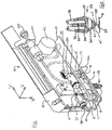
Fig.1 is an isometric front view of a test cartridge according to the invention, with cover open; -
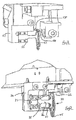
Fig. 2 is an enlarged elevation from one side of the jaw arrangement ofFig. 1 ; -
Fig. 3 is an enlarged elevation from one side of an alternative jaw arrangement;Fig. 4 is an enlarged side elevation of the jaw ofFig. 3 showing the attached cantilever beam. -
Fig. 5 is an enlarged front elevation of the jaw ofFig. 3 . -
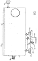
Fig. 6 is a front elevation of the cartridge ofFig. 1 , with cover closed. -
Fig. 7 is a front elevation of a cartridge corresponding toFig. 3 , with cover closed. -
Fig. 8 is an enlarged front elevation of the jaw ofFig. 1 . -
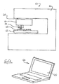
Fig. 9 illustrates schematically a testing apparatus. - With reference to
Figs. 1 and6 atest cartridge 10 is adapted for mounting in a test machine having sufficient axes of movement to move the cartridge in a desired direction with respect to a test piece. The test piece may for example be mounted on a fixed base plate, and the cartridge be movable about X and Y axes to position gripping jaws at a test location, and in the Z axis to allow the jaws to approach and grip a test ball, and to apply a pull test. An example of a prior art test machine is the Series 4000 machine sold by Dage Precision Industries of Aylesbury, England. - Alternatively the test piece may be movable on an X-Y table, and the test cartridge be confined to Z axis movement. Typical X, Y and Z axes are illustrated.
- The
cartridge 10 comprises a chassis 11 having a hingedcover 12 to conceal and protect sensitive components; the cover is shown in the open condition inFig. 1 . - Mounted on the chassis is a frame having two
uprights 15. Inboard of each upright 15 and passing through anaperture 16 in frame 11, are generallyupright legs 17. Thelegs 17 are pivoted with respect to theuprights 15 bypins 18, and are connected at pivot pins 19 by a pneumatic ram 20, situated between the uprights 15. - As an alternative to the pneumatic ram 20, the device could alternatively use other means such as an electric motor or an electro-magnet.
- The lower ends of the
legs 17 protrude through alower flange 21 of the chassis 11 and each is coupled to atension member 22 which acts on a respective arm of a jaw 23 (Fig. 6 ). - The
jaw 23 is more clearly illustrated inFigs. 2 and8 and may comprises a unitary generally 'H' shaped symmetrical metal component having a central mountinglimb 24 extending from the upper side of the cross piece 25. Eacharm 26 is a mirror image, and has alower portion 27 which approaches the centre-line. Theselower portions 27 define between them asmall gap 28 and suitable shaped recesses (not shown) adapted to grip a protruding ball deposit 29 on asubstrate 31.US Patent Number 6,237,422 shows an example of such a recess. - The
upper portions 32 of thearms 26 are coupled torespective tension members 22, as illustrated. The tension members may be cylindrical section wires, or may be of flat rectangular section. The joining method is not important, provided it is secure; adhesive or soldering are suitable, but preferably a mechanical hook and/or a mechanical clamp are used. As illustrated mechanical clamps are provided at the outboard ends, and may be tightened when the jaw is in the rest condition. - The mounting
limb 24 has threeholes 33, two of which are for accurate generally sliding location onto spigot pins, and the third of which is for receiving a retention screw; the screw is typically placed through the centremost hole. - The mass of the jaw is designed to be small, and can be further reduced by the use of holes in the
arms 26. - A
substantial mounting block 34 is secured to the chassis and has mounted thereon a cantilever strain gauge element 35 (Fig. 2 ) having acentral beam 36, and upper andlower arms 37 which have suitable strain gauges mounted thereon.US Patent 6,301,971 discusses the use of strain gauges on members such asarms 37 in test equipment of this type. One type of strain gauge comprises an insulative flexible backing supporting a metallic foil pattern. As the foil is deformed due to stress on thelower arm 37, for example, the electric resistance of the gauge changes. This change in resistance is typically measured using a Wheatstone bridge. The change in resistance can be related to the strain onarm 37 and correlated to the tensile force applied to the solder ball by thejaw 23. Semiconductor strain gauges could also be used. - The
jaw 23 is mounted to the free end of theelement 35 so that the closing direction thereof is substantially orthogonal to the direction of cantilever extension, and both of these directions are substantially orthogonal to the direction of cantilever bending. - It will be appreciated that shortening of the ram 20 by retracting the shaft into pneumatic cylinder of ram 20 will cause the lower ends of
legs 17 to pivot outwardly, applying tension to themembers 22, and thus bending thearms 26 about the narrow cross piece 25 to close thejaw gap 28. - The cross piece 25 is comparatively thin to allow bending of the
arms 26 without exceeding the yield strength thereof. - Attached to one
arm 26 is aflat plate 30 which extends across theother arm 26; this other arm is lightly biased against theplate 30 to allow the jaws to close under friction, and thus with an improved degree of lateral control. More accurate jaw closing is thus achieved. - Also mounted on the chassis are an
air pressure regulator 41 having inlet and outlet connections and ascrew adjuster 40, and a pressure gauge 42 (the face of which is not illustrated). Theregulator 41,gauge 42 and ram 20 are connected to a source of air under pressure by pipework as illustrated. - Resilience of the
jaw 23 determines a natural rest condition of thelegs 17. Thegap 28 may be adjusted bygrub screws 43 acting between theuprights 15 and thelegs 17. Such grub screws are arranged to be adjustable independently, and have suitable lock nuts. Alternatively the grub screws may act at the upper ends of thelegs 17 anduprights 15. - Also provided between the upper ends of the
uprights 15 andadjacent legs 17 are respective coil springs 37. The right spring (as viewed) has relatively fixed ends, but the left screw has one end connected via a screw-threadedadjuster 38. By turning the adjuster, the pre-load applied to one arm of thejaws 23 may be altered, adjusting the closed position. Alternatively the left spring may be adjustable and the right spring non-adjustable; in this case the adjuster is hidden within the cover, when closed. - The
flange 21 has aguard 44 provided thereon, and adapted to swing down from the rest position (illustrated) to an active position below thejaw 23. The guard is preferably arranged to move automatically to the rest position when the cartridge is properly attached to a test machine, but otherwise to be in the active position so as to protect the jaw from contact damage. -
Fig. 6 illustrates a front elevation of thecartridge 10 withlid 12 in the closed condition. Easy access to thepressure regulator 41 is provided, and thegauge 42 is visible through an aperture of the lid. - Typical dimensions of the
cartridge 10 are 240mm x 160mm x 60mm, and thejaw 23 is about 33mm high and about 20mm wide. - The thickness of the jaw is typically about 1mm, and the jaw is preferably formed by photo-etching from 1mm stainless steel gauge plate. The mass of the jaw is around 1.5g.
- The
cartridge beam 35 is preferably of aluminium, and has a mass of around 2.2g. - Typical air pressure is around 1bar to achieve a gripping force at the jaw of around 4.5kg, depending on jaw geometry, solder ball shape, etc.
- The jaw may include tip attachments 45 (
Fig. 8 ) of different material and or section. This permits the jaw to be optimised for wear, and allows machining of suitably spaced jaw cavities. Inserts may be of tool or stainless steel, or may be of carbide if a very fine finish of the cavity is required. -
Figs. 3-5 and 7 illustrate an alternative jaw 51 of much smaller size thanjaw 23, but mountable in a cartridge 50 of standard shape and size. It will be understood that the applied gripping force is reduced, commensurate with the lower bonding force, and that the air ram may be sized accordingly. -
Fig. 5 shows that the jaw is somewhat simplified, and being smaller does not require apertures to reduce the mass thereof. The 'H' section is common, along withremovable tip attachments 52 and a control plate 53. Opposite inwardly facingextensions 54 at the side opposite theattachments 52 limit the stroke of the jaw in the opening direction so as to avoid over-stressing thereof. - The strain gauge element 55, to which the jaw 51 is mounted, comprises a single cantilever arm 56 which is suitably strain gauged to indicate pulling forces exerted by the jaw.
Fig. 3 illustrates the element 55 attached to a mountingblock 57 of the chassis. The range of movement in use is small, so that the pulling load is substantially vertical in use. -
Fig. 3 also illustrates that thetension members 58 may be flat and plate-like. -
Fig. 7 illustrates theguard 44 in the deployed condition, in which the jaw is protected from accidental contact damage. - Use of the apparatus in performing a tensile test is as follows, with additional reference to
Fig. 9 . - A typical tensile test machine 60 comprises a frame 61 having thereon a
platen 62 to which a test sample 63 is securely attached by suitable clamps (not shown). Theplaten 62 is movable in the X and Y directions (left to right as viewed, and in and out of the drawing plane as viewed) under the control of suitable electric motors. A precision positioning system appropriate to a conventional vertical axis milling machine is suitable. - The frame 61 extends over the
platen 62 and includes ahead 68 movable in the Z direction (up and down as viewed) under control of a suitable precision electric motor. Mounted securely on the head is atest cartridge 10. As noted above, the act of mounting the head causes aguard 44 to swing up to expose thejaw 23, 51. - The strain gauged
element 35, 55 to which thejaw 23, 51 is mounted has an electrical output recorded on a suitable apparatus, typically a personal computer 64, and may give a direct visual output via a screen 65 in addition to recording time, displacement and force characteristic for subsequent analysis. - In use the X-Y table is driven to position a chosen solder ball immediately below the
open jaw 23, 51. A suitable vision system may be used, but more preferably an automatic alignment system which may for example be actuated according to a stimulus on the sample, or according to information about the size and spacing of an array of test specimens. - Once vertically aligned, the test cartridge is driven down with jaw open to a predetermined spacing above the substrate of the sample on which the solder balls are formed. At this stage the strain gauge element is unstressed.
- The
jaw 23, 51 is closed about the solder ball by actuation of the ram 20 and without further movement of thetest cartridge 10. The cross piece of the jaw is substantially unaffected by such clamping motion notwithstanding the high clamping force (e.g. 5 kgf) which is imposed. At this stage the strain gauge element remains unstressed and essentially de-coupled from the clamping force. - The tensile test is performed on the sample by vertical upward movement of the test cartridge. Upward movement causes the strain gauged
element 35, 55 to bend and emit an electrical signal proportional to the force imposed. Eventually the bond between the ball deposit and substrate will break, and allow a breaking force to be calculated from the output of the strain gauge(s). - The very low comparative mass of the jaw is de-coupled from the mass of the ram 20 and associated actuation elements, so that the measured force is more closely representative of the actual forces in the bonding plane.
- The apparatus of
Fig. 9 may be modified to perform an impact test whereby the tensile test is performed at high speed (at a high rate of increase of strain). Such a test may comprise rapid upward movement of the test cartridge, and platen, and sudden stopping of the platen, as described in International publicationWO/2005/093436 . - The speed of testing is selected to simulate the impact forces which may be experienced by equipment to which is fitted electrical components equivalent to the test sample. Such speeds may for example simulate the impact force of a mobile phone when dropped upon the ground, and are to some extent influenced by the mounting arrangements for electrical components within equipment, and any shock absorbing properties thereof. Suitable testing speeds are selectable in a range from virtually zero up to 1000 mm/s. During the test described above the jaw is clamped to the sample and is effectively part of the mass thereof.
- By minimizing the mass of the jaw to the greatest extent, and isolating the jaw from the jaw closing apparatus, the inertial effect of the jaw, which in practice tends to increase resistance to movement, is minimized. The apparatus of the invention thus provides for tensile testing which more closely simulates actual failure modes.
- A unitary jaw is particularly advantageous because a pivot axis (as in scissors) is not provided, and thus there is no play, friction or lost motion. Furthermore the risk of seizure is eliminated. Yet another advantage is that a unitary jaw is inherently resilient and thus requires no return spring - simplicity and low mass can be assured. Finally, a unitary jaw has a fixed rest condition when unstressed, and thus no setting or backstops are required to maintain a predetermined jaw opening. These are advantages which are realised for all testing speeds.
- It is intended to be understood that this invention is not limited to the embodiments described herein and that variants, obvious to those skilled in the art, can be made which are within the scope of the apparatus claims appended hereto. For example, the jaw of the invention is illustrated in a vertical orientation, pulling upwardly, but other pulling orientations are possible.
Claims (4)
- A tensile test machine (60) for testing miniature metallic bonds of electrical equipment, the machine (60) having a jaw (23, 51) for gripping a deposit on a substrate, the jaw (23, 51) having two rigid members, each of the rigid members (26) having a upper end and an oppositely disposed lower end, characterised in that the jaw (23, 51) has a central member (25) connecting the two rigid members, and the machine (60) has a beam which Is supported on said machine, the jaw (23, 51) being attached to the beam, the beam supporting force measurement elements and the machine supporting an actuating mechanism and comprising tension elements (22), the upper ends of the rigid members (26) being attached by said tension elements (22) to said actuating mechanism, said actuating mechanism being suited to apply a tension force to said tension elements to pull said upper ends of said rigid members (26) away from one another, said movement of said upper ends away from one another causing said lower ends to move towards one another to grip said deposit.
- A machine according to claim 1, and further including a platen for mounting of a substrate having a deposit to be gripped in use by said jaw (23, 51), said beam being movable relatively In a first direction towards and away from said platen to position said jaw (23, 51) for gripping.
- A machine according to claim 2, wherein said platen Is relatively movable in a plane perpendicular to said direction to position said jaw (23, 51) over a deposit to be tested.
- A machine according to claim 2 or claim 3, and comprising a machine frame on which said platen is relatively movable in said plane, and on which said beam is relatively movable in said direction.
Applications Claiming Priority (2)
| Application Number | Priority Date | Filing Date | Title |
|---|---|---|---|
| GBGB0613205.4A GB0613205D0 (en) | 2006-07-03 | 2006-07-03 | High speed test cartridge |
| EP07733443.1A EP2035804B1 (en) | 2006-07-03 | 2007-07-03 | Tensile test device for testing deposits on electronic substrates |
Related Parent Applications (1)
| Application Number | Title | Priority Date | Filing Date |
|---|---|---|---|
| EP07733443.1A Division EP2035804B1 (en) | 2006-07-03 | 2007-07-03 | Tensile test device for testing deposits on electronic substrates |
Publications (2)
| Publication Number | Publication Date |
|---|---|
| EP2728335A1 EP2728335A1 (en) | 2014-05-07 |
| EP2728335B1 true EP2728335B1 (en) | 2016-03-23 |
Family
ID=36888555
Family Applications (2)
| Application Number | Title | Priority Date | Filing Date |
|---|---|---|---|
| EP14153545.0A Ceased EP2728335B1 (en) | 2006-07-03 | 2007-07-03 | Tensile test device for testing deposits on electronic substrates |
| EP07733443.1A Ceased EP2035804B1 (en) | 2006-07-03 | 2007-07-03 | Tensile test device for testing deposits on electronic substrates |
Family Applications After (1)
| Application Number | Title | Priority Date | Filing Date |
|---|---|---|---|
| EP07733443.1A Ceased EP2035804B1 (en) | 2006-07-03 | 2007-07-03 | Tensile test device for testing deposits on electronic substrates |
Country Status (7)
| Country | Link |
|---|---|
| US (2) | US8100021B2 (en) |
| EP (2) | EP2728335B1 (en) |
| JP (2) | JP5158887B2 (en) |
| KR (1) | KR101370297B1 (en) |
| CN (2) | CN102879259B (en) |
| GB (1) | GB0613205D0 (en) |
| WO (1) | WO2008003948A1 (en) |
Families Citing this family (23)
| Publication number | Priority date | Publication date | Assignee | Title |
|---|---|---|---|---|
| GB0604700D0 (en) * | 2006-03-08 | 2006-04-19 | Dage Prec Ind Ltd | Shear testing of metallic balls of electrical components |
| GB0613205D0 (en) * | 2006-07-03 | 2006-08-09 | Dage Prec Ind Ltd | High speed test cartridge |
| US7810374B2 (en) | 2007-12-03 | 2010-10-12 | The Hong Kong University Of Science And Technology | Single solder ball impact tester |
| EP2363702B1 (en) * | 2010-03-05 | 2016-09-28 | Nordson Corporation | Bond strength tester with switchable backlash control |
| US8534136B2 (en) * | 2010-03-31 | 2013-09-17 | Flextronics Ap, Llc. | Pin soldering for printed circuit board failure testing |
| CN102735540A (en) * | 2011-04-01 | 2012-10-17 | 亚旭电子科技(江苏)有限公司 | Tensile test device |
| CN102494949A (en) * | 2011-10-20 | 2012-06-13 | 华中科技大学 | Strength testing device for welded ball |
| US9212981B2 (en) * | 2012-12-07 | 2015-12-15 | Purdue Research Foundation | Feedback system and method for assessing fixation and stability of implantable leads |
| EP3165895B1 (en) * | 2013-07-03 | 2019-05-08 | Nordson Corp | Cartridge for a bond testing machine comprising a plurality of test tools |
| US9903781B2 (en) | 2014-03-28 | 2018-02-27 | United Technologies Corporation | Material testing apparatus and method |
| CN103900807B (en) * | 2014-04-01 | 2016-04-06 | 苏州博众精工科技有限公司 | A kind of pull-out test mechanism |
| US9964563B1 (en) | 2014-07-18 | 2018-05-08 | Flextronics Ap, Llc | Method and apparatus for ICT fixture probe cleaning |
| GB201413225D0 (en) * | 2014-07-25 | 2014-09-10 | Sykes Robert J And Xyztec Bv | Solder cleaning system |
| CN105067518B (en) * | 2015-09-18 | 2017-11-03 | 吉林大学 | A kind of method that bonding agent adhesive property for flat substrates is tested |
| NL2015919B1 (en) | 2015-12-07 | 2017-06-28 | Xyztec B V | A method for determining a strength of a bond and/or a material as well as a bond tester apparatus. |
| CN105738279A (en) * | 2016-03-01 | 2016-07-06 | 银邦金属复合材料股份有限公司 | Test sample drawing die and test sample drawing method employing same |
| CN106442313B (en) * | 2016-08-23 | 2019-04-02 | 北京时代民芯科技有限公司 | A kind of lead integrity tester |
| US10416053B2 (en) * | 2017-01-23 | 2019-09-17 | Northwestern University | Grips for a linear fracture testing machine and method of designing same |
| GB201713169D0 (en) * | 2017-08-16 | 2017-09-27 | Nordson Corp | Bond test apparatus and method |
| EP3885844A1 (en) | 2020-03-27 | 2021-09-29 | Nivarox-FAR S.A. | Clamp for a timepiece setting machine |
| CN114858884A (en) * | 2022-05-07 | 2022-08-05 | 天津北洋精工技术有限公司 | Chuck structure of general acidimeter |
| WO2024044103A1 (en) * | 2022-08-24 | 2024-02-29 | Acoustic Wells, Inc. | Systems and methods for measuring wire rope tension |
| CN118392782B (en) * | 2024-06-28 | 2024-09-13 | 江苏铭丰电子材料科技有限公司 | Anti-stripping detection device for copper foil production |
Family Cites Families (26)
| Publication number | Priority date | Publication date | Assignee | Title |
|---|---|---|---|---|
| US3170322A (en) * | 1962-06-05 | 1965-02-23 | Instron Corp | Grip |
| US3698249A (en) * | 1970-08-03 | 1972-10-17 | Umc Electronics Co | Fluid pressure monitoring system |
| US4198870A (en) * | 1978-11-09 | 1980-04-22 | Terra Tek, Inc. | Constant point of load application fracture specimen loading machine |
| US4292852A (en) * | 1980-01-30 | 1981-10-06 | General Electric Company | Method and apparatus for physically testing the integrity of the connection between an electrode assembly and a terminal conductor of an electrochemical cell |
| JPS6126156U (en) * | 1984-07-20 | 1986-02-17 | 富士電機株式会社 | Bonding strength measuring device |
| US4662229A (en) * | 1985-08-26 | 1987-05-05 | Curtis John M | Grip assembly |
| JPS6332786U (en) * | 1986-08-19 | 1988-03-02 | ||
| JP2509834B2 (en) * | 1991-07-31 | 1996-06-26 | 株式会社オリエンテック | Load cell structure for low load |
| JPH05195958A (en) * | 1992-01-21 | 1993-08-06 | Yaskawa Electric Corp | Piezoelectric pump |
| JPH05305574A (en) * | 1992-04-15 | 1993-11-19 | Nec Corp | Piezoelectric cramping mechanism |
| JPH0584126U (en) * | 1992-04-20 | 1993-11-12 | 住友電装株式会社 | Clamp for wire harness |
| JP2973832B2 (en) * | 1994-10-07 | 1999-11-08 | 株式会社デンソー | Test method and test apparatus for semiconductor bump electrode |
| JP3328473B2 (en) * | 1995-08-03 | 2002-09-24 | ワイケイケイニューマックス株式会社 | Snap member removal force measuring device |
| GB9724458D0 (en) | 1997-11-20 | 1998-01-14 | Dage Precision Ind Ltd | Test apparatus |
| US6237422B1 (en) * | 1997-12-13 | 2001-05-29 | Dage Precision Industries Ltd. | Apparatus and method for testing strength of electrical bond sites on semiconductor devices |
| JPH11274248A (en) * | 1998-01-19 | 1999-10-08 | Resuka:Kk | Bonding strength testing device |
| JP3811647B2 (en) * | 2001-04-06 | 2006-08-23 | Ykkスナップファスナー株式会社 | Device and method for measuring fastener member removal force |
| CA2372551C (en) * | 2002-02-18 | 2006-07-04 | Ibm Canada Limited-Ibm Canada Limitee | Improved structure and method for testing bond strength and/or removing integrated circuit devices bonded to substrates |
| JP4268127B2 (en) * | 2002-05-30 | 2009-05-27 | Ykk株式会社 | Constraint device and snap member removal force measuring device |
| JP4380366B2 (en) * | 2004-03-03 | 2009-12-09 | 富士ゼロックス株式会社 | Protective member |
| GB0406434D0 (en) * | 2004-03-22 | 2004-04-28 | Dage Prec Ind Ltd | High speed pull test device |
| JP4337595B2 (en) * | 2004-03-25 | 2009-09-30 | 株式会社島津製作所 | Load cell |
| GB0411057D0 (en) * | 2004-05-18 | 2004-06-23 | Dage Prec Ind Ltd | Test apparatus |
| US7905152B2 (en) * | 2006-02-17 | 2011-03-15 | Nordson Corporation | Shear test apparatus and method |
| GB0604700D0 (en) * | 2006-03-08 | 2006-04-19 | Dage Prec Ind Ltd | Shear testing of metallic balls of electrical components |
| GB0613205D0 (en) * | 2006-07-03 | 2006-08-09 | Dage Prec Ind Ltd | High speed test cartridge |
-
2006
- 2006-07-03 GB GBGB0613205.4A patent/GB0613205D0/en not_active Ceased
-
2007
- 2007-07-03 EP EP14153545.0A patent/EP2728335B1/en not_active Ceased
- 2007-07-03 WO PCT/GB2007/002474 patent/WO2008003948A1/en active Application Filing
- 2007-07-03 EP EP07733443.1A patent/EP2035804B1/en not_active Ceased
- 2007-07-03 JP JP2009517418A patent/JP5158887B2/en not_active Expired - Fee Related
- 2007-07-03 KR KR1020087030680A patent/KR101370297B1/en active IP Right Grant
- 2007-07-03 US US12/303,488 patent/US8100021B2/en not_active Expired - Fee Related
- 2007-07-03 CN CN201210321258.2A patent/CN102879259B/en not_active Expired - Fee Related
- 2007-07-03 CN CN2007800250700A patent/CN101484788B/en not_active Expired - Fee Related
-
2011
- 2011-12-15 US US13/326,737 patent/US8646337B2/en not_active Expired - Fee Related
-
2012
- 2012-06-13 JP JP2012133538A patent/JP5563019B2/en not_active Expired - Fee Related
Also Published As
| Publication number | Publication date |
|---|---|
| US8100021B2 (en) | 2012-01-24 |
| CN101484788B (en) | 2012-10-10 |
| EP2035804A1 (en) | 2009-03-18 |
| KR20090035485A (en) | 2009-04-09 |
| KR101370297B1 (en) | 2014-03-05 |
| CN101484788A (en) | 2009-07-15 |
| CN102879259B (en) | 2015-04-29 |
| JP2009543034A (en) | 2009-12-03 |
| WO2008003948A1 (en) | 2008-01-10 |
| EP2728335A1 (en) | 2014-05-07 |
| JP2012168201A (en) | 2012-09-06 |
| EP2035804B1 (en) | 2014-03-05 |
| US8646337B2 (en) | 2014-02-11 |
| CN102879259A (en) | 2013-01-16 |
| US20120204654A1 (en) | 2012-08-16 |
| GB0613205D0 (en) | 2006-08-09 |
| JP5563019B2 (en) | 2014-07-30 |
| JP5158887B2 (en) | 2013-03-06 |
| US20090301216A1 (en) | 2009-12-10 |
Similar Documents
| Publication | Publication Date | Title |
|---|---|---|
| EP2728335B1 (en) | Tensile test device for testing deposits on electronic substrates | |
| EP2363701B1 (en) | Improved clamping mechanism for shear testing apparatus | |
| US20080141783A1 (en) | Micro-Impact Testing Apparatus | |
| JP5751867B2 (en) | Bond strength testing device with switchable backlash control device | |
| KR100903560B1 (en) | Apparatus for providing impact test | |
| US20090019941A1 (en) | Pull test calibration device and method | |
| EP2570790B1 (en) | Shear test method | |
| US20100116063A1 (en) | Shear test apparatus and method | |
| US5741976A (en) | Apparatus for the single-axis examination of micro-tension samples | |
| US9919374B2 (en) | Robotic gripper sensor | |
| US20020170360A1 (en) | Apparatus for characterizing material properties and method | |
| JP3592992B2 (en) | Fretting fatigue test apparatus and fretting fatigue estimation method | |
| US7284445B2 (en) | Strain waveform control apparatus, strain waveform regulating member, strain waveform control method by using strain waveform control apparatus, and strain waveform control program | |
| US20240272052A1 (en) | Device and method for the thermo-electro-mechanical characterization of microscale wires |
Legal Events
| Date | Code | Title | Description |
|---|---|---|---|
| PUAI | Public reference made under article 153(3) epc to a published international application that has entered the european phase |
Free format text: ORIGINAL CODE: 0009012 |
|
| 17P | Request for examination filed |
Effective date: 20140131 |
|
| AC | Divisional application: reference to earlier application |
Ref document number: 2035804 Country of ref document: EP Kind code of ref document: P |
|
| AK | Designated contracting states |
Kind code of ref document: A1 Designated state(s): DE GB NL |
|
| 17P | Request for examination filed |
Effective date: 20141107 |
|
| RBV | Designated contracting states (corrected) |
Designated state(s): DE GB NL |
|
| 17Q | First examination report despatched |
Effective date: 20150210 |
|
| GRAP | Despatch of communication of intention to grant a patent |
Free format text: ORIGINAL CODE: EPIDOSNIGR1 |
|
| INTG | Intention to grant announced |
Effective date: 20150924 |
|
| RAP1 | Party data changed (applicant data changed or rights of an application transferred) |
Owner name: DAGE PRECISION INDUSTRIES LTD. |
|
| GRAS | Grant fee paid |
Free format text: ORIGINAL CODE: EPIDOSNIGR3 |
|
| GRAA | (expected) grant |
Free format text: ORIGINAL CODE: 0009210 |
|
| AC | Divisional application: reference to earlier application |
Ref document number: 2035804 Country of ref document: EP Kind code of ref document: P |
|
| AK | Designated contracting states |
Kind code of ref document: B1 Designated state(s): DE GB NL |
|
| REG | Reference to a national code |
Ref country code: GB Ref legal event code: FG4D |
|
| REG | Reference to a national code |
Ref country code: DE Ref legal event code: R096 Ref document number: 602007045500 Country of ref document: DE |
|
| REG | Reference to a national code |
Ref country code: NL Ref legal event code: FP |
|
| REG | Reference to a national code |
Ref country code: DE Ref legal event code: R097 Ref document number: 602007045500 Country of ref document: DE |
|
| PLBE | No opposition filed within time limit |
Free format text: ORIGINAL CODE: 0009261 |
|
| STAA | Information on the status of an ep patent application or granted ep patent |
Free format text: STATUS: NO OPPOSITION FILED WITHIN TIME LIMIT |
|
| 26N | No opposition filed |
Effective date: 20170102 |
|
| PGFP | Annual fee paid to national office [announced via postgrant information from national office to epo] |
Ref country code: DE Payment date: 20190719 Year of fee payment: 13 |
|
| PGFP | Annual fee paid to national office [announced via postgrant information from national office to epo] |
Ref country code: GB Payment date: 20190719 Year of fee payment: 13 |
|
| REG | Reference to a national code |
Ref country code: DE Ref legal event code: R119 Ref document number: 602007045500 Country of ref document: DE |
|
| GBPC | Gb: european patent ceased through non-payment of renewal fee |
Effective date: 20200703 |
|
| PG25 | Lapsed in a contracting state [announced via postgrant information from national office to epo] |
Ref country code: GB Free format text: LAPSE BECAUSE OF NON-PAYMENT OF DUE FEES Effective date: 20200703 |
|
| PG25 | Lapsed in a contracting state [announced via postgrant information from national office to epo] |
Ref country code: DE Free format text: LAPSE BECAUSE OF NON-PAYMENT OF DUE FEES Effective date: 20210202 |
|
| PGFP | Annual fee paid to national office [announced via postgrant information from national office to epo] |
Ref country code: NL Payment date: 20210721 Year of fee payment: 15 |
|
| REG | Reference to a national code |
Ref country code: NL Ref legal event code: MM Effective date: 20220801 |
|
| PG25 | Lapsed in a contracting state [announced via postgrant information from national office to epo] |
Ref country code: NL Free format text: LAPSE BECAUSE OF NON-PAYMENT OF DUE FEES Effective date: 20220801 |