EP2728242A1 - Pressure storage system and method for operating the same - Google Patents
Pressure storage system and method for operating the same Download PDFInfo
- Publication number
- EP2728242A1 EP2728242A1 EP20120191303 EP12191303A EP2728242A1 EP 2728242 A1 EP2728242 A1 EP 2728242A1 EP 20120191303 EP20120191303 EP 20120191303 EP 12191303 A EP12191303 A EP 12191303A EP 2728242 A1 EP2728242 A1 EP 2728242A1
- Authority
- EP
- European Patent Office
- Prior art keywords
- pressure
- valve
- check valve
- piston
- accumulator
- Prior art date
- Legal status (The legal status is an assumption and is not a legal conclusion. Google has not performed a legal analysis and makes no representation as to the accuracy of the status listed.)
- Granted
Links
- 238000000034 method Methods 0.000 title claims abstract description 14
- 238000003860 storage Methods 0.000 title claims description 90
- 238000007789 sealing Methods 0.000 claims description 45
- 230000004888 barrier function Effects 0.000 claims description 28
- 238000011144 upstream manufacturing Methods 0.000 claims description 17
- 239000000945 filler Substances 0.000 claims description 12
- 230000007423 decrease Effects 0.000 claims description 6
- 230000000694 effects Effects 0.000 claims description 5
- 238000010079 rubber tapping Methods 0.000 claims 1
- 239000012530 fluid Substances 0.000 abstract description 2
- 239000007789 gas Substances 0.000 description 51
- 230000000903 blocking effect Effects 0.000 description 16
- VNWKTOKETHGBQD-UHFFFAOYSA-N methane Chemical compound C VNWKTOKETHGBQD-UHFFFAOYSA-N 0.000 description 14
- 230000015654 memory Effects 0.000 description 12
- 238000000605 extraction Methods 0.000 description 9
- 230000008901 benefit Effects 0.000 description 6
- 238000005429 filling process Methods 0.000 description 6
- 238000009434 installation Methods 0.000 description 6
- 239000003345 natural gas Substances 0.000 description 6
- 239000000446 fuel Substances 0.000 description 5
- 238000010276 construction Methods 0.000 description 4
- 238000013461 design Methods 0.000 description 4
- 239000000463 material Substances 0.000 description 4
- 230000000712 assembly Effects 0.000 description 3
- 238000000429 assembly Methods 0.000 description 3
- 238000009530 blood pressure measurement Methods 0.000 description 3
- 230000006870 function Effects 0.000 description 3
- 229910052739 hydrogen Inorganic materials 0.000 description 3
- 239000001257 hydrogen Substances 0.000 description 3
- 230000010354 integration Effects 0.000 description 3
- 238000005070 sampling Methods 0.000 description 3
- 125000006850 spacer group Chemical group 0.000 description 3
- 238000004891 communication Methods 0.000 description 2
- 230000006378 damage Effects 0.000 description 2
- 238000010586 diagram Methods 0.000 description 2
- 238000009826 distribution Methods 0.000 description 2
- 150000002431 hydrogen Chemical class 0.000 description 2
- 239000007788 liquid Substances 0.000 description 2
- 238000004519 manufacturing process Methods 0.000 description 2
- 238000012544 monitoring process Methods 0.000 description 2
- UFHFLCQGNIYNRP-UHFFFAOYSA-N Hydrogen Chemical compound [H][H] UFHFLCQGNIYNRP-UHFFFAOYSA-N 0.000 description 1
- 239000004696 Poly ether ether ketone Substances 0.000 description 1
- 229910000831 Steel Inorganic materials 0.000 description 1
- PNEYBMLMFCGWSK-UHFFFAOYSA-N aluminium oxide Inorganic materials [O-2].[O-2].[O-2].[Al+3].[Al+3] PNEYBMLMFCGWSK-UHFFFAOYSA-N 0.000 description 1
- 239000011324 bead Substances 0.000 description 1
- 230000006399 behavior Effects 0.000 description 1
- JUPQTSLXMOCDHR-UHFFFAOYSA-N benzene-1,4-diol;bis(4-fluorophenyl)methanone Chemical compound OC1=CC=C(O)C=C1.C1=CC(F)=CC=C1C(=O)C1=CC=C(F)C=C1 JUPQTSLXMOCDHR-UHFFFAOYSA-N 0.000 description 1
- 229910010293 ceramic material Inorganic materials 0.000 description 1
- 230000000295 complement effect Effects 0.000 description 1
- 230000001419 dependent effect Effects 0.000 description 1
- 238000011161 development Methods 0.000 description 1
- 230000018109 developmental process Effects 0.000 description 1
- 210000003746 feather Anatomy 0.000 description 1
- 238000005259 measurement Methods 0.000 description 1
- 230000007246 mechanism Effects 0.000 description 1
- 229910052751 metal Inorganic materials 0.000 description 1
- 239000002184 metal Substances 0.000 description 1
- 150000002739 metals Chemical class 0.000 description 1
- 239000000203 mixture Substances 0.000 description 1
- 238000012986 modification Methods 0.000 description 1
- 230000004048 modification Effects 0.000 description 1
- 238000012806 monitoring device Methods 0.000 description 1
- 238000011017 operating method Methods 0.000 description 1
- 238000013021 overheating Methods 0.000 description 1
- 239000004033 plastic Substances 0.000 description 1
- 229920003023 plastic Polymers 0.000 description 1
- 229920002530 polyetherether ketone Polymers 0.000 description 1
- 230000008569 process Effects 0.000 description 1
- 230000009467 reduction Effects 0.000 description 1
- HBMJWWWQQXIZIP-UHFFFAOYSA-N silicon carbide Chemical compound [Si+]#[C-] HBMJWWWQQXIZIP-UHFFFAOYSA-N 0.000 description 1
- 229910010271 silicon carbide Inorganic materials 0.000 description 1
- 239000010959 steel Substances 0.000 description 1
- 238000012549 training Methods 0.000 description 1
- 230000007704 transition Effects 0.000 description 1
- 238000009423 ventilation Methods 0.000 description 1
- XLYOFNOQVPJJNP-UHFFFAOYSA-N water Substances O XLYOFNOQVPJJNP-UHFFFAOYSA-N 0.000 description 1
Images


Classifications
-
- F—MECHANICAL ENGINEERING; LIGHTING; HEATING; WEAPONS; BLASTING
- F15—FLUID-PRESSURE ACTUATORS; HYDRAULICS OR PNEUMATICS IN GENERAL
- F15B—SYSTEMS ACTING BY MEANS OF FLUIDS IN GENERAL; FLUID-PRESSURE ACTUATORS, e.g. SERVOMOTORS; DETAILS OF FLUID-PRESSURE SYSTEMS, NOT OTHERWISE PROVIDED FOR
- F15B1/00—Installations or systems with accumulators; Supply reservoir or sump assemblies
- F15B1/02—Installations or systems with accumulators
- F15B1/04—Accumulators
-
- F—MECHANICAL ENGINEERING; LIGHTING; HEATING; WEAPONS; BLASTING
- F17—STORING OR DISTRIBUTING GASES OR LIQUIDS
- F17C—VESSELS FOR CONTAINING OR STORING COMPRESSED, LIQUEFIED OR SOLIDIFIED GASES; FIXED-CAPACITY GAS-HOLDERS; FILLING VESSELS WITH, OR DISCHARGING FROM VESSELS, COMPRESSED, LIQUEFIED, OR SOLIDIFIED GASES
- F17C13/00—Details of vessels or of the filling or discharging of vessels
- F17C13/04—Arrangement or mounting of valves
-
- F—MECHANICAL ENGINEERING; LIGHTING; HEATING; WEAPONS; BLASTING
- F17—STORING OR DISTRIBUTING GASES OR LIQUIDS
- F17C—VESSELS FOR CONTAINING OR STORING COMPRESSED, LIQUEFIED OR SOLIDIFIED GASES; FIXED-CAPACITY GAS-HOLDERS; FILLING VESSELS WITH, OR DISCHARGING FROM VESSELS, COMPRESSED, LIQUEFIED, OR SOLIDIFIED GASES
- F17C5/00—Methods or apparatus for filling containers with liquefied, solidified, or compressed gases under pressures
- F17C5/06—Methods or apparatus for filling containers with liquefied, solidified, or compressed gases under pressures for filling with compressed gases
-
- F—MECHANICAL ENGINEERING; LIGHTING; HEATING; WEAPONS; BLASTING
- F17—STORING OR DISTRIBUTING GASES OR LIQUIDS
- F17C—VESSELS FOR CONTAINING OR STORING COMPRESSED, LIQUEFIED OR SOLIDIFIED GASES; FIXED-CAPACITY GAS-HOLDERS; FILLING VESSELS WITH, OR DISCHARGING FROM VESSELS, COMPRESSED, LIQUEFIED, OR SOLIDIFIED GASES
- F17C13/00—Details of vessels or of the filling or discharging of vessels
- F17C13/02—Special adaptations of indicating, measuring, or monitoring equipment
-
- F—MECHANICAL ENGINEERING; LIGHTING; HEATING; WEAPONS; BLASTING
- F17—STORING OR DISTRIBUTING GASES OR LIQUIDS
- F17C—VESSELS FOR CONTAINING OR STORING COMPRESSED, LIQUEFIED OR SOLIDIFIED GASES; FIXED-CAPACITY GAS-HOLDERS; FILLING VESSELS WITH, OR DISCHARGING FROM VESSELS, COMPRESSED, LIQUEFIED, OR SOLIDIFIED GASES
- F17C2205/00—Vessel construction, in particular mounting arrangements, attachments or identifications means
- F17C2205/01—Mounting arrangements
- F17C2205/0123—Mounting arrangements characterised by number of vessels
- F17C2205/013—Two or more vessels
- F17C2205/0134—Two or more vessels characterised by the presence of fluid connection between vessels
-
- F—MECHANICAL ENGINEERING; LIGHTING; HEATING; WEAPONS; BLASTING
- F17—STORING OR DISTRIBUTING GASES OR LIQUIDS
- F17C—VESSELS FOR CONTAINING OR STORING COMPRESSED, LIQUEFIED OR SOLIDIFIED GASES; FIXED-CAPACITY GAS-HOLDERS; FILLING VESSELS WITH, OR DISCHARGING FROM VESSELS, COMPRESSED, LIQUEFIED, OR SOLIDIFIED GASES
- F17C2205/00—Vessel construction, in particular mounting arrangements, attachments or identifications means
- F17C2205/03—Fluid connections, filters, valves, closure means or other attachments
- F17C2205/0302—Fittings, valves, filters, or components in connection with the gas storage device
- F17C2205/0323—Valves
- F17C2205/0335—Check-valves or non-return valves
-
- F—MECHANICAL ENGINEERING; LIGHTING; HEATING; WEAPONS; BLASTING
- F17—STORING OR DISTRIBUTING GASES OR LIQUIDS
- F17C—VESSELS FOR CONTAINING OR STORING COMPRESSED, LIQUEFIED OR SOLIDIFIED GASES; FIXED-CAPACITY GAS-HOLDERS; FILLING VESSELS WITH, OR DISCHARGING FROM VESSELS, COMPRESSED, LIQUEFIED, OR SOLIDIFIED GASES
- F17C2205/00—Vessel construction, in particular mounting arrangements, attachments or identifications means
- F17C2205/03—Fluid connections, filters, valves, closure means or other attachments
- F17C2205/0302—Fittings, valves, filters, or components in connection with the gas storage device
- F17C2205/037—Quick connecting means, e.g. couplings
-
- F—MECHANICAL ENGINEERING; LIGHTING; HEATING; WEAPONS; BLASTING
- F17—STORING OR DISTRIBUTING GASES OR LIQUIDS
- F17C—VESSELS FOR CONTAINING OR STORING COMPRESSED, LIQUEFIED OR SOLIDIFIED GASES; FIXED-CAPACITY GAS-HOLDERS; FILLING VESSELS WITH, OR DISCHARGING FROM VESSELS, COMPRESSED, LIQUEFIED, OR SOLIDIFIED GASES
- F17C2221/00—Handled fluid, in particular type of fluid
- F17C2221/01—Pure fluids
- F17C2221/012—Hydrogen
-
- F—MECHANICAL ENGINEERING; LIGHTING; HEATING; WEAPONS; BLASTING
- F17—STORING OR DISTRIBUTING GASES OR LIQUIDS
- F17C—VESSELS FOR CONTAINING OR STORING COMPRESSED, LIQUEFIED OR SOLIDIFIED GASES; FIXED-CAPACITY GAS-HOLDERS; FILLING VESSELS WITH, OR DISCHARGING FROM VESSELS, COMPRESSED, LIQUEFIED, OR SOLIDIFIED GASES
- F17C2221/00—Handled fluid, in particular type of fluid
- F17C2221/03—Mixtures
- F17C2221/032—Hydrocarbons
- F17C2221/033—Methane, e.g. natural gas, CNG, LNG, GNL, GNC, PLNG
-
- F—MECHANICAL ENGINEERING; LIGHTING; HEATING; WEAPONS; BLASTING
- F17—STORING OR DISTRIBUTING GASES OR LIQUIDS
- F17C—VESSELS FOR CONTAINING OR STORING COMPRESSED, LIQUEFIED OR SOLIDIFIED GASES; FIXED-CAPACITY GAS-HOLDERS; FILLING VESSELS WITH, OR DISCHARGING FROM VESSELS, COMPRESSED, LIQUEFIED, OR SOLIDIFIED GASES
- F17C2221/00—Handled fluid, in particular type of fluid
- F17C2221/03—Mixtures
- F17C2221/032—Hydrocarbons
- F17C2221/035—Propane butane, e.g. LPG, GPL
-
- F—MECHANICAL ENGINEERING; LIGHTING; HEATING; WEAPONS; BLASTING
- F17—STORING OR DISTRIBUTING GASES OR LIQUIDS
- F17C—VESSELS FOR CONTAINING OR STORING COMPRESSED, LIQUEFIED OR SOLIDIFIED GASES; FIXED-CAPACITY GAS-HOLDERS; FILLING VESSELS WITH, OR DISCHARGING FROM VESSELS, COMPRESSED, LIQUEFIED, OR SOLIDIFIED GASES
- F17C2223/00—Handled fluid before transfer, i.e. state of fluid when stored in the vessel or before transfer from the vessel
- F17C2223/01—Handled fluid before transfer, i.e. state of fluid when stored in the vessel or before transfer from the vessel characterised by the phase
- F17C2223/0107—Single phase
- F17C2223/0123—Single phase gaseous, e.g. CNG, GNC
-
- F—MECHANICAL ENGINEERING; LIGHTING; HEATING; WEAPONS; BLASTING
- F17—STORING OR DISTRIBUTING GASES OR LIQUIDS
- F17C—VESSELS FOR CONTAINING OR STORING COMPRESSED, LIQUEFIED OR SOLIDIFIED GASES; FIXED-CAPACITY GAS-HOLDERS; FILLING VESSELS WITH, OR DISCHARGING FROM VESSELS, COMPRESSED, LIQUEFIED, OR SOLIDIFIED GASES
- F17C2223/00—Handled fluid before transfer, i.e. state of fluid when stored in the vessel or before transfer from the vessel
- F17C2223/01—Handled fluid before transfer, i.e. state of fluid when stored in the vessel or before transfer from the vessel characterised by the phase
- F17C2223/0146—Two-phase
- F17C2223/0153—Liquefied gas, e.g. LPG, GPL
- F17C2223/0161—Liquefied gas, e.g. LPG, GPL cryogenic, e.g. LNG, GNL, PLNG
-
- F—MECHANICAL ENGINEERING; LIGHTING; HEATING; WEAPONS; BLASTING
- F17—STORING OR DISTRIBUTING GASES OR LIQUIDS
- F17C—VESSELS FOR CONTAINING OR STORING COMPRESSED, LIQUEFIED OR SOLIDIFIED GASES; FIXED-CAPACITY GAS-HOLDERS; FILLING VESSELS WITH, OR DISCHARGING FROM VESSELS, COMPRESSED, LIQUEFIED, OR SOLIDIFIED GASES
- F17C2223/00—Handled fluid before transfer, i.e. state of fluid when stored in the vessel or before transfer from the vessel
- F17C2223/03—Handled fluid before transfer, i.e. state of fluid when stored in the vessel or before transfer from the vessel characterised by the pressure level
- F17C2223/033—Small pressure, e.g. for liquefied gas
-
- F—MECHANICAL ENGINEERING; LIGHTING; HEATING; WEAPONS; BLASTING
- F17—STORING OR DISTRIBUTING GASES OR LIQUIDS
- F17C—VESSELS FOR CONTAINING OR STORING COMPRESSED, LIQUEFIED OR SOLIDIFIED GASES; FIXED-CAPACITY GAS-HOLDERS; FILLING VESSELS WITH, OR DISCHARGING FROM VESSELS, COMPRESSED, LIQUEFIED, OR SOLIDIFIED GASES
- F17C2223/00—Handled fluid before transfer, i.e. state of fluid when stored in the vessel or before transfer from the vessel
- F17C2223/03—Handled fluid before transfer, i.e. state of fluid when stored in the vessel or before transfer from the vessel characterised by the pressure level
- F17C2223/036—Very high pressure (>80 bar)
-
- F—MECHANICAL ENGINEERING; LIGHTING; HEATING; WEAPONS; BLASTING
- F17—STORING OR DISTRIBUTING GASES OR LIQUIDS
- F17C—VESSELS FOR CONTAINING OR STORING COMPRESSED, LIQUEFIED OR SOLIDIFIED GASES; FIXED-CAPACITY GAS-HOLDERS; FILLING VESSELS WITH, OR DISCHARGING FROM VESSELS, COMPRESSED, LIQUEFIED, OR SOLIDIFIED GASES
- F17C2225/00—Handled fluid after transfer, i.e. state of fluid after transfer from the vessel
- F17C2225/01—Handled fluid after transfer, i.e. state of fluid after transfer from the vessel characterised by the phase
- F17C2225/0107—Single phase
- F17C2225/0123—Single phase gaseous, e.g. CNG, GNC
-
- F—MECHANICAL ENGINEERING; LIGHTING; HEATING; WEAPONS; BLASTING
- F17—STORING OR DISTRIBUTING GASES OR LIQUIDS
- F17C—VESSELS FOR CONTAINING OR STORING COMPRESSED, LIQUEFIED OR SOLIDIFIED GASES; FIXED-CAPACITY GAS-HOLDERS; FILLING VESSELS WITH, OR DISCHARGING FROM VESSELS, COMPRESSED, LIQUEFIED, OR SOLIDIFIED GASES
- F17C2225/00—Handled fluid after transfer, i.e. state of fluid after transfer from the vessel
- F17C2225/03—Handled fluid after transfer, i.e. state of fluid after transfer from the vessel characterised by the pressure level
- F17C2225/036—Very high pressure, i.e. above 80 bars
-
- F—MECHANICAL ENGINEERING; LIGHTING; HEATING; WEAPONS; BLASTING
- F17—STORING OR DISTRIBUTING GASES OR LIQUIDS
- F17C—VESSELS FOR CONTAINING OR STORING COMPRESSED, LIQUEFIED OR SOLIDIFIED GASES; FIXED-CAPACITY GAS-HOLDERS; FILLING VESSELS WITH, OR DISCHARGING FROM VESSELS, COMPRESSED, LIQUEFIED, OR SOLIDIFIED GASES
- F17C2227/00—Transfer of fluids, i.e. method or means for transferring the fluid; Heat exchange with the fluid
- F17C2227/04—Methods for emptying or filling
-
- F—MECHANICAL ENGINEERING; LIGHTING; HEATING; WEAPONS; BLASTING
- F17—STORING OR DISTRIBUTING GASES OR LIQUIDS
- F17C—VESSELS FOR CONTAINING OR STORING COMPRESSED, LIQUEFIED OR SOLIDIFIED GASES; FIXED-CAPACITY GAS-HOLDERS; FILLING VESSELS WITH, OR DISCHARGING FROM VESSELS, COMPRESSED, LIQUEFIED, OR SOLIDIFIED GASES
- F17C2250/00—Accessories; Control means; Indicating, measuring or monitoring of parameters
- F17C2250/01—Intermediate tanks
-
- F—MECHANICAL ENGINEERING; LIGHTING; HEATING; WEAPONS; BLASTING
- F17—STORING OR DISTRIBUTING GASES OR LIQUIDS
- F17C—VESSELS FOR CONTAINING OR STORING COMPRESSED, LIQUEFIED OR SOLIDIFIED GASES; FIXED-CAPACITY GAS-HOLDERS; FILLING VESSELS WITH, OR DISCHARGING FROM VESSELS, COMPRESSED, LIQUEFIED, OR SOLIDIFIED GASES
- F17C2265/00—Effects achieved by gas storage or gas handling
- F17C2265/06—Fluid distribution
- F17C2265/065—Fluid distribution for refuelling vehicle fuel tanks
-
- F—MECHANICAL ENGINEERING; LIGHTING; HEATING; WEAPONS; BLASTING
- F17—STORING OR DISTRIBUTING GASES OR LIQUIDS
- F17C—VESSELS FOR CONTAINING OR STORING COMPRESSED, LIQUEFIED OR SOLIDIFIED GASES; FIXED-CAPACITY GAS-HOLDERS; FILLING VESSELS WITH, OR DISCHARGING FROM VESSELS, COMPRESSED, LIQUEFIED, OR SOLIDIFIED GASES
- F17C2270/00—Applications
- F17C2270/01—Applications for fluid transport or storage
- F17C2270/0165—Applications for fluid transport or storage on the road
- F17C2270/0168—Applications for fluid transport or storage on the road by vehicles
- F17C2270/0178—Cars
-
- F—MECHANICAL ENGINEERING; LIGHTING; HEATING; WEAPONS; BLASTING
- F17—STORING OR DISTRIBUTING GASES OR LIQUIDS
- F17C—VESSELS FOR CONTAINING OR STORING COMPRESSED, LIQUEFIED OR SOLIDIFIED GASES; FIXED-CAPACITY GAS-HOLDERS; FILLING VESSELS WITH, OR DISCHARGING FROM VESSELS, COMPRESSED, LIQUEFIED, OR SOLIDIFIED GASES
- F17C2270/00—Applications
- F17C2270/01—Applications for fluid transport or storage
- F17C2270/0165—Applications for fluid transport or storage on the road
- F17C2270/0184—Fuel cells
-
- Y—GENERAL TAGGING OF NEW TECHNOLOGICAL DEVELOPMENTS; GENERAL TAGGING OF CROSS-SECTIONAL TECHNOLOGIES SPANNING OVER SEVERAL SECTIONS OF THE IPC; TECHNICAL SUBJECTS COVERED BY FORMER USPC CROSS-REFERENCE ART COLLECTIONS [XRACs] AND DIGESTS
- Y02—TECHNOLOGIES OR APPLICATIONS FOR MITIGATION OR ADAPTATION AGAINST CLIMATE CHANGE
- Y02E—REDUCTION OF GREENHOUSE GAS [GHG] EMISSIONS, RELATED TO ENERGY GENERATION, TRANSMISSION OR DISTRIBUTION
- Y02E60/00—Enabling technologies; Technologies with a potential or indirect contribution to GHG emissions mitigation
- Y02E60/30—Hydrogen technology
- Y02E60/32—Hydrogen storage
-
- Y—GENERAL TAGGING OF NEW TECHNOLOGICAL DEVELOPMENTS; GENERAL TAGGING OF CROSS-SECTIONAL TECHNOLOGIES SPANNING OVER SEVERAL SECTIONS OF THE IPC; TECHNICAL SUBJECTS COVERED BY FORMER USPC CROSS-REFERENCE ART COLLECTIONS [XRACs] AND DIGESTS
- Y10—TECHNICAL SUBJECTS COVERED BY FORMER USPC
- Y10T—TECHNICAL SUBJECTS COVERED BY FORMER US CLASSIFICATION
- Y10T137/00—Fluid handling
- Y10T137/0318—Processes
- Y10T137/0396—Involving pressure control
-
- Y—GENERAL TAGGING OF NEW TECHNOLOGICAL DEVELOPMENTS; GENERAL TAGGING OF CROSS-SECTIONAL TECHNOLOGIES SPANNING OVER SEVERAL SECTIONS OF THE IPC; TECHNICAL SUBJECTS COVERED BY FORMER USPC CROSS-REFERENCE ART COLLECTIONS [XRACs] AND DIGESTS
- Y10—TECHNICAL SUBJECTS COVERED BY FORMER USPC
- Y10T—TECHNICAL SUBJECTS COVERED BY FORMER US CLASSIFICATION
- Y10T137/00—Fluid handling
- Y10T137/7722—Line condition change responsive valves
- Y10T137/7781—With separate connected fluid reactor surface
- Y10T137/7793—With opening bias [e.g., pressure regulator]
- Y10T137/7808—Apertured reactor surface surrounds flow line
-
- Y—GENERAL TAGGING OF NEW TECHNOLOGICAL DEVELOPMENTS; GENERAL TAGGING OF CROSS-SECTIONAL TECHNOLOGIES SPANNING OVER SEVERAL SECTIONS OF THE IPC; TECHNICAL SUBJECTS COVERED BY FORMER USPC CROSS-REFERENCE ART COLLECTIONS [XRACs] AND DIGESTS
- Y10—TECHNICAL SUBJECTS COVERED BY FORMER USPC
- Y10T—TECHNICAL SUBJECTS COVERED BY FORMER US CLASSIFICATION
- Y10T137/00—Fluid handling
- Y10T137/8593—Systems
- Y10T137/87265—Dividing into parallel flow paths with recombining
- Y10T137/8733—Fluid pressure regulator in at least one branch
Definitions
- the present invention relates to a pressure accumulator system and method for operating such a pressure accumulator system.
- Devices according to the invention can be used, for example, in the form of tanks or tank systems of motor vehicles in order to prevent overfilling of individual pressure storage containers with fuel during a tank or filling operation. After filling, the fuel must be removed again for consumption.
- accumulator tanks and valves, and methods for their operation are known.
- the DE 10 2009 049687 A1 describes a gas container assembly for a gas engine with multiple gas containers and a method of operation such a gas container assembly.
- This gas container arrangement for a gas engine has a plurality of gas containers, wherein each of the plurality of gas containers is assigned in each case at least one valve device; a common gas line, which is connected on the one hand with the plurality of gas containers and on the other hand with a filling nozzle and with the gas engine, and a control device for driving the valve devices of the plurality of gas containers.
- the gas containers may optionally have the same or different volumes.
- the gas container arrangement of DE 10 2009 049687 A1 characterized in that a control device is designed to at least temporarily control the valve devices of the plurality of gas containers such that a first gas container and a second gas container are connected to one another, so that gas can flow between the first and the second gas container for pressure equalization.
- a control device is designed to at least temporarily control the valve devices of the plurality of gas containers such that a first gas container and a second gas container are connected to one another, so that gas can flow between the first and the second gas container for pressure equalization.
- a highly compressed gas from at least one storage tank is simultaneously conveyed into the plurality of gas containers.
- the valve devices of a first gas container and a second gas container are at least temporarily opened to interconnect the first and second gas containers such that gas can flow between the first and second gas containers for pressure equalization.
- the two gas containers are connected via a common gas line with both the gas engine and with a filling nozzle. This is connectable via a corresponding dispensing hose to fill a highly compressed gas, such as natural gas from one or more reservoirs of the natural gas refueling system in the gas container of the gas container assembly.
- the filler neck is equipped with a tank flap switch that detects opening and closing of the tank flap of the filler neck.
- the tank flap switch can also be designed to detect the presence of a fuel nozzle in the open filling nozzle and an electronic bus connection via the filling hose enables communication between the gas station and a control device in the vehicle.
- the DE 10 2009 049687 A1 is representative of a number of known systems of combined accumulator tanks and valve assemblies that enable the loading and unloading of fluids from accumulator systems.
- a variety of other technical devices are known, which allow a filling pressure of a single accumulator tank or an entire accumulator system can be controlled and limited by measuring the pressure and by electronic control of electromagnetic valves.
- Pressure accumulator tanks for mobile applications are adapted and built according to the type of application in the construction of the appropriate pressure level. This requires storage tanks that are robust in terms of operating pressure and ECE guidelines and high pressure equipment, e.g. above 200 bar, need appropriate space. Small accumulator tank, each with the same permissible operating pressure, or modularly assembled partial accumulator with the same permissible operating pressure thereby build in proportion very large and expensive and have therefore not prevailed. Also, in the prior art, a sufficiently reliable technical solution is known that allows the simultaneous filling of accumulator tanks with different permissible operating pressure at the same tank neck.
- the objects are achieved by a method for operating an accumulator system, wherein at least two pressure accumulator containers having a different permissible operating pressure, wherein at least one pressure accumulator container has a permissible operating pressure which is lower than a maximum pressure which can be applied to a tank stub, and wherein the at least one pressure accumulator container With a lower allowable operating pressure by at least one upstream, a set by the lower permissible operating pressure having barrier device, the device is protected against inadmissible increase in pressure, are filled simultaneously and the same tank neck.
- a pressure accumulator system wherein the pressure accumulator system has a tank neck, at least two accumulator tank, pressure lines and at least one sampling point, wherein at least one accumulator tank has a permissible operating pressure which is lower than a maximum aufbringbarer on the tank neck pressure, wherein the protects at least one accumulator tank with a lower allowable operating pressure at least one upstream, one set by the lower allowable operating pressure barrier pressure device, against inadmissible increase in pressure.
- This upstream device may for example be designed as a check valve and / or as a pressure check valve unit or an electromagnetically actuated shut-off valve in cooperation with an electronic pressure measuring device and a control unit (300) or a combination of said upstream devices.
- the object is achieved by a method for operating an accumulator system, wherein at least two pressure accumulator containers having a different permissible operating pressure are filled simultaneously and via the same tank stub.
- this has a tank filler neck mechanical dimensions and / or other codes, so that the filler neck is connectable to all dispensing devices fuel / medium up to a highest available at gas stations or other refueling facilities dispensing pressure (in the future, for example, 700 or 900 bar) provide.
- the downstream of the tank neck and upstream of the accumulator system e.g., check valve / check valve unit
- the object is achieved by a method for operating an accumulator system, wherein for the removal of medium from the accumulator system the shut-off valves and / or pressure check valve units upstream of the accumulator tanks with the lower permissible operating pressure, depending on the pressure decrease in the accumulator system according to the each barrier valves and / or pressure check valve units defined barrier pressure open automatically.
- check valves and / or pressure check valve units can be removed without electronic pressure measurement and control medium / fuel from parts of the pressure storage system with different allowable operating pressure.
- a preferred, a predetermined by a lower allowable operating pressure barrier pressure, upstream device is, for example, a check valve for a pressure storage tank for a medium, wherein a valve housing having a valve chamber with an inlet opening and the pressure accumulator container facing outlet, a movable piston, and at least one spring wherein the piston has at least one axial connecting channel and is axially movably guided by at least two sealing elements arranged in the valve chamber, a first piston acting surface of the piston facing an inlet region of the valve chamber and a sealing body or the valve housing forming a valve seat, and wherein by changing the pressure in a storage area adjacent to a second piston effective area of the valve chamber, the piston is axially movable, and a passage opening r arranged between the inlet opening and the outlet opening can be reversibly closed and opened, wherein the passage opening is kept open in a pressureless state by the spring.
- a pressure check valve unit for a pressure accumulator tank for a medium
- a valve housing has a valve chamber with an inlet opening and an outlet opening facing the accumulator tank, a movable piston, and at least one spring
- the piston has at least one axial connection channel and at least two in the Valve chamber arranged sealing elements is axially movably guided, wherein an inlet region of the valve chamber facing the first piston effective surface of the piston and a sealing body or the valve housing form a valve seat
- the piston is axially movable by changing the pressure in an adjacent to a second piston effective area storage area of the valve chamber and a passage opening arranged between the inlet opening and the outlet opening can be reversibly closed and opened, the passage opening being open in a pressureless state by the spring and wherein the storage area of the valve chamber is arranged connectable to the inlet area via a removal channel and a removal valve.
- the result is a purely mechanical pressure check valve unit, which tightly closes the passage opening due to a set spring force from a certain pressure and opens neither with further increase in pressure or pressure decrease to negative pressure in the inlet opening and thus always remains closed.
- the removal of medium from the pressure storage container via a removal channel and a removal valve which is arranged connectable to an inlet region, or at one or more other locations in the pressure storage system.
- This mechanical pressure check valve unit is during the filling process is that a downstream accumulator system only reaches the pressure desired and regardless of the pressure before the pressure check valve unit and without an electromagnetic actuator, the pressure check valve unit always remains securely closed and thus keeps the pressure in the downstream pressure storage system on the one hand safe and does not allow further pressure increase by inflowing medium.
- Another advantage of this valve design is that, although in leaks at the sealing seat between the piston and the sealing body or valve housing downstream pressure accumulator system may be exposed to a non-desired pressure increase, with increasing the pressure on the outlet side increases the contact pressure of the piston on the sealing body or the valve housing and thus the leak is reduced again.
- the extraction valve When the pressure in the inlet opening drops below the pressure in the storage area, the extraction valve can be opened and medium flows from the storage area through the extraction channel to the inlet opening. As a result, a removal of medium from the downstream pressure storage container or system via the supply line is possible. This facilitates the use of additional accumulator tanks and greatly simplifies the piping of accumulator systems.
- the removal valve of the pressure check valve unit is designed as a ball or plug valve and is kept closed by a spring in a non-pressurized state, wherein the spring is arranged on the inlet side facing the discharge valve.
- the extraction valve is permanently closed by the spring in case of overpressure in the inlet opening and also without pressure.
- the extraction valve can open depending on the spring force of the adjusting spring and medium flows from the storage area through the extraction channel back to the inlet opening.
- the spring force of the spring is adjustable via a spring-fixing screw.
- the spring-fixing screw is arranged coaxially with the adjusting spring and has an axial channel which is designed as a throttle.
- the removal channel and the removal valve are arranged integrated in the valve housing. In another preferred embodiment, the removal channel and the removal valve are arranged integrated in the piston. This allows a space-saving design and it is both the manufacture and assembly as well as the installation of the pressure check valve unit in accumulator systems simplified.
- the first piston effective surface and the sealing body or the valve housing of the check valve and / or the pressure check valve unit are formed so that in a closed position of the piston, a sealing effect on a sealing edge in the region of the outer edge of the first piston effective surface occurs.
- Outer edge here, viewed from the axis of the piston, means radially outward.
- the outer edge of the piston can be chamfered obliquely, for example in the region of the first piston effective area.
- the first piston acting surface at the outer edge may have an increased bead to locate the sealing effect in this area.
- the inlet opening preferably opens radially outside the piston effective area in the inlet region of the valve chamber, it is additionally ensured that no axial force can be exerted on the piston by the pressure in the inlet opening.
- the second piston effective area is formed larger than the first piston effective area.
- the second piston effective area is formed larger than the first piston effective area.
- the piston is cylindrical and has on its Au ⁇ enseite sliding surfaces in at least two areas with preferably different diameters.
- the at least two sealing elements are arranged in corresponding recesses in the valve housing.
- the most cost-effective variant would be to accommodate the sealing elements in each case a groove in the piston.
- grooves arranged on the piston sealing elements prove to be problematic at very high pressures (200 to 1000 bar).
- a variable force is exerted on the piston and therefore influences the blocking pressure of the check valves and / or pressure check valve units.
- the sealing body and / or the piston are preferably made of an elastically deformable material.
- an elastically deformable material By a very high pressure (200 to 1000 bar) adapted material selection, the sealing effect is optimized and prevents wear on the valve seat.
- Particularly suitable materials include plastics such as PEEK and PAS or ceramic materials such as alumina and silicon carbide, but also special steels and other metals.
- the check valves and / or pressure check valve units need not have a separate sealing body. It is also possible that the piston seals directly against the valve housing. Preferred material combinations are familiar to the person skilled in the art.
- a relief region of the valve chamber arranged between the inlet region and the storage region of the valve chamber preferably has a discharge opening between the at least two sealing elements.
- the discharge opening is connected to a conduit for the disposal of leaking medium.
- optionally emerging (combustible) medium can be removed from the immediate vicinity of the check valves and / or pressure check valve units and further treated at a suitable location without risk to persons at low pressure.
- the blocking pressure of the check valves and / or pressure check valve units is essentially determined by the spring force of the spring and the piston reaction surfaces.
- the spring force of the spring is dimensioned in coordination with the piston effective surfaces so that closes reliably and remains closed with increasing pressure in the storage area after exceeding a predetermined locking pressure of the check valves and / or pressure check valve units.
- the friction on the sealing elements also plays a role in the design of the spring force.
- the spring force of the spring over the depth of engagement of a lid is adjustable. As a result, for example, during assembly differences in the friction between the piston and sealing elements, such as caused by manufacturing tolerances, are compensated.
- spacers are provided on the cover of the valve housing or corresponding exemptions on the second piston effective area of the piston. As a result, a good pressure distribution is achieved on the second piston effective area of the piston.
- valve housing projects at the end having the outlet opening at least partially into an opening of the pressure storage container and is thus permanently connected to the pressure storage container.
- the check valve or the pressure check valve unit is space-saving and protected against mechanical force inside a pressure accumulator container.
- the outlet opening via a pressure line permanently be connected to the accumulator tank.
- the outlet opening is arranged connectable to the pressure storage container via a valve receiving block or via a storage valve block having at least one additional valve.
- Storage valve blocks are well known in the art and are structural units that combine multiple valve functions in a compact housing and are fixedly connectable to an opening of an accumulator reservoir. As a result, serving to protect against overcrowding blocking function of the check valves and / or pressure check valve units modular and space-saving by other functions expandable.
- a pressure relief valve is arranged between the storage area and the discharge region of the valve chamber, whose opening pressure is above the blocking pressure of the check valve or the pressure check valve unit.
- the pressure relief valve is arranged integrated in the piston.
- the check valves and pressure check valve units according to the invention are particularly suitable for different media such as hydrogen, methane, natural gas or a mixture of hydrogen and natural gas.
- different media such as hydrogen, methane, natural gas or a mixture of hydrogen and natural gas.
- LPG liquid gas
- a plurality of pressure storage containers with different permissible operating pressure can be connected such that those pressure storage container having a lower allowable operating pressure than a conventional or provided for the whole system (Higher) filling pressure, a tuned to the respective permissible operating pressure of the respective accumulator tank check valve or a pressure check valve unit have preceded to protect the respective accumulator tank from Studentsertankung.
- the accumulator system is designed so that at least one accumulator tank has a permissible operating pressure, the lower is, as the permissible operating pressure of at least one further accumulator tank in the pressure accumulator system.
- Pressure accumulator tanks with lower permissible operating pressure are less expensive than pressure accumulator tanks with a higher permissible operating pressure.
- an accumulator system comprises at least one pressure check valve unit, which comprises a check valve, a check valve and a pressure relief valve, wherein these valves are preferably arranged in a common valve housing.
- At least one check valve and / or at least one pressure check valve unit are arranged in series with one another. In a further preferred embodiment of an accumulator system, at least one check valve and / or at least one pressure check valve unit are arranged parallel to one another. Both embodiments, in conjunction with branched pressure lines, allow the modular construction of extensive pressure accumulator systems.
- an accumulator system protect at least one check valve and / or at least one pressure check valve unit downstream a portion of the accumulator system with at least two accumulator tanks, these at least two pressure accumulator containers are arranged parallel to each other and / or in series against impermissible pressure increase.
- in-line means that media flows sequentially through one or more pressure accumulator reservoirs as it is being filled or withdrawn from an accumulator reservoir. Also allow these configurations in connection with branched pressure lines the modular construction of extensive pressure accumulator systems.
- At least one electromagnetically actuated shut-off valve which is controllable by a control unit, is assigned to at least one pressure accumulator container.
- the electromagnetically actuated shut-off valve is particularly preferably designed as an automatic cylinder valve (AZV).
- An automatic cylinder valve is an electrically (usually by means of solenoid) controlled valve that can be opened and closed. It is often referred to in such accumulator systems with "shut-off valve” or gas pressure check valve. Electromagnetically actuated shut-off valves in valve assemblies generally serve to open and close pressure accumulator containers. They are usually designed so that they are closed in the de-energized state of their actuating mechanism.
- the term used here comes from an ECE guideline, which uses this term for such a valve.
- the AZV can lock / open a downstream pressure tank independent of the applied pressure and ensures additional safety during operation of accumulator systems.
- At least one pressure check valve unit is preferably arranged between at least one electromagnetically actuated shut-off valve and an accumulator tank associated with the at least one electromagnetically actuated shut-off valve.
- the electromagnetically actuated shut-off valve is particularly preferably designed as an automatic cylinder valve (AZV).
- AZV allows the selective connection and disconnection of the pressure relief valve unit downstream pressure accumulator tank and ensures additional Safety.
- the direct juxtaposition of DSV and AZV without interposed pressure lines allows a space-saving design.
- At least one electronic pressure-measuring device is arranged at at least one point in the pressure storage system, between filler neck and removal point, wherein the at least one electronic pressure measuring device is operatively connected to a control unit via an electrical measuring line.
- the pressure measurement with an electronic pressure measuring device in particular with a high-pressure sensor, allows the use of a (simpler) shut-off valve instead of a pressure check valve unit and in addition to measured values for the current pressure at different points in the pressure storage system also provides measurement data for the overall control of the entire system (for example, vehicle or work machine ).
- a "refueling operation" of a plurality of pressure storage containers comprises, in particular, the period in which the highly compressed gas is conveyed into the pressure storage containers.
- the "simultaneous refueling" for example, at a pump of a natural gas refueling system (gas station), of several pressure storage tanks is in contrast to a sequential refueling of accumulator tanks.
- FIG. 1 shows an example of a circuit diagram for different pressure levels in main and secondary memories.
- the system comprises a main memory S 1 with a higher allowable operating pressure with automatic cylinder valve AZV1 and two secondary reservoirs S2 with the same permissible operating pressure and automatic cylinder valves AZV2 and AZV3, the allowable operating pressure is below the allowable operating pressure of the main memory.
- the starting position when refueling the system is such that the pressure check valve 210 is open in the pressure check valve unit DSV with a desired set spring force 211 in the flow direction and thus the medium can flow to the subsequent pressure storage system.
- AZV are used on the accumulator tanks, which have an internal bypass to the pressure accumulator tank which allows refueling. but no removal from the accumulator tank is permitted without current.
- the check valve closes the flow from the pressure line 241 against the set spring force 211.
- the refueling of the main memory S 1 is continued.
- the pressure monitoring takes place via a pressure sensor P and a control unit 300.
- a substantially higher pressure prevail than in the line 242 and in the auxiliary storage S2.
- a spring-loaded check valve 230 is arranged, which is permanently closed due to the spring force in the starting position and thus during refueling.
- the AZV1 is opened electrically and medium can flow into the extraction line.
- the check valve 230 opens.
- the pressure drops below the set value corresponding to the spring force 211, opens the check valve and gives the connection to the line 241 free again.
- a pressure relief valve 220 is integrated into the line 242, so that this opens from a pressure corresponding to the set spring force 221 and the connection to a relief line 240 releases.
- the accumulator tank S2 is protected against an increase in the pressure above the allowable operating pressure.
- FIG. 2 a series circuit of pressure check valve units DSV with different barrier pressure for pressure relief in secondary storage is shown.
- the control is shown such that when refueling from an exemplary achieved system pressure of 200 bar, the pressure check valve unit DSV (barrier pressure 200 bar) mechanically closes and the downstream secondary storage S3 (permissible operating pressure 200 bar) is exposed to the automatic cylinder valve AZV no further pressure increase.
- the second pressure check valve unit DSV blocking pressure 350 bar
- the main memory S 1 exemplary permissible operating pressure 700 bar
- the automatic cylinder valves AZV1 to 3 are normally closed during refueling and the accumulators are filled via a bypass (with check valve that only opens in the flow direction to the accumulator tank).
- a bypass with check valve that only opens in the flow direction to the accumulator tank.
- gas is taken from the accumulator tanks S1 and / or S2.
- the mechanical DSV carrier pressure 200 bar
- the AZV can also be switched individually. Only with an increased need for stored medium more pressure reservoir are switched on.
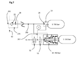
- FIG. 3 shows a series connection of different shut-off valves for limiting the pressure of a pressure accumulator system with main and secondary reservoirs and integration of a check valve in a filler tank unit 270.
- a pressure check valve unit DSV (barrier pressure 200 bar) between the automatic cylinder valve AZV3 and the auxiliary reservoir S3 (permissible operating pressure 200 bar) integrated into a storage valve block 225.
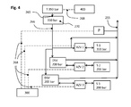
- FIG. 4 shown parallel connection of pressure check valve units to protect various partial memory corresponds largely to the example in FIG. 1 but has a parallel arrangement of the two separate pressure check valve units DSV and accumulator tank S2, S3. Of the Tank neck 265 is designed for refueling at a filling station T with 350 bar dispensing pressure.
- FIG. 5 shows an example of a pressure accumulator system with a check valve SV in an application with parallel arrangement of two accumulator tank S and positioning the check valve SV in front of a storage valve block 50.
- the filler neck unit 270 is installed in a body 60 of a motor vehicle and has a tank neck 265 on.
- the medium flows through a filter 29 and a check valve 28 in the branched pressure line 266.
- a branch of the pressure line 266 leads via a first accumulator valve block 50 with built-in check valve 28 in an accumulator tank S with 700 bar allowable filling pressure.
- the first accumulator valve block 50 additionally has a pressure regulator.
- the other branch leads into a radially arranged inlet opening 10 of a blocking bar SV designed for 200 bar barrier pressure.
- medium now passes with a maximum pressure of 200 bar via a second storage valve block 50, which also has a pressure regulator for removal of medium, in a permissible for 200 bar filling pressure second accumulator tank S.
- FIG. 6 shows by way of example a pressure storage system in which the pressure line 266 of the tank neck unit 270 without branching to a storage valve block 50 of a first pressure storage tank S (700 bar allowable operating pressure) leads. From an inlet region of the accumulator valve block 50, a further pressure line 267 leads to a subordinate second accumulator tank S (350 bar permissible operating pressure) whereby the inventive pressure check valve unit DSV with integrated removal valve secures the pressure accumulator system by closing the pressure check valve unit DSV upon reaching the preset 350 bar barrier pressure.
- a first pressure storage tank S 700 bar allowable operating pressure
- An opening of the pressure check valve unit DSV takes place only when the pressure in the first pressure storage tank and thus also in the connecting line between the pressure storage tanks by removal of medium below the barrier pressure (350 bar) of the pressure check valve unit DSV drops.
- the emptying of the pressure accumulator system is effected by a pressure regulator integrated in the accumulator valve block 50 and a pressure line 255 to a consumer.
- FIG. 7 Shows by way of example an accumulator system comprising a combination of a shut-off valve SV with electromagnetically operable valves in an application with a parallel arrangement of two accumulator tank S with different allowable operating pressures.
- the filler neck unit 270 (according to the prior art) is installed in a body 60 of a motor vehicle and has a filler neck 265 on. During the filling process, the medium flows through a filter 29 and a check valve 28 in the branched pressure line 266th
- a branch of the pressure line 266 leads via a first storage valve block 53 with built-in safety valve and check valve 28 into the first pressure storage tank S with 700 bar allowable filling pressure.
- the first accumulator valve block 53 additionally has a pressure line 267, wherein the pressure line 267 leads as a sampling line to a pressure regulator 52.
- the other branch of the pressure line 266 leads into a radially arranged inlet opening 10 of a blocking bar SV designed for a blocking pressure of 350 bar, which is connected with its outlet opening 11 directly to a second pressure storage tank S with a filling pressure of 350 bar.
- This in Fig. 7 Shut-off valve SV shown has additionally in the region of the sealing body on an opening which is connected to an electromagnetically actuated shut-off valve 51.
- the electromagnetically actuated shut-off valve 51 is here a solenoid valve that can be opened and closed electrically. Downstream of the electromagnetically actuated shut-off valve 51 is a pressure regulator 52. In the connecting line between the electromagnetically actuated shut-off valve 51 and the pressure regulator 52, the connecting line coming from the first pressure storage container S opens.
- This connection line has a pressure sensor P on.
- the electromagnetically actuated shut-off valve 51 allows the removal of medium from the second pressure storage tank S with 350 bar allowable filling pressure as soon as the pressure in the connecting line has dropped below the blocking pressure of the check valve SV.
- the check valve according to the invention via a valve receiving block 27 in a Publ tion of an accumulator tank S is arranged.
- a check valve here the entirety of the filling process controlling parts of the pressure check valve unit according to the invention is referred to.
- a valve housing 20 a piston 22 is mounted, which has two sections with different outer diameters D2, D3 and designed as a central hollow bore connecting channel 14 with the inner diameter D 1.
- the piston 22 is supported at the transition to the larger outer diameter D3 on the support A3 by a spring 23 on the valve housing 20, whereby the piston 22 is held in abutment with the cover 24 and thereby in a pressureless installation state, the passage opening 13 in the open position.
- the cylindrical piston has in the embodiment shown two sections with different outer diameters D2 and D3.
- a first piston section has a first piston active surface A1, which is formed normal to the axis of the piston 22, has a sealing edge formed as a chamfer on an edge of the piston, and a first sliding surface with an outer diameter D2.
- a second piston section has a second piston acting surface A2, a support A3 for the spring 23 and a second sliding surface with an outer diameter D3.
- the connecting channel 14 is formed as an axial bore over the entire length of the piston 22 and has an inner diameter D 1.
- the connecting channel 14 connects the two piston reaction surfaces A1, A2 and is corresponding to the Embodiment of the valve housing 20 and the operating state of the check valve flows through the medium.
- the piston 22 is sealed in the two sections with different outer diameters D2, D3 of sealing elements 41,42 so that the space with the spring 23 between these seals can breathe freely through the ventilation opening 12 to atmospheric pressure.
- the sealing elements 41, 42 may optionally be mounted in the piston 22 or as shown in the valve housing 20.
- the seal 43 seals the adjustable cover 24 against the valve housing 20.
- medium can flow through the inlet opening 10 in the inlet region 17 of the valve chamber via the passage opening 13 and through the connecting channel 14 into the storage area 19 of the valve chamber, and subsequently through the outlet opening 11 in FIG get the subsequent accumulator tank S.
- the piston 22 overcomes the spring force 23, the piston 22 is pushed against the sealing body 21.
- the check valve closes. This pressure corresponds to the barrier pressure.
- the piston at the outer diameter D2 to the sealing body 21 seals.
- the check valve remains closed because the pressure increase no longer acts on the first piston effective area A1.
- the valve still remains closed, as the closing force by the Pressure in the outlet opening 11 on the piston effective area A2, minus the spring force of the spring 23, is determined and this state has not changed.
- the spring force of the spring 23 is additionally adjustable with the depth of engagement of the lid 24. In order to obtain a good pressure distribution to the second piston effective area A2 are either spacer 25 on the cover 24 or represent appropriate exemptions on the piston.
- FIG. 9 shows an example of a complete pressure check valve unit according to the invention. This essentially covers all parts of the Fig. 8 shown blocking valve with the same reference numerals.
- the modified valve housing is designated here by the reference numeral 26 and has an exemplary removal channel 15 shown between the storage area 19 and the inlet opening 10 in which a removal valve 30 is arranged that opens and closes according to the pressure conditions.
- An advantageous embodiment results in the embodiment of the removal valve 30 as a mechanical ball valve, wherein the ball valve is permanently closed by a spring 31 without pressure.
- the removal valve 30 can open and medium flows from the storage area 19 through the withdrawal channel 15 and the channel 16 in the spring -Fixierschraube 32 back to the inlet opening 10 back. Only then is a removal of medium from the downstream pressure storage system possible, provided that the downstream pressure storage system has no further removal devices. As a result, the pressure in the storage area 19 decreases and, depending on the spring hysteresis of the spring 23 and the friction of the sealing elements 41, 42, the piston 22 is pressed downwards by the check valve in a time-delayed manner Passage opening 13 is released.
- the gasket 48 seals a bleed valve 30 screwed as an assembly against the valve body 26.
- the bleed valve can also be used in combination with electromagnetic valves and a pressure sensor P for arbitrary control of the timing for opening the pressure check valve unit.
- the backup of the screwed lid 24 and thus the secure determination of the barrier pressure can be as technically usual z. B. be achieved with a clamping screw 35. Necessary holes can be sealed by screws with sealing rings 33 and 34, also as is technically customary, to the outside.
- An ideal complement is a combination of pressure check valve unit with a pressure relief valve 36 in a common valve housing 26 between the conduit on the removal channel 15 and serving as a space for the spring 23 relief region 18 with relief opening 12.
- the safe removal of escaping medium eliminates any further safety-critical factor ,
- Opening of the check valve takes place only when the pressure in the outlet opening 11 drops due to the fact that medium is removed in the subsequent system via a separate location and thereby the pressure drops below the barrier pressure.
- the check valve opens either by the pressure in the storage area 19 drops below the closing pressure of the check valve by removal from the accumulator tank by the consumer or by means of the in Fig. 9 shown in the removal channel 15,15a arranged removal valve 30th
- FIG. 8 A further variant of a shut-off valve SV according to the invention, not shown in the figures, varies from FIG Fig. 8 illustrated embodiment.
- the in the Fig. 8 arranged in the cover 24 outlet opening 11 is moved into the valve housing 20 in alignment with the axis of movement of the piston 22 under the sealing body 23.
- the lid 24 closes the valve chamber now without the outlet opening tight.
- the sealing body 21 In all embodiments in which a sealing body 21 is used, the sealing body 21 must be sealed to the valve housing 20 for safety reasons, so that no additional forces arise and can act on the sealing edge of the piston 22.
- the invention is suitable both for stationary pressure accumulator systems and for pressure accumulator systems in vehicles.
- vehicle in this patent includes, for example, motor vehicles, rail vehicles, and water and air vehicles. All stated pressures are exemplary and do not limit the invention and the range of pressures for which the invention is claimed.
Landscapes
- Engineering & Computer Science (AREA)
- Mechanical Engineering (AREA)
- General Engineering & Computer Science (AREA)
- Physics & Mathematics (AREA)
- Fluid Mechanics (AREA)
- Filling Or Discharging Of Gas Storage Vessels (AREA)
- Supply Devices, Intensifiers, Converters, And Telemotors (AREA)
Abstract
Description
Die vorliegende Erfindung betrifft ein Druckspeichersystem sowie Verfahren zum Betreiben eines derartigen Druckspeichersystems.The present invention relates to a pressure accumulator system and method for operating such a pressure accumulator system.
Erfindungsgemäße Vorrichtungen können beispielsweise in Form von Tanks oder Tanksystemen von Kraftfahrzeugen eingesetzt werden, um bei einem Tank- oder Befüllvorgang ein Überfüllen einzelner Druckspeicherbehälter mit Kraftstoff zu verhindern. Nach dem Befüllvorgang muss der Kraftstoff zum Verbrauch wieder entnommen werden. Dafür sind unterschiedliche Anordnungen von Druckspeicherbehältern und Ventilen, sowie Verfahren zu deren Betrieb bekannt.Devices according to the invention can be used, for example, in the form of tanks or tank systems of motor vehicles in order to prevent overfilling of individual pressure storage containers with fuel during a tank or filling operation. After filling, the fuel must be removed again for consumption. For different arrangements of accumulator tanks and valves, and methods for their operation are known.
Speziell im Fall von mit Erdgas oder Wasserstoff betriebenen Kraftfahrzeugen wird einerseits eine große Reichweite gewünscht und steht andererseits oft nur begrenzter Raum zum Einbau der Druckspeicherbehälter zur Verfügung, sodass es häufig von Vorteil ist, mehrere Druckspeicherbehälter unterschiedlicher Kapazität an mehreren Stellen im Fahrzeug unterzubringen. Aber auch bei stationären Anlagen, insbesondere bei Arbeitsmaschinen wird eine lange Betriebsdauer gewünscht und es steht oft nur begrenzter Raum zur Verfügung.Especially in the case of vehicles powered by natural gas or hydrogen, on the one hand a large range is desired and on the other hand often only limited space for installation of accumulator available, so it is often advantageous to accommodate several pressure accumulator different capacity at several points in the vehicle. But even in stationary systems, especially in work machines, a long service life is desired and there is often only limited space available.
Die
Die Gasbehälteranordnung der
Die beiden Gasbehälter sind über eine gemeinsame Gasleitung sowohl mit dem Gasmotor als auch mit einem Befüllstutzen verbunden. Dieser ist über einen entsprechenden Zapfschlauch verbindbar, um ein hoch verdichtetes Gas, wie zum Beispiel Erdgas aus einem oder mehreren Vorratsbehältern der Erdgasbetankungsanlage in die Gasbehälter der Gasbehälteranordnung zu füllen. Der Befüllstutzen ist mit einem Tankklappenschalter ausgestattet, der ein Öffnen und Schließen der Tankklappe des Befüllstutzens erfasst. Wahlweise kann der Tankklappenschalter auch zum Erkennen des Vorhandenseins einer Zapfpistole in dem geöffneten Befüllstutzen ausgebildet sein und eine elektronische Busverbindung über den Befüllschlauch ermöglicht die Kommunikation zwischen der Tankstelle und einer Steuereinrichtung im Fahrzeug.The two gas containers are connected via a common gas line with both the gas engine and with a filling nozzle. This is connectable via a corresponding dispensing hose to fill a highly compressed gas, such as natural gas from one or more reservoirs of the natural gas refueling system in the gas container of the gas container assembly. The filler neck is equipped with a tank flap switch that detects opening and closing of the tank flap of the filler neck. Optionally, the tank flap switch can also be designed to detect the presence of a fuel nozzle in the open filling nozzle and an electronic bus connection via the filling hose enables communication between the gas station and a control device in the vehicle.
Die
Bei den genannten Anwendungen ist es erwünscht, dass ein zulässiger Betriebsdruck eines Druckspeicherbehälters oder eines Druckspeichersystems im Verlauf eines Befüllvorganges zuverlässig eingehalten und so höchste Betriebssicherheit gewährleistet wird. Der Befüllvorgang soll möglichst schnell und mit nur geringen Energieverlusten durchführbar sein. Verschleiß an Ventilkomponenten soll gering gehalten und Beschädigungen an Druckspeicherbehältern und Druckleitungen sollen verhindert werden. Außerdem ist es erwünscht die Verrohrung der Druckspeichersysteme zu vereinfachen und die Anzahl und Komplexität der Druckleitungen zu vermindern.In the applications mentioned, it is desirable that a permissible operating pressure of a pressure accumulator tank or a pressure accumulator system reliably maintained during the course of a filling process and thus highest reliability is ensured. The filling should be carried out as quickly as possible and with only low energy losses. Wear on valve components should be kept low and damage to accumulator tanks and pressure lines should be prevented become. In addition, it is desirable to simplify the piping of the pressure accumulator systems and to reduce the number and complexity of the pressure lines.
Druckspeicherbehälter für mobile Anwendungen werden je nach Anwendungsart in der Bauweise dem entsprechenden Druckniveau angepasst und gebaut. Dies bedingt Speicher, die in ihrer Festigkeit dem Betriebsdruck und den ECE-Richtlinien entsprechen und bei Hochdruckanlagen, z.B. oberhalb 200 bar, entsprechenden Platz benötigen. Kleine Druckspeicherbehälter mit jeweils gleichem zulässigem Betriebsdruck, oder modular zusammengesetzte Teildruckspeicher mit gleichem zulässigem Betriebsdruck bauen dadurch im Verhältnis sehr groß und teuer und haben sich daher bisher nicht durchgesetzt. Auch ist im Stand der Technik keine ausreichend zuverlässige technische Lösung bekannt, die das gleichzeitige Befüllen von Druckspeicherbehältern mit unterschiedlichem zulässigem Betriebsdruck an demselben Tankstutzen ermöglicht.Pressure accumulator tanks for mobile applications are adapted and built according to the type of application in the construction of the appropriate pressure level. This requires storage tanks that are robust in terms of operating pressure and ECE guidelines and high pressure equipment, e.g. above 200 bar, need appropriate space. Small accumulator tank, each with the same permissible operating pressure, or modularly assembled partial accumulator with the same permissible operating pressure thereby build in proportion very large and expensive and have therefore not prevailed. Also, in the prior art, a sufficiently reliable technical solution is known that allows the simultaneous filling of accumulator tanks with different permissible operating pressure at the same tank neck.
Nach derzeit geltenden gesetzlichen Bestimmungen müssen alle Druckspeicherbehälter eines Systems auf einen identen zulässigen Betriebsdruck (maximalen Arbeitsdruck) ausgelegt sein. Es ist derzeit auch verboten an Tankstellen zu tanken, deren Betankungsdruck (Zapfdruck) den maximalen Arbeitsdruck der in einem Kraftfahrzeug verbauten Druckspeicherbehälter übersteigt.Under current legislation, all accumulator tanks in a system must be designed for an identical permissible operating pressure (maximum working pressure). It is currently also prohibited to refuel at petrol stations whose refueling pressure (dispensing pressure) exceeds the maximum working pressure of the accumulator tank installed in a motor vehicle.
Es ist eine Aufgabe der Erfindung, Druckspeichersysteme in dieser Hinsicht zu verbessern und insbesondere kombinierte Ventilanordnungen anzugeben die, zum Teil auch ohne elektrische und elektronische Komponenten, die Sicherheit von Systemen von Druckspeicherbehältern mit unterschiedlichem zulässigem Betriebsdruck gewährleisten.It is an object of the invention to improve pressure accumulator systems in this regard, and more particularly to provide combined valve assemblies which, in part, even without electrical and electronic components, ensure the safety of systems of accumulator tanks of varying allowable operating pressure.
Es ist außerdem eine Aufgabe der Erfindung verbesserte Verfahren zum Betreiben von Druckspeichersystemen anzugeben, die eine erhöhte Betriebssicherheit ermöglichen.It is also an object of the invention to provide improved methods for operating pressure accumulator systems, which enable increased reliability.
Die Lösung der Aufgaben erfolgt durch ein Verfahren zum Betreiben eines Druckspeichersystems, wobei zumindest zwei einen unterschiedlichen zulässigen Betriebsdruck aufweisende Druckspeicherbehälter, wobei zumindest ein Druckspeicherbehälter einen zulässigen Betriebsdruck aufweist, der niedriger ist als ein maximaler an einem Tankstutzen aufbringbarer Druck, und wobei der zumindest eine Druckspeicherbehälter mit einem niedrigeren zulässigen Betriebsdruck durch zumindest eine vorgeschaltete, einen durch den niedrigeren zulässigen Betriebsdruck festgelegten Sperrdruck aufweisende, Einrichtung gegen unzulässigen Druckanstieg geschützt wird, gleichzeitig und über denselben Tankstutzen befüllt werden.The objects are achieved by a method for operating an accumulator system, wherein at least two pressure accumulator containers having a different permissible operating pressure, wherein at least one pressure accumulator container has a permissible operating pressure which is lower than a maximum pressure which can be applied to a tank stub, and wherein the at least one pressure accumulator container With a lower allowable operating pressure by at least one upstream, a set by the lower permissible operating pressure having barrier device, the device is protected against inadmissible increase in pressure, are filled simultaneously and the same tank neck.
Durch die kombinierte Anwendung von mechanisch betätigten Sperrventilen, Drucksperrventileinheiten, Rückschlagventilen und elektromagnetischen Ventilen zum Zu- und Abschalten können beliebige Niveaus von zulässigen Betriebsdrucken in unterschiedlichen Druckspeichersystemen oder Teilen von Druckspeichersystemen umgesetzt werden, sodass kleinere, aber auch dünnwandigere, billigere Speicher Anwendung finden können. Weiters wird dadurch die Verwendung von Freiformspeichern möglich, die zusätzlich zu den Hauptspeichern bestehende Hohlräume in und an einem Kraftfahrzeug oder einer Arbeitsmaschine nutzen und dadurch die Fahrzeugreichweite oder die Betriebsdauer erhöhen.The combined use of mechanically actuated check valves, pressure check valve units, check valves, and electromagnetic valves to turn on and off allows any levels of allowable operating pressures to be implemented in different accumulator systems or parts of accumulator systems, allowing smaller, but also thinner, cheaper accumulators to be used. Furthermore, this makes it possible to use free-form memories, which in addition to the main memories use existing cavities in and on a motor vehicle or a work machine and thereby increase the vehicle range or the operating time.
Die Lösung der Aufgabe erfolgt auch durch ein Druckspeichersystem, wobei das Druckspeichersystem einen Tankstutzen, zumindest zwei Druckspeicherbehälter, Druckleitungen und zumindest eine Entnahmestelle aufweist, wobei zumindest ein Druckspeicherbehälter einen zulässigen Betriebsdruck aufweist, der niedriger ist als ein maximaler an dem Tankstutzen aufbringbarer Druck, wobei den zumindest einen Druckspeicherbehälter mit einem niedrigeren zulässigen Betriebsdruck zumindest eine vorgeschaltete, einen durch den niedrigeren zulässigen Betriebsdruck festgelegten Sperrdruck aufweisende Einrichtung, gegen unzulässigen Druckanstieg schützt. Diese vorgeschaltete Einrichtung kann zum Beispiel als ein Sperrventil und/oder als Drucksperrventileinheit oder ein elektromagnetisch betätigbares Absperrventil im Zusammenwirken mit einer elektronischen Druckmesseinrichtung und einer Steuereinheit (300) oder auch eine Kombination aus den genannten vorschaltbaren Einrichtungen ausgebildet sein.The problem is solved by a pressure accumulator system, wherein the pressure accumulator system has a tank neck, at least two accumulator tank, pressure lines and at least one sampling point, wherein at least one accumulator tank has a permissible operating pressure which is lower than a maximum aufbringbarer on the tank neck pressure, wherein the protects at least one accumulator tank with a lower allowable operating pressure at least one upstream, one set by the lower allowable operating pressure barrier pressure device, against inadmissible increase in pressure. This upstream device may for example be designed as a check valve and / or as a pressure check valve unit or an electromagnetically actuated shut-off valve in cooperation with an electronic pressure measuring device and a control unit (300) or a combination of said upstream devices.
Durch die Anwendung von rein mechanisch einen festgelegten Sperrdruck überwachenden Einrichtungen, wobei diese Einrichtungen dauerhaft mit einzelnen Druckspeicherbehältern und/oder Teilbereichen eines Druckspeichersystems wirkverbunden sind, ergibt sich eine hohe Sicherheit gegen Fehlbetankung und wirksamer Schutz gegen unzulässigen Druckanstieg in einzelnen Druckspeicherbehältern. Rein elektronisch überwachende Systeme können durch fehlerhafte Druckmessungen und/oder Schaltvorgänge an elektromagnetischen Ventilen gefährliche Zustände im Druckspeichersystem herbeiführen. Mechanische und elektrische/elektronische Komponenten werden in erfindungsgemäßen Druckspeichersystemen bevorzugt gemeinsam als zusätzliche Sicherungseinrichtungen eingesetzt.By the use of purely mechanical a specified barrier pressure monitoring devices, these devices are permanently operatively connected to individual pressure storage tanks and / or portions of an accumulator system, there is a high security against misfuelling and effective protection against unacceptable pressure increase in individual pressure storage tanks. Purely electronically monitoring systems can cause dangerous conditions in the pressure storage system due to faulty pressure measurements and / or switching operations on electromagnetic valves. Mechanical and electrical / electronic components are preferably used together as additional safety devices in pressure accumulator systems according to the invention.
Gemäß einem Aspekt der Erfindung wird die Aufgabe gelöst durch ein Verfahren zum Betreiben eines Druckspeichersystems, wobei zumindest zwei einen unterschiedlichen zulässigen Betriebsdruck aufweisende Druckspeicherbehälter gleichzeitig und über denselben Tankstutzen befüllt werden.According to one aspect of the invention, the object is achieved by a method for operating an accumulator system, wherein at least two pressure accumulator containers having a different permissible operating pressure are filled simultaneously and via the same tank stub.
Bevorzugt weist dieser eine Tankstutzen mechanische Dimensionen und/oder andere Kodierungen auf, sodass der Tankstutzen mit allen Zapfeinrichtungen verbindbar ist die Kraftstoff/Medium bis zu einem höchsten an Tankstellen oder anderen Betankungseinrichtungen verfügbaren Zapfdruck (in Zukunft beispielsweise 700 oder 900 Bar) zur Verfügung stellen. Die dem Tankstutzen nachgeschaltete und dem Druckspeichersystem vorgeschaltete Einrichtung (z.B. Sperrventil/Drucksperrventileinheit) schützt Druckspeicherbehälter mit einem niedrigeren zulässigen Betriebsdruck gegen unzulässigen Druckanstieg.Preferably, this has a tank filler neck mechanical dimensions and / or other codes, so that the filler neck is connectable to all dispensing devices fuel / medium up to a highest available at gas stations or other refueling facilities dispensing pressure (in the future, for example, 700 or 900 bar) provide. The downstream of the tank neck and upstream of the accumulator system (e.g., check valve / check valve unit) protects accumulator tanks with a lower allowable operating pressure against inadmissible pressure rise.
Gemäß einem weiteren Aspekt der Erfindung wird die Aufgabe gelöst durch ein Verfahren zum Betreiben eines Druckspeichersystems, wobei zur Entnahme von Medium aus dem Druckspeichersystem die den Druckspeicherbehältern mit dem niedrigeren zulässigen Betriebsdruck vorgeschalteten Sperrventile und/oder Drucksperrventileinheiten abhängig von der Druckabnahme im Druckspeichersystem entsprechend dem für die jeweiligen Sperrventile und/oder Drucksperrventileinheiten festgelegten Sperrdruck selbsttätig öffnen.According to a further aspect of the invention, the object is achieved by a method for operating an accumulator system, wherein for the removal of medium from the accumulator system the shut-off valves and / or pressure check valve units upstream of the accumulator tanks with the lower permissible operating pressure, depending on the pressure decrease in the accumulator system according to the each barrier valves and / or pressure check valve units defined barrier pressure open automatically.
Bei geeigneter Anordnung (siehe beispielhafte Figuren) von Sperrventilen und/oder Drucksperrventileinheiten kann ohne elektronische Druckmessung und Steuerung Medium/Kraftstoff aus Teilen des Druckspeichersystems mit unterschiedlichem zulässigem Betriebsdruck entnommen werden.With a suitable arrangement (see exemplary figures) of check valves and / or pressure check valve units can be removed without electronic pressure measurement and control medium / fuel from parts of the pressure storage system with different allowable operating pressure.
Weiterbildungen der Erfindung sind in den abhängigen Ansprüchen, der Beschreibung sowie den beigefügten Zeichnungen angegeben.Further developments of the invention are specified in the dependent claims, the description and the accompanying drawings.
Eine bevorzugte, einen durch einen niedrigeren zulässigen Betriebsdruck festgelegten Sperrdruck aufweisende, vorgeschaltete Einrichtung ist beispielsweise ein Sperrventil für einen Druckspeicherbehälter für ein Medium, wobei ein Ventilgehäuse eine Ventilkammer mit einer Zulauföffnung und einer dem Druckspeicherbehälter zugewandten Auslassöffnung, einen beweglichen Kolben, und zumindest eine Feder aufweist, wobei der Kolben zumindest einen axialen Verbindungskanal aufweist und durch zumindest zwei in der Ventilkammer angeordnete Dichtelemente axial beweglich geführt ist, wobei eine einem Einlassbereich der Ventilkammer zugewandte erste Kolbenwirkfläche des Kolbens und ein Dichtkörper oder das Ventilgehäuse einen Ventilsitz bilden, und wobei durch Änderung des Druckes in einem an eine zweite Kolbenwirkfläche angrenzenden Speicherbereich der Ventilkammer der Kolben axial bewegbar ist und eine zwischen der Zulauföffnung und der Auslassöffnung angeordnete Durchlassöffnung reversibel verschlossen und geöffnet werden kann, wobei die Durchlassöffnung in drucklosem Zustand durch die Feder offen gehalten wird.A preferred, a predetermined by a lower allowable operating pressure barrier pressure, upstream device is, for example, a check valve for a pressure storage tank for a medium, wherein a valve housing having a valve chamber with an inlet opening and the pressure accumulator container facing outlet, a movable piston, and at least one spring wherein the piston has at least one axial connecting channel and is axially movably guided by at least two sealing elements arranged in the valve chamber, a first piston acting surface of the piston facing an inlet region of the valve chamber and a sealing body or the valve housing forming a valve seat, and wherein by changing the pressure in a storage area adjacent to a second piston effective area of the valve chamber, the piston is axially movable, and a passage opening r arranged between the inlet opening and the outlet opening can be reversibly closed and opened, wherein the passage opening is kept open in a pressureless state by the spring.
Es resultiert ein rein mechanisches Sperrventil, das aufgrund einer eingestellten Federkraft ab einem bestimmten Druck die Durchlassöffnung dicht verschließt und weder bei weiterer Druckzunahme oder Druckabnahme bis Unterdruck in der Zulauföffnung öffnet und somit immer verschlossen bleibt. Die Entnahme von Medium erfolgt an einer oder mehreren anderen Stellen im Druckspeichersystem.The result is a purely mechanical shut-off valve, which tightly closes the passage opening due to a set spring force from a certain pressure and neither opens further pressure increase or pressure decrease to negative pressure in the inlet opening and thus always remains closed. The removal of medium takes place at one or more other points in the accumulator system.
Eine weitere bevorzugte, einen durch einen niedrigeren zulässigen Betriebsdruck festgelegten Sperrdruck aufweisende, vorgeschaltete Einrichtung ist beispielsweise eine Drucksperrventileinheit für einen Druckspeicherbehälter für ein Medium, wobei ein Ventilgehäuse eine Ventilkammer mit einer Zulauföffnung und einer dem Druckspeicherbehälter zugewandten Auslassöffnung, einen beweglichen Kolben, und zumindest eine Feder aufweist, wobei der Kolben zumindest einen axialen Verbindungskanal aufweist und durch zumindest zwei in der Ventilkammer angeordnete Dichtelemente axial beweglich geführt ist, wobei eine einem Einlassbereich der Ventilkammer zugewandte erste Kolbenwirkfläche des Kolbens und ein Dichtkörper oder das Ventilgehäuse einen Ventilsitz bilden, und wobei durch Änderung des Druckes in einem an eine zweite Kolbenwirkfläche angrenzenden Speicherbereich der Ventilkammer der Kolben axial bewegbar ist und eine zwischen der Zulauföffnung und der Auslassöffnung angeordnete Durchlassöffnung reversibel verschlossen und geöffnet werden kann, wobei die Durchlassöffnung in drucklosem Zustand durch die Feder offen gehalten wird und wobei der Speicherbereich der Ventilkammer über einen Entnahmekanal und ein Entnahmeventil mit dem Einlassbereich verbindbar angeordnet ist.Another preferred upstream device having a barrier pressure set by a lower allowable operating pressure For example, is a pressure check valve unit for a pressure accumulator tank for a medium, wherein a valve housing has a valve chamber with an inlet opening and an outlet opening facing the accumulator tank, a movable piston, and at least one spring, wherein the piston has at least one axial connection channel and at least two in the Valve chamber arranged sealing elements is axially movably guided, wherein an inlet region of the valve chamber facing the first piston effective surface of the piston and a sealing body or the valve housing form a valve seat, and wherein the piston is axially movable by changing the pressure in an adjacent to a second piston effective area storage area of the valve chamber and a passage opening arranged between the inlet opening and the outlet opening can be reversibly closed and opened, the passage opening being open in a pressureless state by the spring and wherein the storage area of the valve chamber is arranged connectable to the inlet area via a removal channel and a removal valve.
Es resultiert eine rein mechanische Drucksperrventileinheit, die aufgrund einer eingestellten Federkraft ab einem bestimmten Druck die Durchlassöffnung dicht verschließt und weder bei weiterer Druckzunahme oder Druckabnahme bis Unterdruck in der Zulauföffnung öffnet und somit immer verschlossen bleibt.The result is a purely mechanical pressure check valve unit, which tightly closes the passage opening due to a set spring force from a certain pressure and opens neither with further increase in pressure or pressure decrease to negative pressure in the inlet opening and thus always remains closed.
Die Entnahme von Medium aus dem Druckspeicherbehälter erfolgt über einen Entnahmekanal und ein Entnahmeventil das mit einem Einlassbereich verbindbar angeordnet ist, oder auch an einer oder mehreren anderen Stellen im Druckspeichersystem.The removal of medium from the pressure storage container via a removal channel and a removal valve which is arranged connectable to an inlet region, or at one or more other locations in the pressure storage system.
Der erfinderische Vorteil dieser mechanischen Drucksperrventileinheit liegt beim Befüllvorgang darin, dass ein nachgeschaltetes Druckspeichersystem nur den Druck erreicht der gewünscht ist und unabhängig vom Druck vor der Drucksperrventileinheit und ohne einen elektromagnetischen Aktuator die Drucksperrventileinheit immer sicher verschlossen bleibt und somit den Druck im nachgeschalteten Druckspeichersystem einerseits sicher hält und eine weitere Druckzunahme durch nachströmendes Medium nicht zulässt. Ein weiterer Vorteil dieser Ventilausführung liegt darin, dass zwar bei Undichtigkeiten am Dichtsitz zwischen Kolben und Dichtkörper oder Ventilgehäuse das nachgeschaltete Druckspeichersystem einer nicht gewünschten Druckerhöhung ausgesetzt sein kann, wobei mit Zunahme des Druckes auf der Auslassseite die Anpresskraft des Kolbens auf den Dichtkörper oder das Ventilgehäuse zunimmt und somit die Undichtigkeit wieder verringert wird.The inventive advantage of this mechanical pressure check valve unit is during the filling process is that a downstream accumulator system only reaches the pressure desired and regardless of the pressure before the pressure check valve unit and without an electromagnetic actuator, the pressure check valve unit always remains securely closed and thus keeps the pressure in the downstream pressure storage system on the one hand safe and does not allow further pressure increase by inflowing medium. Another advantage of this valve design is that, although in leaks at the sealing seat between the piston and the sealing body or valve housing downstream pressure accumulator system may be exposed to a non-desired pressure increase, with increasing the pressure on the outlet side increases the contact pressure of the piston on the sealing body or the valve housing and thus the leak is reduced again.
Besonders vorteilhaft wirkt sich aus, dass die Durchlassöffnung in drucklosem Zustand durch die Kraft der Feder offen gehalten wird. So kann das Medium bis zur Schlussphase des Tankvorganges ungehindert in den Druckspeicherbehälter strömen und schädliche Vibrationen im Bereich der Ventilkammer werden vermieden.It has a particularly advantageous effect that the passage opening is kept open in the pressureless state by the force of the spring. Thus, the medium can flow unimpeded into the pressure accumulator tank until the final phase of the refueling process and harmful vibrations in the area of the valve chamber are avoided.
Wenn der Druck in der Zulauföffnung unter den Druck im Speicherbereich abfällt, kann das Entnahmeventil geöffnet werden und es fließt Medium vom Speicherbereich durch den Entnahmekanal zur Zulauföffnung. Dadurch wird eine Entnahme von Medium aus dem nachgeschalteten Druckspeicherbehälter oder -system über die Zuleitung möglich. Das erleichtert die Verwendung von zusätzlichen Druckspeicherbehältern und vereinfacht die Verrohrung von Druckspeichersystemen erheblich. Vorzugsweise ist das Entnahmeventil der Drucksperrventileinheit als Kugel- oder Kegelventil ausgebildet und wird durch eine Stellfeder in einem drucklosen Zustand geschlossen gehalten, wobei die Stellfeder auf der dem Einlassbereich zugewandten Seite des Entnahmeventils angeordnet ist. Dadurch ist das Entnahmeventil durch die Stellfeder bei Überdruck in der Zulauföffnung und auch drucklos permanent verschlossen. Wenn der Druck in der Zulauföffnung unter den Druck im Speicherbereich abfällt, kann in Abhängigkeit von der Federkraft der Stellfeder das Entnahmeventil öffnen und es fließt Medium vom Speicherbereich durch den Entnahmekanal zurück zur Zulauföffnung.When the pressure in the inlet opening drops below the pressure in the storage area, the extraction valve can be opened and medium flows from the storage area through the extraction channel to the inlet opening. As a result, a removal of medium from the downstream pressure storage container or system via the supply line is possible. This facilitates the use of additional accumulator tanks and greatly simplifies the piping of accumulator systems. Preferably, the removal valve of the pressure check valve unit is designed as a ball or plug valve and is kept closed by a spring in a non-pressurized state, wherein the spring is arranged on the inlet side facing the discharge valve. As a result, the extraction valve is permanently closed by the spring in case of overpressure in the inlet opening and also without pressure. When the pressure in the inlet opening drops below the pressure in the storage area, the extraction valve can open depending on the spring force of the adjusting spring and medium flows from the storage area through the extraction channel back to the inlet opening.
In einer besonders bevorzugten Ausführungsform der Drucksperrventileinheit ist die Federkraft der Stellfeder über eine Feder-Fixierschraube einstellbar. Der große Vorteil dieser Anordnung liegt darin, dass durch die Einstellmöglichkeit der Federkraft das Entnahmeventil beliebig weit unter dem Sperrdruck der Drucksperrventileinheit wieder öffnet. Somit ist aber auch der Zeitpunkt und das Druckniveau im Speicherbereich der Ventilkammer, ab dem die Drucksperrventileinheit öffnet, einstellbar.In a particularly preferred embodiment of the pressure check valve unit, the spring force of the spring is adjustable via a spring-fixing screw. The great advantage of this arrangement is that the withdrawal valve opens arbitrarily far below the locking pressure of the pressure check valve unit by the adjustment of the spring force. Thus, however, the time and the pressure level in the storage area of the valve chamber, from which the pressure check valve unit opens, adjustable.
In einer weiteren besonders bevorzugten Ausführungsform der Drucksperrventileinheit ist die Feder-Fixierschraube koaxial mit der Stellfeder angeordnet und weist einen axialen Kanal auf der als Drossel ausgebildet ist. Dadurch ist eine gedämpfte Zuschaltung von Medium vom Speicherbereich der Ventilkammer durch die Drosselstelle im Kanal der Feder-Fixierschraube zur Zulauföffnung und somit ein langsamer Druckabbau im Speicherbereich möglich. Druckspitzen im Bereich der Zulauföffnung werden vermieden.In a further particularly preferred embodiment of the pressure check valve unit, the spring-fixing screw is arranged coaxially with the adjusting spring and has an axial channel which is designed as a throttle. As a result, a damped connection of medium from the storage area of the valve chamber through the throttle point in the channel of the spring-fixing screw to the inlet opening and thus a slow pressure reduction in the storage area is possible. Pressure peaks in the region of the inlet opening are avoided.
In einer bevorzugten Ausführung sind der Entnahmekanal und das Entnahmeventil im Ventilgehäuse integriert angeordnet. In einer weiteren bevorzugten Ausführungsform sind der Entnahmekanal und das Entnahmeventil im Kolben integriert angeordnet. Dadurch wird ein Platz sparender Aufbau ermöglicht und es werden sowohl die Herstellung und der Zusammenbau als auch die Montage der Drucksperrventileinheit in Druckspeichersystemen vereinfacht.In a preferred embodiment, the removal channel and the removal valve are arranged integrated in the valve housing. In another preferred embodiment, the removal channel and the removal valve are arranged integrated in the piston. This allows a space-saving design and it is both the manufacture and assembly as well as the installation of the pressure check valve unit in accumulator systems simplified.
Vorzugsweise sind die erste Kolbenwirkfläche und der Dichtkörper oder das Ventilgehäuse des Sperrventils und/oder der Drucksperrventileinheit so ausgebildet, dass in einer Schließposition des Kolbens eine Dichtwirkung an einer Dichtkante im Bereich des äußeren Randes der ersten Kolbenwirkfläche auftritt.Preferably, the first piston effective surface and the sealing body or the valve housing of the check valve and / or the pressure check valve unit are formed so that in a closed position of the piston, a sealing effect on a sealing edge in the region of the outer edge of the first piston effective surface occurs.
Äußerer Rand bedeutet hier, von der Achse des Kolbens betrachtet, radial außen liegend. Der äußere Rand des Kolbens kann beispielsweise im Bereich der ersten Kolbenwirkfläche schräg gefast sein. Auch kann die erste Kolbenwirkfläche am äußeren Rand einen erhöhten Wulst aufweisen, um die Dichtwirkung in diesem Bereich zu lokalisieren.Outer edge here, viewed from the axis of the piston, means radially outward. The outer edge of the piston can be chamfered obliquely, for example in the region of the first piston effective area. Also, the first piston acting surface at the outer edge may have an increased bead to locate the sealing effect in this area.
Dadurch wird bei Überschreiten eines Sperrdrucks bzw. bei Anstieg des Druckes über den Sperrdruck auf den Kolben keine Kraft mehr gegen die Schließrichtung des Kolbens ausgeübt. Der Sperrdruck und das Schließverhalten der erfindungsgemäßen Sperrventile und/oder Drucksperrventileinheiten werden somit unabhängig vom Druck in der Zulauföffnung. Außerdem kann bei geschlossenem Ventil auch bei einem Druckanstieg in der Zulauföffnung durch den Druck in der Zulauföffnung keine axiale Kraft auf den Kolben ausgeübt werden und das Sperrventil und/oder die Drucksperrventileinheit bleibt auch bei extremen Druckstößen sicher geschlossen.As a result, when a blocking pressure is exceeded or when the pressure on the blocking pressure on the piston is exceeded, no force is exerted against the closing direction of the piston. The barrier pressure and the closing behavior of the check valves and / or pressure check valve units according to the invention thus become independent of the pressure in the inlet opening. In addition, with the valve closed even with a pressure increase in the inlet opening by the pressure in the inlet opening no axial force can be exerted on the piston and the check valve and / or the pressure check valve unit remains securely closed even in extreme pressure surges.
Es wird außerdem sichergestellt, dass das Sperrventil und/oder die Drucksperrventileinheit auch dann geschlossen bleibt, wenn der Druck in der Zulauföffnung unter den Sperrdruck absinkt, bei dem der Kolben zuvor geschlossen hat, da die nun fortwährende Schließkraft im Wesentlichen nur durch den Druck im Speicherbereich der Ventilkammer auf die Kolbenwirkfläche abzüglich der Federkraft der Feder bestimmt wird.It is also ensured that the check valve and / or the pressure check valve unit remains closed even when the pressure in the inlet opening drops below the barrier pressure at which the piston has previously closed, since the now ongoing closing force substantially only by the pressure in the storage area the valve chamber is determined on the piston effective area minus the spring force of the spring.
Dadurch, dass die Zulauföffnung vorzugsweise radial außerhalb der Kolbenwirkfläche in den Einlassbereich der Ventilkammer mündet, wird zusätzlich sichergestellt, dass durch den Druck in der Zulauföffnung keine axiale Kraft auf den Kolben ausgeübt werden kann.Characterized in that the inlet opening preferably opens radially outside the piston effective area in the inlet region of the valve chamber, it is additionally ensured that no axial force can be exerted on the piston by the pressure in the inlet opening.
Vorzugsweise ist die zweite Kolbenwirkfläche grösser ausgebildet als die erste Kolbenwirkfläche. Durch eine relativ größere zweite Kolbenwirkfläche ist es möglich kleinere Werte für den Sperrdruck der Sperrventile und/oder Drucksperrventileinheiten zu realisieren.Preferably, the second piston effective area is formed larger than the first piston effective area. By a relatively larger second piston effective area, it is possible to realize smaller values for the blocking pressure of the check valves and / or pressure check valve units.
Besonders bevorzugt ist der Kolben zylindrisch und weist an seiner Au-βenseite Gleitflächen in zumindest zwei Bereichen mit vorzugsweise unterschiedlichen Durchmessern auf.Particularly preferably, the piston is cylindrical and has on its Au βenseite sliding surfaces in at least two areas with preferably different diameters.
Besonders bevorzugt sind die zumindest zwei Dichtelemente in entsprechenden Ausnehmungen im Ventilgehäuse angeordnet. Die kostengünstigste Variante wäre, die Dichtelemente in jeweils einer Nut im Kolben unterzubringen. In Nuten auf dem Kolben angeordnete Dichtelemente erweisen sich bei sehr hohen Drucken (200 bis 1000 bar) als problematisch. In Abhängigkeit des Druckes wird eine variable Kraft auf den Kolben ausgeübt und beeinflusst daher den Sperrdruck der Sperrventile und/oder Drucksperrventileinheiten. Durch die vorzugsweise Anordnung der Dichtungen in Ausnehmungen oder Nuten im Ventilgehäuse, insbesondere in zylindrischen Abschnitten der Ventilkammer erfolgt keine variable Krafteinwirkung auf den Kolben durch den Druck des Mediums - das Sperrventil und/oder die Drucksperrventileinheit bleiben zuverlässig geschlossen.Particularly preferably, the at least two sealing elements are arranged in corresponding recesses in the valve housing. The most cost-effective variant would be to accommodate the sealing elements in each case a groove in the piston. In grooves arranged on the piston sealing elements prove to be problematic at very high pressures (200 to 1000 bar). Depending on the pressure, a variable force is exerted on the piston and therefore influences the blocking pressure of the check valves and / or pressure check valve units. By the preferred arrangement of the seals in recesses or grooves in the valve housing, in particular in cylindrical sections of the valve chamber there is no variable force on the piston due to the pressure of the medium - the check valve and / or the pressure check valve unit remain reliably closed.
Der Dichtkörper und/oder der Kolben sind vorzugsweise aus einem elastisch verformbaren Material hergestellt. Durch eine den sehr hohen Drucken (200 bis 1000 bar) angepasste Materialwahl wird die Dichtwirkung optimiert und Verschleiß am Ventilsitz vermieden. Besonders geeignete Materialien umfassen Kunststoffe wie PEEK und PAS oder keramische Werkstoffe wie Aluminiumoxid und Siliziumcarbid, aber auch Spezialstähle und andere Metalle. Die Sperrventile und/oder Drucksperrventileinheiten müssen keinen separaten Dichtkörper aufweisen. Möglich ist auch, dass der Kolben direkt gegen das Ventilgehäuse dichtet. Bevorzugte Materialkombinationen sind dem Fachmann geläufig.The sealing body and / or the piston are preferably made of an elastically deformable material. By a very high pressure (200 to 1000 bar) adapted material selection, the sealing effect is optimized and prevents wear on the valve seat. Particularly suitable materials include plastics such as PEEK and PAS or ceramic materials such as alumina and silicon carbide, but also special steels and other metals. The check valves and / or pressure check valve units need not have a separate sealing body. It is also possible that the piston seals directly against the valve housing. Preferred material combinations are familiar to the person skilled in the art.
Ein zwischen dem Einlassbereich und dem Speicherbereich der Ventilkammer angeordneter Entlastungsbereich der Ventilkammer weist vorzugsweise zwischen den zumindest zwei Dichtelementen eine Entlastungsöffnung auf. Dadurch kann bei Undichtigkeiten an einem der Dichtelemente austretendes Medium nicht zu einer Druckerhöhung im jeweils anderen Bereich der Ventilkammer führen.A relief region of the valve chamber arranged between the inlet region and the storage region of the valve chamber preferably has a discharge opening between the at least two sealing elements. As a result, in the case of leaks on one of the sealing elements, escaping medium does not lead to an increase in pressure in the respective other area of the valve chamber.
Gemäß einer besonders bevorzugten Ausführungsform der Erfindung ist die Entlastungsöffnung mit einer Leitung zur Entsorgung von austretendem Medium verbunden. Dadurch kann gegebenenfalls austretendes (brennbares) Medium aus der unmittelbaren Umgebung der Sperrventile und/oder Drucksperrventileinheiten abtransportiert und an einer geeigneten Stelle ohne Gefahr für Personen bei niedrigem Druck weiterbehandelt werden.According to a particularly preferred embodiment of the invention, the discharge opening is connected to a conduit for the disposal of leaking medium. As a result, optionally emerging (combustible) medium can be removed from the immediate vicinity of the check valves and / or pressure check valve units and further treated at a suitable location without risk to persons at low pressure.
In einer bevorzugten Ausführungsform ist der Sperrdruck der Sperrventile und/oder Drucksperrventileinheiten im Wesentlichen durch die Federkraft der Feder und die Kolbenwirkflächen bestimmt. Die Federkraft der Feder wird in Abstimmung mit den Kolbenwirkflächen so bemessen, dass bei ansteigendem Druck im Speicherbereich nach Überschreitung eines vorbestimmten Sperrdruckes der Sperrventile und/oder Drucksperrventileinheiten zuverlässig schließt und verschlossen bleibt. Die Reibung an den Dichtelementen spielt ebenfalls eine Rolle in der Bemessung der Federkraft.In a preferred embodiment, the blocking pressure of the check valves and / or pressure check valve units is essentially determined by the spring force of the spring and the piston reaction surfaces. The spring force of the spring is dimensioned in coordination with the piston effective surfaces so that closes reliably and remains closed with increasing pressure in the storage area after exceeding a predetermined locking pressure of the check valves and / or pressure check valve units. The friction on the sealing elements also plays a role in the design of the spring force.
In einer Ausführungsform ist die Federkraft der Feder über die Einschraubtiefe eines Deckels einstellbar. Dadurch können beispielsweise beim Zusammenbau Unterschiede in der Reibung zwischen Kolben und Dichtelementen, etwa bewirkt durch Fertigungstoleranzen, ausgeglichen werden.In one embodiment, the spring force of the spring over the depth of engagement of a lid is adjustable. As a result, for example, during assembly differences in the friction between the piston and sealing elements, such as caused by manufacturing tolerances, are compensated.
In einer weiteren Ausführungsform der Sperrventile oder Drucksperrventileinheiten sind Distanzhalter am Deckel des Ventilgehäuses oder entsprechende Freistellungen an der zweiten Kolbenwirkfläche des Kolbens vorgesehen. Dadurch wird eine gute Druckverteilung auf die zweite Kolbenwirkfläche des Kolbens erreicht.In a further embodiment of the check valves or pressure check valve units spacers are provided on the cover of the valve housing or corresponding exemptions on the second piston effective area of the piston. As a result, a good pressure distribution is achieved on the second piston effective area of the piston.
Günstig ist auch, wenn das Ventilgehäuse an dem die Auslassöffnung aufweisenden Ende zumindest teilweise in eine Öffnung des Druckspeicherbehälters hineinragt und so dauerhaft mit dem Druckspeicherbehälter verbunden ist. In dieser Ausführungsform ist das Sperrventil oder die Drucksperrventileinheit platzsparend und vor mechanischer Krafteinwirkung geschützt im Inneren eines Druckspeicherbehälters angeordnet. Alternativ dazu kann die Auslassöffnung über eine Druckleitung dauerhaft mit dem Druckspeicherbehälter verbunden sein. Dadurch wird die Einbaulage eines Sperrventils, beispielsweise in einem Tankstutzen, oder einer Drucksperrventileinheit weitgehend unabhängig von der Einbaulage des Druckspeicherbehälters.It is also advantageous if the valve housing projects at the end having the outlet opening at least partially into an opening of the pressure storage container and is thus permanently connected to the pressure storage container. In this embodiment, the check valve or the pressure check valve unit is space-saving and protected against mechanical force inside a pressure accumulator container. Alternatively, the outlet opening via a pressure line permanently be connected to the accumulator tank. As a result, the installation position of a check valve, for example in a filler neck, or a pressure check valve unit is largely independent of the installation position of the pressure storage container.
In einer weiteren Ausführungsform der erfindungsgemäßen Sperrventile oder Drucksperrventileinheiten ist die Auslassöffnung über einen Ventilaufnahmeblock oder über einen zumindest ein zusätzliches Ventil aufweisenden Speicherventilblock mit dem Druckspeicherbehälter verbindbar angeordnet. Speicherventilblöcke sind im Stand der Technik bekannt und sind bauliche Einheiten, die mehrere Ventilfunktionen in einem kompakten Gehäuse vereinigen und fest mit einer Öffnung eines Druckspeicherbehälters verbindbar sind. Dadurch wird die zum Schutz vor Überfüllung dienende Sperrfunktion der Sperrventile und/oder Drucksperrventileinheiten modular und platzsparend um weitere Funktionen erweiterbar.In a further embodiment of the check valves or pressure check valve units according to the invention, the outlet opening is arranged connectable to the pressure storage container via a valve receiving block or via a storage valve block having at least one additional valve. Storage valve blocks are well known in the art and are structural units that combine multiple valve functions in a compact housing and are fixedly connectable to an opening of an accumulator reservoir. As a result, serving to protect against overcrowding blocking function of the check valves and / or pressure check valve units modular and space-saving by other functions expandable.
In einer weiteren bevorzugten Ausführungsform der Sperrventile oder Drucksperrventileinheiten ist zwischen dem Speicherbereich und dem Entlastungsbereich der Ventilkammer ein Überdruckventil angeordnet, dessen Öffnungsdruck über dem Sperrdruck des Sperrventils oder der Drucksperrventileinheit liegt. In einer weiteren Ausführungsform ist das Überdruckventil im Kolben integriert angeordnet. Dadurch wird die Betriebssicherheit des Druckspeichersystems erhöht. Da das Sperrventil oder die Drucksperrventileinheit ja verschlossen bleibt, würde ein zum Beispiel durch äußere Krafteinwirkung oder anderer äußerer Einflüsse bewirkter Druckanstieg, ähnlich wie zum Beispiel eine durch einen Brand verursachte Überhitzung des Mediums und ein damit verbundener Druckanstieg im Druckspeicherbehälter ohne ein derartiges Überdruckventil eine Zerstörung des Druckspeicherbehälters oder einzelner nachgeschalteter Komponenten bedeuten. Besonders bevorzugt ist eine Kombination von Sperrventil/Drucksperrventileinheit und Überdruckventil in einem gemeinsamen Ventilgehäuse.In a further preferred embodiment of the check valves or pressure check valve units, a pressure relief valve is arranged between the storage area and the discharge region of the valve chamber, whose opening pressure is above the blocking pressure of the check valve or the pressure check valve unit. In a further embodiment, the pressure relief valve is arranged integrated in the piston. As a result, the reliability of the accumulator system is increased. Since the check valve or the pressure check valve unit remains so closed, for example, caused by external force or other external influences pressure increase, such as caused by a fire overheating of the medium and an associated increase in pressure in the pressure accumulator without such a pressure relief valve destruction of the Pressure accumulator container or individual downstream components mean. Particularly preferred is a combination of check valve / pressure check valve unit and pressure relief valve in a common valve housing.
Die erfindungsgemäßen Sperrventile und Drucksperrventileinheiten sind für unterschiedliche Medien wie Wasserstoff, Methan, Erdgas oder ein Gemisch aus Wasserstoff und Erdgas besonders geeignet. Durch entsprechende Modifikationen ist auch eine Verwendung mit Flüssig-Gas (LPG) und anderen flüssigen Medien möglich.The check valves and pressure check valve units according to the invention are particularly suitable for different media such as hydrogen, methane, natural gas or a mixture of hydrogen and natural gas. Through appropriate modifications, use with liquid gas (LPG) and other liquid media is also possible.
Unter Verwendung der erfindungsgemäßen Sperrventile und/oder Drucksperrventileinheiten, allein und auch in Kombination mit elektromagnetisch betätigbaren Absperrventilen, können mehrere Druckspeicherbehälter mit unterschiedlichem zulässigem Betriebsdruck derart verbunden werden, dass diejenigen Druckspeicherbehälter, die einen niedrigeren zulässigen Betriebsdruck aufweisen als ein üblicher oder für das ganze System vorgesehener (höherer) Fülldruck, ein auf den jeweiligen zulässigen Betriebsdruck des jeweiligen Druckspeicherbehälters abgestimmtes Sperrventil oder eine Drucksperrventileinheit vorgeschaltet haben, um den jeweiligen Druckspeicherbehälter vor Übertankung zu schützen.Using the check valves and / or pressure check valve units according to the invention, alone and also in combination with electromagnetically actuated shut-off valves, a plurality of pressure storage containers with different permissible operating pressure can be connected such that those pressure storage container having a lower allowable operating pressure than a conventional or provided for the whole system (Higher) filling pressure, a tuned to the respective permissible operating pressure of the respective accumulator tank check valve or a pressure check valve unit have preceded to protect the respective accumulator tank from Überertankung.
Dies dient der Erhöhung der Sicherheit gegen Überfüllung beim Betanken und ermöglicht die Anwendung von zusätzlichen kostengünstigeren Druckspeicherbehältern mit niedrigeren zulässigen Druckniveaus. Dadurch wird es aber auch möglich, zu einem bestehenden System kostengünstig mit einem Zusatzsystem und höherem Druckniveau die Speicherkapazität eines vorhandenen Druckspeichersystems massiv zu erhöhen.This serves to increase the safety against overfilling during refueling and allows the use of additional lower-cost accumulator tanks with lower allowable pressure levels. However, this also makes it possible to massively increase the storage capacity of an existing accumulator system to an existing system cost with an additional system and higher pressure level.
Bevorzugt ist das Druckspeichersystem so ausgeführt, dass zumindest ein Druckspeicherbehälter einen zulässigen Betriebsdruck aufweist, der niedriger ist, als der zulässige Betriebsdruck zumindest eines weiteren Druckspeicherbehälters im Druckspeichersystem. Druckspeicherbehälter mit niedrigerem zulässigem Betriebsdruck sind kostengünstiger als Druckspeicherbehälter mit einem höheren zulässigen Betriebsdruck.Preferably, the accumulator system is designed so that at least one accumulator tank has a permissible operating pressure, the lower is, as the permissible operating pressure of at least one further accumulator tank in the pressure accumulator system. Pressure accumulator tanks with lower permissible operating pressure are less expensive than pressure accumulator tanks with a higher permissible operating pressure.
In einer weiteren bevorzugten Ausführungsform weist ein Druckspeichersystem zumindest eine Drucksperrventileinheit auf, die ein Sperrventil, ein Rückschlagventil und ein Überdruckventil umfasst, wobei diese Ventile vorzugsweise in einem gemeinsamen Ventilgehäuse angeordnet sind. Dadurch wird ein besonders platzsparender Einbau des Druckspeichersystems, beispielsweise in einem Fahrzeug, ermöglicht.In a further preferred embodiment, an accumulator system comprises at least one pressure check valve unit, which comprises a check valve, a check valve and a pressure relief valve, wherein these valves are preferably arranged in a common valve housing. This allows a particularly space-saving installation of the accumulator system, for example in a vehicle.
In einer bevorzugten Ausgestaltung eines Druckspeichersystems sind zumindest ein Sperrventil und/oder zumindest eine Drucksperrventileinheit in Serie zueinander angeordnet. In einer weiteren bevorzugten Ausgestaltung eines Druckspeichersystems sind zumindest ein Sperrventil und/oder zumindest eine Drucksperrventileinheit parallel zueinander angeordnet. Beide Ausgestaltungen ermöglichen in Verbindung mit verzweigten Druckleitungen den modularen Aufbau von weitläufigen Druckspeichersystemen.In a preferred embodiment of an accumulator system, at least one check valve and / or at least one pressure check valve unit are arranged in series with one another. In a further preferred embodiment of an accumulator system, at least one check valve and / or at least one pressure check valve unit are arranged parallel to one another. Both embodiments, in conjunction with branched pressure lines, allow the modular construction of extensive pressure accumulator systems.
In einer anderen bevorzugten Ausgestaltung eines Druckspeichersystems schützen zumindest ein Sperrventil und/oder zumindest eine Drucksperrventileinheit einen nachgeschalteten Teilbereich des Druckspeichersystems mit zumindest zwei Druckspeicherbehältern, wobei diese zumindest zwei Druckspeicherbehälter zueinander parallel und/oder in Serie angeordnet sind, gegen unzulässigen Druckanstieg. "In Serie angeordnet" bedeutet hier, dass Medium beim Befüllen oder der Entnahme von einem Druckspeicherbehälter sequenziell durch einen oder mehrere weitere Druckspeicherbehälter strömt. Auch diese Ausgestaltungen ermöglichen in Verbindung mit verzweigten Druckleitungen den modularen Aufbau von weitläufigen Druckspeichersystemen.In another preferred embodiment of an accumulator system protect at least one check valve and / or at least one pressure check valve unit downstream a portion of the accumulator system with at least two accumulator tanks, these at least two pressure accumulator containers are arranged parallel to each other and / or in series against impermissible pressure increase. As used herein, "in-line" means that media flows sequentially through one or more pressure accumulator reservoirs as it is being filled or withdrawn from an accumulator reservoir. Also allow these configurations in connection with branched pressure lines the modular construction of extensive pressure accumulator systems.
In einer weiteren bevorzugten Ausgestaltung eines Druckspeichersystems ist zumindest einem Druckspeicherbehälter zumindest ein von einer Steuereinheit steuerbares elektromagnetisch betätigbares Absperrventil zugeordnet. Das elektromagnetisch betätigbare Absperrventil ist besonders bevorzugt als automatisches Zylinderventil (AZV) ausgebildet.In a further preferred refinement of an accumulator system, at least one electromagnetically actuated shut-off valve, which is controllable by a control unit, is assigned to at least one pressure accumulator container. The electromagnetically actuated shut-off valve is particularly preferably designed as an automatic cylinder valve (AZV).
Ein automatisches Zylinderventil ist ein elektrisch (meist mittels Magnet) angesteuertes Ventil, das geöffnet und geschlossen werden kann. Oft wird es in derartigen Druckspeichersystemen mit "shut-off-valve" oder Gasdrucksperrventil bezeichnet. Elektromagnetisch betätigbare Absperrventile in Ventilanordnungen dienen allgemein dem Öffnen und Schließen von Druckspeicherbehältern. Sie sind üblicherweise so konzipiert, dass sie im stromlosen Zustand ihres Stellmechanismus geschlossen sind. Der hier verwendete Begriff (AZV - automatisches Zylinderventil) kommt aus einer ECE-Richtlinie, welche diesen Begriff für ein derartiges Ventil verwendet. Das AZV kann einen nachgeschalteten Druckspeicherbehälter unabhängig vom anliegenden Druck sperren/öffnen und gewährleistet zusätzliche Sicherheit im Betrieb von Druckspeichersystemen.An automatic cylinder valve is an electrically (usually by means of solenoid) controlled valve that can be opened and closed. It is often referred to in such accumulator systems with "shut-off valve" or gas pressure check valve. Electromagnetically actuated shut-off valves in valve assemblies generally serve to open and close pressure accumulator containers. They are usually designed so that they are closed in the de-energized state of their actuating mechanism. The term used here (AZV - automatic cylinder valve) comes from an ECE guideline, which uses this term for such a valve. The AZV can lock / open a downstream pressure tank independent of the applied pressure and ensures additional safety during operation of accumulator systems.
Bevorzugt ist in Druckspeichersystemen zumindest eine Drucksperrventileinheit (DSV) zwischen zumindest einem elektromagnetisch betätigbare Absperrventil und einem, dem zumindest einen elektromagnetisch betätigbarenAbsperrventil zugeordneten, Druckspeicherbehälter angeordnet. Auch hier ist das elektromagnetisch betätigbare Absperrventil besonders bevorzugt als automatisches Zylinderventil (AZV) ausgebildet. Das AZV erlaubt die selektive Zu- und Abschaltung des der Drucksperrventileinheit nachgeschalteten Druckspeicherbehälters und gewährleistet zusätzliche Sicherheit. Die direkte Aneinanderreihung von DSV und AZV ohne dazwischen angeordnete Druckleitungen ermöglicht einen platzsparenden Aufbau.In pressure accumulator systems, at least one pressure check valve unit (DSV) is preferably arranged between at least one electromagnetically actuated shut-off valve and an accumulator tank associated with the at least one electromagnetically actuated shut-off valve. Again, the electromagnetically actuated shut-off valve is particularly preferably designed as an automatic cylinder valve (AZV). The AZV allows the selective connection and disconnection of the pressure relief valve unit downstream pressure accumulator tank and ensures additional Safety. The direct juxtaposition of DSV and AZV without interposed pressure lines allows a space-saving design.
In einer weiteren Ausführungsform ist zumindest eine elektronische Druckmesseinrichtung an zumindest einer Stelle im Druckspeichersystem, zwischen Tankstutzen und Entnahmestelle angeordnet, wobei die zumindest eine elektronische Druckmesseinrichtung über eine elektrische Meßleitung mit einer Steuereinheit funktionswirksam verbunden ist. Die Druckmessung mit einer elektronischen Druckmesseinrichtung, insbesondere mit einem Hochdrucksensor, ermöglicht die Verwendung eines (einfacheren) Sperrventils anstelle einer Drucksperrventileinheit und liefert neben Messwerten für den aktuellen Druck an verschiedenen Stellen im Druckspeichersystem zudem Messdaten für die übergeordnete Steuerung des gesamten Systems (beispielsweise Fahrzeug oder Arbeitsmaschine).In a further embodiment, at least one electronic pressure-measuring device is arranged at at least one point in the pressure storage system, between filler neck and removal point, wherein the at least one electronic pressure measuring device is operatively connected to a control unit via an electrical measuring line. The pressure measurement with an electronic pressure measuring device, in particular with a high-pressure sensor, allows the use of a (simpler) shut-off valve instead of a pressure check valve unit and in addition to measured values for the current pressure at different points in the pressure storage system also provides measurement data for the overall control of the entire system (for example, vehicle or work machine ).
Ein "Betankungsvorgang" von mehreren Druckspeicherbehältern umfasst insbesondere den Zeitraum, in dem das hoch verdichtete Gas in die Druckspeicherbehälter gefördert wird. Das "gleichzeitige Betanken", zum Beispiel an einer Zapfsäule einer Erdgasbetankungsanlage (Tankstelle), von mehreren Druckspeicherbehältern steht im Gegensatz zu einem sequentiellen Betanken der Druckspeicherbehälter. So erfolgt das Betanken der mehreren Druckspeicherbehälter über parallele Zuleitungen, die mit einem gemeinsamen Befüll-/Tankstutzen gekoppelt sind, sodass das hoch verdichtete Gas gleichzeitig/parallel den mehreren Druckspeicherbehältern zugeführt werden kann und beim jeweiligen Erreichen des zulässigen Betriebsdrucks eines mit einem SV oder DSV gesicherten Druckspeicherbehälters dieser Leitungszweig gesperrt wird.A "refueling operation" of a plurality of pressure storage containers comprises, in particular, the period in which the highly compressed gas is conveyed into the pressure storage containers. The "simultaneous refueling", for example, at a pump of a natural gas refueling system (gas station), of several pressure storage tanks is in contrast to a sequential refueling of accumulator tanks. Thus, the refueling of the plurality of accumulator tanks via parallel supply lines, which are coupled to a common filling / filler neck, so that the highly compressed gas can be simultaneously / parallel supplied to the plurality of accumulator tanks and the respective achievement of the permissible operating pressure secured with a SV or DSV Accumulator this line branch is blocked.
Die Erfindung wird im Folgenden beispielhaft unter Bezugnahme auf die Zeichnungen beschrieben.
- Fig. 1
- zeigt ein Schaltungsschema für unterschiedliche Druckniveaus in Haupt- und Nebenspeichern.
- Fig. 2
- zeigt eine Serienschaltung von Sperrventilen mit unterschiedlichem Sperrdruck zur Druckbegrenzung in Nebenspeichern.
- Fig. 3
- zeigt eine Serienschaltung von Sperrventilen mit unterschiedlichem Sperrdruck zur Druckbegrenzung eines Druckspeichersystems mit Haupt- und Nebenspeichern und Integration eines Sperrventiles in eine Tankstutzeneinheit.
- Fig. 4
- zeigt eine Parallelschaltung von Drucksperrventileinheiten zum Schutz diverser Teilspeicher.
- Fig. 5
- zeigt ein Druckspeichersystem mit einem Sperrventil SV in einer Anwendung mit paralleler Anordnung zweier Druckspeicherbehälter S und Positionierung des Sperrventils SV vor einem Speicherventilblock.
- Fig. 6
- zeigt ein Druckspeichersystem mit einer Drucksperrventileinheit DSV in einer Anwendung mit paralleler Anordnung zweier Druckspeicherbehälter S mit unterschiedlichem zulässigem Betriebsdruck.
- Fig. 7
- ist eine schematische Darstellung einer weiteren Vorrichtung zum Betanken eines Kraftfahrzeugs an
einer Tankstelle mit 700 bar Zapfdruck, beinhaltend ein Druckspeichersystem mit zwei Druckbehältern mit unterschiedlichem zulässigem Betriebsdruck. - Fig. 8
- ist eine Schnittansicht einer Ausführungsform eines erfindungsgemäßen Sperrventils SV.
- Fig. 9
- ist eine Schnittansicht einer erfindungsgemäßen Drucksperrventileinheit DSV, die ein Sperrventil gemäß
Fig. 8 mit zusätzlichen eingebauten Ventilen zeigt.
- Fig. 1
- shows a circuit diagram for different pressure levels in main and secondary memories.
- Fig. 2
- shows a series circuit of shut-off valves with different barrier pressure to limit the pressure in secondary storage.
- Fig. 3
- shows a series connection of shut-off valves with different barrier pressure to limit the pressure of a pressure accumulator system with main and secondary storage and integration of a check valve in a tank neck unit.
- Fig. 4
- shows a parallel connection of pressure check valve units for the protection of various partial storage.
- Fig. 5
- shows a pressure accumulator system with a check valve SV in an application with parallel arrangement of two accumulator tank S and positioning the check valve SV in front of a storage valve block.
- Fig. 6
- shows an accumulator system with a pressure check valve unit DSV in an application with parallel arrangement of two accumulator tank S with different allowable operating pressure.
- Fig. 7
- is a schematic representation of another device for refueling a motor vehicle at a gas station with 700 bar dispensing pressure, including a pressure accumulator system with two pressure vessels with different allowable operating pressure.
- Fig. 8
- is a sectional view of an embodiment of a check valve SV according to the invention.
- Fig. 9
- is a sectional view of a pressure check valve unit DSV according to the invention, which is a check valve according to
Fig. 8 with additional built-in valves shows.
Die Ausgangslage beim Betanken des Systems ist so, dass das Drucksperrventil 210 in der Drucksperrventileinheit DSV mit einer gewünscht eingestellten Federkraft 211 in Durchflussrichtung offen ist und somit das Medium zum nachfolgenden Druckspeichersystem fließen kann. An den Druckspeicherbehältern werden AZV verwendet, die zum Druckspeicherbehälter hin über einen internen Bypass verfügen der ein Betanken zulässt, aber stromlos keine Entnahme aus dem Druckspeicherbehälter erlaubt. Beim Erreichen eines definierten Druckes in der Steuerleitung 243, schließt das Sperrventil den Zustrom aus der Druckleitung 241 entgegen der eingestellten Federkraft 211. Die Betankung des Hauptspeichers S 1 wird weiter fortgesetzt. Die Drucküberwachung erfolgt über einen Drucksensor P und eine Steuereinheit 300. In der Druckleitung 241 kann ein wesentlich höherer Druck vorherrschen als in der Leitung 242 und in den Nebenspeichern S2. Parallel zum Strömungskanal im Sperrventil ist ein federbelastetes Rückschlagventil 230 angeordnet, das aufgrund der Federkraft in der Ausgangslage und somit beim Betanken permanent geschlossen ist.The starting position when refueling the system is such that the
Für die Entnahme des gespeicherten Mediums wird das AZV1 elektrisch geöffnet und Medium kann in die Entnahmeleitung strömen. Wenn der Druck im Hauptspeicher S 1 durch Entnahme von Medium unter das Druckniveau der Nebenspeicher abfällt, öffnet das Rückschlagventil 230. Sobald in der Leitung 242 der Druck unter den eingestellten Wert entsprechend der Federkraft 211 abfällt, öffnet auch das Sperrventil und gibt die Verbindung zur Leitung 241 wieder frei. Durch Messung des Druckniveaus im Hauptspeicher S 1 durch den Drucksensor P wird bzw. kann das AZV2 und/oder AZV3 elektrisch geöffnet werden und somit fließt Medium aus dem Nebenspeicher S2 zur Entnahme.For the removal of the stored medium, the AZV1 is opened electrically and medium can flow into the extraction line. When the pressure in the
Um bei Undichtigkeiten im Sperrventil 210 oder im Entnahmeventil 230 keine unzulässige Druckerhöhung zu bekommen, wird in die Leitung 242 ein Überdruckventil 220 integriert, sodass dieses ab einem Druck entsprechend der eingestellten Federkraft 221 öffnet und die Verbindung zu einer Entlastungsleitung 240 freigibt. Somit wird der Druckspeicherbehälter S2 gegen eine Zunahme des Druckes über den zulässigen Betriebsdruck geschützt.In order to get any inadmissible pressure increase in leaks in the
In der
Entsprechend der ECE-Richtlinie R110 sind die automatischen Zylinderventile AZV1 bis 3 beim Betanken stromlos geschlossen und die Speicher werden über einen Bypass (mit Rückschlagventil das nur in Strömungsrichtung zum Druckspeicherbehälter öffnet) befüllt. Bei Inbetriebnahme des Fahrzeugs wird nur das AZV1 elektrisch geöffnet und eine Gasentnahme 255 über einen Druckregler in Richtung Niederdruck ermöglicht. Sinkt der Druck im Hauptspeicher auf die beispielhaften 350 bar, öffnet aufgrund der Druckverhältnisse das mechanische DSV (Sperrdruck 350 bar). Zusätzlich wird über den Drucksensor P der Druck gemessen, die mögliche Systemfreigabe für den Druckspeicherbehälter S2 erkannt und über die Steuereinheit 300 das AZV2 elektrisch betätigt und geöffnet. Es wird somit Gas aus den Druckspeicherbehältern S1 und/oder S2 entnommen. Bei einer weiteren Abnahme des Druckes unter die beispielhaften 200 bar öffnet das mechanische DSV (Sperrdruck 200 bar) und elektrisch betätigt das AZV 3 und es kann aus allen Druckspeicherbehältern das gespeicherte Medium entnommen werden. Wobei die AZV auch einzeln geschaltet werden können. Nur bei einem erhöhten Bedarf an gespeichertem Medium werden weitere Druckspeicherbehälter zugeschaltet.According to ECE guideline R110, the automatic cylinder valves AZV1 to 3 are normally closed during refueling and the accumulators are filled via a bypass (with check valve that only opens in the flow direction to the accumulator tank). When the vehicle is put into operation, only the AZV1 is opened electrically and a
In diesem Beispiel ist eine Drucksperrventileinheit DSV (Sperrdruck 200 bar) zwischen dem automatischen Zylinderventil AZV3 und dem Nebenspeicher S3 (zulässiger Betriebsdruck 200 bar) integriert in einen Speicherventilblock 225. Dies bringt den Vorteil, dass beim Betanken zwischen AZV3 und DSV (Sperrdruck 200 bar) der maximale Betankungsdruck solange bestehen bleibt, bis das AZV3 elektrisch zugeschaltet wird und öffnet. Erst dann wird bei Unterschreitung des eingestellten Druckes auch ein Öffnen des DSV 200 bar ermöglicht.In this example, a pressure check valve unit DSV (
Die in der in
Durch die Möglichkeit unterschiedlicher Druckniveaus in Druckspeichersystemen wird der Einsatz von unterschiedlichen Tankformen und Druckspeicherbehältertypen ermöglicht, was die Verwendung des kostengünstigsten Druckspeicherbehälters entsprechend dem jeweiligen Druckniveau erlaubt.The possibility of different pressure levels in accumulator systems enables the use of different tank shapes and accumulator tank types, allowing the use of the most cost effective accumulator tank according to the particular pressure level.
Ein Öffnen der Drucksperrventileinheit DSV erfolgt erst, wenn der Druck im ersten Druckspeicherbehälter und somit auch in der Verbindungsleitung zwischen den Druckspeicherbehältern durch Entnahme von Medium unter den Sperrdruck (350 bar) der Drucksperrventileinheit DSV absinkt.An opening of the pressure check valve unit DSV takes place only when the pressure in the first pressure storage tank and thus also in the connecting line between the pressure storage tanks by removal of medium below the barrier pressure (350 bar) of the pressure check valve unit DSV drops.
Die Entleerung des Druckspeichersystems erfolgt durch einen im Speicherventilblock 50 integrierten Druckregler und eine Druckleitung 255 zu einem Verbraucher.The emptying of the pressure accumulator system is effected by a pressure regulator integrated in the
Das in
Die Tankstutzeneinheit 270 (entsprechend dem Stand der Technik) ist eingebaut in einer Karosserie 60 eines Kraftfahrzeugs und weist einen Tankstutzen 265 auf. Beim Befüllvorgang strömt das Medium durch ein Filter 29 und ein Rückschlagventil 28 in die verzweigte Druckleitung 266.The filler neck unit 270 (according to the prior art) is installed in a
Ein Zweig der Druckleitung 266 führt über einen ersten Speicherventilblock 53 mit eingebautem Sicherheitsventil und Rückschlagventil 28 in den ersten Druckspeicherbehälter S mit 700 bar zulässigem Fülldruck. Zur Entnahme von Medium weist der erste Speicherventilblock 53 zusätzlich eine Druckleitung 267 auf, wobei die Druckleitung 267 als Entnahmeleitung zu einem Druckregler 52 führt.A branch of the
Der andere Zweig der Druckleitung 266 führt in eine hier radial angeordnete Einlassöffnung 10 eines für 350 bar Sperrdruck ausgelegten Sperrventils SV das mit seiner Auslassöffnung 11 direkt mit einem zweiten Druckspeicherbehälter S mit 350 bar zulässigem Fülldruck verbunden ist. Das in
In der in
Der zylindrische Kolben weist in der gezeigten Ausführungsform zwei Abschnitte mit unterschiedlichen Außendurchmessern D2 und D3 auf. Ein erster Kolbenabschnitt weist eine normal zur Achse des Kolbens 22 ausgebildete erste Kolbenwirkfläche A1, eine als Fase auf einer Kante des Kolbens ausgebildete Dichtkante und eine erste Gleitfläche mit einem Außendurchmesser D2 auf. Ein zweiter Kolbenabschnitt weist eine zweite Kolbenwirkfläche A2, eine Auflage A3 für die Feder 23 und eine zweite Gleitfläche mit einem Außendurchmesser D3 auf. Der Verbindungskanal 14 ist als axiale Bohrung über die gesamte Länge des Kolbens 22 ausgebildet und weist einen Innendurchmesser D 1 auf. Der Verbindungskanal 14 verbindet die zwei Kolbenwirkflächen A1,A2 und wird entsprechend der Ausführungsform des Ventilgehäuses 20 und dem Betriebszustand des Sperrventils von Medium durchströmt.The cylindrical piston has in the embodiment shown two sections with different outer diameters D2 and D3. A first piston section has a first piston active surface A1, which is formed normal to the axis of the
Der Kolben 22 wird in den beiden Abschnitten mit unterschiedlichen Außendurchmessern D2,D3 von Dichtelementen 41,42 so abgedichtet, dass der Raum mit der Feder 23 zwischen diesen Dichtungen frei durch die Ventilationsöffnung 12 zum Atmosphärendruck atmen kann. Die Dichtelemente 41,42 können wahlweise im Kolben 22 oder wie dargestellt im Ventilgehäuse 20 montiert sein. Die Dichtung 43 dichtet den einstellbaren Deckel 24 gegen das Ventilgehäuse 20 ab.The
Bei einem Befüllvorgang, zum Beispiel eines an der Auslassöffnung 11 angeordneten Druckspeicherbehälters, kann Medium durch die Zulauföffnung 10 im Einlassbereich 17 der Ventilkammer über die Durchlassöffnung 13 und durch den Verbindungskanal 14 in den Speicherbereich 19 der Ventilkammer, und in der Folge durch die Auslassöffnung 11 in den nachfolgenden Druckspeicherbehälter S gelangen. Wenn der Druck im gesamten Druckspeichersystem so weit ansteigt, dass aufgrund der Kraftverhältnisse durch den anliegenden Druck auf die Kolbenwirkflächen A2 und A1 der Kolben 22 die Federkraft 23 überwindet, wird der Kolben 22 gegen den Dichtkörper 21 geschoben. Das Sperrventil schließt. Dieser Druck entspricht dem Sperrdruck.During a filling process, for example an accumulator container arranged at the
Um keine weitere Druckkraft auf den Kolben zu bekommen, ist es daher von Vorteil, wenn der Kolben am äußeren Durchmesser D2 zum Dichtkörper 21 abdichtet. Bei einem Druckanstieg im Einlassbereich 17 bleibt das Sperrventil weiterhin geschlossen, da auf die erste Kolbenwirkfläche A1 die Druckerhöhung nicht mehr wirkt. Wenn der Druck in der Einlassöffnung 10 unter den Druck absinkt bei dem der Kolben geschlossen hat, bleibt das Ventil trotzdem geschlossen, da die Schließkraft durch den Druck in der Auslassöffnung 11 auf die Kolbenwirkfläche A2, abzüglich der Federkraft der Feder 23, bestimmt wird und sich dieser Zustand nicht geändert hat. Somit ist es möglich, auf der Einlassseite 10 Unterdruck aufzubringen, ohne dass das Ventil dadurch öffnet. Die Federkraft der Feder 23 ist mit der Einschraubtiefe des Deckels 24 zusätzlich einstellbar. Um eine gute Druckverteilung auf die zweite Kolbenwirkfläche A2 zu erhalten sind entweder Distanzhalter 25 am Deckel 24 oder entsprechende Freistellungen am Kolben darzustellen.In order to get no further pressure force on the piston, it is therefore advantageous if the piston at the outer diameter D2 to the sealing
Die Dichtung 48 dichtet ein als Baugruppe eingeschraubtes Entnahmeventil 30 gegen den Ventilkörper 26. Das Entnahmeventil kann auch in Kombination mit elektromagnetischen Ventilen und einem Drucksensor P zur beliebigen Steuerung des Zeitpunktes für das Öffnen der Drucksperrventileinheit eingesetzt werden.The
Die Sicherung des eingeschraubten Deckels 24 und somit die sichere Festlegung des Sperrdruckes kann wie technisch üblich z. B. mit einer Klemmschraube 35 erreicht werden. Notwendige Bohrungen können durch Schrauben mit Dichtringen 33 und 34, ebenfalls wie technisch üblich, nach außen abgedichtet werden.The backup of the screwed
Eine ideale Ergänzung ist eine Kombination von Drucksperrventileinheit mit einem Überdruckventil 36 in einem gemeinsamen Ventilgehäuse 26 zwischen der Leitung auf dem Entnahmekanal 15 und dem als Raum für die Feder 23 dienenden Entlastungsbereich 18 mit Entlastungsöffnung 12. Der sichere Abtransport von entweichendem Medium beseitigt jeden weiteren sicherheitskritischen Faktor.An ideal complement is a combination of pressure check valve unit with a
Ein Öffnen des Sperrventiles erfolgt erst, wenn der Druck in der Auslassöffnung 11 dadurch absinkt, dass im nachfolgenden System über eine separate Stelle Medium entnommen wird und dadurch der Druck unter den Sperrdruck absinkt. Das Sperrventil öffnet entweder indem durch Entnahme aus dem Druckspeicherbehälter durch den Verbraucher der Druck im Speicherbereich 19 unter den Schließdruck des Sperrventils absinkt oder mittels des in
Eine weitere nicht in den Figuren dargestellte Variante eines erfindungsgemäßen Sperrventils SV variiert die in
Bei allen Ausführungsformen , in denen ein Dichtkörper 21 verwendet wird, muss der Dichtkörper 21 zum Ventilgehäuse 20 aus Sicherheitsgründen abgedichtet werden, damit keine zusätzlichen Kräfte entstehen und auf die Dichtkante des Kolbens 22 wirken können.In all embodiments in which a sealing
Die Erfindung ist sowohl für stationär betriebene Druckspeichersysteme als auch für Druckspeichersysteme in Fahrzeugen geeignet. Die Bezeichnung Fahrzeug umfasst in dieser Patentschrift beispielsweise Kraftfahrzeuge, Schienenfahrzeuge, sowie Wasser- und Luftfahrzeuge. Alle angegebenen Druckwerte sind beispielhaft und führen zu keiner Einschränkung der Erfindung und des Druckbereiches für den die Erfindung beansprucht wird.The invention is suitable both for stationary pressure accumulator systems and for pressure accumulator systems in vehicles. The term vehicle in this patent includes, for example, motor vehicles, rail vehicles, and water and air vehicles. All stated pressures are exemplary and do not limit the invention and the range of pressures for which the invention is claimed.
- 1010
- Zulauföffnunginlet opening
- 1111
- Auslassöffnungoutlet
- 1212
- Entlastungsöffnungrelief opening
- 1313
- DurchlassöffnungPort
- 1414
- Verbindungskanalconnecting channel
- 15,15a15,15a
- Entnahmekanalremoval channel
- 1616
- Kanalchannel
- 1717
- Ventilkammer EinlassbereichValve chamber inlet area
- 1818
- Ventilkammer EntlastungsbereichValve chamber discharge area
- 1919
- Ventilkammer SpeicherbereichValve chamber storage area
- 2020
- Ventilgehäusevalve housing
- 2121
- Dichtkörpersealing body
- 2222
- Kolbenpiston
- 2323
- Federfeather
- 2424
- Deckelcover
- 2525
- Distanzhalterspacer
- 2626
- Ventilgehäusevalve housing
- 2727
- VentilaufnahmeblockValve receiving block
- 2828
- Rückschlagventilcheck valve
- 2929
- Filterfilter
- 3030
- Entnahmeventilextraction valve
- 3131
- Stellfederspring
- 3232
- Feder-FixierschraubeSpring-fixing screw
- 33,3433.34
- Verschlusselementeclosure elements
- 3535
- Klemmschraubeclamping screw
- 3636
- ÜberdruckventilPressure relief valve
- 3939
- Dichtkantesealing edge
- 41,42,4341,42,43
- Dichtelementesealing elements
- 4848
- Dichtungpoetry
- 5050
- Speicherventilblock mit DruckreglerStorage valve block with pressure regulator
- 5151
- Elektromagnetisch betätigbares AbsperrventilElectromagnetically actuated shut-off valve
- 5252
- Druckreglerpressure regulator
- 5353
- Speicherventilblock mit SicherheitsventilStorage valve block with safety valve
- 5555
- Druckleitung zum VerbraucherPressure line to the consumer
- 6060
- KraftfahrzeugkarosserieAutomotive body
- 200200
- Drucksperrventileinheit (DSV) D ruck s perr v entileinheit (DSV)
- 210210
- Sperrventil S perr v entil
- 211211
- Federkraft der FederSpring force of the spring
- 220220
- ÜberdruckventilPressure relief valve
- 221221
- Federkraftspring force
- 225225
- DSV kombiniert mit AZVDSV combined with AZV
- 230230
- Entnahmeventil (z.B. federbelastetes Kugelventil)Bleed valve (e.g., spring-loaded ball valve)
- 240240
- Entlastungsleitungrelief line
- 241,242241.242
- Druckleitungenpressure lines
- 243243
- Steuerleitungcontrol line
- 255255
- Entnahmestellesampling point
- 265265
- TankstutzenTankstutzen
- 266,267266.267
- Druckleitungenpressure lines
- 268268
- Elektrische LeitungElectrical line
- 270270
- TankstutzeneinheitTank nozzle unit
- 300300
- Steuereinheitcontrol unit
- 400400
- Messsystem TankstelleMeasuring system gas station
- A1,A2A1, A2
- Erste und Zweite KolbenwirkflächenFirst and second piston active surfaces
- A3A3
- Auflageedition
- D1,D4D1, D4
- Innendurchmesser VerbindungskanalInner diameter connecting channel
- D2,D3D2, D3
- Außendurchmesser KolbenteilabschnitteOuter diameter piston part sections
- DSVDSV
- Drucksperrventileinheit D ruck s perr v entileinheit
- PP
- Drucksensorpressure sensor
- S,S1,S2,S3S, S1, S2, S3
- DruckspeicherbehälterPressure storage tank
- SVSV
- Sperrventil S perr v entil
- TT
- Tankstelle (Zapfeinrichtung)Gas station (dispensing device)
- AZV1,AZV2,AZV3AZV1, AZV2, AZV3
- Automatische Zylinderventile A utomaticsearch Z ylinder v alves
Claims (16)
dadurch gekennzeichnet, dass
zumindest zwei einen unterschiedlichen zulässigen Betriebsdruck aufweisende Druckspeicherbehälter (S,S1,S2,S3), wobei zumindest ein Druckspeicherbehälter (S,S1,S2,S3) einen zulässigen Betriebsdruck aufweist, der niedriger ist als ein maximaler an einem Tankstutzen (265) aufbringbarer Druck, und wobei der zumindest eine Druckspeicherbehälter (S,S1,S2,S3) mit einem niedrigeren zulässigen Betriebsdruck durch zumindest eine vorgeschaltete, einen durch den niedrigeren zulässigen Betriebsdruck festgelegten Sperrdruck aufweisende, Einrichtung gegen unzulässigen Druckanstieg geschützt wird, gleichzeitig und über denselben Tankstutzen (265) befüllt werden.Method for operating an accumulator system,
characterized in that
at least two a different allowable operating pressure having pressure accumulator container (S, S1, S2, S3), wherein at least one accumulator tank (S, S1, S2, S3) has an allowable operating pressure which is lower than a maximum on a tank neck (265) applicable pressure , and wherein the at least one pressure accumulator container (S, S1, S2, S3) is protected against inadmissible pressure rise by a lower permissible operating pressure by means of at least one upstream device having a barrier pressure defined by the lower permissible operating pressure, simultaneously and via the same tank stub (265 ).
dadurch gekennzeichnet, dass
zumindest ein Druckspeicherbehälter (S,S1,S2,S3) einen zulässigen Betriebsdruck aufweist, der niedriger ist als ein maximaler an dem Tankstutzen (265) aufbringbarer Druck, wobei den zumindest einen Druckspeicherbehälter (S, S1,S2,S3) mit einem niedrigeren zulässigen Betriebsdruck zumindest eine vorgeschaltete, einen durch den niedrigeren zulässigen Betriebsdruck festgelegten Sperrdruck aufweisende Einrichtung, wobei die vorgeschaltete Einrichtung ein Sperrventil (SV,210) oder eine Drucksperrventileinheit (DSV,200) oder ein elektromagnetisch betätigbares Absperrventil im Zusammenwirken mit einer elektronischen Druckmesseinrichtung und einer Steuereinheit (300) oder auch eine Kombination aus den genannten vorschaltbaren Einrichtungen ist, gegen unzulässigen Druckanstieg schützt.Pressure accumulator system comprising a tank neck (265), at least two pressure accumulator containers (S, S1, S2, S3), pressure lines (266,267) and at least one tapping point (55,255),
characterized in that
at least one accumulator tank (S, S1, S2, S3) has a permissible operating pressure which is lower than a maximum pressure that can be applied to the tank stub (265), the at least one pressure accumulator tank (S, S1, S2, S3) having a lower permissible pressure Operating pressure at least one upstream, a predetermined by the lower allowable operating pressure barrier pressure device having the upstream device a check valve (SV, 210) or a pressure check valve unit (DSV, 200) or an electromagnetically actuated shut-off valve in cooperation with an electronic pressure measuring device and a control unit (300) or a combination of said upstream devices is protected against inadmissible pressure increase.
dadurch gekennzeichnet, dass
zumindest ein Druckspeicherbehälter (S,S1,S2,S3) einen zulässigen Betriebsdruck aufweist, der niedriger ist, als der zulässige Betriebsdruck zumindest eines weiteren Druckspeicherbehälters (S,S1,S2,S3) im Druckspeichersystem.Pressure accumulator system according to claim 2,
characterized in that
at least one accumulator tank (S, S1, S2, S3) has a permissible operating pressure which is lower than the permissible operating pressure of at least one further accumulator tank (S, S1, S2, S3) in the pressure accumulator system.
dadurch gekennzeichnet, dass
das Sperrventil (SV,210) ein Ventilgehäuse (20) eine Ventilkammer mit einer Zulauföffnung (10) und einer dem Druckspeicherbehälter (S) zugewandten Auslassöffnung (11), einen beweglichen Kolben (22), und zumindest eine Feder (23) aufweist, wobei der Kolben (22) zumindest einen axialen Verbindungskanal (14) aufweist und durch zumindest zwei in der Ventilkammer angeordnete Dichtelemente (41,42) axial beweglich geführt ist, wobei eine einem Einlassbereich (17) der Ventilkammer zugewandte erste Kolbenwirkfläche (A1) des Kolbens (22) und ein Dichtkörper (21) oder das Ventilgehäuse (20) einen Ventilsitz bilden, und wobei durch Änderung des Druckes in einem an eine zweite Kolbenwirkfläche (A2) angrenzenden Speicherbereich (19) der Ventilkammer der Kolben (22) axial bewegbar ist und eine zwischen der Zulauföffnung (10) und der Auslassöffnung (11) angeordnete Durchlassöffnung (13) reversibel verschlossen und geöffnet werden kann, wobei die Durchlassöffnung (13) in drucklosem Zustand durch die Feder (23) offen gehalten wird.Pressure accumulator system according to claim 2 or 3,
characterized in that
the check valve (SV, 210) has a valve housing (20) a valve chamber with an inlet opening (10) and an outlet opening (11) facing the accumulator tank (S), a movable piston (22), and at least one spring (23) the piston (22) has at least one axial connection channel (14) and is axially movably guided by at least two sealing elements (41, 42) arranged in the valve chamber, wherein a first piston reaction surface (A1) of the piston (A1) of the piston facing an inlet region (17) of the valve chamber ( 22) and a sealing body (21) or the valve housing (20) form a valve seat, and wherein by changing the pressure in an adjacent to a second piston effective area (A2) storage area (19) of the valve chamber, the piston (22) is axially movable and a between the inlet opening (10) and the outlet opening (11) arranged passage opening (13) can be reversibly closed and opened, wherein the passage opening (13) in unpressurized Zusta nd by the spring (23) is kept open.
dadurch gekennzeichnet, dass
die Drucksperrventileinheit (DSV,200) ein Ventilgehäuse (20) eine Ventilkammer mit einer Zulauföffnung (10) und einer dem Druckspeicherbehälter (S) zugewandten Auslassöffnung (11), einen beweglichen Kolben (22), und zumindest eine Feder (23) aufweist, wobei der Kolben (22) zumindest einen axialen Verbindungskanal (14) aufweist und durch zumindest zwei in der Ventilkammer angeordnete Dichtelemente (41,42) axial beweglich geführt ist, wobei eine einem Einlassbereich (17) der Ventilkammer zugewandte erste Kolbenwirkfläche (A1) des Kolbens (22) und der Dichtkörper (21) oder das Ventilgehäuse (20) einen Ventilsitz bilden, und wobei durch Änderung des Druckes in einem an eine zweite Kolbenwirkfläche (A2) angrenzenden Speicherbereich (19) der Ventilkammer der Kolben (22) axial bewegbar ist und eine zwischen der Zulauföffnung (10) und der Auslassöffnung (11) angeordnete Durchlassöffnung (13) reversibel verschlossen und geöffnet werden kann, wobei die Durchlassöffnung (13) in drucklosem Zustand durch die Feder (23) offen gehalten wird und wobei der Speicherbereich (19) der Ventilkammer über einen Entnahmekanal (15,15a) und ein Entnahmeventil (30) mit dem Einlassbereich (17) der Ventilkammer verbindbar angeordnet ist.Pressure accumulator system according to one of claims 2 to 4,
characterized in that
the pressure check valve unit (DSV, 200) has a valve housing (20) a valve chamber with an inlet opening (10) and an outlet opening (11) facing the accumulator tank (S), a movable piston (22), and at least one spring (23) the piston (22) has at least one axial connection channel (14) and is axially movably guided by at least two sealing elements (41, 42) arranged in the valve chamber, wherein a first piston reaction surface (A1) of the piston (A1) of the piston facing an inlet region (17) of the valve chamber ( 22) and the sealing body (21) or the valve housing (20) form a valve seat, and wherein by changing the pressure in a to a second piston effective area (A2) adjacent storage area (19) of the valve chamber, the piston (22) is axially movable and a between the inlet opening (10) and the outlet opening (11) arranged passage opening (13) can be reversibly closed and opened, wherein the passage opening (13) in dru unoccupied state by the spring (23) is kept open and wherein the storage area (19) of the valve chamber via a removal channel (15,15a) and a removal valve (30) with the inlet portion (17) of the valve chamber is arranged connectable.
dadurch gekennzeichnet, dass
die erste Kolbenwirkfläche (A1) und der Dichtkörper (21) oder das Ventilgehäuse (20) des zumindest einen vorgeschalteten Sperrventils (SV,210) und/oder der zumindest einen vorgeschalteten Drucksperrventileinheit (DSV,200) so ausgebildet sind, dass in einer Schließposition des Kolbens (22) eine Dichtwirkung an einer Dichtkante (39) im Bereich des äußeren Randes der ersten Kolbenwirkfläche (A1) auftritt.Pressure accumulator system according to one of claims 2 to 5,
characterized in that
the first piston effective area (A1) and the sealing body (21) or the valve housing (20) of the at least one upstream check valve (SV, 210) and / or the at least one upstream pressure check valve unit (DSV, 200) are formed so that in one Closing position of the piston (22) a sealing effect on a sealing edge (39) in the region of the outer edge of the first piston acting surface (A1) occurs.
dadurch gekennzeichnet, dass
der Sperrdruck des zumindest einen vorgeschalteten Sperrventils (SV,210) und/oder der zumindest einen vorgeschalteten Drucksperrventileinheit (DSV,200) im Wesentlichen durch die Federkraft der Feder (23) und die Kolbenwirkflächen (A1, A2) bestimmt ist.Pressure accumulator system according to one of claims 2 to 6,
characterized in that
the barrier pressure of the at least one upstream stop valve (SV, 210) and / or the at least one upstream pressure check valve unit (DSV, 200) is essentially determined by the spring force of the spring (23) and the piston reaction surfaces (A1, A2).
dadurch gekennzeichnet, dass
die Drucksperrventileinheit (DSV,200) ein Sperrventil (SV,210), ein Rückschlagventil (230) und ein Überdruckventil (220) umfasst, wobei diese Ventile vorzugsweise in einem gemeinsamen Ventilgehäuse angeordnet sind.Pressure accumulator system according to one of claims 2 to 7,
characterized in that
the pressure check valve unit (DSV, 200) comprises a check valve (SV, 210), a check valve (230) and a pressure relief valve (220), these valves preferably being arranged in a common valve housing.
dadurch gekennzeichnet, dass
zumindest ein Sperrventil (SV,210) und/oder zumindest eine Drucksperrventileinheit (DSV,200) in Serie zueinander angeordnet sind.Pressure accumulator system according to one of claims 2 to 8,
characterized in that
at least one check valve (SV, 210) and / or at least one pressure check valve unit (DSV, 200) are arranged in series with one another.
dadurch gekennzeichnet, dass
zumindest ein Sperrventil (SV,210) und/oder zumindest eine Drucksperrventileinheit (DSV,200) parallel zueinander angeordnet sind.Pressure accumulator system according to one of claims 2 to 9,
characterized in that
at least one check valve (SV, 210) and / or at least one pressure check valve unit (DSV, 200) are arranged parallel to one another.
dadurch gekennzeichnet, dass
ein Sperrventil (SV,210) und/oder eine Drucksperrventileinheit (DSV,200) einen nachgeschalteten Teilbereich des Druckspeichersystems mit zumindest zwei Druckspeicherbehältern (S,S1,S2,S3), wobei diese zumindest zwei Druckspeicherbehälter (S,S1,S2,S3) zueinander parallel und/oder in Serie angeordnet sind, gegen unzulässigen Druckanstieg schützen.Pressure accumulator system according to one of claims 2 to 10,
characterized in that
a check valve (SV, 210) and / or a pressure check valve unit (DSV, 200) a downstream portion of the pressure storage system with at least two pressure storage containers (S, S1, S2, S3), said at least two pressure storage container (S, S1, S2, S3) parallel to each other and / or arranged in series, protect against inadmissible increase in pressure.
dadurch gekennzeichnet, dass
zumindest einem Druckspeicherbehälter (S,S1,S2,S3) zumindest ein von einer Steuereinheit (300) steuerbares elektromagnetisch betätigbares Absperrventil zugeordnet ist.Pressure accumulator system according to one of claims 2 to 11,
characterized in that
at least one pressure storage container (S, S1, S2, S3) is assigned at least one of a control unit (300) controllable electromagnetically actuated shut-off valve.
dadurch gekennzeichnet, dass
zumindest eine Drucksperrventileinheit (DSV,200) zwischen zumindest einem elektromagnetisch betätigbaren Absperrventil und einem, dem zumindest einen elektromagnetisch betätigbaren Absperrventil zugeordneten, Druckspeicherbehälter (S,S1,S2,S3) angeordnet ist.Pressure accumulator system according to one of claims 2 to 12,
characterized in that
at least one pressure check valve unit (DSV, 200) between at least one electromagnetically actuated shut-off valve and one, the at least one electromagnetically actuated shut-off valve associated pressure accumulator container (S, S1, S2, S3) is arranged.
dadurch gekennzeichnet, dass
zumindest eine elektronische Druckmesseinrichtung an zumindest einer Stelle im Druckspeichersystem, zwischen Tankstutzen (265) und Entnahmestelle (255) angeordnet ist, wobei die zumindest eine elektronische Druckmesseinrichtung funktionswirksam mit der Steuereinheit (300) verbunden ist.Pressure accumulator system according to one of claims 2 to 13,
characterized in that
at least one electronic pressure-measuring device is arranged at at least one point in the pressure storage system, between filler neck (265) and removal point (255), wherein the at least one electronic pressure-measuring device is operatively connected to the control unit (300).
dadurch gekennzeichnet, dass
zumindest zwei einen unterschiedlichen zulässigen Betriebsdruck aufweisende Druckspeicherbehälter (S,S1,S2,S3) gleichzeitig und über denselben Tankstutzen (265) befüllt werden.Method for operating an accumulator system according to one of claims 1 to 14,
characterized in that
at least two pressure reservoirs (S, S1, S2, S3) having a different permissible operating pressure are filled simultaneously and via the same tank neck (265).
dadurch gekennzeichnet, dass
zur Entnahme von Medium aus dem Druckspeichersystem die den Druckspeicherbehältern mit dem niedrigeren zulässigen Betriebsdruck vorgeschalteten Sperrventile (SV,210) und/oder Drucksperrventileinheiten (DSV,200) abhängig von der Druckabnahme im Druckspeichersystem entsprechend dem für die jeweiligen Sperrventile (SV,210) und/oder Drucksperrventileinheiten (DSV,200) festgelegten Sperrdruck selbsttätig öffnen.Method for operating an accumulator system according to one of claims 1 to 14,
characterized in that
for the removal of medium from the pressure accumulator system the shut-off valves (SV, 210) and / or pressure shut-off valve units (DSV, 200) upstream of the pressure storage containers, depending on the pressure decrease in the accumulator system corresponding to that for the respective shut-off valves (SV, 210) and / or pressure check valve units (DSV, 200) automatically open the specified barrier pressure.
Priority Applications (6)
| Application Number | Priority Date | Filing Date | Title |
|---|---|---|---|
| EP12191303.2A EP2728242B1 (en) | 2012-11-05 | 2012-11-05 | Pressure storage system and method for operating the same |
| JP2013227823A JP5792259B2 (en) | 2012-11-05 | 2013-11-01 | Accumulation system and method of operating the accumulation system |
| KR20130132749A KR20140058362A (en) | 2012-11-05 | 2013-11-04 | Pressure storage system and method to operate pressure storage system |
| US14/072,730 US9328745B2 (en) | 2012-11-05 | 2013-11-05 | Pressure storage system and method to operate pressure storage system |
| CN201310757342.3A CN103863096B (en) | 2012-11-05 | 2013-11-05 | Pressure storage system and method for operating the same |
| JP2015153989A JP2016028209A (en) | 2012-11-05 | 2015-08-04 | Pressure accumulator system and method for operating pressure accumulator system |
Applications Claiming Priority (1)
| Application Number | Priority Date | Filing Date | Title |
|---|---|---|---|
| EP12191303.2A EP2728242B1 (en) | 2012-11-05 | 2012-11-05 | Pressure storage system and method for operating the same |
Publications (2)
| Publication Number | Publication Date |
|---|---|
| EP2728242A1 true EP2728242A1 (en) | 2014-05-07 |
| EP2728242B1 EP2728242B1 (en) | 2021-08-25 |
Family
ID=47172460
Family Applications (1)
| Application Number | Title | Priority Date | Filing Date |
|---|---|---|---|
| EP12191303.2A Active EP2728242B1 (en) | 2012-11-05 | 2012-11-05 | Pressure storage system and method for operating the same |
Country Status (5)
| Country | Link |
|---|---|
| US (1) | US9328745B2 (en) |
| EP (1) | EP2728242B1 (en) |
| JP (2) | JP5792259B2 (en) |
| KR (1) | KR20140058362A (en) |
| CN (1) | CN103863096B (en) |
Cited By (1)
| Publication number | Priority date | Publication date | Assignee | Title |
|---|---|---|---|---|
| DE102017201746A1 (en) * | 2017-02-03 | 2018-08-09 | Bayerische Motoren Werke Aktiengesellschaft | Tank device and vehicle equipped therewith |
Families Citing this family (37)
| Publication number | Priority date | Publication date | Assignee | Title |
|---|---|---|---|---|
| DE102012218857A1 (en) * | 2012-10-16 | 2014-04-17 | Bayerische Motoren Werke Aktiengesellschaft | Method for filling a fuel storage system of a motor vehicle |
| DE102013017875A1 (en) * | 2013-10-26 | 2015-05-21 | Wabco Gmbh | Relay valve, valve device and vehicle with it |
| DE102014210242B4 (en) * | 2014-05-28 | 2024-06-06 | Bayerische Motoren Werke Aktiengesellschaft | Pressure tank arrangement |
| JP6389440B2 (en) * | 2015-03-13 | 2018-09-12 | 株式会社神戸製鋼所 | Gas supply system, hydrogen station provided with the same, pressure accumulator life determination method, and method of using gas supply system |
| US10895325B2 (en) | 2015-09-29 | 2021-01-19 | Kerr Machine Co. | Sealing high pressure flow devices |
| US11536378B2 (en) | 2015-09-29 | 2022-12-27 | Kerr Machine Co. | Sealing high pressure flow devices |
| US10670013B2 (en) | 2017-07-14 | 2020-06-02 | Kerr Machine Co. | Fluid end assembly |
| US11486502B2 (en) | 2015-09-29 | 2022-11-01 | Kerr Machine Co. | Sealing high pressure flow devices |
| US10591101B2 (en) * | 2016-01-23 | 2020-03-17 | Ronald E. Smith | Pulsation dampening system for high-pressure fluid lines |
| DE102016110855A1 (en) * | 2016-06-14 | 2017-12-14 | Dr. Ing. H.C. F. Porsche Aktiengesellschaft | Pressure relief valve for reversible connection to an air line |
| CN107725497B (en) * | 2016-08-12 | 2019-09-06 | 大连精维液压技术有限公司 | Type voltage regulation large capacity accumulator |
| JP6875851B2 (en) * | 2016-12-27 | 2021-05-26 | 川崎重工業株式会社 | Valve block and tank device equipped with it |
| CN110382944B (en) * | 2017-03-30 | 2021-10-01 | 全耐塑料高级创新研究公司 | Hydrogen storage system |
| US11536267B2 (en) | 2017-07-14 | 2022-12-27 | Kerr Machine Co. | Fluid end assembly |
| US10962001B2 (en) * | 2017-07-14 | 2021-03-30 | Kerr Machine Co. | Fluid end assembly |
| US11708830B2 (en) | 2017-12-11 | 2023-07-25 | Kerr Machine Co. | Multi-piece fluid end |
| US20190383409A1 (en) * | 2018-06-19 | 2019-12-19 | Emerson Process Management Regulator Technologies, Inc. | Slam-shut safety device for use in dirty service applications |
| IT201800007629A1 (en) * | 2018-07-30 | 2020-01-30 | Pietro Fiorentini Spa | PRESSURE REDUCING SYSTEM WITH TWO OR MORE LINES OPERATING IN PARALLEL |
| WO2020123431A1 (en) | 2018-12-10 | 2020-06-18 | Kerr Machine Co. | Fluid end |
| US11788527B2 (en) | 2018-12-10 | 2023-10-17 | Kerr Machine Co. | Fluid end |
| USD916240S1 (en) | 2018-12-10 | 2021-04-13 | Kerr Machine Co. | Fluid end |
| US11578710B2 (en) | 2019-05-02 | 2023-02-14 | Kerr Machine Co. | Fracturing pump with in-line fluid end |
| US20220389916A1 (en) | 2019-11-18 | 2022-12-08 | Kerr Machine Co. | High pressure pump |
| US11578711B2 (en) | 2019-11-18 | 2023-02-14 | Kerr Machine Co. | Fluid routing plug |
| US11686296B2 (en) | 2019-11-18 | 2023-06-27 | Kerr Machine Co. | Fluid routing plug |
| US11635068B2 (en) | 2019-11-18 | 2023-04-25 | Kerr Machine Co. | Modular power end |
| US12000257B2 (en) | 2022-10-17 | 2024-06-04 | Kerr Machine Co. | Fluid end |
| US20220397107A1 (en) | 2019-11-18 | 2022-12-15 | Kerr Machine Co. | Fluid end assembly |
| US11644018B2 (en) | 2019-11-18 | 2023-05-09 | Kerr Machine Co. | Fluid end |
| WO2021102025A1 (en) | 2019-11-18 | 2021-05-27 | Kerr Machine Co. | Modular power end |
| DE102020201173A1 (en) * | 2020-01-31 | 2021-08-05 | Robert Bosch Gesellschaft mit beschränkter Haftung | Pressure-controlled shut-off valve for a fuel cell system, fuel cell system |
| USD1034909S1 (en) | 2020-11-18 | 2024-07-09 | Kerr Machine Co. | Crosshead frame |
| US11920583B2 (en) | 2021-03-05 | 2024-03-05 | Kerr Machine Co. | Fluid end with clamped retention |
| EP4105542A1 (en) * | 2021-06-15 | 2022-12-21 | L'Air Liquide, société anonyme pour l'Étude et l'Exploitation des procédés Georges Claude | Pressure reducing device |
| US11946465B2 (en) | 2021-08-14 | 2024-04-02 | Kerr Machine Co. | Packing seal assembly |
| IT202100028586A1 (en) * | 2021-11-10 | 2023-05-10 | Bosch Gmbh Robert | POWER UNIT TO SUPPLY HYDROGEN TO A HYDROGEN PROPULSION SYSTEM |
| US11808364B2 (en) | 2021-11-11 | 2023-11-07 | Kerr Machine Co. | Valve body |
Citations (6)
| Publication number | Priority date | Publication date | Assignee | Title |
|---|---|---|---|---|
| EP1653148A1 (en) * | 2003-07-25 | 2006-05-03 | Toyota Jidosha Kabushiki Kaisha | Gas supply system |
| JP2007170443A (en) * | 2005-12-19 | 2007-07-05 | Honda Motor Co Ltd | Gas using and resupplying system for hydrogen fueled automobile |
| WO2009006852A1 (en) * | 2007-07-12 | 2009-01-15 | Huanen Xu | Low consumption and intelligent safe gas-supply system for gas tanks |
| DE102009049687A1 (en) | 2009-10-20 | 2011-04-21 | Daimler Ag | Gas container arrangement for natural-gas engine of natural-gas vehicle, has controller temporarily controlling valve devices such that gas containers are connected with each other and gas flows between containers for pressure compensation |
| WO2011049466A1 (en) * | 2009-10-21 | 2011-04-28 | Statoil Asa | Method for the operation and control of gas filling |
| WO2011138826A1 (en) * | 2010-05-06 | 2011-11-10 | トヨタ自動車株式会社 | System for hydrogen charging |
Family Cites Families (16)
| Publication number | Priority date | Publication date | Assignee | Title |
|---|---|---|---|---|
| US3890999A (en) * | 1972-12-15 | 1975-06-24 | Eugene D Moskow | Fluid pressure regulator |
| US4380242A (en) * | 1979-10-26 | 1983-04-19 | Texas Gas Transport Company | Method and system for distributing natural gas |
| JP3571453B2 (en) * | 1996-03-19 | 2004-09-29 | トキコテクノ株式会社 | Gas supply device |
| JP2001295994A (en) | 2000-04-11 | 2001-10-26 | Air Liquide Japan Ltd | Compressed gas transfer filling method |
| JP2005207561A (en) * | 2004-01-26 | 2005-08-04 | Honda Motor Co Ltd | Fuel gas station and fuel gas supply method |
| US7325561B2 (en) * | 2004-12-02 | 2008-02-05 | Honda Motor Co., Ltd. | Hydrogen vehicle gas utilization and refueling system |
| CN201007425Y (en) * | 2006-12-30 | 2008-01-16 | 郑州科林石油设备有限公司 | Air supply pressure self-recognizing compressed natural filling machine |
| US7987877B2 (en) * | 2007-12-14 | 2011-08-02 | Texaco Inc. | Method for managing storage of gaseous hydrogen |
| NO330021B1 (en) * | 2009-02-11 | 2011-02-07 | Statoil Asa | Installations for storage and supply of compressed gas |
| US8443820B2 (en) * | 2009-06-03 | 2013-05-21 | Ford Global Technologies, Llc | Fuel distribution in multi-fuel tank compressed gas fuel systems |
| JP2011074925A (en) * | 2009-09-29 | 2011-04-14 | Taiyo Nippon Sanso Corp | Method and device for filling hydrogen gas |
| JP4877434B2 (en) * | 2009-11-16 | 2012-02-15 | トヨタ自動車株式会社 | Gas filling device and gas filling method |
| JP5534192B2 (en) * | 2010-04-09 | 2014-06-25 | トヨタ自動車株式会社 | Gas tank system and vehicle |
| CN101886737B (en) * | 2010-06-24 | 2012-07-04 | 上海穗杉实业有限公司 | Integrated fluid filling control method and device |
| JP5048814B2 (en) * | 2010-07-20 | 2012-10-17 | 本田技研工業株式会社 | Operation method of hydrogen filling system |
| JP5732801B2 (en) * | 2010-09-30 | 2015-06-10 | トヨタ自動車株式会社 | Gas filling object, gas supply device, gas supply system, valve state determination method, and gas supply method |
-
2012
- 2012-11-05 EP EP12191303.2A patent/EP2728242B1/en active Active
-
2013
- 2013-11-01 JP JP2013227823A patent/JP5792259B2/en not_active Expired - Fee Related
- 2013-11-04 KR KR20130132749A patent/KR20140058362A/en active IP Right Grant
- 2013-11-05 US US14/072,730 patent/US9328745B2/en active Active
- 2013-11-05 CN CN201310757342.3A patent/CN103863096B/en active Active
-
2015
- 2015-08-04 JP JP2015153989A patent/JP2016028209A/en not_active Withdrawn
Patent Citations (6)
| Publication number | Priority date | Publication date | Assignee | Title |
|---|---|---|---|---|
| EP1653148A1 (en) * | 2003-07-25 | 2006-05-03 | Toyota Jidosha Kabushiki Kaisha | Gas supply system |
| JP2007170443A (en) * | 2005-12-19 | 2007-07-05 | Honda Motor Co Ltd | Gas using and resupplying system for hydrogen fueled automobile |
| WO2009006852A1 (en) * | 2007-07-12 | 2009-01-15 | Huanen Xu | Low consumption and intelligent safe gas-supply system for gas tanks |
| DE102009049687A1 (en) | 2009-10-20 | 2011-04-21 | Daimler Ag | Gas container arrangement for natural-gas engine of natural-gas vehicle, has controller temporarily controlling valve devices such that gas containers are connected with each other and gas flows between containers for pressure compensation |
| WO2011049466A1 (en) * | 2009-10-21 | 2011-04-28 | Statoil Asa | Method for the operation and control of gas filling |
| WO2011138826A1 (en) * | 2010-05-06 | 2011-11-10 | トヨタ自動車株式会社 | System for hydrogen charging |
Cited By (1)
| Publication number | Priority date | Publication date | Assignee | Title |
|---|---|---|---|---|
| DE102017201746A1 (en) * | 2017-02-03 | 2018-08-09 | Bayerische Motoren Werke Aktiengesellschaft | Tank device and vehicle equipped therewith |
Also Published As
| Publication number | Publication date |
|---|---|
| US20140124039A1 (en) | 2014-05-08 |
| JP2016028209A (en) | 2016-02-25 |
| JP2014092281A (en) | 2014-05-19 |
| KR20140058362A (en) | 2014-05-14 |
| JP5792259B2 (en) | 2015-10-07 |
| EP2728242B1 (en) | 2021-08-25 |
| CN103863096A (en) | 2014-06-18 |
| CN103863096B (en) | 2017-04-12 |
| US9328745B2 (en) | 2016-05-03 |
Similar Documents
| Publication | Publication Date | Title |
|---|---|---|
| EP2728242B1 (en) | Pressure storage system and method for operating the same | |
| EP2927549B1 (en) | Pressure storage valve unit for a pressure storage container | |
| EP2728228B1 (en) | Sealing valve for a pressure storage container | |
| EP2728241B1 (en) | Tank support unit with sealing valve | |
| EP3479008B1 (en) | Tank valve | |
| DE102006017541B4 (en) | Method for discharging high-pressure storage containers | |
| EP2331809B1 (en) | Fuel supply system for heavy oil common rail injection systems | |
| EP2591257B1 (en) | Electromagnetic valve for a pressure container | |
| DE102017213521A1 (en) | Valve device for a storage tank | |
| DE102020201172A1 (en) | Device for storing compressed gas, vehicle | |
| EP1846690B1 (en) | Motor vehicle that can be driven by cryogenically stored fuel, comprising a compressed air system | |
| DE102016225580A1 (en) | Device for metering a gaseous fuel to an injector | |
| DE102014006029C5 (en) | discharge system | |
| DE102011005286B4 (en) | Method for operating an internal combustion engine and internal combustion engine | |
| DE102014018360A1 (en) | Thermally triggered safety valve | |
| DE102013220775B4 (en) | Valve device for a fluid system | |
| DE102016115360A1 (en) | Overflow valve for at least partially closing and opening a fluid conduit system | |
| DE102016014720A1 (en) | Valve module for an oil circuit of an internal combustion engine | |
| DE102022131274A1 (en) | Hydrogen supply system for a motor vehicle | |
| DE3146535A1 (en) | "CONTROL DEVICE FOR A COMPRESSOR" | |
| DE102022208072A1 (en) | Valve assembly for a fuel gas tank, fuel gas tank with valve assembly and fuel gas tank system | |
| DE102021205684A1 (en) | Shut-off valve for hydrogen tank systems, hydrogen tank system and use of a shut-off valve in a hydrogen tank system | |
| WO2021254684A1 (en) | Valve device for a pressurized container, and method for producing a valve device | |
| WO2015128326A1 (en) | Pressure reduction valve for an extinguishing system, and extinguishing system comprising a pressure reduction valve of said type | |
| DE102022208066A1 (en) | Method for operating and/or refueling a compressed gas supply system and electronic device |
Legal Events
| Date | Code | Title | Description |
|---|---|---|---|
| PUAI | Public reference made under article 153(3) epc to a published international application that has entered the european phase |
Free format text: ORIGINAL CODE: 0009012 |
|
| 17P | Request for examination filed |
Effective date: 20121220 |
|
| AK | Designated contracting states |
Kind code of ref document: A1 Designated state(s): AL AT BE BG CH CY CZ DE DK EE ES FI FR GB GR HR HU IE IS IT LI LT LU LV MC MK MT NL NO PL PT RO RS SE SI SK SM TR |
|
| AX | Request for extension of the european patent |
Extension state: BA ME |
|
| RBV | Designated contracting states (corrected) |
Designated state(s): AL AT BE BG CH CY CZ DE DK EE ES FI FR GB GR HR HU IE IS IT LI LT LU LV MC MK MT NL NO PL PT RO RS SE SI SK SM TR |
|
| RIC1 | Information provided on ipc code assigned before grant |
Ipc: F15B 1/04 20060101ALI20150223BHEP Ipc: F17C 5/00 20060101AFI20150223BHEP Ipc: F17C 7/00 20060101ALI20150223BHEP |
|
| 17Q | First examination report despatched |
Effective date: 20160324 |
|
| STAA | Information on the status of an ep patent application or granted ep patent |
Free format text: STATUS: EXAMINATION IS IN PROGRESS |
|
| GRAP | Despatch of communication of intention to grant a patent |
Free format text: ORIGINAL CODE: EPIDOSNIGR1 |
|
| STAA | Information on the status of an ep patent application or granted ep patent |
Free format text: STATUS: GRANT OF PATENT IS INTENDED |
|
| INTG | Intention to grant announced |
Effective date: 20210406 |
|
| RIN1 | Information on inventor provided before grant (corrected) |
Inventor name: MAYR, FRANZ Inventor name: BARTLOK, GUIDO |
|
| GRAS | Grant fee paid |
Free format text: ORIGINAL CODE: EPIDOSNIGR3 |
|
| GRAA | (expected) grant |
Free format text: ORIGINAL CODE: 0009210 |
|
| STAA | Information on the status of an ep patent application or granted ep patent |
Free format text: STATUS: THE PATENT HAS BEEN GRANTED |
|
| AK | Designated contracting states |
Kind code of ref document: B1 Designated state(s): AL AT BE BG CH CY CZ DE DK EE ES FI FR GB GR HR HU IE IS IT LI LT LU LV MC MK MT NL NO PL PT RO RS SE SI SK SM TR |
|
| REG | Reference to a national code |
Ref country code: GB Ref legal event code: FG4D Free format text: NOT ENGLISH |
|
| REG | Reference to a national code |
Ref country code: CH Ref legal event code: EP |
|
| REG | Reference to a national code |
Ref country code: DE Ref legal event code: R096 Ref document number: 502012016879 Country of ref document: DE |
|
| REG | Reference to a national code |
Ref country code: IE Ref legal event code: FG4D Free format text: LANGUAGE OF EP DOCUMENT: GERMAN Ref country code: AT Ref legal event code: REF Ref document number: 1424148 Country of ref document: AT Kind code of ref document: T Effective date: 20210915 |
|
| REG | Reference to a national code |
Ref country code: LT Ref legal event code: MG9D |
|
| REG | Reference to a national code |
Ref country code: NL Ref legal event code: MP Effective date: 20210825 |
|
| PG25 | Lapsed in a contracting state [announced via postgrant information from national office to epo] |
Ref country code: HR Free format text: LAPSE BECAUSE OF FAILURE TO SUBMIT A TRANSLATION OF THE DESCRIPTION OR TO PAY THE FEE WITHIN THE PRESCRIBED TIME-LIMIT Effective date: 20210825 Ref country code: SE Free format text: LAPSE BECAUSE OF FAILURE TO SUBMIT A TRANSLATION OF THE DESCRIPTION OR TO PAY THE FEE WITHIN THE PRESCRIBED TIME-LIMIT Effective date: 20210825 Ref country code: BG Free format text: LAPSE BECAUSE OF FAILURE TO SUBMIT A TRANSLATION OF THE DESCRIPTION OR TO PAY THE FEE WITHIN THE PRESCRIBED TIME-LIMIT Effective date: 20211125 Ref country code: LT Free format text: LAPSE BECAUSE OF FAILURE TO SUBMIT A TRANSLATION OF THE DESCRIPTION OR TO PAY THE FEE WITHIN THE PRESCRIBED TIME-LIMIT Effective date: 20210825 Ref country code: PT Free format text: LAPSE BECAUSE OF FAILURE TO SUBMIT A TRANSLATION OF THE DESCRIPTION OR TO PAY THE FEE WITHIN THE PRESCRIBED TIME-LIMIT Effective date: 20211227 Ref country code: NO Free format text: LAPSE BECAUSE OF FAILURE TO SUBMIT A TRANSLATION OF THE DESCRIPTION OR TO PAY THE FEE WITHIN THE PRESCRIBED TIME-LIMIT Effective date: 20211125 Ref country code: RS Free format text: LAPSE BECAUSE OF FAILURE TO SUBMIT A TRANSLATION OF THE DESCRIPTION OR TO PAY THE FEE WITHIN THE PRESCRIBED TIME-LIMIT Effective date: 20210825 Ref country code: FI Free format text: LAPSE BECAUSE OF FAILURE TO SUBMIT A TRANSLATION OF THE DESCRIPTION OR TO PAY THE FEE WITHIN THE PRESCRIBED TIME-LIMIT Effective date: 20210825 Ref country code: ES Free format text: LAPSE BECAUSE OF FAILURE TO SUBMIT A TRANSLATION OF THE DESCRIPTION OR TO PAY THE FEE WITHIN THE PRESCRIBED TIME-LIMIT Effective date: 20210825 |
|
| PG25 | Lapsed in a contracting state [announced via postgrant information from national office to epo] |
Ref country code: PL Free format text: LAPSE BECAUSE OF FAILURE TO SUBMIT A TRANSLATION OF THE DESCRIPTION OR TO PAY THE FEE WITHIN THE PRESCRIBED TIME-LIMIT Effective date: 20210825 Ref country code: LV Free format text: LAPSE BECAUSE OF FAILURE TO SUBMIT A TRANSLATION OF THE DESCRIPTION OR TO PAY THE FEE WITHIN THE PRESCRIBED TIME-LIMIT Effective date: 20210825 Ref country code: GR Free format text: LAPSE BECAUSE OF FAILURE TO SUBMIT A TRANSLATION OF THE DESCRIPTION OR TO PAY THE FEE WITHIN THE PRESCRIBED TIME-LIMIT Effective date: 20211126 |
|
| PG25 | Lapsed in a contracting state [announced via postgrant information from national office to epo] |
Ref country code: NL Free format text: LAPSE BECAUSE OF FAILURE TO SUBMIT A TRANSLATION OF THE DESCRIPTION OR TO PAY THE FEE WITHIN THE PRESCRIBED TIME-LIMIT Effective date: 20210825 |
|
| PG25 | Lapsed in a contracting state [announced via postgrant information from national office to epo] |
Ref country code: DK Free format text: LAPSE BECAUSE OF FAILURE TO SUBMIT A TRANSLATION OF THE DESCRIPTION OR TO PAY THE FEE WITHIN THE PRESCRIBED TIME-LIMIT Effective date: 20210825 |
|
| REG | Reference to a national code |
Ref country code: DE Ref legal event code: R097 Ref document number: 502012016879 Country of ref document: DE |
|
| PG25 | Lapsed in a contracting state [announced via postgrant information from national office to epo] |
Ref country code: SM Free format text: LAPSE BECAUSE OF FAILURE TO SUBMIT A TRANSLATION OF THE DESCRIPTION OR TO PAY THE FEE WITHIN THE PRESCRIBED TIME-LIMIT Effective date: 20210825 Ref country code: SK Free format text: LAPSE BECAUSE OF FAILURE TO SUBMIT A TRANSLATION OF THE DESCRIPTION OR TO PAY THE FEE WITHIN THE PRESCRIBED TIME-LIMIT Effective date: 20210825 Ref country code: RO Free format text: LAPSE BECAUSE OF FAILURE TO SUBMIT A TRANSLATION OF THE DESCRIPTION OR TO PAY THE FEE WITHIN THE PRESCRIBED TIME-LIMIT Effective date: 20210825 Ref country code: EE Free format text: LAPSE BECAUSE OF FAILURE TO SUBMIT A TRANSLATION OF THE DESCRIPTION OR TO PAY THE FEE WITHIN THE PRESCRIBED TIME-LIMIT Effective date: 20210825 Ref country code: CZ Free format text: LAPSE BECAUSE OF FAILURE TO SUBMIT A TRANSLATION OF THE DESCRIPTION OR TO PAY THE FEE WITHIN THE PRESCRIBED TIME-LIMIT Effective date: 20210825 Ref country code: AL Free format text: LAPSE BECAUSE OF FAILURE TO SUBMIT A TRANSLATION OF THE DESCRIPTION OR TO PAY THE FEE WITHIN THE PRESCRIBED TIME-LIMIT Effective date: 20210825 |
|
| PG25 | Lapsed in a contracting state [announced via postgrant information from national office to epo] |
Ref country code: MC Free format text: LAPSE BECAUSE OF FAILURE TO SUBMIT A TRANSLATION OF THE DESCRIPTION OR TO PAY THE FEE WITHIN THE PRESCRIBED TIME-LIMIT Effective date: 20210825 |
|
| REG | Reference to a national code |
Ref country code: CH Ref legal event code: PL |
|
| PLBE | No opposition filed within time limit |
Free format text: ORIGINAL CODE: 0009261 |
|
| STAA | Information on the status of an ep patent application or granted ep patent |
Free format text: STATUS: NO OPPOSITION FILED WITHIN TIME LIMIT |
|
| PG25 | Lapsed in a contracting state [announced via postgrant information from national office to epo] |
Ref country code: LU Free format text: LAPSE BECAUSE OF NON-PAYMENT OF DUE FEES Effective date: 20211105 Ref country code: IT Free format text: LAPSE BECAUSE OF FAILURE TO SUBMIT A TRANSLATION OF THE DESCRIPTION OR TO PAY THE FEE WITHIN THE PRESCRIBED TIME-LIMIT Effective date: 20210825 Ref country code: BE Free format text: LAPSE BECAUSE OF NON-PAYMENT OF DUE FEES Effective date: 20211130 |
|
| REG | Reference to a national code |
Ref country code: BE Ref legal event code: MM Effective date: 20211130 |
|
| 26N | No opposition filed |
Effective date: 20220527 |
|
| PG25 | Lapsed in a contracting state [announced via postgrant information from national office to epo] |
Ref country code: SI Free format text: LAPSE BECAUSE OF FAILURE TO SUBMIT A TRANSLATION OF THE DESCRIPTION OR TO PAY THE FEE WITHIN THE PRESCRIBED TIME-LIMIT Effective date: 20210825 Ref country code: LI Free format text: LAPSE BECAUSE OF NON-PAYMENT OF DUE FEES Effective date: 20211130 Ref country code: CH Free format text: LAPSE BECAUSE OF NON-PAYMENT OF DUE FEES Effective date: 20211130 |
|
| REG | Reference to a national code |
Ref country code: DE Ref legal event code: R081 Ref document number: 502012016879 Country of ref document: DE Owner name: MAGNA STEYR FAHRZEUGTECHNIK GMBH & CO KG, AT Free format text: FORMER OWNER: MAGNA STEYR FAHRZEUGTECHNIK AG & CO. KG, GRAZ, AT |
|
| PG25 | Lapsed in a contracting state [announced via postgrant information from national office to epo] |
Ref country code: IE Free format text: LAPSE BECAUSE OF NON-PAYMENT OF DUE FEES Effective date: 20211105 |
|
| REG | Reference to a national code |
Ref country code: AT Ref legal event code: MM01 Ref document number: 1424148 Country of ref document: AT Kind code of ref document: T Effective date: 20211105 |
|
| PG25 | Lapsed in a contracting state [announced via postgrant information from national office to epo] |
Ref country code: AT Free format text: LAPSE BECAUSE OF NON-PAYMENT OF DUE FEES Effective date: 20211105 |
|
| PG25 | Lapsed in a contracting state [announced via postgrant information from national office to epo] |
Ref country code: HU Free format text: LAPSE BECAUSE OF FAILURE TO SUBMIT A TRANSLATION OF THE DESCRIPTION OR TO PAY THE FEE WITHIN THE PRESCRIBED TIME-LIMIT; INVALID AB INITIO Effective date: 20121105 Ref country code: CY Free format text: LAPSE BECAUSE OF FAILURE TO SUBMIT A TRANSLATION OF THE DESCRIPTION OR TO PAY THE FEE WITHIN THE PRESCRIBED TIME-LIMIT Effective date: 20210825 |
|
| PGFP | Annual fee paid to national office [announced via postgrant information from national office to epo] |
Ref country code: GB Payment date: 20231123 Year of fee payment: 12 |
|
| PGFP | Annual fee paid to national office [announced via postgrant information from national office to epo] |
Ref country code: FR Payment date: 20231120 Year of fee payment: 12 Ref country code: DE Payment date: 20231121 Year of fee payment: 12 |
|
| PG25 | Lapsed in a contracting state [announced via postgrant information from national office to epo] |
Ref country code: MK Free format text: LAPSE BECAUSE OF FAILURE TO SUBMIT A TRANSLATION OF THE DESCRIPTION OR TO PAY THE FEE WITHIN THE PRESCRIBED TIME-LIMIT Effective date: 20210825 |
|
| PG25 | Lapsed in a contracting state [announced via postgrant information from national office to epo] |
Ref country code: TR Free format text: LAPSE BECAUSE OF FAILURE TO SUBMIT A TRANSLATION OF THE DESCRIPTION OR TO PAY THE FEE WITHIN THE PRESCRIBED TIME-LIMIT Effective date: 20210825 |