EP2727703A1 - Injection molding machine and injection molding method - Google Patents
Injection molding machine and injection molding method Download PDFInfo
- Publication number
- EP2727703A1 EP2727703A1 EP13190258.7A EP13190258A EP2727703A1 EP 2727703 A1 EP2727703 A1 EP 2727703A1 EP 13190258 A EP13190258 A EP 13190258A EP 2727703 A1 EP2727703 A1 EP 2727703A1
- Authority
- EP
- European Patent Office
- Prior art keywords
- cylinder
- heating medium
- injection molding
- resin
- molding machine
- Prior art date
- Legal status (The legal status is an assumption and is not a legal conclusion. Google has not performed a legal analysis and makes no representation as to the accuracy of the status listed.)
- Granted
Links
Images



Classifications
-
- B—PERFORMING OPERATIONS; TRANSPORTING
- B29—WORKING OF PLASTICS; WORKING OF SUBSTANCES IN A PLASTIC STATE IN GENERAL
- B29C—SHAPING OR JOINING OF PLASTICS; SHAPING OF MATERIAL IN A PLASTIC STATE, NOT OTHERWISE PROVIDED FOR; AFTER-TREATMENT OF THE SHAPED PRODUCTS, e.g. REPAIRING
- B29C45/00—Injection moulding, i.e. forcing the required volume of moulding material through a nozzle into a closed mould; Apparatus therefor
- B29C45/17—Component parts, details or accessories; Auxiliary operations
- B29C45/18—Feeding the material into the injection moulding apparatus, i.e. feeding the non-plastified material into the injection unit
- B29C45/1816—Feeding auxiliary material, e.g. colouring material
-
- B—PERFORMING OPERATIONS; TRANSPORTING
- B29—WORKING OF PLASTICS; WORKING OF SUBSTANCES IN A PLASTIC STATE IN GENERAL
- B29C—SHAPING OR JOINING OF PLASTICS; SHAPING OF MATERIAL IN A PLASTIC STATE, NOT OTHERWISE PROVIDED FOR; AFTER-TREATMENT OF THE SHAPED PRODUCTS, e.g. REPAIRING
- B29C45/00—Injection moulding, i.e. forcing the required volume of moulding material through a nozzle into a closed mould; Apparatus therefor
- B29C45/17—Component parts, details or accessories; Auxiliary operations
- B29C45/46—Means for plasticising or homogenising the moulding material or forcing it into the mould
- B29C45/58—Details
- B29C45/62—Barrels or cylinders
-
- B—PERFORMING OPERATIONS; TRANSPORTING
- B29—WORKING OF PLASTICS; WORKING OF SUBSTANCES IN A PLASTIC STATE IN GENERAL
- B29C—SHAPING OR JOINING OF PLASTICS; SHAPING OF MATERIAL IN A PLASTIC STATE, NOT OTHERWISE PROVIDED FOR; AFTER-TREATMENT OF THE SHAPED PRODUCTS, e.g. REPAIRING
- B29C45/00—Injection moulding, i.e. forcing the required volume of moulding material through a nozzle into a closed mould; Apparatus therefor
- B29C45/17—Component parts, details or accessories; Auxiliary operations
- B29C45/72—Heating or cooling
- B29C45/74—Heating or cooling of the injection unit
-
- B—PERFORMING OPERATIONS; TRANSPORTING
- B29—WORKING OF PLASTICS; WORKING OF SUBSTANCES IN A PLASTIC STATE IN GENERAL
- B29C—SHAPING OR JOINING OF PLASTICS; SHAPING OF MATERIAL IN A PLASTIC STATE, NOT OTHERWISE PROVIDED FOR; AFTER-TREATMENT OF THE SHAPED PRODUCTS, e.g. REPAIRING
- B29C45/00—Injection moulding, i.e. forcing the required volume of moulding material through a nozzle into a closed mould; Apparatus therefor
- B29C45/17—Component parts, details or accessories; Auxiliary operations
- B29C45/46—Means for plasticising or homogenising the moulding material or forcing it into the mould
- B29C45/58—Details
- B29C45/62—Barrels or cylinders
- B29C2045/626—Cylinders and inner linings having similar thermal expansion coefficients
-
- B—PERFORMING OPERATIONS; TRANSPORTING
- B29—WORKING OF PLASTICS; WORKING OF SUBSTANCES IN A PLASTIC STATE IN GENERAL
- B29C—SHAPING OR JOINING OF PLASTICS; SHAPING OF MATERIAL IN A PLASTIC STATE, NOT OTHERWISE PROVIDED FOR; AFTER-TREATMENT OF THE SHAPED PRODUCTS, e.g. REPAIRING
- B29C35/00—Heating, cooling or curing, e.g. crosslinking or vulcanising; Apparatus therefor
- B29C35/02—Heating or curing, e.g. crosslinking or vulcanizing during moulding, e.g. in a mould
- B29C35/04—Heating or curing, e.g. crosslinking or vulcanizing during moulding, e.g. in a mould using liquids, gas or steam
- B29C35/049—Heating or curing, e.g. crosslinking or vulcanizing during moulding, e.g. in a mould using liquids, gas or steam using steam or damp
Definitions
- the present invention relates to an injection molding machine and an injection molding method.
- Injection molding machines include a cylinder into which a molding material (e.g., resin pellets) is supplied, a screw that is arranged to be rotatable and movable back and forth within the cylinder, and a band heater surrounding the outer periphery of the cylinder (See e.g., Japanese Unexamined Patent Publication No. 2009-137083 ). Resin that is supplied to a spiral groove formed at the screw is transported forward as the screw rotates, and the resin within the groove is gradually melted by the heat from the cylinder, for example. As the molten resin is transported toward the front side of the screw and is accumulated at the front side, the screw recedes toward the rear side.
- a molding material e.g., resin pellets
- the screw when the screw is driven to move forward, the molten resin accumulated at the front side of the screw is ejected from an injection nozzle that is arranged at the front end of the cylinder and the molten resin is filled into a cavity of a mold unit. The molten resin that is filled into the cavity is then solidified to form a molding product.
- the heating efficiency for heating the molding material is rather low because the cylinder is arranged between the band heater, which is the heat source, and the molding material.
- an injection molding machine in one embodiment, includes a cylinder into which a molding material is supplied.
- the cylinder includes a supply part the supplies a heating medium into the cylinder to heat the molding material.
- an injection molding machine with improved heating efficiency for heating the molding material may be provided.
- FIG. 1 illustrates an exemplary configuration of an injection molding machine 10 according to a first embodiment of the present invention.
- FIG. 1 an illustration of a nozzle block 21, which is illustrated in FIG. 2 , is omitted.
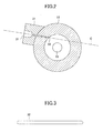
- FIG. 2 is a cross-sectional view of a cylinder 11 of the injection molding machine 10 according to the first embodiment.
- FIG. 2 illustrates a cross-sectional view of the cylinder 11 cut along a plane perpendicular to the axial direction of the cylinder 11.
- FIG. 2 an illustration of a flight 16, which is illustrated in FIG. 1 , is omitted for the purpose of simplifying the drawing.
- FIG. 3 illustrates a supply port 32 for supplying a heating medium that is formed at the inner wall of the cylinder 11 of the injection molding machine 10 according to the first embodiment.
- the injection molding machine 10 includes the cylinder 11 into which a molding material (e.g., resin pellets) is supplied, an injection nozzle 12 that is arranged at the font end of the cylinder 12, a screw 13 that is arranged to be rotatable and movable back and forth within the cylinder 11, and a drive unit 14 that is arranged at the rear side of the cylinder 11.
- the drive unit 14 includes a plasticizing motor for rotating the screw 13 and an injection motor for moving the screw 13 back and forth.
- the screw 13 is arranged to be rotatable and movable back and forth within the cylinder 11.
- the screw 13 includes a rotational shaft 15 and a flight 16.
- the rotational shaft 15 is arranged to be substantially coaxial with the cylinder 11.
- the flight 16 is arranged spirally around the rotational shaft 15.
- a spiral groove 17 is formed along the flight 16.
- the screw 13 is divided into a supply part 13a, a compression part 13b, and a metering part 13c along the axial direction from the rear side (hopper 19 side) to the front side (injection nozzle 12 side).
- the supply part 13a is where the resin is received and transported forward.
- the compression part 13b is where the supplied resin is compressed and melted.
- the metering part 13c is where the molten resin is plasticized at predetermined amounts.
- the depth of the groove 17 of the screw 13 is arranged to be relatively deep at the supply part 13a, relatively shallow at the metering part 13c, and is arranged to become increasingly shallower toward the front side at the compression part 13b.
- the configuration of the screw 13 used in the present invention is not particularly limited to the above example.
- the depth of the groove 17 of the screw 13 may be fixed, or the screw compression ratio may be fixed.
- a resin supply port 18 as a molding material supply port is formed at the rear part of the cylinder 11, and resin is supplied to the cylinder 11 from a hopper 19 via the resin supply port 18.
- a cooler 20 is arranged at the rear part of the cylinder 11 in order to prevent the resin from melting around the resin supply port 18.
- the cooler 20 may be a water-cooling jacket, for example.
- a supply unit that is capable of adjusting the amount of resin supplied may be used instead of the hopper 19.
- a nozzle part 31 as an embodiment of a supply part for supplying a heating medium is arranged at the cylinder 11.
- the heating medium supplied to the cylinder 11 by the nozzle part 31 is for heating the resin within the cylinder 11 and may be a gas, a liquid, or a combination thereof. Because the heating medium comes into direct contact with the resin accommodated within the cylinder 11, the heating efficiency for heating the resin may be improved.
- the temperature gradient of the resin in the axial direction of the cylinder 11 may be raised so that the overall length of the cylinder 11 may be reduced, for example.
- the heating medium comes into direct contact with the resin inside the cylinder 11, temperature control of the resin may be facilitated, the time required for stabilizing the resin temperature may be reduced, and thermal degradation of the resin may be prevented. Further, the heating medium may also be used to transport gas that is generated when the resin is melted outside the cylinder 11.
- the heating medium supplied to the cylinder 11 comes into contact with the inner wall of the cylinder 11 and the surface of the screw 13 and heats both the cylinder 11 and the screw 13 substantially at the same time.
- the space between the inner wall of the cylinder 11 and the flight 16 of the screw 13 may be less likely to change so that the screw 13 may be easily pushed into and pulled out of the cylinder 11.
- the cylinder 11 may not have to be heated to increase the diameter of the cylinder 11 upon pushing/pulling the screw 13 into/out of the cylinder 11.
- the nozzle part 31 may be a continuous opening formed through the cylinder 11 and a nozzle block 21, for example.
- the nozzle block 21 is fixed to the cylinder 11 in the example illustrated in FIG. 2 .
- the nozzle block 21 may be omitted and the nozzle part 31 may be an opening formed through the cylinder 11.
- the nozzle part 31 of the present embodiment is arranged into an opening formed at the cylinder 11, in other embodiments, the nozzle part 31 may be a separate tubular structure that is inserted through a hole formed at the cylinder 11, for example.
- the nozzle part 31 is preferably arranged at the front side of the cooler 20 in order to improve the heating efficiency. Also, the nozzle part 31 may preferably be arranged at the rear side of a resin melting start position at which the resin starts melting. Because resin is not yet melted at the rear side of the resin melting start position, the heating medium may flow more easily through gaps between the resin.
- a supply port (ejection port) 32 of the nozzle part 31 is formed at the inner wall of the cylinder 11. As illustrated in FIGS. 1-3 , the supply port 32 of the nozzle part 31 may be arranged into an elongated shape extending in the axial direction of the screw 13. The flow of the heating medium supplied from the nozzle part 13 into the groove 17 may be arranged to be relatively wide so as to reduce the space within the groove 17 that may allow generation of a vortex flow. In this way, the heating medium may flow easily along the flight 16.
- the supply port 32 of the nozzle part 31 is arranged into an elongated shape extending in the axial direction of the screw 13 in the present embodiment, the supply port 32 may alternatively be arranged into an elongated shape extending in a diagonal direction with respect to the axial direction of the screw 13.
- the supply port 32 of the nozzle part 31 may be arranged into an elongated shape extending in any direction that is perpendicular to the spiral fight 16. In this way, the heating medium may easily flow along the flight 16.
- the shape of the supply port 32 of the nozzle part 31 is not limited to a particular shape and may be rectangular or oval, for example.
- a length L of the supply port 32 in the screw axial direction may be arranged to be longer than a pitch P of the flight 16 in the screw axial direction (see FIG. 1 ).
- the width of the mainstream of the heating medium supplied to the groove 17 from the nozzle part 31 may be at least half the width W of the groove 17 in the screw axial direction (see FIG. 1 ) regardless of the position of the screw 13 with respect to the cylinder 11. As a result, generation of a vortex flow may be prevented.
- a center line C of the nozzle part 31 may deviate from the axis of the rotational shaft 15 of the screw 13 in cross-sectional view.
- the heating medium ejected from the nozzle part 31 may be prevented from diverging to flow in two different directions, for example. That is, the heating medium may be arranged to flow in one direction along the spiral flight 16.
- the center line C of the nozzle part 31 may not be tangential with the inner wall of the cylinder 11 in cross-sectional view and may intersect with the inner wall of the cylinder 11 twice. In this way, the heating medium ejected from the nozzle part 31 may be prevented from entering the small space between the inner wall of the cylinder 11 and the flight 16 of the screw 13 so that the heating medium may flow in one direction along the flight 16.
- the temperature of the heating medium ejected from the nozzle part 13 is preferably arranged to be lower than the temperature of the resin in order to prevent the nozzle part 31 from getting clogged with molten resin.
- the resin is heated and melted by the heating medium and a heater H, which is described below.
- the cylinder 11 includes a discharge hole 33 as an embodiment of a discharge part for discharging the heating medium within the cylinder 11 outside the cylinder.
- the heating medium discharged outside the cylinder 11 may be a gas, a liquid, or a combination thereof.
- the discharge hole 33 is not particularly limited, the discharge hole 33 is preferably arranged at the rear side of the resin melting start position of the cylinder 11 so that the heating medium may easily flow within the cylinder 11.
- the heater H for heating the cylinder 11 may be arranged at the front side of the resin melting start position.
- the heater H is arranged to surround the outer periphery of the cylinder 11 and is configured to heat the cylinder 11 so that the resin within the cylinder 11 may be heated.
- the discharge hole 33 may be arranged at the rear side of the nozzle part 31. As the heating medium ejected from the nozzle part 31 flows toward the rear side, the heat of the heating medium is transferred to the resin, the cylinder 11, and the screw 13, and the heating medium is gradually cooled as a result. The temperature of the cylinder 11 tends to be cooler toward the rear side so that heat that needs to be absorbed by the cooler 20 may be reduced and heating efficiency may be improved.
- the discharge hole 33 may be arranged at the front side of the cooler 20 in order to improve the heating efficiency.
- the heating medium hardly comes into contact with the rear part of the cylinder 11 upon being discharged outside the cylinder 11.
- the temperature at the rear part of the cylinder 11 may easily decrease and excess heat to be absorbed by the cooler 20 may be reduced so that the heating efficiency may be improved.
- the heating medium discharged from the discharge hole 33 is collected in a recovery tank 45 and cooled at the recovery tank 45.
- the heating medium collected in the recovery tank 45 e.g., water
- a heater e.g., steam generator 41 of FIG. 1
- the nozzle part 31 may supply superheated steam as the heating medium for heating the resin within the cylinder 11. Because superheated steam is generated by heating saturated vapor and is therefore dry, the resin may be dried by the superheated steam. Also, because superheated steam hardly includes any oxygen gas, oxidization of the resin may be prevented.
- the steam generator 41 may generate steam by heating water. Then, the steam generated by the steam generator 41 may be heated further by a superheated steam generator 42 to generate superheated steam. The superheated steam generated by the superheated steam generator 42 may then be supplied to the cylinder 11 via the nozzle part 31.
- the air pressure within the cylinder 11 is arranged to be at atmospheric pressure. However, the air pressure of the cylinder 11 may alternatively be arranged to be lower or higher than the atmospheric pressure.
- the steam generator 41 may be a boiler, for example, that is configured to generate steam by heating liquid water.
- the steam generator 41 may be a part of the injection molding machine 10 or may be a separate unit from the injection molding machine 10.
- the steam generator 41 may be a part of a molding product manufacturing plant facility.
- Components such as a depressurizing valve 43 and a flow rate adjustment valve 44 may be arranged at intermediate points of a piping interconnecting the steam generator 41 and the superheated steam generator 42.
- the superheated steam generator 42 as an embodiment of a heater for heating the heating medium to be supplied to the cylinder 11 may heat the steam generated by the steam generator 41 using a heater to generate superheated steam, for example.
- the superheated steam generator 42 may be arranged at the injection molding machine 10, for example.
- At least a part of the superheated steam may change phase from gas to liquid within the cylinder 11.
- resin may be heated by the condensation heat that is emitted when gas is condensed into liquid. Because the condensation heat of water is relatively large, desirably high heat transfer efficiency may be achieved in this case. The condensation heat transfer occurs around a point where the temperature of gas is near the condensation point.
- the axial direction of the cylinder 11 is arranged to be horizontal in the present embodiment, in the case where at least a part of the superheated steam within the cylinder 11 changes phase from gas to liquid, the axial direction of the cylinder 11 may alternatively be diagonal with respect to the horizontal direction, and the discharge hole 33 arranged at the rear side of the nozzle part 31 may be arranged at a lower position than the nozzle part 31. In this case, the superheated steam that is converted into water within the cylinder 11 may be easily discharged from the cylinder 11 so that water may be prevented from accumulating within the cylinder 11.
- the heating medium that is discharged from the cylinder 11 at a high temperature is collected in the recovery tank 45 to be cooled at the recovery tank 45.
- a reflux part is arranged to prompt at least a part of the heating medium discharged outside the cylinder 11 to flow back to the superheated steam generator 42 corresponding to the heater that heats the heating medium to be supplied to the cylinder 11.
- FIG. 4 illustrates an exemplary configuration of an injection molding machine 110 according to the second embodiment.
- the injection molding machine 110 includes an ejector 50 that arranges at least a part of the heating medium discharged outside the cylinder 11 to flow back to the superheated steam generator 42 corresponding to the heater for heating the heating medium to be supplied to the cylinder 11.
- the ejector 50 is an embodiment of the reflux part for returning the heating medium back to the heater.
- the ejector 50 may return at least a part of the heating medium discharged outside the cylinder 11 back to the superheated steam generator 42 at a temperature that is higher than room temperature.
- the ejector 50 includes an ejector nozzle 51, a suction chamber 52, and a diffuser 53.
- the ejector nozzle 51 ejects the steam supplied from the steam generator 41 into the suction chamber 52 to thereby generate suction force for suctioning the steam within the cylinder 11 into the suction chamber 52.
- at least a part of the steam suctioned into the suction chamber 52 may flow back to the superheated steam generator 42 via the diffuser 53 along with the steam ejected from the ejector nozzle 51 to be reheated by the superheated steam generator 42 and re-supplied to the cylinder 11 via the nozzle part 31.
- the heating medium discharged outside the discharge hole 33 may include both steam (vaporized water) and liquid water.
- the liquid water accommodated within the cylinder 11 may be suctioned into the suction chamber 52 along with steam. In this way, liquid water may be prevented from accumulating within the cylinder 11.
- the suction chamber 52 may include a discharge outlet for discharging liquid water, for example.
- the liquid water discharged from the discharge outlet may be transported to the recovery tank 45 along with steam to be cooled at the recovery tank 45.
- the ejector 50 of the present embodiment is configured to transport water that is warmer than room temperature to the recovery tank 45, in alternative embodiments, the water may be transported to the steam generator 41.
- the steam generator 41 may heat the water to generate steam so that heating efficiency may be further improved, for example.
- the reflux part is not limited to a particular configuration.
- a sirocco fan may be used as the reflux part.
- the sirocco fan may be configured to suction the steam accommodated within the cylinder 11 and transport the suctioned steam to a flow path for supplying steam generated by the steam generator 41 to the superheated steam generator 42, for example.
- the high-temperature heating medium discharged outside the cylinder 11 is collected in the recovery tank 45 to be cooled at the recovery tank 45.
- a heat exchange part is arranged for heating the heating medium to be supplied to the cylinder 11 using the heating medium discharged from the cylinder 11.
- FIG. 5 illustrates an exemplary configuration of an injection molding machine 210 according to the third embodiment.
- the injection molding machine 210 includes a heat exchange part 60 that is configured to heat the heating medium to be supplied to the cylinder using the heating medium discharged from the cylinder 11.
- a heat exchange part 60 that is configured to heat the heating medium to be supplied to the cylinder using the heating medium discharged from the cylinder 11.
- the heat exchange part 60 may include a first heat exchange path 61 and a second heat exchange path 62.
- the first heat exchange path 61 is arranged at an intermediate point of a flow path for supplying the steam generated by the steam generator 41 to the superheated steam generator 42.
- the second heat exchange path 62 is arranged at an intermediate point of a flow path for supplying the heating medium (e.g., steam and/or liquid water) discharged outside the cylinder 11 to the recovery tank 45.
- the heating medium e.g., steam and/or liquid water
- the first heat exchange path 61 and the second heat exchange path 62 are arranged to be adjacent to one another so that the heat of the heating medium (e.g., steam) flowing though the second heat exchange path 62 may be transferred to the heating medium (e.g., steam) flowing through the first heat exchange path 61.
- the heating medium e.g., steam
- heating efficiency may be improved, for example.
- the heat exchange part 60 of the above illustrated embodiment is configured to heat the heating medium (e.g., steam) being supplied from the steam generator 41 to the superheated steam generator 42
- the heat exchange part 60 may alternatively be arranged to heat the liquid water within the steam generator 41, for example.
- the heat exchange part 60 of the third embodiment may be used in combination with the reflux part of the second embodiment.
- the reflux part may be configured to return a portion of the heating medium discharged outside the cylinder 11 to the superheated steam generator 42, and the heat exchange part 60 may be configured to use the heat of the remaining portion of the heating medium discharged outside the cylinder 11 to heat the heating medium to be supplied to the cylinder 11.
- the nozzle part 31 in the above illustrated embodiments supplies superheated steam as the heating medium for heating the resin within the cylinder 11
- the type of heating medium used is not limited to superheated steam. That is, any suitable type of heating medium may be selectively used according to the type of resin used.
- an inert gas such as nitrogen gas or argon gas may be used as the heating medium.
- the nozzle part 31 in the above illustrated embodiments supplies superheated steam to the cylinder 11 as the heating medium that changes phase from gas to liquid within the cylinder 11
- a halogenated compound gas, an ionic compound gas, or a glycol compound gas may be supplied to the cylinder 11 instead of superheated steam, for example. At least a part of these gases may also change phase from gas to liquid within the cylinder 11.
- the nozzle part 31 in the above illustrated embodiments supplies a heating medium for heating resin to the cylinder 11
- the nozzle part 31 may alternatively be used to supply a cooling medium for cooling the cylinder 11 in a case of cooling the cylinder 11 for maintenance purposes, for example.
- the nozzle part 31 in the above illustrated embodiments is arranged at the cylinder 11 of a screw in-line type injection unit
- the nozzle part 31 may alternatively be arranged at a cylinder of a screw pre-plasticizing type injection unit, for example.
- the screw pre-plasticizing type injection unit supplies resin melted at a plasticizing cylinder to an injection cylinder and injects the molten resin from the injection cylinder into a mold unit.
- the nozzle part 31 may be arranged at either one or both of the plasticizing cylinder and the injection cylinder.
- the nozzle part 31 is preferably arranged at the plasticizing cylinder where gas could flow more easily, for example.
- a cylinder of an injection molding machine may include more than one of the nozzle parts 31 and/or more than one of the discharge holes 33, for example.
Landscapes
- Engineering & Computer Science (AREA)
- Manufacturing & Machinery (AREA)
- Mechanical Engineering (AREA)
- Injection Moulding Of Plastics Or The Like (AREA)
Abstract
Description
- The present invention relates to an injection molding machine and an injection molding method.
- Injection molding machines include a cylinder into which a molding material (e.g., resin pellets) is supplied, a screw that is arranged to be rotatable and movable back and forth within the cylinder, and a band heater surrounding the outer periphery of the cylinder (See e.g., Japanese Unexamined Patent Publication No.
2009-137083 - In conventional injection molding machines, the heating efficiency for heating the molding material is rather low because the cylinder is arranged between the band heater, which is the heat source, and the molding material.
- It is an object of at least one embodiment of the present invention to provide an injection molding machine with improved heating efficiency for heating the molding material.
- In one embodiment of the present invention, an injection molding machine includes a cylinder into which a molding material is supplied. The cylinder includes a supply part the supplies a heating medium into the cylinder to heat the molding material.
- According to an aspect of the present invention, an injection molding machine with improved heating efficiency for heating the molding material may be provided.
-
-
FIG. 1 illustrates an exemplary configuration of an injection molding machine according to a first embodiment of the present invention; -
FIG. 2 is a cross-sectional view of a cylinder of the injection molding machine according to the first embodiment; -
FIG. 3 illustrates a supply port for supplying a heating medium that is arranged at the inner wall of the cylinder of the injection molding machine according to the first embodiment; -
FIG. 4 illustrates an exemplary configuration of an injection molding machine according to a second embodiment of the present invention; and -
FIG. 5 illustrates an exemplary configuration of an injection molding machine according to a third embodiment of the present invention. - In the following, embodiments of the present invention are described with reference to the accompanying drawings. It is noted that identical or corresponding features illustrated in more than one of the drawings may be identified by the same reference numerals and their descriptions may be omitted. Also, in the following descriptions, it is assumed that a resin injection direction corresponds to a forward direction and the direction opposite the resin injection direction corresponds to a backward direction.
-
FIG. 1 illustrates an exemplary configuration of aninjection molding machine 10 according to a first embodiment of the present invention. Note that inFIG. 1 , an illustration of anozzle block 21, which is illustrated inFIG. 2 , is omitted.FIG. 2 is a cross-sectional view of acylinder 11 of theinjection molding machine 10 according to the first embodiment.FIG. 2 illustrates a cross-sectional view of thecylinder 11 cut along a plane perpendicular to the axial direction of thecylinder 11. Note that inFIG. 2 , an illustration of aflight 16, which is illustrated inFIG. 1 , is omitted for the purpose of simplifying the drawing.FIG. 3 illustrates asupply port 32 for supplying a heating medium that is formed at the inner wall of thecylinder 11 of theinjection molding machine 10 according to the first embodiment. - The
injection molding machine 10 includes thecylinder 11 into which a molding material (e.g., resin pellets) is supplied, aninjection nozzle 12 that is arranged at the font end of thecylinder 12, ascrew 13 that is arranged to be rotatable and movable back and forth within thecylinder 11, and adrive unit 14 that is arranged at the rear side of thecylinder 11. Thedrive unit 14 includes a plasticizing motor for rotating thescrew 13 and an injection motor for moving thescrew 13 back and forth. - The
screw 13 is arranged to be rotatable and movable back and forth within thecylinder 11. Thescrew 13 includes arotational shaft 15 and aflight 16. Therotational shaft 15 is arranged to be substantially coaxial with thecylinder 11. Theflight 16 is arranged spirally around therotational shaft 15. Aspiral groove 17 is formed along theflight 16. When thescrew 13 rotates, theflight 16 moves, and resin supplied to thegroove 17 is transported forward. - The
screw 13 is divided into asupply part 13a, acompression part 13b, and ametering part 13c along the axial direction from the rear side (hopper 19 side) to the front side (injection nozzle 12 side). Thesupply part 13a is where the resin is received and transported forward. Thecompression part 13b is where the supplied resin is compressed and melted. Themetering part 13c is where the molten resin is plasticized at predetermined amounts. The depth of thegroove 17 of thescrew 13 is arranged to be relatively deep at thesupply part 13a, relatively shallow at themetering part 13c, and is arranged to become increasingly shallower toward the front side at thecompression part 13b. - Note that the configuration of the
screw 13 used in the present invention is not particularly limited to the above example. In other examples, the depth of thegroove 17 of thescrew 13 may be fixed, or the screw compression ratio may be fixed. - A
resin supply port 18 as a molding material supply port is formed at the rear part of thecylinder 11, and resin is supplied to thecylinder 11 from ahopper 19 via theresin supply port 18. Acooler 20 is arranged at the rear part of thecylinder 11 in order to prevent the resin from melting around theresin supply port 18. The cooler 20 may be a water-cooling jacket, for example. - Note that although the
hopper 19 for supplying resin to thecylinder 11 is arranged at the rear part of thecylinder 11 in the present embodiment, in other embodiments, a supply unit that is capable of adjusting the amount of resin supplied may be used instead of thehopper 19. - In the following, operations of the
injection molding machine 10 are described. - When the plasticizing motor of the
drive unit 14 is driven and thescrew 13 is rotated, resin supplied to thecylinder 11 via theresin supply port 18 is transported forward and melted. The molten resin is transported toward the front side of thescrew 13. As the resin accumulates at the front side of thescrew 13, thecrew 13 recedes toward the rear side. When a predetermined amount of resin is accumulated at the front side of thescrew 13, rotation of thescrew 13 is stopped. - Then, when the injection motor of the
drive unit 14 is driven to move thescrew 13 forward, the resin accumulated at the front side of thescrew 13 is ejected from theinjection nozzle 12 and filled into a cavity of a mold unit. The molten resin filled into the cavity is then solidified to form a molding product. - In the following, ways in which the resin within the
cylinder 11 may be heated are described. - As illustrated in
FIG. 1 , in order to improve the heating efficiency for heating the resin within thecylinder 11, anozzle part 31 as an embodiment of a supply part for supplying a heating medium is arranged at thecylinder 11. The heating medium supplied to thecylinder 11 by thenozzle part 31 is for heating the resin within thecylinder 11 and may be a gas, a liquid, or a combination thereof. Because the heating medium comes into direct contact with the resin accommodated within thecylinder 11, the heating efficiency for heating the resin may be improved. By improving the heating efficiency for heating the resin, the temperature gradient of the resin in the axial direction of thecylinder 11 may be raised so that the overall length of thecylinder 11 may be reduced, for example. Also, because the heating medium comes into direct contact with the resin inside thecylinder 11, temperature control of the resin may be facilitated, the time required for stabilizing the resin temperature may be reduced, and thermal degradation of the resin may be prevented. Further, the heating medium may also be used to transport gas that is generated when the resin is melted outside thecylinder 11. - The heating medium supplied to the
cylinder 11 comes into contact with the inner wall of thecylinder 11 and the surface of thescrew 13 and heats both thecylinder 11 and thescrew 13 substantially at the same time. Thus, the space between the inner wall of thecylinder 11 and theflight 16 of thescrew 13 may be less likely to change so that thescrew 13 may be easily pushed into and pulled out of thecylinder 11. Also, in the present embodiment, thecylinder 11 may not have to be heated to increase the diameter of thecylinder 11 upon pushing/pulling thescrew 13 into/out of thecylinder 11. - As illustrated in
FIG.2 , thenozzle part 31 may be a continuous opening formed through thecylinder 11 and anozzle block 21, for example. Thenozzle block 21 is fixed to thecylinder 11 in the example illustrated inFIG. 2 . Note that in alternative embodiments, thenozzle block 21 may be omitted and thenozzle part 31 may be an opening formed through thecylinder 11. - Also, although the
nozzle part 31 of the present embodiment is arranged into an opening formed at thecylinder 11, in other embodiments, thenozzle part 31 may be a separate tubular structure that is inserted through a hole formed at thecylinder 11, for example. - Although the position of the
nozzle part 31 is not particularly limited, thenozzle part 31 is preferably arranged at the front side of the cooler 20 in order to improve the heating efficiency. Also, thenozzle part 31 may preferably be arranged at the rear side of a resin melting start position at which the resin starts melting. Because resin is not yet melted at the rear side of the resin melting start position, the heating medium may flow more easily through gaps between the resin. - A supply port (ejection port) 32 of the
nozzle part 31 is formed at the inner wall of thecylinder 11. As illustrated inFIGS. 1-3 , thesupply port 32 of thenozzle part 31 may be arranged into an elongated shape extending in the axial direction of thescrew 13. The flow of the heating medium supplied from thenozzle part 13 into thegroove 17 may be arranged to be relatively wide so as to reduce the space within thegroove 17 that may allow generation of a vortex flow. In this way, the heating medium may flow easily along theflight 16. - Note that although the
supply port 32 of thenozzle part 31 is arranged into an elongated shape extending in the axial direction of thescrew 13 in the present embodiment, thesupply port 32 may alternatively be arranged into an elongated shape extending in a diagonal direction with respect to the axial direction of thescrew 13. For example, thesupply port 32 of thenozzle part 31 may be arranged into an elongated shape extending in any direction that is perpendicular to thespiral fight 16. In this way, the heating medium may easily flow along theflight 16. Note that the shape of thesupply port 32 of thenozzle part 31 is not limited to a particular shape and may be rectangular or oval, for example. - A length L of the
supply port 32 in the screw axial direction (seeFIG. 1 ) may be arranged to be longer than a pitch P of theflight 16 in the screw axial direction (seeFIG. 1 ). In this way, the width of the mainstream of the heating medium supplied to thegroove 17 from thenozzle part 31 may be at least half the width W of thegroove 17 in the screw axial direction (seeFIG. 1 ) regardless of the position of thescrew 13 with respect to thecylinder 11. As a result, generation of a vortex flow may be prevented. - As illustrated in
FIG. 2 , a center line C of thenozzle part 31 may deviate from the axis of therotational shaft 15 of thescrew 13 in cross-sectional view. In this way, the heating medium ejected from thenozzle part 31 may be prevented from diverging to flow in two different directions, for example. That is, the heating medium may be arranged to flow in one direction along thespiral flight 16. - As illustrated in
FIG. 2 , the center line C of thenozzle part 31 may not be tangential with the inner wall of thecylinder 11 in cross-sectional view and may intersect with the inner wall of thecylinder 11 twice. In this way, the heating medium ejected from thenozzle part 31 may be prevented from entering the small space between the inner wall of thecylinder 11 and theflight 16 of thescrew 13 so that the heating medium may flow in one direction along theflight 16. - The temperature of the heating medium ejected from the
nozzle part 13 is preferably arranged to be lower than the temperature of the resin in order to prevent thenozzle part 31 from getting clogged with molten resin. In this case, the resin is heated and melted by the heating medium and a heater H, which is described below. - As illustrated in
FIG. 1 , thecylinder 11 includes adischarge hole 33 as an embodiment of a discharge part for discharging the heating medium within thecylinder 11 outside the cylinder. The heating medium discharged outside thecylinder 11 may be a gas, a liquid, or a combination thereof. - Although the position of the
discharge hole 33 is not particularly limited, thedischarge hole 33 is preferably arranged at the rear side of the resin melting start position of thecylinder 11 so that the heating medium may easily flow within thecylinder 11. - In the case where both the
discharge hole 33 and thenozzle part 31 are arranged at the rear side of the resin melting start position of thecylinder 11, the heater H for heating thecylinder 11 may be arranged at the front side of the resin melting start position. The heater H is arranged to surround the outer periphery of thecylinder 11 and is configured to heat thecylinder 11 so that the resin within thecylinder 11 may be heated. - The
discharge hole 33 may be arranged at the rear side of thenozzle part 31. As the heating medium ejected from thenozzle part 31 flows toward the rear side, the heat of the heating medium is transferred to the resin, thecylinder 11, and thescrew 13, and the heating medium is gradually cooled as a result. The temperature of thecylinder 11 tends to be cooler toward the rear side so that heat that needs to be absorbed by the cooler 20 may be reduced and heating efficiency may be improved. - The
discharge hole 33 may be arranged at the front side of the cooler 20 in order to improve the heating efficiency. In this case, the heating medium hardly comes into contact with the rear part of thecylinder 11 upon being discharged outside thecylinder 11. Thus, the temperature at the rear part of thecylinder 11 may easily decrease and excess heat to be absorbed by the cooler 20 may be reduced so that the heating efficiency may be improved. - The heating medium discharged from the
discharge hole 33 is collected in arecovery tank 45 and cooled at therecovery tank 45. The heating medium collected in the recovery tank 45 (e.g., water) may be transported to a heater (e.g.,steam generator 41 ofFIG. 1 ) so that the heating medium may be reheated, for example. - In one embodiment, the
nozzle part 31 may supply superheated steam as the heating medium for heating the resin within thecylinder 11. Because superheated steam is generated by heating saturated vapor and is therefore dry, the resin may be dried by the superheated steam. Also, because superheated steam hardly includes any oxygen gas, oxidization of the resin may be prevented. - The
steam generator 41 may generate steam by heating water. Then, the steam generated by thesteam generator 41 may be heated further by asuperheated steam generator 42 to generate superheated steam. The superheated steam generated by thesuperheated steam generator 42 may then be supplied to thecylinder 11 via thenozzle part 31. In the present embodiment, the air pressure within thecylinder 11 is arranged to be at atmospheric pressure. However, the air pressure of thecylinder 11 may alternatively be arranged to be lower or higher than the atmospheric pressure. - The
steam generator 41 may be a boiler, for example, that is configured to generate steam by heating liquid water. Thesteam generator 41 may be a part of theinjection molding machine 10 or may be a separate unit from theinjection molding machine 10. For example, thesteam generator 41 may be a part of a molding product manufacturing plant facility. Components such as a depressurizingvalve 43 and a flowrate adjustment valve 44 may be arranged at intermediate points of a piping interconnecting thesteam generator 41 and thesuperheated steam generator 42. - The
superheated steam generator 42 as an embodiment of a heater for heating the heating medium to be supplied to thecylinder 11 may heat the steam generated by thesteam generator 41 using a heater to generate superheated steam, for example. Thesuperheated steam generator 42 may be arranged at theinjection molding machine 10, for example. - At least a part of the superheated steam may change phase from gas to liquid within the
cylinder 11. In this case, resin may be heated by the condensation heat that is emitted when gas is condensed into liquid. Because the condensation heat of water is relatively large, desirably high heat transfer efficiency may be achieved in this case. The condensation heat transfer occurs around a point where the temperature of gas is near the condensation point. - Note that although the axial direction of the
cylinder 11 is arranged to be horizontal in the present embodiment, in the case where at least a part of the superheated steam within thecylinder 11 changes phase from gas to liquid, the axial direction of thecylinder 11 may alternatively be diagonal with respect to the horizontal direction, and thedischarge hole 33 arranged at the rear side of thenozzle part 31 may be arranged at a lower position than thenozzle part 31. In this case, the superheated steam that is converted into water within thecylinder 11 may be easily discharged from thecylinder 11 so that water may be prevented from accumulating within thecylinder 11. - In the above first embodiment, the heating medium that is discharged from the
cylinder 11 at a high temperature is collected in therecovery tank 45 to be cooled at therecovery tank 45. - In a second embodiment of the present invention, in order to improve heating efficiency, a reflux part is arranged to prompt at least a part of the heating medium discharged outside the
cylinder 11 to flow back to thesuperheated steam generator 42 corresponding to the heater that heats the heating medium to be supplied to thecylinder 11. In the following, features of the present embodiment that differ from those of the first embodiment are described. -
FIG. 4 illustrates an exemplary configuration of aninjection molding machine 110 according to the second embodiment. InFIG. 4 , theinjection molding machine 110 includes anejector 50 that arranges at least a part of the heating medium discharged outside thecylinder 11 to flow back to thesuperheated steam generator 42 corresponding to the heater for heating the heating medium to be supplied to thecylinder 11. Theejector 50 is an embodiment of the reflux part for returning the heating medium back to the heater. Theejector 50 may return at least a part of the heating medium discharged outside thecylinder 11 back to thesuperheated steam generator 42 at a temperature that is higher than room temperature. - The
ejector 50 includes anejector nozzle 51, asuction chamber 52, and adiffuser 53. Theejector nozzle 51 ejects the steam supplied from thesteam generator 41 into thesuction chamber 52 to thereby generate suction force for suctioning the steam within thecylinder 11 into thesuction chamber 52. In this way, at least a part of the steam suctioned into thesuction chamber 52 may flow back to thesuperheated steam generator 42 via thediffuser 53 along with the steam ejected from theejector nozzle 51 to be reheated by thesuperheated steam generator 42 and re-supplied to thecylinder 11 via thenozzle part 31. - In the case where at least a part of the superheated steam supplied to the
cylinder 11 via thenozzle part 31 changes phase from gas to liquid inside thecylinder 11, the heating medium discharged outside thedischarge hole 33 may include both steam (vaporized water) and liquid water. - In the above case, when suctioning the heating medium into the
suction chamber 52, the liquid water accommodated within thecylinder 11 may be suctioned into thesuction chamber 52 along with steam. In this way, liquid water may be prevented from accumulating within thecylinder 11. - The
suction chamber 52 may include a discharge outlet for discharging liquid water, for example. The liquid water discharged from the discharge outlet may be transported to therecovery tank 45 along with steam to be cooled at therecovery tank 45. - Of the steam that has been suctioned into the
suction chamber 52, a large portion thereof may be flown back to thesuperheated steam generator 42 while a remaining portion of the steam may be transported to therecovery tank 45. - Note that although the
ejector 50 of the present embodiment is configured to transport water that is warmer than room temperature to therecovery tank 45, in alternative embodiments, the water may be transported to thesteam generator 41. In this case, thesteam generator 41 may heat the water to generate steam so that heating efficiency may be further improved, for example. - Also, although the
ejector 50 is used as the reflux part in the present embodiment, the reflux part is not limited to a particular configuration. For example, a sirocco fan may be used as the reflux part. In this case, the sirocco fan may be configured to suction the steam accommodated within thecylinder 11 and transport the suctioned steam to a flow path for supplying steam generated by thesteam generator 41 to thesuperheated steam generator 42, for example. - In the above first embodiment, the high-temperature heating medium discharged outside the
cylinder 11 is collected in therecovery tank 45 to be cooled at therecovery tank 45. - In a third embodiment of the present invention, to improve heating efficiency, a heat exchange part is arranged for heating the heating medium to be supplied to the
cylinder 11 using the heating medium discharged from thecylinder 11. In the following, features of the third embodiment that differ from those of the first embodiment are described. -
FIG. 5 illustrates an exemplary configuration of aninjection molding machine 210 according to the third embodiment. InFIG. 5 , theinjection molding machine 210 includes aheat exchange part 60 that is configured to heat the heating medium to be supplied to the cylinder using the heating medium discharged from thecylinder 11. By using the heat of the heating medium discharged from thecylinder 11 to heat the heating medium to be supplied to thecylinder 11, heating efficiency may be improved for heating the resin within thecylinder 11 and energy resources may be conserved, for example. - As illustrated in
FIG. 5 , theheat exchange part 60 may include a firstheat exchange path 61 and a secondheat exchange path 62. The firstheat exchange path 61 is arranged at an intermediate point of a flow path for supplying the steam generated by thesteam generator 41 to thesuperheated steam generator 42. The secondheat exchange path 62 is arranged at an intermediate point of a flow path for supplying the heating medium (e.g., steam and/or liquid water) discharged outside thecylinder 11 to therecovery tank 45. The firstheat exchange path 61 and the secondheat exchange path 62 are arranged to be adjacent to one another so that the heat of the heating medium (e.g., steam) flowing though the secondheat exchange path 62 may be transferred to the heating medium (e.g., steam) flowing through the firstheat exchange path 61. By heating the heating medium (e.g., steam) to be supplied to thecylinder 11 using the heat of the heating medium (e.g., steam) discharged outside thecylinder 11, heating efficiency may be improved, for example. - Note that although the
heat exchange part 60 of the above illustrated embodiment is configured to heat the heating medium (e.g., steam) being supplied from thesteam generator 41 to thesuperheated steam generator 42, theheat exchange part 60 may alternatively be arranged to heat the liquid water within thesteam generator 41, for example. - Also, in other alternative embodiments, the
heat exchange part 60 of the third embodiment may used in combination with the reflux part of the second embodiment. For example, the reflux part may be configured to return a portion of the heating medium discharged outside thecylinder 11 to thesuperheated steam generator 42, and theheat exchange part 60 may be configured to use the heat of the remaining portion of the heating medium discharged outside thecylinder 11 to heat the heating medium to be supplied to thecylinder 11. - While the injection molding machine of the present invention has been described above by way of illustrative embodiments, the present invention is not limited to these embodiments, and numerous variations and modifications may be made without departing from the scope of the present invention.
- For example, although the
nozzle part 31 in the above illustrated embodiments supplies superheated steam as the heating medium for heating the resin within thecylinder 11, the type of heating medium used is not limited to superheated steam. That is, any suitable type of heating medium may be selectively used according to the type of resin used. For example, in the case where the resin used is easily degraded by water, an inert gas such as nitrogen gas or argon gas may be used as the heating medium. - Also, although the
nozzle part 31 in the above illustrated embodiments supplies superheated steam to thecylinder 11 as the heating medium that changes phase from gas to liquid within thecylinder 11, in alternative embodiments, a halogenated compound gas, an ionic compound gas, or a glycol compound gas may be supplied to thecylinder 11 instead of superheated steam, for example. At least a part of these gases may also change phase from gas to liquid within thecylinder 11. - Also, although the
nozzle part 31 in the above illustrated embodiments supplies a heating medium for heating resin to thecylinder 11, thenozzle part 31 may alternatively be used to supply a cooling medium for cooling thecylinder 11 in a case of cooling thecylinder 11 for maintenance purposes, for example. - Also, although the
nozzle part 31 in the above illustrated embodiments is arranged at thecylinder 11 of a screw in-line type injection unit, thenozzle part 31 may alternatively be arranged at a cylinder of a screw pre-plasticizing type injection unit, for example. The screw pre-plasticizing type injection unit supplies resin melted at a plasticizing cylinder to an injection cylinder and injects the molten resin from the injection cylinder into a mold unit. In the case of arranging thenozzle part 31 at the screw pre-plasticizing type injection unit, thenozzle part 31 may be arranged at either one or both of the plasticizing cylinder and the injection cylinder. In the screw pre-plasticizing type injection unit, thenozzle part 31 is preferably arranged at the plasticizing cylinder where gas could flow more easily, for example. - Also, although the
cylinder 11 in the above illustrated embodiments includes onenozzle part 31 and onedischarge hole 33, in alternative embodiments, a cylinder of an injection molding machine may include more than one of thenozzle parts 31 and/or more than one of the discharge holes 33, for example. - The present application is based on and claims the benefit of priority to Japanese Patent Application No.
2012-244199, filed on November 6, 2012
Claims (9)
- An injection molding machine comprising:a cylinder (11) into which a molding material is supplied;wherein the cylinder includes a supply part (31) that supplies a heating medium into the cylinder to heat the molding material.
- The injection molding machine as claimed in claim 1, wherein
the supply part (31) supplies superheated steam into the cylinder (11) as the heating medium for heating the molding material. - The injection molding machine as claimed in claim 1 or 2, wherein
at least a part of the heating medium supplied into the cylinder by the supply part (31) changes phase from gas to liquid within the cylinder (11). - The injection molding machine as claimed in any one of claims 1-3, wherein
the cylinder (11) includes a discharge part (33) that discharges the heating medium within the cylinder outside the cylinder. - The injection molding machine as claimed in claim 4, wherein
the cylinder includes a cooler (20) for cooling a rear part of the cylinder; and
the discharge part (33) is arranged at a front side of the cooler. - The injection molding machine as claimed in any one of claims 1-5, wherein
the supply part (31) includes a supply port (32) arranged at an inner wall of the cylinder (11) for supplying the heating medium into the cylinder; and
the supply port (32) is arranged into an elongated shape extending in an axial direction of a screw (13), which is arranged within the cylinder, or an elongated shape extending in a diagonal direction with respect to an axial direction of the screw (13). - The injection molding machine as claimed in any one of claims 1-6, further comprising:a heater (42) that heats the heating medium that is to be supplied to the cylinder; anda reflux part (50) that arranges at least a part of the heating medium that is discharged outside the cylinder (11) to return to the heater (42).
- The injection molding machine as claimed in any one of claims 1-7, further comprising:a heat exchange part (60) that heats the heating medium to be supplied to the cylinder (11) using the heating medium discharged outside the cylinder.
- An injection molding method comprising:heating a molding material within a cylinder; andsupplying a heating medium into the cylinder to heat the molding material.
Applications Claiming Priority (1)
| Application Number | Priority Date | Filing Date | Title |
|---|---|---|---|
| JP2012244199A JP5946750B2 (en) | 2012-11-06 | 2012-11-06 | Injection molding machine and injection molding method |
Publications (2)
| Publication Number | Publication Date |
|---|---|
| EP2727703A1 true EP2727703A1 (en) | 2014-05-07 |
| EP2727703B1 EP2727703B1 (en) | 2017-06-14 |
Family
ID=49485594
Family Applications (1)
| Application Number | Title | Priority Date | Filing Date |
|---|---|---|---|
| EP13190258.7A Active EP2727703B1 (en) | 2012-11-06 | 2013-10-25 | Injection molding machine and injection molding method |
Country Status (3)
| Country | Link |
|---|---|
| EP (1) | EP2727703B1 (en) |
| JP (1) | JP5946750B2 (en) |
| CN (1) | CN103802290B (en) |
Families Citing this family (2)
| Publication number | Priority date | Publication date | Assignee | Title |
|---|---|---|---|---|
| CN116490303A (en) * | 2021-03-30 | 2023-07-25 | 住友重机械工业株式会社 | Material preheating device and injection molding machine |
| CN117429023A (en) * | 2023-10-24 | 2024-01-23 | 江阴小乐机电发展有限公司 | Feeding device for injection molding machine |
Citations (8)
| Publication number | Priority date | Publication date | Assignee | Title |
|---|---|---|---|---|
| US2354363A (en) * | 1943-04-23 | 1944-07-25 | Arthur A Burry | Means for heating thermoplastic materials for molding |
| US4158540A (en) * | 1976-07-02 | 1979-06-19 | Gebruder Buhler Ag | Process and apparatus for manufacturing molded parts from granulated plastic materials |
| JPH10151652A (en) * | 1996-11-22 | 1998-06-09 | Ube Ind Ltd | Method and apparatus for heating plasticized material |
| JP2004050415A (en) * | 2002-07-16 | 2004-02-19 | Sumitomo Heavy Ind Ltd | Injection device |
| US20090053348A1 (en) * | 2006-01-23 | 2009-02-26 | Sumitomo Heavy Industries, Ltd. | Injection Apparatus |
| JP2009137083A (en) | 2007-12-04 | 2009-06-25 | Sumitomo Heavy Ind Ltd | Temperature display device for injection molding machine |
| JP2010162716A (en) * | 2009-01-13 | 2010-07-29 | Minoru Kasei Kk | Method and apparatus for plasticizing plastic |
| JP2011110748A (en) * | 2009-11-25 | 2011-06-09 | Yokohama Rubber Co Ltd:The | Method of kneading rubber composition and kneading equipment |
Family Cites Families (7)
| Publication number | Priority date | Publication date | Assignee | Title |
|---|---|---|---|---|
| US3156009A (en) * | 1960-12-30 | 1964-11-10 | Standard Oil Co | Devolatilizing extruder |
| JPS54131788A (en) * | 1978-04-03 | 1979-10-13 | Fujikura Ltd | Method of fabricating rubber or plastic cable |
| JPS5638248A (en) * | 1979-09-06 | 1981-04-13 | Nippon Petrochem Co Ltd | Preparation of air-permeable composite material |
| JPH0752185A (en) * | 1993-08-17 | 1995-02-28 | Kobe Steel Ltd | Molding method and molding apparatus for long-fiber composite material |
| JP2004322438A (en) * | 2003-04-24 | 2004-11-18 | Sodick Co Ltd | Method for plasticizating resin material and plasticization apparatus for method |
| FR2855093B1 (en) * | 2003-05-21 | 2006-06-23 | Air Liquide | PROCESS AND DEVICE FOR PRODUCING POLYETHYLENE TEREPHTHALATE PREFORMS |
| JP5546123B2 (en) * | 2008-12-25 | 2014-07-09 | 株式会社ソディック | Pre-plastic injection device |
-
2012
- 2012-11-06 JP JP2012244199A patent/JP5946750B2/en active Active
-
2013
- 2013-08-09 CN CN201310346528.XA patent/CN103802290B/en active Active
- 2013-10-25 EP EP13190258.7A patent/EP2727703B1/en active Active
Patent Citations (8)
| Publication number | Priority date | Publication date | Assignee | Title |
|---|---|---|---|---|
| US2354363A (en) * | 1943-04-23 | 1944-07-25 | Arthur A Burry | Means for heating thermoplastic materials for molding |
| US4158540A (en) * | 1976-07-02 | 1979-06-19 | Gebruder Buhler Ag | Process and apparatus for manufacturing molded parts from granulated plastic materials |
| JPH10151652A (en) * | 1996-11-22 | 1998-06-09 | Ube Ind Ltd | Method and apparatus for heating plasticized material |
| JP2004050415A (en) * | 2002-07-16 | 2004-02-19 | Sumitomo Heavy Ind Ltd | Injection device |
| US20090053348A1 (en) * | 2006-01-23 | 2009-02-26 | Sumitomo Heavy Industries, Ltd. | Injection Apparatus |
| JP2009137083A (en) | 2007-12-04 | 2009-06-25 | Sumitomo Heavy Ind Ltd | Temperature display device for injection molding machine |
| JP2010162716A (en) * | 2009-01-13 | 2010-07-29 | Minoru Kasei Kk | Method and apparatus for plasticizing plastic |
| JP2011110748A (en) * | 2009-11-25 | 2011-06-09 | Yokohama Rubber Co Ltd:The | Method of kneading rubber composition and kneading equipment |
Also Published As
| Publication number | Publication date |
|---|---|
| CN103802290B (en) | 2017-04-26 |
| EP2727703B1 (en) | 2017-06-14 |
| JP5946750B2 (en) | 2016-07-06 |
| JP2014091292A (en) | 2014-05-19 |
| CN103802290A (en) | 2014-05-21 |
Similar Documents
| Publication | Publication Date | Title |
|---|---|---|
| ES2691807T3 (en) | Injector to fill a mold with plastic particles | |
| CN103953396B (en) | The manufacture method of turbine hollow blade, turbine and correlation | |
| KR101876084B1 (en) | 3d printer for manufaturing food | |
| CN106912198B (en) | Fluid Jet Ejection Equipment | |
| CN104995403A (en) | Rotor blade of a wind turbine | |
| EP2727703B1 (en) | Injection molding machine and injection molding method | |
| CN107801383A (en) | Method and apparatus for cooling extruded profiles | |
| WO2009093710A1 (en) | Screw type kneader | |
| KR101263275B1 (en) | extruder having air cooling means | |
| BR112018004258B1 (en) | SYSTEM FOR COOLING MOLDS FOR METAL OR METAL ALLOYS AND MOLDING SET INCLUDING SUCH COOLING SYSTEM AND AT LEAST ONE MOLD | |
| JP2006258316A (en) | Heating/cooling device | |
| CN108367909A (en) | Fluid forces device including radiator | |
| JP6158059B2 (en) | Injection molding machine | |
| CN107901108A (en) | Plastic products process equipment | |
| CN209079034U (en) | A kind of injection molding apparatus | |
| JP2004322438A (en) | Method for plasticizating resin material and plasticization apparatus for method | |
| JP6087265B2 (en) | Injection molding machine | |
| JP4258771B2 (en) | Underwater granulation method for thermoplastic resin material and die for thermoplastic resin underwater granulation | |
| KR101688204B1 (en) | Melt cooling device for melting light metal casting apparatus using a vacuum | |
| JP2004050415A (en) | Injection device | |
| JP6158102B2 (en) | Injection molding machine | |
| JP6382392B2 (en) | Injection molding machine | |
| JP6121315B2 (en) | Injection molding machine | |
| JP6409019B2 (en) | Moisture percentage adjustment mechanism for injection molding machine, injection molding machine with moisture percentage adjustment function | |
| JP4964655B2 (en) | Evaporative cooling device |
Legal Events
| Date | Code | Title | Description |
|---|---|---|---|
| PUAI | Public reference made under article 153(3) epc to a published international application that has entered the european phase |
Free format text: ORIGINAL CODE: 0009012 |
|
| 17P | Request for examination filed |
Effective date: 20131025 |
|
| AK | Designated contracting states |
Kind code of ref document: A1 Designated state(s): AL AT BE BG CH CY CZ DE DK EE ES FI FR GB GR HR HU IE IS IT LI LT LU LV MC MK MT NL NO PL PT RO RS SE SI SK SM TR |
|
| AX | Request for extension of the european patent |
Extension state: BA ME |
|
| 17P | Request for examination filed |
Effective date: 20141104 |
|
| RBV | Designated contracting states (corrected) |
Designated state(s): AL AT BE BG CH CY CZ DE DK EE ES FI FR GB GR HR HU IE IS IT LI LT LU LV MC MK MT NL NO PL PT RO RS SE SI SK SM TR |
|
| 17Q | First examination report despatched |
Effective date: 20160331 |
|
| GRAP | Despatch of communication of intention to grant a patent |
Free format text: ORIGINAL CODE: EPIDOSNIGR1 |
|
| INTG | Intention to grant announced |
Effective date: 20161124 |
|
| GRAS | Grant fee paid |
Free format text: ORIGINAL CODE: EPIDOSNIGR3 |
|
| RIN1 | Information on inventor provided before grant (corrected) |
Inventor name: ARAKAWA, YOSHIHIKO |
|
| GRAA | (expected) grant |
Free format text: ORIGINAL CODE: 0009210 |
|
| AK | Designated contracting states |
Kind code of ref document: B1 Designated state(s): AL AT BE BG CH CY CZ DE DK EE ES FI FR GB GR HR HU IE IS IT LI LT LU LV MC MK MT NL NO PL PT RO RS SE SI SK SM TR |
|
| REG | Reference to a national code |
Ref country code: GB Ref legal event code: FG4D |
|
| REG | Reference to a national code |
Ref country code: CH Ref legal event code: EP Ref country code: AT Ref legal event code: REF Ref document number: 900534 Country of ref document: AT Kind code of ref document: T Effective date: 20170615 |
|
| REG | Reference to a national code |
Ref country code: IE Ref legal event code: FG4D |
|
| REG | Reference to a national code |
Ref country code: DE Ref legal event code: R096 Ref document number: 602013022176 Country of ref document: DE |
|
| REG | Reference to a national code |
Ref country code: NL Ref legal event code: MP Effective date: 20170614 |
|
| REG | Reference to a national code |
Ref country code: LT Ref legal event code: MG4D |
|
| PG25 | Lapsed in a contracting state [announced via postgrant information from national office to epo] |
Ref country code: FI Free format text: LAPSE BECAUSE OF FAILURE TO SUBMIT A TRANSLATION OF THE DESCRIPTION OR TO PAY THE FEE WITHIN THE PRESCRIBED TIME-LIMIT Effective date: 20170614 Ref country code: NO Free format text: LAPSE BECAUSE OF FAILURE TO SUBMIT A TRANSLATION OF THE DESCRIPTION OR TO PAY THE FEE WITHIN THE PRESCRIBED TIME-LIMIT Effective date: 20170914 Ref country code: HR Free format text: LAPSE BECAUSE OF FAILURE TO SUBMIT A TRANSLATION OF THE DESCRIPTION OR TO PAY THE FEE WITHIN THE PRESCRIBED TIME-LIMIT Effective date: 20170614 Ref country code: LT Free format text: LAPSE BECAUSE OF FAILURE TO SUBMIT A TRANSLATION OF THE DESCRIPTION OR TO PAY THE FEE WITHIN THE PRESCRIBED TIME-LIMIT Effective date: 20170614 Ref country code: GR Free format text: LAPSE BECAUSE OF FAILURE TO SUBMIT A TRANSLATION OF THE DESCRIPTION OR TO PAY THE FEE WITHIN THE PRESCRIBED TIME-LIMIT Effective date: 20170915 |
|
| PG25 | Lapsed in a contracting state [announced via postgrant information from national office to epo] |
Ref country code: SE Free format text: LAPSE BECAUSE OF FAILURE TO SUBMIT A TRANSLATION OF THE DESCRIPTION OR TO PAY THE FEE WITHIN THE PRESCRIBED TIME-LIMIT Effective date: 20170614 Ref country code: BG Free format text: LAPSE BECAUSE OF FAILURE TO SUBMIT A TRANSLATION OF THE DESCRIPTION OR TO PAY THE FEE WITHIN THE PRESCRIBED TIME-LIMIT Effective date: 20170914 Ref country code: NL Free format text: LAPSE BECAUSE OF FAILURE TO SUBMIT A TRANSLATION OF THE DESCRIPTION OR TO PAY THE FEE WITHIN THE PRESCRIBED TIME-LIMIT Effective date: 20170614 Ref country code: RS Free format text: LAPSE BECAUSE OF FAILURE TO SUBMIT A TRANSLATION OF THE DESCRIPTION OR TO PAY THE FEE WITHIN THE PRESCRIBED TIME-LIMIT Effective date: 20170614 Ref country code: LV Free format text: LAPSE BECAUSE OF FAILURE TO SUBMIT A TRANSLATION OF THE DESCRIPTION OR TO PAY THE FEE WITHIN THE PRESCRIBED TIME-LIMIT Effective date: 20170614 |
|
| PG25 | Lapsed in a contracting state [announced via postgrant information from national office to epo] |
Ref country code: EE Free format text: LAPSE BECAUSE OF FAILURE TO SUBMIT A TRANSLATION OF THE DESCRIPTION OR TO PAY THE FEE WITHIN THE PRESCRIBED TIME-LIMIT Effective date: 20170614 Ref country code: CZ Free format text: LAPSE BECAUSE OF FAILURE TO SUBMIT A TRANSLATION OF THE DESCRIPTION OR TO PAY THE FEE WITHIN THE PRESCRIBED TIME-LIMIT Effective date: 20170614 Ref country code: SK Free format text: LAPSE BECAUSE OF FAILURE TO SUBMIT A TRANSLATION OF THE DESCRIPTION OR TO PAY THE FEE WITHIN THE PRESCRIBED TIME-LIMIT Effective date: 20170614 Ref country code: RO Free format text: LAPSE BECAUSE OF FAILURE TO SUBMIT A TRANSLATION OF THE DESCRIPTION OR TO PAY THE FEE WITHIN THE PRESCRIBED TIME-LIMIT Effective date: 20170614 |
|
| PG25 | Lapsed in a contracting state [announced via postgrant information from national office to epo] |
Ref country code: SM Free format text: LAPSE BECAUSE OF FAILURE TO SUBMIT A TRANSLATION OF THE DESCRIPTION OR TO PAY THE FEE WITHIN THE PRESCRIBED TIME-LIMIT Effective date: 20170614 Ref country code: IT Free format text: LAPSE BECAUSE OF FAILURE TO SUBMIT A TRANSLATION OF THE DESCRIPTION OR TO PAY THE FEE WITHIN THE PRESCRIBED TIME-LIMIT Effective date: 20170614 Ref country code: ES Free format text: LAPSE BECAUSE OF FAILURE TO SUBMIT A TRANSLATION OF THE DESCRIPTION OR TO PAY THE FEE WITHIN THE PRESCRIBED TIME-LIMIT Effective date: 20170614 Ref country code: IS Free format text: LAPSE BECAUSE OF FAILURE TO SUBMIT A TRANSLATION OF THE DESCRIPTION OR TO PAY THE FEE WITHIN THE PRESCRIBED TIME-LIMIT Effective date: 20171014 Ref country code: PL Free format text: LAPSE BECAUSE OF FAILURE TO SUBMIT A TRANSLATION OF THE DESCRIPTION OR TO PAY THE FEE WITHIN THE PRESCRIBED TIME-LIMIT Effective date: 20170614 |
|
| REG | Reference to a national code |
Ref country code: DE Ref legal event code: R097 Ref document number: 602013022176 Country of ref document: DE |
|
| PLBE | No opposition filed within time limit |
Free format text: ORIGINAL CODE: 0009261 |
|
| STAA | Information on the status of an ep patent application or granted ep patent |
Free format text: STATUS: NO OPPOSITION FILED WITHIN TIME LIMIT |
|
| PG25 | Lapsed in a contracting state [announced via postgrant information from national office to epo] |
Ref country code: DK Free format text: LAPSE BECAUSE OF FAILURE TO SUBMIT A TRANSLATION OF THE DESCRIPTION OR TO PAY THE FEE WITHIN THE PRESCRIBED TIME-LIMIT Effective date: 20170614 |
|
| 26N | No opposition filed |
Effective date: 20180315 |
|
| PG25 | Lapsed in a contracting state [announced via postgrant information from national office to epo] |
Ref country code: MC Free format text: LAPSE BECAUSE OF FAILURE TO SUBMIT A TRANSLATION OF THE DESCRIPTION OR TO PAY THE FEE WITHIN THE PRESCRIBED TIME-LIMIT Effective date: 20170614 |
|
| REG | Reference to a national code |
Ref country code: CH Ref legal event code: PL |
|
| GBPC | Gb: european patent ceased through non-payment of renewal fee |
Effective date: 20171025 |
|
| REG | Reference to a national code |
Ref country code: IE Ref legal event code: MM4A |
|
| REG | Reference to a national code |
Ref country code: FR Ref legal event code: ST Effective date: 20180629 |
|
| PG25 | Lapsed in a contracting state [announced via postgrant information from national office to epo] |
Ref country code: CH Free format text: LAPSE BECAUSE OF NON-PAYMENT OF DUE FEES Effective date: 20171031 Ref country code: LI Free format text: LAPSE BECAUSE OF NON-PAYMENT OF DUE FEES Effective date: 20171031 Ref country code: LU Free format text: LAPSE BECAUSE OF NON-PAYMENT OF DUE FEES Effective date: 20171025 Ref country code: GB Free format text: LAPSE BECAUSE OF NON-PAYMENT OF DUE FEES Effective date: 20171025 |
|
| REG | Reference to a national code |
Ref country code: BE Ref legal event code: MM Effective date: 20171031 |
|
| PG25 | Lapsed in a contracting state [announced via postgrant information from national office to epo] |
Ref country code: SI Free format text: LAPSE BECAUSE OF FAILURE TO SUBMIT A TRANSLATION OF THE DESCRIPTION OR TO PAY THE FEE WITHIN THE PRESCRIBED TIME-LIMIT Effective date: 20170614 Ref country code: BE Free format text: LAPSE BECAUSE OF NON-PAYMENT OF DUE FEES Effective date: 20171031 Ref country code: FR Free format text: LAPSE BECAUSE OF NON-PAYMENT OF DUE FEES Effective date: 20171031 |
|
| PG25 | Lapsed in a contracting state [announced via postgrant information from national office to epo] |
Ref country code: MT Free format text: LAPSE BECAUSE OF NON-PAYMENT OF DUE FEES Effective date: 20171025 |
|
| PG25 | Lapsed in a contracting state [announced via postgrant information from national office to epo] |
Ref country code: IE Free format text: LAPSE BECAUSE OF NON-PAYMENT OF DUE FEES Effective date: 20171025 |
|
| PG25 | Lapsed in a contracting state [announced via postgrant information from national office to epo] |
Ref country code: HU Free format text: LAPSE BECAUSE OF FAILURE TO SUBMIT A TRANSLATION OF THE DESCRIPTION OR TO PAY THE FEE WITHIN THE PRESCRIBED TIME-LIMIT; INVALID AB INITIO Effective date: 20131025 |
|
| PG25 | Lapsed in a contracting state [announced via postgrant information from national office to epo] |
Ref country code: CY Free format text: LAPSE BECAUSE OF NON-PAYMENT OF DUE FEES Effective date: 20170614 |
|
| PG25 | Lapsed in a contracting state [announced via postgrant information from national office to epo] |
Ref country code: MK Free format text: LAPSE BECAUSE OF FAILURE TO SUBMIT A TRANSLATION OF THE DESCRIPTION OR TO PAY THE FEE WITHIN THE PRESCRIBED TIME-LIMIT Effective date: 20170614 |
|
| PG25 | Lapsed in a contracting state [announced via postgrant information from national office to epo] |
Ref country code: TR Free format text: LAPSE BECAUSE OF FAILURE TO SUBMIT A TRANSLATION OF THE DESCRIPTION OR TO PAY THE FEE WITHIN THE PRESCRIBED TIME-LIMIT Effective date: 20170614 |
|
| PG25 | Lapsed in a contracting state [announced via postgrant information from national office to epo] |
Ref country code: PT Free format text: LAPSE BECAUSE OF FAILURE TO SUBMIT A TRANSLATION OF THE DESCRIPTION OR TO PAY THE FEE WITHIN THE PRESCRIBED TIME-LIMIT Effective date: 20170614 |
|
| PG25 | Lapsed in a contracting state [announced via postgrant information from national office to epo] |
Ref country code: AL Free format text: LAPSE BECAUSE OF FAILURE TO SUBMIT A TRANSLATION OF THE DESCRIPTION OR TO PAY THE FEE WITHIN THE PRESCRIBED TIME-LIMIT Effective date: 20170614 |
|
| REG | Reference to a national code |
Ref country code: AT Ref legal event code: UEP Ref document number: 900534 Country of ref document: AT Kind code of ref document: T Effective date: 20170614 |
|
| PGFP | Annual fee paid to national office [announced via postgrant information from national office to epo] |
Ref country code: AT Payment date: 20210928 Year of fee payment: 9 |
|
| REG | Reference to a national code |
Ref country code: AT Ref legal event code: MM01 Ref document number: 900534 Country of ref document: AT Kind code of ref document: T Effective date: 20221025 |
|
| PG25 | Lapsed in a contracting state [announced via postgrant information from national office to epo] |
Ref country code: AT Free format text: LAPSE BECAUSE OF NON-PAYMENT OF DUE FEES Effective date: 20221025 |
|
| PGFP | Annual fee paid to national office [announced via postgrant information from national office to epo] |
Ref country code: DE Payment date: 20240828 Year of fee payment: 12 |