EP2727683A1 - Coolant system - Google Patents
Coolant system Download PDFInfo
- Publication number
- EP2727683A1 EP2727683A1 EP13190190.2A EP13190190A EP2727683A1 EP 2727683 A1 EP2727683 A1 EP 2727683A1 EP 13190190 A EP13190190 A EP 13190190A EP 2727683 A1 EP2727683 A1 EP 2727683A1
- Authority
- EP
- European Patent Office
- Prior art keywords
- coolant
- tub
- central
- outer peripheral
- reservoir
- Prior art date
- Legal status (The legal status is an assumption and is not a legal conclusion. Google has not performed a legal analysis and makes no representation as to the accuracy of the status listed.)
- Granted
Links
Images

Classifications
-
- B—PERFORMING OPERATIONS; TRANSPORTING
- B03—SEPARATION OF SOLID MATERIALS USING LIQUIDS OR USING PNEUMATIC TABLES OR JIGS; MAGNETIC OR ELECTROSTATIC SEPARATION OF SOLID MATERIALS FROM SOLID MATERIALS OR FLUIDS; SEPARATION BY HIGH-VOLTAGE ELECTRIC FIELDS
- B03C—MAGNETIC OR ELECTROSTATIC SEPARATION OF SOLID MATERIALS FROM SOLID MATERIALS OR FLUIDS; SEPARATION BY HIGH-VOLTAGE ELECTRIC FIELDS
- B03C1/00—Magnetic separation
- B03C1/02—Magnetic separation acting directly on the substance being separated
- B03C1/30—Combinations with other devices, not otherwise provided for
-
- B—PERFORMING OPERATIONS; TRANSPORTING
- B23—MACHINE TOOLS; METAL-WORKING NOT OTHERWISE PROVIDED FOR
- B23Q—DETAILS, COMPONENTS, OR ACCESSORIES FOR MACHINE TOOLS, e.g. ARRANGEMENTS FOR COPYING OR CONTROLLING; MACHINE TOOLS IN GENERAL CHARACTERISED BY THE CONSTRUCTION OF PARTICULAR DETAILS OR COMPONENTS; COMBINATIONS OR ASSOCIATIONS OF METAL-WORKING MACHINES, NOT DIRECTED TO A PARTICULAR RESULT
- B23Q11/00—Accessories fitted to machine tools for keeping tools or parts of the machine in good working condition or for cooling work; Safety devices specially combined with or arranged in, or specially adapted for use in connection with, machine tools
- B23Q11/10—Arrangements for cooling or lubricating tools or work
- B23Q11/1069—Filtration systems specially adapted for cutting liquids
-
- B—PERFORMING OPERATIONS; TRANSPORTING
- B03—SEPARATION OF SOLID MATERIALS USING LIQUIDS OR USING PNEUMATIC TABLES OR JIGS; MAGNETIC OR ELECTROSTATIC SEPARATION OF SOLID MATERIALS FROM SOLID MATERIALS OR FLUIDS; SEPARATION BY HIGH-VOLTAGE ELECTRIC FIELDS
- B03C—MAGNETIC OR ELECTROSTATIC SEPARATION OF SOLID MATERIALS FROM SOLID MATERIALS OR FLUIDS; SEPARATION BY HIGH-VOLTAGE ELECTRIC FIELDS
- B03C2201/00—Details of magnetic or electrostatic separation
- B03C2201/18—Magnetic separation whereby the particles are suspended in a liquid
-
- Y—GENERAL TAGGING OF NEW TECHNOLOGICAL DEVELOPMENTS; GENERAL TAGGING OF CROSS-SECTIONAL TECHNOLOGIES SPANNING OVER SEVERAL SECTIONS OF THE IPC; TECHNICAL SUBJECTS COVERED BY FORMER USPC CROSS-REFERENCE ART COLLECTIONS [XRACs] AND DIGESTS
- Y02—TECHNOLOGIES OR APPLICATIONS FOR MITIGATION OR ADAPTATION AGAINST CLIMATE CHANGE
- Y02P—CLIMATE CHANGE MITIGATION TECHNOLOGIES IN THE PRODUCTION OR PROCESSING OF GOODS
- Y02P70/00—Climate change mitigation technologies in the production process for final industrial or consumer products
- Y02P70/10—Greenhouse gas [GHG] capture, material saving, heat recovery or other energy efficient measures, e.g. motor control, characterised by manufacturing processes, e.g. for rolling metal or metal working
Definitions
- the present invention relates to a coolant system that filters and circulates coolant used in a machine tool.
- coolant In a coolant system, coolant is discharged from a machine tool to a reservoir and is fed by a pump from the reservoir to a filtering device. In the reservoir, the coolant around a suction port of the pump is drawn by the pump and is fed to the filtering device. On the other hand, the coolant being far from the pump in the reservoir is hard to be drawn by the pump. However, in the aforementioned coolant systems, it is not easy to draw into the pump the floating matter in the coolant that is far from the pump in the reservoir.
- the present invention has been made taking the circumstance like this into consideration, and an object thereof is to provide a coolant system capable of reliably drawing floating matter in coolant that is far from a pump, into the pump.
- a coolant system which comprises a reservoir that stores coolant discharged from a machine tool; a filtering device that filters the coolant in the reservoir; a first pump that feeds the coolant after filtration to the machine tool; and a second pump that feeds the coolant in the reservoir to the filtering device.
- the reservoir comprises a reservoir frame; and a partition member that partitions the interior of the reservoir frame into an outer peripheral coolant tub and a central coolant tub and that is formed with a slit extending in the depth direction to make the outer peripheral coolant tub communicate with the central coolant tub.
- a suction port of the second pump is arranged in the central coolant tub.
- the system further comprises a first supply port that supplies the central coolant tub with the coolant fed from the machine tool without passing through the outer peripheral coolant tub; and a second supply port that supplies the outer peripheral coolant tub with at least a part of the coolant filtered by the filtering device and fed from the filtering device without passing through the central coolant tub.
- the interior of the reservoir is partitioned by the partition member into the outer peripheral coolant tub and the central coolant tub.
- the suction port of the second pump that feeds the coolant from the reservoir to the filtering device is arranged in the central coolant tub in the interior of the reservoir. Then, the coolant discharged from the machine tool is supplied to the central coolant tub without passing through the outer peripheral coolant tub. That is, the dirty coolant discharged from the machine tool is supplied to the central coolant tub arranging the suction port of the second pump therein. Accordingly, it is possible to reliably feed the dirty coolant to the filtering device by the second pump.
- the coolant having been filtered by the filtering device is supplied to the outer peripheral coolant tub. Since the partition member is formed with the slit, it is possible for the coolant supplied to the outer peripheral coolant tub to move from the outer peripheral coolant tub to the central coolant tub through the slit.
- the slit is formed to extend in the depth direction. Therefore, the coolant in the outer peripheral coolant tub is led to the central coolant tub through a wide area in the depth direction of the outer peripheral coolant tub. As a result, as the coolant containing floating matter in the outer peripheral coolant tub is led to the central coolant tub and is fed by the second pump from the central coolant tub to the filtering device, whereby the floating matter is removed.
- the coolant system is a system for purifying dirty coolant having been used in a machine tool 10.
- the dirty coolant is purified by being subjected to filtration at two stages, and the purified coolant is returned to the machine tool 10.
- the coolant system is provided with a collecting reservoir 20, a pump 30, a primary filtering device 40, a primary reservoir 50, a pump 60, a secondary filtering device 70, a secondary reservoir 80, and a circulation pump 90.
- the collecting reservoir 20 collects the coolant discharged form the machine tool 10, that is, the coolant having been used for the machining in the machine tool 10.
- the coolant contains machining (cutting/grinding) chips, abrasive grains and the like.
- a suction port of the pump 30 is arranged in the collecting reservoir 20, and a discharge port of the pump 30 is arranged in the primary filtering device 40. Specifically, by the driving of the pump 30, the dirty coolant stored in the collecting reservoir 20 is fed to the primary filtering device 40.
- a magnet separator is used as the primary filtering device 40. However, other filtering devices than the magnet separator can be used as the primary filtering device 40.
- the primary filtering device 40 in the present embodiment mainly removes machining chips of metal contained in the coolant.
- the coolant from which the machining chips of metal have been removed by the primary filtering device 40 is discharged to the primary reservoir 50 (corresponding to the "reservoir” in the claimed invention). That is, the primary reservoir 50 stores the coolant having the machining chips of metal removed.
- the primary reservoir 50 is provided with a reservoir frame 51 and a partition member 52.
- the reservoir frame 51 forms an outer frame container.
- the reservoir frame 51 takes a bottomed cylindrical shape.
- the partition member 52 is secured to the reservoir frame 51 so as to partition the interior of the reservoir frame 51 into an outer peripheral coolant tub 53 and a central coolant tub 54.
- the partition member 52 takes a cylindrical shape. That is, the outer peripheral coolant tub 53 is formed between the inner peripheral surface of the reservoir frame 51 and the outer peripheral surface of the partition member 52 in the radial direction. In other words, the outer peripheral coolant tub 53 is formed to a doughnut shape.
- the central coolant tub 54 is formed at a radially inside portion of the internal surface of the partition member 52. Although formed to have a circular periphery, each of the outer peripheral coolant tub 53 and the central coolant tub 54 may take a curved peripheral shape without being limited to the circular periphery.
- the partition member 52 does not take the shape that is partitioned entirely over the whole circumference.
- the partition member 52 is formed with a slit 52a that makes the outer peripheral coolant tub 53 communicate with the central coolant tub 54.
- the slit 52a is formed to extend in the depth direction. Specifically, the bottom surface of the slit 52a is located on the bottom surface of the reservoir frame 51, and the upper surface of the slit 52a is located above the surface of the coolant stored in the primary reservoir 50.
- a supply port 45 for supplying coolant from the primary filtering device 40 to the primary reservoir 50 is arranged to be oriented toward the central coolant tub 54. That is, the coolant filtered by the primary filtering device 40 is supplied to the central coolant tub 54 without passing through the outer peripheral coolant tub 53.
- the supply port 45 (corresponding to the "first supply port” in the claimed invention) supplies the central coolant tub 54 with the coolant that is fed from the machine tool 10 without passing through the outer peripheral coolant tub 53.
- the supply port 45 opens close to the radially outer side in the interior of the central coolant tub 54 and is oriented in parallel to the tangential direction to a part close thereto of the partition member 52.
- a rotational flow (counterclockwise in Figure 2 ) is generated in the central coolant tub 54 by the coolant supplied from the supply port 45 to the central coolant tub 54.
- a guide member 56 is provided on the internal surface of the partition member 52 to extend from one end in the circumferential direction of the slit 52a toward the radially inner side.
- the guide member 56 is not oriented toward the center and is rather slanted toward the slit 52a side.
- the guide member 56 guides the coolant flow in the central coolant tub 54 radially inward on the upper stream side than the slit 52a of the rotational flow in the central coolant tub 54.
- a suction port 61 of the pump 60 is arranged at the center in the central coolant tub 54, and a discharge port of the pump 60 is arranged in the secondary filtering device 70. That is, by the driving of the pump 60, the coolant stored in the central coolant tub 54 is fed to the secondary filtering device 70.
- the suction port 61 of the pump 60 is arranged at a position close to the bottom surface at the center of the central coolant tub 54. That is, the suction port 61 of the pump 60 is arranged at the center of the rotational flow of the coolant.
- the unit flow rate (flow quantity per unit time) of the coolant supplied from the supply port 45 to the central coolant tub 54 is set to be less than the unit flow rate of the coolant drawn from the suction port 61 of the pump 60. That is, in the present embodiment, the unit suction flow rate of the pump 30 is set to be less than the unit suction flow rate of the pump 60.
- the secondary filtering device 70 uses a cyclone filtering device and removes machining chips (cutting/grinding chips) and sludge that have not been removed by the primary filtering device 40.
- the coolant filtered by the secondary filtering device 70 becomes coolant having been purified sufficiently.
- the coolant filtered by the secondary filtering device 70 is discharged to the secondary reservoir 80. That is, the secondary reservoir 80 stores the sufficiently purified coolant.
- the secondary reservoir 80 is provided with a thermoregulator 81, and the coolant in the secondary reservoir 80 is cooled by the thermoregulator 81 to become a constant temperature.
- a suction port of the circulation pump 90 is arranged in the secondary reservoir 80, and a discharge port of the circulation pump 90 is connected to a coolant supply device (not shown) on the machine tool 10 side. That is, by the driving of the circulation pump 90, the coolant stored in the secondary reservoir 80 is fed to the machine tool 10.
- the unit flow rate of the coolant drawn by the circulation pump 90 is set to be less than the unit flow rate of the coolant drawn by the pump 60. Accordingly, there can arise a state that the stored quantity in the secondary reservoir 80 exceeds a prescribed quantity.
- the coolant exceeding the prescribed quantity in the secondary reservoir 80 is returned from the secondary reservoir 80 to the primary reservoir 50.
- a returning supply port 82 from the secondary reservoir 80 to the primary reservoir 50 is arranged to be oriented toward the outer peripheral coolant tub 53 of the primary reservoir 50. That is, the coolant that is to overflow from the secondary reservoir 80 is supplied to the outer peripheral coolant tub 53 without passing through the central coolant tub 54.
- the returning supply port 82 (corresponding to the "second supply port” in the claimed invention) supplies the outer peripheral coolant tub 53 with at least a part of the coolant that is filtered by the filtering device 70 and that is led from the filtering device 70 without passing through the central coolant tub 54.
- the returning supply port 82 opens close to the radially outer side in the interior of the outer peripheral coolant tub 53 and is oriented in parallel to the tangential direction to an outer peripheral portion close thereto of the reservoir frame 51. That is, a rotational flow (counterclockwise in Figure 2 ) is generated in the outer peripheral coolant tub 53 by the coolant supplied from the returning supply port 82 to the outer peripheral coolant tub 53.
- the rotational flow in the outer peripheral coolant tub 53 and the rotational flow in the central coolant tub 54 are made to be the same in rotational direction.
- the circulation pump 90 and the pumps 30, 60 are driven.
- the coolant after use in the machine tool 10 is discharged to the collecting reservoir 20 and is fed by the driving of the pump 30 to the primary filtering device 40.
- the coolant after filtration by the primary filtering device 40 is discharged to the central coolant tub 54 of the primary reservoir 50.
- the coolant in the central coolant tub 54 rotates in the central coolant tub 54 to move the floating matter in the coolant toward the rotational center side.
- the suction port 61 of the pump 60 is arranged at the rotational center.
- the drawn coolant is fed to the secondary filtering device 70 and, after being filtered, is discharged to the secondary reservoir 80.
- the interior of the primary reservoir 50 is partitioned by the partition member 52 into the outer peripheral coolant tub 53 and the central coolant tub 54, and the dirty coolant discharged from the primary filtering device 40 is supplied to the central coolant tub 54 that is adjacent to the suction port 61 of the pump 60. Accordingly, it is possible to reliably feed the dirty coolant to the secondary filtering device 70 by the pump 60.
- the unit flow rate of the coolant supplied from the primary filtering device 40 to the central coolant tub 54 of the primary reservoir 50 is less than the unit flow rate of the coolant drawn by the pump 60 from the central coolant tub 54. Accordingly, the operation is done so that the storage quantity of the coolant in the central coolant tub 54 becomes less. That is, the dirty coolant supplied to the central coolant tub 54 is further reliably drawn by the pump 60.
- the coolant rotating around the internal surface of the partition member 52 is brought into hit on the guide member 56 before reaching the slit 52a in the rotational direction. Then, the coolant brought into hit on the guide member 56 is guided radially inward, that is, to the suction port 61 of the pump 60. In this way, since a flow course toward the radial inside is formed just before the slit 52a, it is possible to reliably restrain the coolant in the central coolant tub 54 from moving to the outer peripheral coolant tub 53 through the slit 52a.
- the coolant stored in the secondary reservoir 80 after being filtered by the secondary filtering device 70 is fed by the circulation pump 90 to the machine tool 10.
- the unit flow rate of the coolant drawn by the circulation pump 90 is less than the unit flow rate of the coolant drawn by the pump 60.
- the coolant stored in the secondary reservoir 80 exceeds the prescribed quantity for the secondary reservoir 80. If this occurs, the coolant is to overflow from the secondary reservoir 80, and the coolant being to overflow is supplied to the outer peripheral coolant tub 53 of the primary reservoir 50.
- the flow quantity of the coolant in the primary reservoir 50 is kept at almost a constant quantity.
- the coolant in the outer peripheral coolant tub 53 moves to the central coolant tub 54 through the slit 52a. Accordingly, the dirtiest coolant supplied from the primary filtering device 40 to the central coolant tub 54 is reliably drawn by the pump 60 without moving to the outer peripheral coolant tub 53 and is fed to the secondary filtering device 70.
- the coolant in the outer peripheral coolant tub 53 has been sufficiently purified by the secondary filtering device 70. However, it may be the case that the coolant also contains floating matter therein. Then, as mentioned above, the coolant in the outer peripheral coolant tub 53 moves to the central coolant tub 54, and the floating matter contained in the coolant in the outer peripheral coolant tub 53 also moves to the central coolant tub 54.
- the coolant in the outer peripheral coolant tub 53 rotates in the outer peripheral coolant tub 53, and this causes the floating matter in the coolant to move toward the rotational center side. That is, the rotational flow causes the floating matter in the coolant to move toward the partition member 52 side in the outer peripheral coolant tub 53.
- the rotational flow in the outer peripheral coolant tub 53 and the rotational flow in the central coolant tub 54 are the same in rotational direction. Accordingly, the floating matter being adjacent to the slit 52a in the outer peripheral coolant tub 53 tends to move from the outer peripheral coolant tub 53 to the central coolant tub 54 through the slit 52a.
- the slit 52a is formed to extend in the depth direction.
- the coolant in the outer peripheral coolant tub 53 is led to the central coolant tub 54 through a wide area in the depth direction of the outer peripheral coolant tub 53.
- the floating matter in the coolant in the outer peripheral coolant tub 53 is led to the central coolant tub 54 and is fed by the pump 60 again to the secondary filtering device 70. That is, the coolant supplied to the outer peripheral coolant tub 53 is filtered again by the secondary filtering device 70. Consequently, a part of the coolant is purified by being caused to pass through the secondary filtering device 70 many times.
- coolant is fed from the central coolant tub 54 to the secondary filtering device 70 and is discharged from the secondary filtering device 70 to the secondary reservoir 80. Since the coolant in the secondary reservoir 80 is not fed to the machine tool 10, the coolant exceeds the prescribed quantity for the secondary reservoir 80 and would otherwise overflow from the same. Thus, when exceeding the prescribed quantity, the coolant in the secondary reservoir 80 is supplied to the outer peripheral coolant tub 53. Then, the coolant moves from the outer peripheral coolant tub 53 to the central coolant tub 54.
- the coolant circulates in the order of the outer peripheral coolant tub 53 ⁇ the central coolant tub 54 ⁇ the secondary filtering device 70 ⁇ the secondary reservoir 80 ⁇ the outer peripheral coolant tub 53. During this circulation, the coolant is continuously purified as a result of passing through the secondary filtering device 70.
- the collecting reservoir 20, the pump 30, the primary filtering device 40, and conduits extending from the machine tool 10 to the primary filtering device 40 through the collecting reservoir 20 and the pump 30 constitute a first coolant return mechanism CR1 that is arranged to extend from the machine tool 10 to the central coolant tub 54 for supplying the coolant discharged from the machine tool 10 to the central coolant tub 54 without making the coolant pass through the outer peripheral coolant tub 53.
- the first coolant return mechanism CR1 may be constituted by at least one conduit having the supply port (first supply port) 45 without including the collecting reservoir 20, the pump 30 and the primary filtering device 40.
- the first coolant return mechanism CR1 may be constituted to merely include the primary filtering device 40 and the supply port (first supply port) 45.
- a conduit leading the coolant from the secondary reservoir 80 to the outer peripheral coolant tub 53 constitutes a second coolant return mechanism CR2 arranged to extend from the secondary reservoir 80 to the outer peripheral coolant tub 53 and including the returning supply port (second supply port) 82 for supplying at least a part of the coolant that is to overflow from the secondary reservoir 80, to the outer peripheral coolant tub 53.
- a coolant unit is provided with a unit frame (or reservoir frame) 100, a partition member 110 partitioning the interior of the unit frame 100 into the primary reservoir 50 and the secondary reservoir 80, a flow passage regulating plate 120 partly partitioning the interior of the secondary reservoir 80, a return gutter 130, and a cover member 140.
- the primary filtering device 40, the pump 60 and the secondary filtering device 70 shown in Figure 1 are arranged in the part that constitutes the primary reservoir 50. Further, the thermoregulator 81 and the circulation pump 90 are arranged in the part that constitutes the secondary reservoir 80.
- the return gutter 130 is a flow passage that returns the coolant that would otherwise overflows from the secondary reservoir 80, to the outer peripheral coolant tub 53 of the primary reservoir 50.
- the details of the components that constitute the primary reservoir 50 are almost the same as those of the construction in the aforementioned coolant system shown in Figures 1 and 2 , and the detailed description therefor will be omitted for the sake of brevity.
- the reservoir frame 51 of the primary reservoir 50 in the foregoing system construction is constituted as the unit frame 100 in the coolant unit, and the unit frame 100 unites into a single body the secondary reservoir 80 and the primary reservoir 50 (corresponding to the "reservoir" in the claimed invention) whose interior is partitioned into the outer peripheral coolant tub 53 and the central coolant tub 54.
- the interior of the reservoir 50 is partitioned by the partition member 52 into the outer peripheral coolant tub 53 and the central coolant tub 54.
- the suction port 61 of the second pump 60 that feeds the coolant from the reservoir 50 to the filtering device 70 is arranged in the central coolant tub 54 in the interior of the reservoir 50.
- the coolant discharged from the machine tool 10 is supplied to the central coolant tub 54 without passing through the outer peripheral coolant tub 53. That is, the dirty coolant discharged from the machine tool 10 is supplied to the central coolant tub 54 arranging the suction port 61 of the second pump 60 therein.
- the coolant having been filtered by the filtering device 70 is supplied to the outer peripheral coolant tub 53. Since the partition member 52 is formed with the slit 52a, it is possible to move the coolant supplied to the outer peripheral coolant tub 53 from the same to the central coolant tub 54 through the slit 52a. In addition, the slit 52a is formed to extend in the depth direction. Therefore, the coolant in the outer peripheral coolant tub 53 is led to the central coolant tub 54 through a wide area in the depth direction of the outer peripheral coolant tub 53. As a result, as the coolant containing the floating matter in the outer peripheral coolant tub 53 is led to the central coolant tub 54 and is fed by the second pump 60 from the central coolant tub 54 to the filtering device 70, whereby the floating matter is removed.
- the supply port (first supply port) 45 is oriented to generate the rotational flow of the coolant in the central coolant tub 54.
- the suction port 61 of the second pump 60 is arranged at the center of the central coolant tub 54.
- the suction port 61 of the second pump 60 is arranged at the center of the rotational flow, it is possible to reliably draw the floating matter in the coolant in the central coolant tub 54 by the second pump 60 and to feed the floating matter to the filtering device 70.
- the guide member 56 is provided on the internal surface of the partition member 52 on the upper stream side than the slit 52a in the rotational flow of the coolant in the central coolant tub 54 for guiding the flow of coolant in the central coolant tub 54 radially inward of the central coolant tub 54.
- the arrangement of the guide member 56 is made taking the rotational direction of the coolant in the central coolant tub 54 into consideration. Specifically, since the guide member 56 is provided on the upper stream side than the slit 56, the coolant rotating around the internal surface of the partition member 52 is brought into hit on the guide member 56. The coolant brought into hit on the guide member 56 is guided radially inward, that is, to the suction port 61 of the second pump 60. In this way, since the flow direction toward the radially inner side is formed just before the slit 52a, it is possible to reliably restrain the coolant in the central coolant tub 54 from moving to the outer peripheral coolant tub 53 through the slit 52a.
- the supply port (second supply port) 82 is oriented to generate the rotational flow of the coolant in the outer peripheral coolant tub 53, and the rotational flow in the central coolant tub 54 and the rotational flow in the outer peripheral coolant tub 53 are the same in rotational direction.
- the rotational flow in the outer peripheral coolant tub 53 it is possible to move the floating matter in the coolant in the outer peripheral coolant tub 53 toward the rotational center side, that is, toward the central coolant tub 54 side.
- the rotational flow in the central coolant tub 54 and the rotational flow in the outer peripheral coolant tub 53 are made to be the same in rotational direction.
- the floating matter being adjacent to the slit 52a tends to move from the outer peripheral coolant tub 53 side toward the central coolant tub 54 side. Accordingly, it is possible to reliably move the floating matter in the coolant in the outer peripheral coolant tub 53 to the rotational center of the central coolant tub 54, and hence to feed the floating matter to the filtering device 70 by the second pump 60.
- the flow quantity per unit time of the coolant that is supplied from the machine tool 10 to the central coolant tub 54 without passing through the outer peripheral coolant tub 53 is set to be less than the flow quantity per unit time of the coolant that is drawn from the suction port 61 of the second pump 60.
- the operation is performed so that the coolant in the central coolant tub 54 decreases in storage quantity. That is, the dirtiest coolant discharged from the machine tool 10 can reliably be drawn by the second pump 60.
- the outer peripheral coolant tub 53 and the central coolant tub 54 are in communication through the slit 52a.
- the first coolant return mechanism CR1 is arranged to extend from the machine tool 10 to the central coolant tub 54 for supplying the coolant discharged from the machine tool 10 to the central coolant tub 53, and the first coolant return mechanism CR1 includes the supply port (first supply port) 45 and the primary filtering device 40 that removes machining chips of metal contained in the coolant discharged from the machine tool 10 and that supplies to the central coolant tub 54 the coolant from which the machining chips of metal have been removed. Therefore, the central coolant tub 54 can be supplied with the coolant from which the machining chips of metal have been removed to some degree.
- the secondary reservoir 80 is supplied with the coolant filtered by the filtering device 70, and the second coolant return mechanism CR2 is arranged to extend from the secondary reservoir 80 to the outer peripheral coolant tub 53.
- the second coolant return mechanism CR2 includes the supply port (second supply port) 82 for supplying at least the part of the coolant that is to overflow from the secondary reservoir 80, to the outer peripheral coolant tub 53. Therefore, the outer peripheral coolant tub 53 is supplied with the coolant that has been filtered by the filtering device 70 and that is to overflow from the secondary reservoir 80.
- the reservoir frame 51 is constituted as the unit frame 100 that unites into a single body the secondary reservoir 80 and the reservoir 50 whose interior is partitioned into the outer peripheral coolant tub 53 and the central coolant tub 54. Therefore, the secondary reservoir 80 and the reservoir 50 can be united into a single body so as to become easier and expedient in manufacturing, handling and transporting.
- a reservoir frame (51) storing the coolant discharged from a machine tool (10) is partitioned by a partition member (52) into an outer peripheral coolant tub (53) and a central coolant tub (54).
- the partition member (52) is formed with a silt (52a) that extends in the depth direction to make the outer peripheral coolant tub (53) communicate with the central coolant tub (54).
- a suction port (61) of a pump (60) that feeds the coolant in the central coolant tub (54) to a filtering device (70) is arranged in the central coolant tub (54).
- the coolant discharged from the machine tool (10) is supplied to the central coolant tub (54) without passing through the outer peripheral coolant tub (53). At least a part of the coolant filtered by the filtering device (70) is supplied to the outer peripheral coolant tub (53) without passing through the central coolant tub (54).
Landscapes
- Engineering & Computer Science (AREA)
- Mechanical Engineering (AREA)
- Auxiliary Devices For Machine Tools (AREA)
- Chemical & Material Sciences (AREA)
- Chemical Kinetics & Catalysis (AREA)
Abstract
Description
- This application is based on and claims priority under 35 U.S.C. 119 with respect to Japanese Application No.
2012-238510 filed on October 30, 2012 - Field of the Invention:
- The present invention relates to a coolant system that filters and circulates coolant used in a machine tool.
- Various coolant systems are described in
JP2006-055981A JP2003-175437A WO2008/035551A ,JP2012-045678A JP2012-125909A - In a coolant system, coolant is discharged from a machine tool to a reservoir and is fed by a pump from the reservoir to a filtering device. In the reservoir, the coolant around a suction port of the pump is drawn by the pump and is fed to the filtering device. On the other hand, the coolant being far from the pump in the reservoir is hard to be drawn by the pump. However, in the aforementioned coolant systems, it is not easy to draw into the pump the floating matter in the coolant that is far from the pump in the reservoir.
- The present invention has been made taking the circumstance like this into consideration, and an object thereof is to provide a coolant system capable of reliably drawing floating matter in coolant that is far from a pump, into the pump.
- According to the present invention in a first aspect, there is provided a coolant system which comprises a reservoir that stores coolant discharged from a machine tool; a filtering device that filters the coolant in the reservoir; a first pump that feeds the coolant after filtration to the machine tool; and a second pump that feeds the coolant in the reservoir to the filtering device. The reservoir comprises a reservoir frame; and a partition member that partitions the interior of the reservoir frame into an outer peripheral coolant tub and a central coolant tub and that is formed with a slit extending in the depth direction to make the outer peripheral coolant tub communicate with the central coolant tub. A suction port of the second pump is arranged in the central coolant tub. The system further comprises a first supply port that supplies the central coolant tub with the coolant fed from the machine tool without passing through the outer peripheral coolant tub; and a second supply port that supplies the outer peripheral coolant tub with at least a part of the coolant filtered by the filtering device and fed from the filtering device without passing through the central coolant tub.
- With this construction, the interior of the reservoir is partitioned by the partition member into the outer peripheral coolant tub and the central coolant tub. The suction port of the second pump that feeds the coolant from the reservoir to the filtering device is arranged in the central coolant tub in the interior of the reservoir. Then, the coolant discharged from the machine tool is supplied to the central coolant tub without passing through the outer peripheral coolant tub. That is, the dirty coolant discharged from the machine tool is supplied to the central coolant tub arranging the suction port of the second pump therein. Accordingly, it is possible to reliably feed the dirty coolant to the filtering device by the second pump.
- It may be the case that dirty floating matter is contained in the coolant having been filtered by the filtering device. The floating matter can reliably be removed by making the coolant containing the floating matter pass through the filtering device. To this end, according to the coolant system in the present invention, the coolant having been filtered by the filtering device is supplied to the outer peripheral coolant tub. Since the partition member is formed with the slit, it is possible for the coolant supplied to the outer peripheral coolant tub to move from the outer peripheral coolant tub to the central coolant tub through the slit.
- Further, the slit is formed to extend in the depth direction. Therefore, the coolant in the outer peripheral coolant tub is led to the central coolant tub through a wide area in the depth direction of the outer peripheral coolant tub. As a result, as the coolant containing floating matter in the outer peripheral coolant tub is led to the central coolant tub and is fed by the second pump from the central coolant tub to the filtering device, whereby the floating matter is removed.
- The foregoing and other objects and many of the attendant advantages of the present invention may readily be appreciated as the same becomes better understood by reference to the preferred embodiment of the present invention when considered in connection with the accompanying drawings, wherein like reference numerals designate the same or corresponding parts throughout several views, and in which:
-
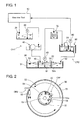
Figure 1 is a system block diagram of a coolant system in an embodiment according to the present invention; -
Figure 2 is a horizontal sectional view of a primary reservoir inFigure 1 ; -
Figure 3 is a plan view of a coolant unit to which the coolant system inFigure 1 is applied; -
Figure 4 is a sectional view taken along the line IV-IV inFigure 3 ; -
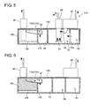
Figure 5 is a sectional view taken along the line V-V inFigure 3 ; -
Figure 6 is a sectional view taken along the line VI-VI inFigure 3 ; and -
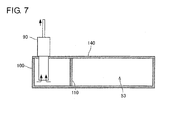
Figure 7 is a sectional view taken along the line VII-VII inFigure 3 . - The system construction of a coolant system in the present embodiment will be described with reference to
Figures 1 and 2 . As shown inFigure 1 , the coolant system is a system for purifying dirty coolant having been used in amachine tool 10. In the coolant system, the dirty coolant is purified by being subjected to filtration at two stages, and the purified coolant is returned to themachine tool 10. - The coolant system is provided with a
collecting reservoir 20, apump 30, aprimary filtering device 40, aprimary reservoir 50, apump 60, asecondary filtering device 70, asecondary reservoir 80, and acirculation pump 90. Thecollecting reservoir 20 collects the coolant discharged form themachine tool 10, that is, the coolant having been used for the machining in themachine tool 10. The coolant contains machining (cutting/grinding) chips, abrasive grains and the like. - A suction port of the
pump 30 is arranged in thecollecting reservoir 20, and a discharge port of thepump 30 is arranged in theprimary filtering device 40. Specifically, by the driving of thepump 30, the dirty coolant stored in thecollecting reservoir 20 is fed to theprimary filtering device 40. A magnet separator is used as theprimary filtering device 40. However, other filtering devices than the magnet separator can be used as theprimary filtering device 40. Theprimary filtering device 40 in the present embodiment mainly removes machining chips of metal contained in the coolant. - The coolant from which the machining chips of metal have been removed by the
primary filtering device 40 is discharged to the primary reservoir 50 (corresponding to the "reservoir" in the claimed invention). That is, theprimary reservoir 50 stores the coolant having the machining chips of metal removed. As shown inFigures 1 and 2 , theprimary reservoir 50 is provided with areservoir frame 51 and apartition member 52. Thereservoir frame 51 forms an outer frame container. Here, thereservoir frame 51 takes a bottomed cylindrical shape. - The
partition member 52 is secured to thereservoir frame 51 so as to partition the interior of thereservoir frame 51 into an outerperipheral coolant tub 53 and acentral coolant tub 54. Thepartition member 52 takes a cylindrical shape. That is, the outerperipheral coolant tub 53 is formed between the inner peripheral surface of thereservoir frame 51 and the outer peripheral surface of thepartition member 52 in the radial direction. In other words, the outerperipheral coolant tub 53 is formed to a doughnut shape. Thecentral coolant tub 54 is formed at a radially inside portion of the internal surface of thepartition member 52. Although formed to have a circular periphery, each of the outerperipheral coolant tub 53 and thecentral coolant tub 54 may take a curved peripheral shape without being limited to the circular periphery. - The
partition member 52 does not take the shape that is partitioned entirely over the whole circumference. Thepartition member 52 is formed with aslit 52a that makes the outerperipheral coolant tub 53 communicate with thecentral coolant tub 54. Theslit 52a is formed to extend in the depth direction. Specifically, the bottom surface of theslit 52a is located on the bottom surface of thereservoir frame 51, and the upper surface of theslit 52a is located above the surface of the coolant stored in theprimary reservoir 50. - Then, a
supply port 45 for supplying coolant from theprimary filtering device 40 to theprimary reservoir 50 is arranged to be oriented toward thecentral coolant tub 54. That is, the coolant filtered by theprimary filtering device 40 is supplied to thecentral coolant tub 54 without passing through the outerperipheral coolant tub 53. In other words, the supply port 45 (corresponding to the "first supply port" in the claimed invention) supplies thecentral coolant tub 54 with the coolant that is fed from themachine tool 10 without passing through the outerperipheral coolant tub 53. Further, thesupply port 45 opens close to the radially outer side in the interior of thecentral coolant tub 54 and is oriented in parallel to the tangential direction to a part close thereto of thepartition member 52. Thus, a rotational flow (counterclockwise inFigure 2 ) is generated in thecentral coolant tub 54 by the coolant supplied from thesupply port 45 to thecentral coolant tub 54. - Further, a
guide member 56 is provided on the internal surface of thepartition member 52 to extend from one end in the circumferential direction of theslit 52a toward the radially inner side. Theguide member 56 is not oriented toward the center and is rather slanted toward theslit 52a side. Thus, theguide member 56 guides the coolant flow in thecentral coolant tub 54 radially inward on the upper stream side than theslit 52a of the rotational flow in thecentral coolant tub 54. - A
suction port 61 of thepump 60 is arranged at the center in thecentral coolant tub 54, and a discharge port of thepump 60 is arranged in thesecondary filtering device 70. That is, by the driving of thepump 60, the coolant stored in thecentral coolant tub 54 is fed to thesecondary filtering device 70. Particularly, thesuction port 61 of thepump 60 is arranged at a position close to the bottom surface at the center of thecentral coolant tub 54. That is, thesuction port 61 of thepump 60 is arranged at the center of the rotational flow of the coolant. - The unit flow rate (flow quantity per unit time) of the coolant supplied from the
supply port 45 to thecentral coolant tub 54 is set to be less than the unit flow rate of the coolant drawn from thesuction port 61 of thepump 60. That is, in the present embodiment, the unit suction flow rate of thepump 30 is set to be less than the unit suction flow rate of thepump 60. - The
secondary filtering device 70 uses a cyclone filtering device and removes machining chips (cutting/grinding chips) and sludge that have not been removed by theprimary filtering device 40. The coolant filtered by thesecondary filtering device 70 becomes coolant having been purified sufficiently. The coolant filtered by thesecondary filtering device 70 is discharged to thesecondary reservoir 80. That is, thesecondary reservoir 80 stores the sufficiently purified coolant. Thesecondary reservoir 80 is provided with athermoregulator 81, and the coolant in thesecondary reservoir 80 is cooled by thethermoregulator 81 to become a constant temperature. - A suction port of the
circulation pump 90 is arranged in thesecondary reservoir 80, and a discharge port of thecirculation pump 90 is connected to a coolant supply device (not shown) on themachine tool 10 side. That is, by the driving of thecirculation pump 90, the coolant stored in thesecondary reservoir 80 is fed to themachine tool 10. - The unit flow rate of the coolant drawn by the
circulation pump 90 is set to be less than the unit flow rate of the coolant drawn by thepump 60. Accordingly, there can arise a state that the stored quantity in thesecondary reservoir 80 exceeds a prescribed quantity. The coolant exceeding the prescribed quantity in thesecondary reservoir 80 is returned from thesecondary reservoir 80 to theprimary reservoir 50. A returningsupply port 82 from thesecondary reservoir 80 to theprimary reservoir 50 is arranged to be oriented toward the outerperipheral coolant tub 53 of theprimary reservoir 50. That is, the coolant that is to overflow from thesecondary reservoir 80 is supplied to the outerperipheral coolant tub 53 without passing through thecentral coolant tub 54. In other words, the returning supply port 82 (corresponding to the "second supply port" in the claimed invention) supplies the outerperipheral coolant tub 53 with at least a part of the coolant that is filtered by thefiltering device 70 and that is led from thefiltering device 70 without passing through thecentral coolant tub 54. - Further, the returning
supply port 82 opens close to the radially outer side in the interior of the outerperipheral coolant tub 53 and is oriented in parallel to the tangential direction to an outer peripheral portion close thereto of thereservoir frame 51. That is, a rotational flow (counterclockwise inFigure 2 ) is generated in the outerperipheral coolant tub 53 by the coolant supplied from the returningsupply port 82 to the outerperipheral coolant tub 53. The rotational flow in the outerperipheral coolant tub 53 and the rotational flow in thecentral coolant tub 54 are made to be the same in rotational direction. - The operation of the aforementioned coolant system will be described with reference to
Figures 1 and 2 . Description will be made separately in two different cases that themachine tool 10 is in operation and that themachine tool 10 is out of operation. - First of all, in the case that the
machine tool 10 is in operation, thecirculation pump 90 and thepumps machine tool 10 is discharged to the collectingreservoir 20 and is fed by the driving of thepump 30 to theprimary filtering device 40. The coolant after filtration by theprimary filtering device 40 is discharged to thecentral coolant tub 54 of theprimary reservoir 50. - The coolant in the
central coolant tub 54 rotates in thecentral coolant tub 54 to move the floating matter in the coolant toward the rotational center side. Thesuction port 61 of thepump 60 is arranged at the rotational center. Thus, the floating matter in the coolant is drawn into thepump 60 together with the coolant rotating in thecentral coolant tub 54. The drawn coolant is fed to thesecondary filtering device 70 and, after being filtered, is discharged to thesecondary reservoir 80. - Particularly, the interior of the
primary reservoir 50 is partitioned by thepartition member 52 into the outerperipheral coolant tub 53 and thecentral coolant tub 54, and the dirty coolant discharged from theprimary filtering device 40 is supplied to thecentral coolant tub 54 that is adjacent to thesuction port 61 of thepump 60. Accordingly, it is possible to reliably feed the dirty coolant to thesecondary filtering device 70 by thepump 60. - Further, the unit flow rate of the coolant supplied from the
primary filtering device 40 to thecentral coolant tub 54 of theprimary reservoir 50 is less than the unit flow rate of the coolant drawn by thepump 60 from thecentral coolant tub 54. Accordingly, the operation is done so that the storage quantity of the coolant in thecentral coolant tub 54 becomes less. That is, the dirty coolant supplied to thecentral coolant tub 54 is further reliably drawn by thepump 60. - The coolant rotating around the internal surface of the
partition member 52 is brought into hit on theguide member 56 before reaching theslit 52a in the rotational direction. Then, the coolant brought into hit on theguide member 56 is guided radially inward, that is, to thesuction port 61 of thepump 60. In this way, since a flow course toward the radial inside is formed just before theslit 52a, it is possible to reliably restrain the coolant in thecentral coolant tub 54 from moving to the outerperipheral coolant tub 53 through theslit 52a. - Then, the coolant stored in the
secondary reservoir 80 after being filtered by thesecondary filtering device 70 is fed by thecirculation pump 90 to themachine tool 10. The unit flow rate of the coolant drawn by thecirculation pump 90 is less than the unit flow rate of the coolant drawn by thepump 60. Thus, there arises a state that the coolant stored in thesecondary reservoir 80 exceeds the prescribed quantity for thesecondary reservoir 80. If this occurs, the coolant is to overflow from thesecondary reservoir 80, and the coolant being to overflow is supplied to the outerperipheral coolant tub 53 of theprimary reservoir 50. - Accordingly, based on the relation between the supply quantity into the
central coolant tub 54, the drawn quantity by thepump 60 and the quantity being to overflow from thesecondary reservoir 80, the flow quantity of the coolant in theprimary reservoir 50 is kept at almost a constant quantity. - Based on this relation of the flow quantities, the coolant in the outer
peripheral coolant tub 53 moves to thecentral coolant tub 54 through theslit 52a. Accordingly, the dirtiest coolant supplied from theprimary filtering device 40 to thecentral coolant tub 54 is reliably drawn by thepump 60 without moving to the outerperipheral coolant tub 53 and is fed to thesecondary filtering device 70. - Further, the coolant in the outer
peripheral coolant tub 53 has been sufficiently purified by thesecondary filtering device 70. However, it may be the case that the coolant also contains floating matter therein. Then, as mentioned above, the coolant in the outerperipheral coolant tub 53 moves to thecentral coolant tub 54, and the floating matter contained in the coolant in the outerperipheral coolant tub 53 also moves to thecentral coolant tub 54. - In addition to this, the coolant in the outer
peripheral coolant tub 53 rotates in the outerperipheral coolant tub 53, and this causes the floating matter in the coolant to move toward the rotational center side. That is, the rotational flow causes the floating matter in the coolant to move toward thepartition member 52 side in the outerperipheral coolant tub 53. The rotational flow in the outerperipheral coolant tub 53 and the rotational flow in thecentral coolant tub 54 are the same in rotational direction. Accordingly, the floating matter being adjacent to theslit 52a in the outerperipheral coolant tub 53 tends to move from the outerperipheral coolant tub 53 to thecentral coolant tub 54 through theslit 52a. - Particularly, the
slit 52a is formed to extend in the depth direction. Thus, the coolant in the outerperipheral coolant tub 53 is led to thecentral coolant tub 54 through a wide area in the depth direction of the outerperipheral coolant tub 53. As a result, the floating matter in the coolant in the outerperipheral coolant tub 53 is led to thecentral coolant tub 54 and is fed by thepump 60 again to thesecondary filtering device 70. That is, the coolant supplied to the outerperipheral coolant tub 53 is filtered again by thesecondary filtering device 70. Consequently, a part of the coolant is purified by being caused to pass through thesecondary filtering device 70 many times. - Next, in the case that the
machine tool 10 is out of operation, thepump 60 only is driven, and thecirculation pump 90 and thepump 30 remain stopped. In this case, coolant is neither supplied from theprimary filtering device 40 to thecentral coolant tub 54 nor fed from thesecondary reservoir 80 to themachine tool 10. - In this case, by the driving of the
pump 60, coolant is fed from thecentral coolant tub 54 to thesecondary filtering device 70 and is discharged from thesecondary filtering device 70 to thesecondary reservoir 80. Since the coolant in thesecondary reservoir 80 is not fed to themachine tool 10, the coolant exceeds the prescribed quantity for thesecondary reservoir 80 and would otherwise overflow from the same. Thus, when exceeding the prescribed quantity, the coolant in thesecondary reservoir 80 is supplied to the outerperipheral coolant tub 53. Then, the coolant moves from the outerperipheral coolant tub 53 to thecentral coolant tub 54. - That is, the coolant circulates in the order of the outer
peripheral coolant tub 53 → thecentral coolant tub 54 → thesecondary filtering device 70 → thesecondary reservoir 80 → the outerperipheral coolant tub 53. During this circulation, the coolant is continuously purified as a result of passing through thesecondary filtering device 70. - In the aforementioned system construction, the collecting
reservoir 20, thepump 30, theprimary filtering device 40, and conduits extending from themachine tool 10 to theprimary filtering device 40 through the collectingreservoir 20 and thepump 30 constitute a first coolant return mechanism CR1 that is arranged to extend from themachine tool 10 to thecentral coolant tub 54 for supplying the coolant discharged from themachine tool 10 to thecentral coolant tub 54 without making the coolant pass through the outerperipheral coolant tub 53. In a modified form, because the coolant after use in themachine tool 10 can be supplied from themachine tool 10 directly to thecentral coolant tub 54, the first coolant return mechanism CR1 may be constituted by at least one conduit having the supply port (first supply port) 45 without including the collectingreservoir 20, thepump 30 and theprimary filtering device 40. In another modified form, because it is possible to discharge the coolant from themachine tool 10 directly to theprimary filtering device 40 which can be placed under a coolant discharge port (not shown) of themachine tool 10, the first coolant return mechanism CR1 may be constituted to merely include theprimary filtering device 40 and the supply port (first supply port) 45. - Further, a conduit leading the coolant from the
secondary reservoir 80 to the outerperipheral coolant tub 53 constitutes a second coolant return mechanism CR2 arranged to extend from thesecondary reservoir 80 to the outerperipheral coolant tub 53 and including the returning supply port (second supply port) 82 for supplying at least a part of the coolant that is to overflow from thesecondary reservoir 80, to the outerperipheral coolant tub 53. - Next, with reference to
Figures 3-7 , description will be made regarding one example of a device that unitizes other components than the collectingreservoir 20 and thepump 30 of the aforementioned coolant system. InFigures 3-7 , the same components as those inFigures 1 and 2 will be given the same reference numerals. - A coolant unit is provided with a unit frame (or reservoir frame) 100, a
partition member 110 partitioning the interior of theunit frame 100 into theprimary reservoir 50 and thesecondary reservoir 80, a flowpassage regulating plate 120 partly partitioning the interior of thesecondary reservoir 80, areturn gutter 130, and acover member 140. Theprimary filtering device 40, thepump 60 and thesecondary filtering device 70 shown inFigure 1 are arranged in the part that constitutes theprimary reservoir 50. Further, thethermoregulator 81 and thecirculation pump 90 are arranged in the part that constitutes thesecondary reservoir 80. - The
return gutter 130 is a flow passage that returns the coolant that would otherwise overflows from thesecondary reservoir 80, to the outerperipheral coolant tub 53 of theprimary reservoir 50. The details of the components that constitute theprimary reservoir 50 are almost the same as those of the construction in the aforementioned coolant system shown inFigures 1 and 2 , and the detailed description therefor will be omitted for the sake of brevity. Thereservoir frame 51 of theprimary reservoir 50 in the foregoing system construction is constituted as theunit frame 100 in the coolant unit, and theunit frame 100 unites into a single body thesecondary reservoir 80 and the primary reservoir 50 (corresponding to the "reservoir" in the claimed invention) whose interior is partitioned into the outerperipheral coolant tub 53 and thecentral coolant tub 54. - Various features and many of the attendant advantages in the foregoing embodiment will be summarized as follows:
- According to the feature of the forgoing embodiment in the first aspect described in the summary of the invention and shown in
Figures 1 and 2 , the following advantages can be achieved. That is, the interior of thereservoir 50 is partitioned by thepartition member 52 into the outerperipheral coolant tub 53 and thecentral coolant tub 54. Thesuction port 61 of thesecond pump 60 that feeds the coolant from thereservoir 50 to thefiltering device 70 is arranged in thecentral coolant tub 54 in the interior of thereservoir 50. Then, the coolant discharged from themachine tool 10 is supplied to thecentral coolant tub 54 without passing through the outerperipheral coolant tub 53. That is, the dirty coolant discharged from themachine tool 10 is supplied to thecentral coolant tub 54 arranging thesuction port 61 of thesecond pump 60 therein. Accordingly, it is possible to reliably feed the dirty coolant to thefiltering device 70 by thesecond pump 60. Further, the coolant having been filtered by thefiltering device 70 is supplied to the outerperipheral coolant tub 53. Since thepartition member 52 is formed with theslit 52a, it is possible to move the coolant supplied to the outerperipheral coolant tub 53 from the same to thecentral coolant tub 54 through theslit 52a. In addition, theslit 52a is formed to extend in the depth direction. Therefore, the coolant in the outerperipheral coolant tub 53 is led to thecentral coolant tub 54 through a wide area in the depth direction of the outerperipheral coolant tub 53. As a result, as the coolant containing the floating matter in the outerperipheral coolant tub 53 is led to thecentral coolant tub 54 and is fed by thesecond pump 60 from thecentral coolant tub 54 to thefiltering device 70, whereby the floating matter is removed. - According to the feature of the forgoing embodiment in a second aspect shown in
Figures 1 and 2 , the supply port (first supply port) 45 is oriented to generate the rotational flow of the coolant in thecentral coolant tub 54. Thesuction port 61 of thesecond pump 60 is arranged at the center of thecentral coolant tub 54. Thus, it is possible to move the floating matter in thecentral coolant tub 54 to the rotational center by generating the rotational flow in thecentral coolant tub 54. Since thesuction port 61 of thesecond pump 60 is arranged at the center of the rotational flow, it is possible to reliably draw the floating matter in the coolant in thecentral coolant tub 54 by thesecond pump 60 and to feed the floating matter to thefiltering device 70. - According to the feature of the forgoing embodiment in a third aspect shown in
Figures 1 and 2 , theguide member 56 is provided on the internal surface of thepartition member 52 on the upper stream side than theslit 52a in the rotational flow of the coolant in thecentral coolant tub 54 for guiding the flow of coolant in thecentral coolant tub 54 radially inward of thecentral coolant tub 54. Thus, although an anxiety may otherwise arise that theslit 52a of thepartition member 52 causes the coolant to move from thecentral coolant tub 54 to the outerperipheral coolant tub 53, it is possible by providing theguide member 56 to restrain the coolant in thecentral coolant tub 54 from moving to the outerperipheral coolant tub 53 through theslit 52a. Particularly, the arrangement of theguide member 56 is made taking the rotational direction of the coolant in thecentral coolant tub 54 into consideration. Specifically, since theguide member 56 is provided on the upper stream side than theslit 56, the coolant rotating around the internal surface of thepartition member 52 is brought into hit on theguide member 56. The coolant brought into hit on theguide member 56 is guided radially inward, that is, to thesuction port 61 of thesecond pump 60. In this way, since the flow direction toward the radially inner side is formed just before theslit 52a, it is possible to reliably restrain the coolant in thecentral coolant tub 54 from moving to the outerperipheral coolant tub 53 through theslit 52a. - According to the feature of the forgoing embodiment in a fourth aspect shown in
Figures 1 and 2 , the supply port (second supply port) 82 is oriented to generate the rotational flow of the coolant in the outerperipheral coolant tub 53, and the rotational flow in thecentral coolant tub 54 and the rotational flow in the outerperipheral coolant tub 53 are the same in rotational direction. Thus, by generating the rotational flow in the outerperipheral coolant tub 53, it is possible to move the floating matter in the coolant in the outerperipheral coolant tub 53 toward the rotational center side, that is, toward thecentral coolant tub 54 side. Furthermore, since the rotational flow in thecentral coolant tub 54 and the rotational flow in the outerperipheral coolant tub 53 are made to be the same in rotational direction. Therefore, the floating matter being adjacent to theslit 52a tends to move from the outerperipheral coolant tub 53 side toward thecentral coolant tub 54 side. Accordingly, it is possible to reliably move the floating matter in the coolant in the outerperipheral coolant tub 53 to the rotational center of thecentral coolant tub 54, and hence to feed the floating matter to thefiltering device 70 by thesecond pump 60. - According to the feature of the forgoing embodiment in a fifth aspect shown in
Figures 1 and 2 , the flow quantity per unit time of the coolant that is supplied from themachine tool 10 to thecentral coolant tub 54 without passing through the outerperipheral coolant tub 53 is set to be less than the flow quantity per unit time of the coolant that is drawn from thesuction port 61 of thesecond pump 60. Thus, the operation is performed so that the coolant in thecentral coolant tub 54 decreases in storage quantity. That is, the dirtiest coolant discharged from themachine tool 10 can reliably be drawn by thesecond pump 60. The outerperipheral coolant tub 53 and thecentral coolant tub 54 are in communication through theslit 52a. Therefore, by making the unit flow rate of the coolant drawn by thesecond pump 60 more than the unit flow rate of the coolant supplied to thecentral coolant tub 54, it results that the coolant in the outerperipheral coolant tub 53 moves to thecentral coolant tub 54 through theslit 52a. Accordingly, it is possible to make the coolant in thecentral coolant tub 54 and the coolant in the outerperipheral coolant tub 53 drawn reliably by thesecond pump 60. - According to the feature of the forgoing embodiment in a sixth aspect shown in
Figures 1 and 2 , the first coolant return mechanism CR1 is arranged to extend from themachine tool 10 to thecentral coolant tub 54 for supplying the coolant discharged from themachine tool 10 to thecentral coolant tub 53, and the first coolant return mechanism CR1 includes the supply port (first supply port) 45 and theprimary filtering device 40 that removes machining chips of metal contained in the coolant discharged from themachine tool 10 and that supplies to thecentral coolant tub 54 the coolant from which the machining chips of metal have been removed. Therefore, thecentral coolant tub 54 can be supplied with the coolant from which the machining chips of metal have been removed to some degree. - According to the feature of the forgoing embodiment in a seventh aspect shown in
Figures 1 and 2 , thesecondary reservoir 80 is supplied with the coolant filtered by thefiltering device 70, and the second coolant return mechanism CR2 is arranged to extend from thesecondary reservoir 80 to the outerperipheral coolant tub 53. The second coolant return mechanism CR2 includes the supply port (second supply port) 82 for supplying at least the part of the coolant that is to overflow from thesecondary reservoir 80, to the outerperipheral coolant tub 53. Therefore, the outerperipheral coolant tub 53 is supplied with the coolant that has been filtered by thefiltering device 70 and that is to overflow from thesecondary reservoir 80. - According to the feature of the forgoing embodiment in an eighth aspect typically shown in
Figure 3 , thereservoir frame 51 is constituted as theunit frame 100 that unites into a single body thesecondary reservoir 80 and thereservoir 50 whose interior is partitioned into the outerperipheral coolant tub 53 and thecentral coolant tub 54. Therefore, thesecondary reservoir 80 and thereservoir 50 can be united into a single body so as to become easier and expedient in manufacturing, handling and transporting. - Obviously, numerous modifications and variations of the present invention are possible in light of the above teachings. It is therefore to be understood that within the scope of the appended claims, the present invention may be practiced otherwise than as specifically described herein.
- In a coolant system, the interior of a reservoir frame (51) storing the coolant discharged from a machine tool (10) is partitioned by a partition member (52) into an outer peripheral coolant tub (53) and a central coolant tub (54). The partition member (52) is formed with a silt (52a) that extends in the depth direction to make the outer peripheral coolant tub (53) communicate with the central coolant tub (54). A suction port (61) of a pump (60) that feeds the coolant in the central coolant tub (54) to a filtering device (70) is arranged in the central coolant tub (54). The coolant discharged from the machine tool (10) is supplied to the central coolant tub (54) without passing through the outer peripheral coolant tub (53). At least a part of the coolant filtered by the filtering device (70) is supplied to the outer peripheral coolant tub (53) without passing through the central coolant tub (54).
Claims (8)
- A coolant system comprising:a reservoir (50) that stores coolant discharged from a machine tool (10);a filtering device (70) that filters the coolant in the reservoir (50);a first pump (90) that feeds the coolant after filtration to the machine tool (10); anda second pump (60) that feeds the coolant in the reservoir (50) to the filtering device (70);wherein the reservoir (50) comprises:a reservoir frame (51); anda partition member (52) that partitions the interior of the reservoir frame (51) into an outer peripheral coolant tub (53) and a central coolant tub (54) and that is formed with a slit (52a) extending in the depth direction to make the outer peripheral coolant tub (53) communicate with the central coolant tub (54);wherein a suction port (61) of the second pump (60) is arranged in the central coolant tub (54);the system further comprising:a first supply port (45) that supplies the central coolant tub (54) with the coolant fed from the machine tool (10) without passing through the outer peripheral coolant tub (53); anda second supply port (82) that supplies the outer peripheral coolant tub (53) with at least a part of the coolant filtered by the filtering device (70) and fed from the filtering device (70) without passing through the central coolant tub (54).
- The coolant system in Claim 1, wherein:the first supply port (45) is oriented to generate a rotational flow of the coolant in the central coolant tub (54); andthe suction port (61) of the second pump (60) is arranged at the center of the central coolant tub (54).
- The coolant system in Claim 2, further comprising:a guide member (56) that is provided on an internal surface of the partition member (52) on an upper stream side than the slit (52a) in the rotational flow of the coolant in the central coolant tub (54) for guiding the flow of the coolant in the central coolant tub (54) radially inward of the central coolant tub (54).
- The coolant system in Claim 2 or 3, wherein:the second supply port (82) is oriented to generate a rotational flow of the coolant in the outer peripheral coolant tub (53); andthe rotational flow in the central coolant tub (54) and the rotational flow in the outer peripheral coolant tub (53) are the same in rotational direction.
- The coolant system in any one of Claims 1 to 4, wherein:the flow quantity per unit time of the coolant that is supplied from the machine tool (10) to the central coolant tub (54) without passing through the outer peripheral coolant tub (53) is set to be less than the flow quantity per unit time of the coolant that is drawn from the suction port (61) of the second pump (60).
- The coolant system in any one of Claims 1 to 5, further comprising:a first coolant return mechanism (CR1) arranged to extend from the machine tool (10) to the central coolant tub (54) for supplying the coolant discharged from the machine tool (10) to the central coolant tub (54); the first coolant return mechanism (CR1) including:the first supply port (45); anda primary filtering device (40) that removes machining chips of metal contained in the coolant discharged from the machine tool (10) and that supplies to the central coolant tub (54) the coolant from which the machining chips of metal have been removed.
- The coolant system in any one of Claims 1 to 6, further comprising:a secondary reservoir (80) that is supplied with the coolant filtered by the filtering device (70); anda second coolant return mechanism (CR2) arranged to extend from the secondary reservoir (80) to the outer peripheral coolant tub (53) and including the second supply port (82) for supplying at least the part of the coolant that is to overflow from the secondary reservoir (80), to the outer peripheral coolant tub (53).
- The coolant system in Claim 7, wherein:the reservoir frame (51) is constituted as a unit frame (100) that unites into a single body the secondary reservoir (80) and the reservoir (50) whose interior is partitioned into the outer peripheral coolant tub (53) and the central coolant tub (54).
Applications Claiming Priority (1)
| Application Number | Priority Date | Filing Date | Title |
|---|---|---|---|
| JP2012238510A JP5930938B2 (en) | 2012-10-30 | 2012-10-30 | Coolant system |
Publications (2)
| Publication Number | Publication Date |
|---|---|
| EP2727683A1 true EP2727683A1 (en) | 2014-05-07 |
| EP2727683B1 EP2727683B1 (en) | 2015-07-22 |
Family
ID=49485584
Family Applications (1)
| Application Number | Title | Priority Date | Filing Date |
|---|---|---|---|
| EP13190190.2A Active EP2727683B1 (en) | 2012-10-30 | 2013-10-25 | Coolant system |
Country Status (4)
| Country | Link |
|---|---|
| US (1) | US9393571B2 (en) |
| EP (1) | EP2727683B1 (en) |
| JP (1) | JP5930938B2 (en) |
| CN (1) | CN103786064B (en) |
Families Citing this family (18)
| Publication number | Priority date | Publication date | Assignee | Title |
|---|---|---|---|---|
| US20150197429A1 (en) * | 2009-11-20 | 2015-07-16 | George Schade | Holding tank for garnet extraction system |
| JP5930938B2 (en) * | 2012-10-30 | 2016-06-08 | 株式会社ジェイテクト | Coolant system |
| CA2944020C (en) * | 2014-03-27 | 2021-04-06 | Asama Coldwater Manufacturing Inc. | Filtration system |
| JP6481379B2 (en) * | 2015-01-19 | 2019-03-13 | いすゞ自動車株式会社 | Coolant waste recovery device |
| CN106425873A (en) * | 2016-10-13 | 2017-02-22 | 新野鼎泰电子精工科技有限公司 | Centralized filtration and oil supply system for machine tool machining |
| JP7021553B2 (en) * | 2018-02-13 | 2022-02-17 | トヨタ自動車株式会社 | Coolant tank |
| US12179299B2 (en) * | 2018-08-07 | 2024-12-31 | Illinois Tool Works Inc. | Machine tool with recirculating coolant filtration system |
| US20200078894A1 (en) * | 2018-09-07 | 2020-03-12 | Manufacturing Productivity Systems | Coolant filtration system |
| CN109318046A (en) * | 2018-12-04 | 2019-02-12 | 苏州帝瀚环保科技股份有限公司 | A kind of machine tool cutting liquid recovery system |
| JP7221113B2 (en) * | 2019-03-29 | 2023-02-13 | 住友重機械ファインテック株式会社 | Liquid circulators and tanks for machine tools |
| JP6738942B1 (en) * | 2019-06-24 | 2020-08-12 | Dmg森精機株式会社 | Sludge treatment equipment and sludge treatment system Machine tools |
| WO2022056723A1 (en) * | 2020-09-16 | 2022-03-24 | Illinois Tool Works Inc. | Standpipe recirculation systems for material removal machines |
| JP6984925B1 (en) * | 2021-02-25 | 2021-12-22 | 株式会社ブンリ | Filtration device |
| US20250146770A1 (en) * | 2021-08-20 | 2025-05-08 | Dmg Mori Co., Ltd. | Coolant processing device |
| CN115213734A (en) * | 2022-09-20 | 2022-10-21 | 江苏威泽智能科技股份有限公司 | Quick filter equipment of cutting fluid for digit control machine tool |
| JP2024066887A (en) * | 2022-11-02 | 2024-05-16 | オークマ株式会社 | Cutting fluid circulation device |
| JP2024136414A (en) * | 2023-03-24 | 2024-10-04 | 光精工株式会社 | Coolant tank |
| JP2024147396A (en) * | 2023-04-03 | 2024-10-16 | オークマ株式会社 | Cutting fluid circulation device |
Citations (5)
| Publication number | Priority date | Publication date | Assignee | Title |
|---|---|---|---|---|
| JP2003175437A (en) | 2001-12-13 | 2003-06-24 | Ogusu Kinzoku Kogyosho:Kk | Eddy current circulation type coolant purifying apparatus |
| JP2006055981A (en) | 2004-08-17 | 2006-03-02 | Cnk:Kk | Coolant cleaning device |
| WO2008035551A1 (en) | 2006-09-21 | 2008-03-27 | Sumitomo Heavy Industries Finetech, Ltd. | Coolant cleaning device for machine tool |
| JP2012045678A (en) | 2010-08-27 | 2012-03-08 | Nikuni:Kk | Liquid treating device |
| JP2012125909A (en) | 2010-12-15 | 2012-07-05 | Yoshitsugu Inoue | Processing device of coolant liquid |
Family Cites Families (5)
| Publication number | Priority date | Publication date | Assignee | Title |
|---|---|---|---|---|
| JP2954800B2 (en) * | 1993-01-13 | 1999-09-27 | 榎本工業株式会社 | Solid body recovery device |
| JP3813239B2 (en) * | 1996-05-24 | 2006-08-23 | ヤマハ発動機株式会社 | Machine dust removal device for coolant for machine tools |
| JP2005319566A (en) * | 2004-05-06 | 2005-11-17 | Cnk:Kk | Coolant cleaning device |
| JP2006043820A (en) * | 2004-08-05 | 2006-02-16 | Ogusu Kinzoku Kogyosho:Kk | Eddy current circulation type coolant purifying apparatus |
| JP5930938B2 (en) * | 2012-10-30 | 2016-06-08 | 株式会社ジェイテクト | Coolant system |
-
2012
- 2012-10-30 JP JP2012238510A patent/JP5930938B2/en active Active
-
2013
- 2013-10-18 CN CN201310491957.6A patent/CN103786064B/en active Active
- 2013-10-25 EP EP13190190.2A patent/EP2727683B1/en active Active
- 2013-10-29 US US14/065,887 patent/US9393571B2/en active Active
Patent Citations (6)
| Publication number | Priority date | Publication date | Assignee | Title |
|---|---|---|---|---|
| JP2003175437A (en) | 2001-12-13 | 2003-06-24 | Ogusu Kinzoku Kogyosho:Kk | Eddy current circulation type coolant purifying apparatus |
| JP2006055981A (en) | 2004-08-17 | 2006-03-02 | Cnk:Kk | Coolant cleaning device |
| WO2008035551A1 (en) | 2006-09-21 | 2008-03-27 | Sumitomo Heavy Industries Finetech, Ltd. | Coolant cleaning device for machine tool |
| EP2065127A1 (en) * | 2006-09-21 | 2009-06-03 | Sumitomo Heavy Industries Finetech, Ltd. | Coolant cleaning device for machine tool |
| JP2012045678A (en) | 2010-08-27 | 2012-03-08 | Nikuni:Kk | Liquid treating device |
| JP2012125909A (en) | 2010-12-15 | 2012-07-05 | Yoshitsugu Inoue | Processing device of coolant liquid |
Also Published As
| Publication number | Publication date |
|---|---|
| US20140116930A1 (en) | 2014-05-01 |
| CN103786064B (en) | 2017-07-14 |
| EP2727683B1 (en) | 2015-07-22 |
| CN103786064A (en) | 2014-05-14 |
| JP2014087871A (en) | 2014-05-15 |
| JP5930938B2 (en) | 2016-06-08 |
| US9393571B2 (en) | 2016-07-19 |
Similar Documents
| Publication | Publication Date | Title |
|---|---|---|
| EP2727683B1 (en) | Coolant system | |
| US9457445B2 (en) | Machine tool with cover adapted for discharge of chips | |
| US10561970B2 (en) | Filtration device | |
| US20250178144A1 (en) | Coolant Supply Device | |
| KR102062698B1 (en) | Metal cutting processing apparatus for using shifting pump capable of pressure conveying cutting oil | |
| CN111069970A (en) | Cutting fluid tank for machine tool | |
| CN104147812B (en) | Oily-water seperating equipment | |
| KR102886308B1 (en) | Coolant tank device of machine tool | |
| KR102384397B1 (en) | Cutting oil recorvery apparatus for tool machine | |
| KR20130019126A (en) | Screw type cutting oil purification apparatus | |
| EP4119289B1 (en) | Machine tool with a chip processing device | |
| EP3431224B1 (en) | Coolant supply device | |
| JP2015044266A (en) | Coolant tank device | |
| KR101806409B1 (en) | Oil Separator | |
| KR20180037471A (en) | The cutting oil filter for the chip discharge apparatus | |
| EP4461413A1 (en) | Defoaming structure of separation device | |
| JP6061719B2 (en) | Coolant system | |
| KR101841403B1 (en) | Lapping device for cylinder block having circulation Pump | |
| KR20150051439A (en) | Cutting oil refining apparatus for machine tool | |
| KR101504135B1 (en) | Apparatus For Filtering Impurities Out Of Oil | |
| JP2018065238A (en) | Work collection device and machine tool provided with the same | |
| US8871101B2 (en) | Liquid separator including venturi device | |
| KR101001251B1 (en) | Coolant's Purifier | |
| KR20200002350U (en) | Metalworking fluid refine device | |
| KR20090130966A (en) | Filtration Unit for Process Oil Feeder |
Legal Events
| Date | Code | Title | Description |
|---|---|---|---|
| PUAI | Public reference made under article 153(3) epc to a published international application that has entered the european phase |
Free format text: ORIGINAL CODE: 0009012 |
|
| 17P | Request for examination filed |
Effective date: 20131025 |
|
| AK | Designated contracting states |
Kind code of ref document: A1 Designated state(s): AL AT BE BG CH CY CZ DE DK EE ES FI FR GB GR HR HU IE IS IT LI LT LU LV MC MK MT NL NO PL PT RO RS SE SI SK SM TR |
|
| AX | Request for extension of the european patent |
Extension state: BA ME |
|
| 17P | Request for examination filed |
Effective date: 20140616 |
|
| 17Q | First examination report despatched |
Effective date: 20140714 |
|
| GRAP | Despatch of communication of intention to grant a patent |
Free format text: ORIGINAL CODE: EPIDOSNIGR1 |
|
| INTG | Intention to grant announced |
Effective date: 20150202 |
|
| GRAS | Grant fee paid |
Free format text: ORIGINAL CODE: EPIDOSNIGR3 |
|
| GRAA | (expected) grant |
Free format text: ORIGINAL CODE: 0009210 |
|
| AK | Designated contracting states |
Kind code of ref document: B1 Designated state(s): AL AT BE BG CH CY CZ DE DK EE ES FI FR GB GR HR HU IE IS IT LI LT LU LV MC MK MT NL NO PL PT RO RS SE SI SK SM TR |
|
| REG | Reference to a national code |
Ref country code: GB Ref legal event code: FG4D |
|
| REG | Reference to a national code |
Ref country code: CH Ref legal event code: EP |
|
| REG | Reference to a national code |
Ref country code: IE Ref legal event code: FG4D |
|
| REG | Reference to a national code |
Ref country code: AT Ref legal event code: REF Ref document number: 737609 Country of ref document: AT Kind code of ref document: T Effective date: 20150815 |
|
| REG | Reference to a national code |
Ref country code: DE Ref legal event code: R096 Ref document number: 602013002368 Country of ref document: DE |
|
| REG | Reference to a national code |
Ref country code: AT Ref legal event code: MK05 Ref document number: 737609 Country of ref document: AT Kind code of ref document: T Effective date: 20150722 |
|
| REG | Reference to a national code |
Ref country code: LT Ref legal event code: MG4D |
|
| REG | Reference to a national code |
Ref country code: NL Ref legal event code: MP Effective date: 20150722 |
|
| PG25 | Lapsed in a contracting state [announced via postgrant information from national office to epo] |
Ref country code: NO Free format text: LAPSE BECAUSE OF FAILURE TO SUBMIT A TRANSLATION OF THE DESCRIPTION OR TO PAY THE FEE WITHIN THE PRESCRIBED TIME-LIMIT Effective date: 20151022 Ref country code: GR Free format text: LAPSE BECAUSE OF FAILURE TO SUBMIT A TRANSLATION OF THE DESCRIPTION OR TO PAY THE FEE WITHIN THE PRESCRIBED TIME-LIMIT Effective date: 20151023 Ref country code: LV Free format text: LAPSE BECAUSE OF FAILURE TO SUBMIT A TRANSLATION OF THE DESCRIPTION OR TO PAY THE FEE WITHIN THE PRESCRIBED TIME-LIMIT Effective date: 20150722 Ref country code: LT Free format text: LAPSE BECAUSE OF FAILURE TO SUBMIT A TRANSLATION OF THE DESCRIPTION OR TO PAY THE FEE WITHIN THE PRESCRIBED TIME-LIMIT Effective date: 20150722 Ref country code: FI Free format text: LAPSE BECAUSE OF FAILURE TO SUBMIT A TRANSLATION OF THE DESCRIPTION OR TO PAY THE FEE WITHIN THE PRESCRIBED TIME-LIMIT Effective date: 20150722 |
|
| PG25 | Lapsed in a contracting state [announced via postgrant information from national office to epo] |
Ref country code: AT Free format text: LAPSE BECAUSE OF FAILURE TO SUBMIT A TRANSLATION OF THE DESCRIPTION OR TO PAY THE FEE WITHIN THE PRESCRIBED TIME-LIMIT Effective date: 20150722 Ref country code: PL Free format text: LAPSE BECAUSE OF FAILURE TO SUBMIT A TRANSLATION OF THE DESCRIPTION OR TO PAY THE FEE WITHIN THE PRESCRIBED TIME-LIMIT Effective date: 20150722 Ref country code: PT Free format text: LAPSE BECAUSE OF FAILURE TO SUBMIT A TRANSLATION OF THE DESCRIPTION OR TO PAY THE FEE WITHIN THE PRESCRIBED TIME-LIMIT Effective date: 20151123 Ref country code: ES Free format text: LAPSE BECAUSE OF FAILURE TO SUBMIT A TRANSLATION OF THE DESCRIPTION OR TO PAY THE FEE WITHIN THE PRESCRIBED TIME-LIMIT Effective date: 20150722 Ref country code: RS Free format text: LAPSE BECAUSE OF FAILURE TO SUBMIT A TRANSLATION OF THE DESCRIPTION OR TO PAY THE FEE WITHIN THE PRESCRIBED TIME-LIMIT Effective date: 20150722 Ref country code: IS Free format text: LAPSE BECAUSE OF FAILURE TO SUBMIT A TRANSLATION OF THE DESCRIPTION OR TO PAY THE FEE WITHIN THE PRESCRIBED TIME-LIMIT Effective date: 20151122 Ref country code: HR Free format text: LAPSE BECAUSE OF FAILURE TO SUBMIT A TRANSLATION OF THE DESCRIPTION OR TO PAY THE FEE WITHIN THE PRESCRIBED TIME-LIMIT Effective date: 20150722 Ref country code: SE Free format text: LAPSE BECAUSE OF FAILURE TO SUBMIT A TRANSLATION OF THE DESCRIPTION OR TO PAY THE FEE WITHIN THE PRESCRIBED TIME-LIMIT Effective date: 20150722 |
|
| REG | Reference to a national code |
Ref country code: DE Ref legal event code: R097 Ref document number: 602013002368 Country of ref document: DE |
|
| PG25 | Lapsed in a contracting state [announced via postgrant information from national office to epo] |
Ref country code: EE Free format text: LAPSE BECAUSE OF FAILURE TO SUBMIT A TRANSLATION OF THE DESCRIPTION OR TO PAY THE FEE WITHIN THE PRESCRIBED TIME-LIMIT Effective date: 20150722 Ref country code: CZ Free format text: LAPSE BECAUSE OF FAILURE TO SUBMIT A TRANSLATION OF THE DESCRIPTION OR TO PAY THE FEE WITHIN THE PRESCRIBED TIME-LIMIT Effective date: 20150722 Ref country code: DK Free format text: LAPSE BECAUSE OF FAILURE TO SUBMIT A TRANSLATION OF THE DESCRIPTION OR TO PAY THE FEE WITHIN THE PRESCRIBED TIME-LIMIT Effective date: 20150722 Ref country code: IT Free format text: LAPSE BECAUSE OF FAILURE TO SUBMIT A TRANSLATION OF THE DESCRIPTION OR TO PAY THE FEE WITHIN THE PRESCRIBED TIME-LIMIT Effective date: 20150722 Ref country code: SK Free format text: LAPSE BECAUSE OF FAILURE TO SUBMIT A TRANSLATION OF THE DESCRIPTION OR TO PAY THE FEE WITHIN THE PRESCRIBED TIME-LIMIT Effective date: 20150722 |
|
| PLBE | No opposition filed within time limit |
Free format text: ORIGINAL CODE: 0009261 |
|
| STAA | Information on the status of an ep patent application or granted ep patent |
Free format text: STATUS: NO OPPOSITION FILED WITHIN TIME LIMIT |
|
| PG25 | Lapsed in a contracting state [announced via postgrant information from national office to epo] |
Ref country code: RO Free format text: LAPSE BECAUSE OF FAILURE TO SUBMIT A TRANSLATION OF THE DESCRIPTION OR TO PAY THE FEE WITHIN THE PRESCRIBED TIME-LIMIT Effective date: 20150722 Ref country code: LU Free format text: LAPSE BECAUSE OF FAILURE TO SUBMIT A TRANSLATION OF THE DESCRIPTION OR TO PAY THE FEE WITHIN THE PRESCRIBED TIME-LIMIT Effective date: 20151025 |
|
| 26N | No opposition filed |
Effective date: 20160425 |
|
| PG25 | Lapsed in a contracting state [announced via postgrant information from national office to epo] |
Ref country code: MC Free format text: LAPSE BECAUSE OF FAILURE TO SUBMIT A TRANSLATION OF THE DESCRIPTION OR TO PAY THE FEE WITHIN THE PRESCRIBED TIME-LIMIT Effective date: 20150722 |
|
| REG | Reference to a national code |
Ref country code: IE Ref legal event code: MM4A |
|
| REG | Reference to a national code |
Ref country code: FR Ref legal event code: ST Effective date: 20160630 |
|
| PG25 | Lapsed in a contracting state [announced via postgrant information from national office to epo] |
Ref country code: SI Free format text: LAPSE BECAUSE OF FAILURE TO SUBMIT A TRANSLATION OF THE DESCRIPTION OR TO PAY THE FEE WITHIN THE PRESCRIBED TIME-LIMIT Effective date: 20150722 Ref country code: FR Free format text: LAPSE BECAUSE OF NON-PAYMENT OF DUE FEES Effective date: 20151102 |
|
| PG25 | Lapsed in a contracting state [announced via postgrant information from national office to epo] |
Ref country code: IE Free format text: LAPSE BECAUSE OF NON-PAYMENT OF DUE FEES Effective date: 20151025 |
|
| PG25 | Lapsed in a contracting state [announced via postgrant information from national office to epo] |
Ref country code: BE Free format text: LAPSE BECAUSE OF FAILURE TO SUBMIT A TRANSLATION OF THE DESCRIPTION OR TO PAY THE FEE WITHIN THE PRESCRIBED TIME-LIMIT Effective date: 20150722 |
|
| PG25 | Lapsed in a contracting state [announced via postgrant information from national office to epo] |
Ref country code: BG Free format text: LAPSE BECAUSE OF FAILURE TO SUBMIT A TRANSLATION OF THE DESCRIPTION OR TO PAY THE FEE WITHIN THE PRESCRIBED TIME-LIMIT Effective date: 20150722 Ref country code: HU Free format text: LAPSE BECAUSE OF FAILURE TO SUBMIT A TRANSLATION OF THE DESCRIPTION OR TO PAY THE FEE WITHIN THE PRESCRIBED TIME-LIMIT; INVALID AB INITIO Effective date: 20131025 |
|
| REG | Reference to a national code |
Ref country code: CH Ref legal event code: PL |
|
| PG25 | Lapsed in a contracting state [announced via postgrant information from national office to epo] |
Ref country code: NL Free format text: LAPSE BECAUSE OF FAILURE TO SUBMIT A TRANSLATION OF THE DESCRIPTION OR TO PAY THE FEE WITHIN THE PRESCRIBED TIME-LIMIT Effective date: 20150722 Ref country code: CY Free format text: LAPSE BECAUSE OF FAILURE TO SUBMIT A TRANSLATION OF THE DESCRIPTION OR TO PAY THE FEE WITHIN THE PRESCRIBED TIME-LIMIT Effective date: 20150722 |
|
| PG25 | Lapsed in a contracting state [announced via postgrant information from national office to epo] |
Ref country code: CH Free format text: LAPSE BECAUSE OF NON-PAYMENT OF DUE FEES Effective date: 20161031 Ref country code: LI Free format text: LAPSE BECAUSE OF NON-PAYMENT OF DUE FEES Effective date: 20161031 |
|
| PG25 | Lapsed in a contracting state [announced via postgrant information from national office to epo] |
Ref country code: MT Free format text: LAPSE BECAUSE OF FAILURE TO SUBMIT A TRANSLATION OF THE DESCRIPTION OR TO PAY THE FEE WITHIN THE PRESCRIBED TIME-LIMIT Effective date: 20150722 |
|
| PG25 | Lapsed in a contracting state [announced via postgrant information from national office to epo] |
Ref country code: SM Free format text: LAPSE BECAUSE OF FAILURE TO SUBMIT A TRANSLATION OF THE DESCRIPTION OR TO PAY THE FEE WITHIN THE PRESCRIBED TIME-LIMIT Effective date: 20150722 |
|
| GBPC | Gb: european patent ceased through non-payment of renewal fee |
Effective date: 20171025 |
|
| PG25 | Lapsed in a contracting state [announced via postgrant information from national office to epo] |
Ref country code: MK Free format text: LAPSE BECAUSE OF FAILURE TO SUBMIT A TRANSLATION OF THE DESCRIPTION OR TO PAY THE FEE WITHIN THE PRESCRIBED TIME-LIMIT Effective date: 20150722 |
|
| PG25 | Lapsed in a contracting state [announced via postgrant information from national office to epo] |
Ref country code: GB Free format text: LAPSE BECAUSE OF NON-PAYMENT OF DUE FEES Effective date: 20171025 |
|
| PG25 | Lapsed in a contracting state [announced via postgrant information from national office to epo] |
Ref country code: TR Free format text: LAPSE BECAUSE OF FAILURE TO SUBMIT A TRANSLATION OF THE DESCRIPTION OR TO PAY THE FEE WITHIN THE PRESCRIBED TIME-LIMIT Effective date: 20150722 Ref country code: AL Free format text: LAPSE BECAUSE OF FAILURE TO SUBMIT A TRANSLATION OF THE DESCRIPTION OR TO PAY THE FEE WITHIN THE PRESCRIBED TIME-LIMIT Effective date: 20150722 |
|
| PGFP | Annual fee paid to national office [announced via postgrant information from national office to epo] |
Ref country code: DE Payment date: 20250902 Year of fee payment: 13 |