EP3395498B1 - Filtration device - Google Patents
Filtration device Download PDFInfo
- Publication number
- EP3395498B1 EP3395498B1 EP16878117.7A EP16878117A EP3395498B1 EP 3395498 B1 EP3395498 B1 EP 3395498B1 EP 16878117 A EP16878117 A EP 16878117A EP 3395498 B1 EP3395498 B1 EP 3395498B1
- Authority
- EP
- European Patent Office
- Prior art keywords
- tank
- conveyer
- primary
- clean
- liquid
- Prior art date
- Legal status (The legal status is an assumption and is not a legal conclusion. Google has not performed a legal analysis and makes no representation as to the accuracy of the status listed.)
- Active
Links
- 238000001914 filtration Methods 0.000 title claims description 58
- 239000007788 liquid Substances 0.000 claims description 110
- 239000010802 sludge Substances 0.000 claims description 46
- 238000007790 scraping Methods 0.000 claims description 20
- 238000004891 communication Methods 0.000 claims description 6
- 238000005192 partition Methods 0.000 claims description 5
- 239000002826 coolant Substances 0.000 description 12
- 239000010419 fine particle Substances 0.000 description 3
- 238000012423 maintenance Methods 0.000 description 2
- 238000007493 shaping process Methods 0.000 description 2
- 229910001220 stainless steel Inorganic materials 0.000 description 2
- 239000010935 stainless steel Substances 0.000 description 2
- 239000000126 substance Substances 0.000 description 2
- 238000004140 cleaning Methods 0.000 description 1
- 239000002440 industrial waste Substances 0.000 description 1
- 239000002184 metal Substances 0.000 description 1
- 239000002245 particle Substances 0.000 description 1
- 238000001259 photo etching Methods 0.000 description 1
- 238000004080 punching Methods 0.000 description 1
Images


Classifications
-
- B—PERFORMING OPERATIONS; TRANSPORTING
- B23—MACHINE TOOLS; METAL-WORKING NOT OTHERWISE PROVIDED FOR
- B23Q—DETAILS, COMPONENTS, OR ACCESSORIES FOR MACHINE TOOLS, e.g. ARRANGEMENTS FOR COPYING OR CONTROLLING; MACHINE TOOLS IN GENERAL CHARACTERISED BY THE CONSTRUCTION OF PARTICULAR DETAILS OR COMPONENTS; COMBINATIONS OR ASSOCIATIONS OF METAL-WORKING MACHINES, NOT DIRECTED TO A PARTICULAR RESULT
- B23Q11/00—Accessories fitted to machine tools for keeping tools or parts of the machine in good working condition or for cooling work; Safety devices specially combined with or arranged in, or specially adapted for use in connection with, machine tools
- B23Q11/10—Arrangements for cooling or lubricating tools or work
- B23Q11/1069—Filtration systems specially adapted for cutting liquids
-
- B—PERFORMING OPERATIONS; TRANSPORTING
- B01—PHYSICAL OR CHEMICAL PROCESSES OR APPARATUS IN GENERAL
- B01D—SEPARATION
- B01D33/00—Filters with filtering elements which move during the filtering operation
- B01D33/06—Filters with filtering elements which move during the filtering operation with rotary cylindrical filtering surfaces, e.g. hollow drums
- B01D33/073—Filters with filtering elements which move during the filtering operation with rotary cylindrical filtering surfaces, e.g. hollow drums arranged for inward flow filtration
-
- B—PERFORMING OPERATIONS; TRANSPORTING
- B01—PHYSICAL OR CHEMICAL PROCESSES OR APPARATUS IN GENERAL
- B01D—SEPARATION
- B01D33/00—Filters with filtering elements which move during the filtering operation
- B01D33/35—Filters with filtering elements which move during the filtering operation with multiple filtering elements characterised by their mutual disposition
- B01D33/41—Filters with filtering elements which move during the filtering operation with multiple filtering elements characterised by their mutual disposition in series connection
-
- B—PERFORMING OPERATIONS; TRANSPORTING
- B01—PHYSICAL OR CHEMICAL PROCESSES OR APPARATUS IN GENERAL
- B01D—SEPARATION
- B01D33/00—Filters with filtering elements which move during the filtering operation
- B01D33/44—Regenerating the filter material in the filter
- B01D33/46—Regenerating the filter material in the filter by scrapers, brushes nozzles or the like acting on the cake-side of the filtering element
- B01D33/466—Regenerating the filter material in the filter by scrapers, brushes nozzles or the like acting on the cake-side of the filtering element scrapers
-
- B—PERFORMING OPERATIONS; TRANSPORTING
- B01—PHYSICAL OR CHEMICAL PROCESSES OR APPARATUS IN GENERAL
- B01D—SEPARATION
- B01D33/00—Filters with filtering elements which move during the filtering operation
- B01D33/58—Handling the filter cake in the filter for purposes other than for regenerating the filter cake remaining on the filtering element
-
- B—PERFORMING OPERATIONS; TRANSPORTING
- B01—PHYSICAL OR CHEMICAL PROCESSES OR APPARATUS IN GENERAL
- B01D—SEPARATION
- B01D33/00—Filters with filtering elements which move during the filtering operation
- B01D33/70—Filters with filtering elements which move during the filtering operation having feed or discharge devices
- B01D33/76—Filters with filtering elements which move during the filtering operation having feed or discharge devices for discharging the filter cake, e.g. chutes
-
- B—PERFORMING OPERATIONS; TRANSPORTING
- B01—PHYSICAL OR CHEMICAL PROCESSES OR APPARATUS IN GENERAL
- B01D—SEPARATION
- B01D33/00—Filters with filtering elements which move during the filtering operation
- B01D33/80—Accessories
-
- B—PERFORMING OPERATIONS; TRANSPORTING
- B23—MACHINE TOOLS; METAL-WORKING NOT OTHERWISE PROVIDED FOR
- B23Q—DETAILS, COMPONENTS, OR ACCESSORIES FOR MACHINE TOOLS, e.g. ARRANGEMENTS FOR COPYING OR CONTROLLING; MACHINE TOOLS IN GENERAL CHARACTERISED BY THE CONSTRUCTION OF PARTICULAR DETAILS OR COMPONENTS; COMBINATIONS OR ASSOCIATIONS OF METAL-WORKING MACHINES, NOT DIRECTED TO A PARTICULAR RESULT
- B23Q11/00—Accessories fitted to machine tools for keeping tools or parts of the machine in good working condition or for cooling work; Safety devices specially combined with or arranged in, or specially adapted for use in connection with, machine tools
- B23Q11/10—Arrangements for cooling or lubricating tools or work
-
- B—PERFORMING OPERATIONS; TRANSPORTING
- B23—MACHINE TOOLS; METAL-WORKING NOT OTHERWISE PROVIDED FOR
- B23Q—DETAILS, COMPONENTS, OR ACCESSORIES FOR MACHINE TOOLS, e.g. ARRANGEMENTS FOR COPYING OR CONTROLLING; MACHINE TOOLS IN GENERAL CHARACTERISED BY THE CONSTRUCTION OF PARTICULAR DETAILS OR COMPONENTS; COMBINATIONS OR ASSOCIATIONS OF METAL-WORKING MACHINES, NOT DIRECTED TO A PARTICULAR RESULT
- B23Q11/00—Accessories fitted to machine tools for keeping tools or parts of the machine in good working condition or for cooling work; Safety devices specially combined with or arranged in, or specially adapted for use in connection with, machine tools
- B23Q11/12—Arrangements for cooling or lubricating parts of the machine
- B23Q11/126—Arrangements for cooling or lubricating parts of the machine for cooling only
-
- Y—GENERAL TAGGING OF NEW TECHNOLOGICAL DEVELOPMENTS; GENERAL TAGGING OF CROSS-SECTIONAL TECHNOLOGIES SPANNING OVER SEVERAL SECTIONS OF THE IPC; TECHNICAL SUBJECTS COVERED BY FORMER USPC CROSS-REFERENCE ART COLLECTIONS [XRACs] AND DIGESTS
- Y02—TECHNOLOGIES OR APPLICATIONS FOR MITIGATION OR ADAPTATION AGAINST CLIMATE CHANGE
- Y02P—CLIMATE CHANGE MITIGATION TECHNOLOGIES IN THE PRODUCTION OR PROCESSING OF GOODS
- Y02P70/00—Climate change mitigation technologies in the production process for final industrial or consumer products
- Y02P70/10—Greenhouse gas [GHG] capture, material saving, heat recovery or other energy efficient measures, e.g. motor control, characterised by manufacturing processes, e.g. for rolling metal or metal working
Definitions
- the present invention described herein relate generally to a filtration device for purifying a liquid containing shavings, fine particles, etc., such as a coolant used for, for example, a machine tool.
- each of the filtration devices disclosed in the following Patent Literatures 1 and 2 comprises a filter tank, a conveyer for carrying out sludge, a mesh drum which functions as a filter, etc.
- the coolant purified by each filtration device is supplied to a machine tool, and is used to cool a workpiece or tool or wash the inside of the machine tool.
- the coolant needs to be supplied to the channel by a high-pressure pump.
- the narrow channel is easily clogged with foreign substances such as particles.
- a filter is provided in the pump to prevent clogging, the structure of the pump becomes complicated, and the filter needs to be regularly changed.
- the used filter has to be processed as industrial waste. Thus, the cost is high.
- the unclean coolant discharged from a machine tool is supplied to and stored in a filter tank. Thus, it is impossible to avoid the storage of sludge in the filter tank. The inside of the tank needs to be frequently cleaned.
- the conventional filtration devices require great care.
- the object of the present invention is to provide a filtration device which has high filtration accuracy, does not require the cleaning of a tank and is capable of supplying a clean liquid obtained by primary filtration and a super clean liquid obtained by secondary filtration to a low-pressure-side supply system or high-pressure-side supply system of a machine tool, etc., depending on the need.
- a filtration device comprises a primary conveyer tank, a primary drum filter, a secondary conveyer tank, a secondary drum filter, a driver, a first clean tank, a first pump, a second clean tank and a second pump.
- the primary conveyer tank comprises a first conveyer, the first conveyer is provided in a range from a bottom portion of the primary conveyer tank to a first sludge discharge portion via a first sludge scraping portion.
- a liquid to be filtered is supplied to the primary conveyer tank.
- the primary drum filter is provided in a liquid of the primary conveyer tank, and is rotated by a chain of the first conveyer.
- the primary drum filter comprises a primary flow hole for filtering the liquid in the primary conveyer tank.
- the secondary conveyer tank is adjacent to the primary conveyer tank.
- the secondary conveyer tank comprises a second conveyer.
- the second conveyer is provided in a range from a bottom portion of the secondary conveyer tank to a second sludge discharge portion via a second sludge scraping portion.
- the secondary conveyer tank communicates with inside of the primary drum filter via a first opening formed between the secondary conveyer tank and the primary conveyer tank.
- a clean liquid obtained by first filtration by the primary drum filter flows into the secondary conveyer tank.
- the secondary drum filter is provided in the clean liquid in the secondary conveyer tank, and is rotated by a chain of the second conveyer.
- the secondary drum filter comprises a secondary flow hole for further filtering the clean liquid in the secondary conveyer tank.
- the driver drives the first conveyer and the second conveyer.
- the first clean tank communicates with the secondary conveyer tank.
- the clean liquid in the secondary conveyer tank flows into the first clean tank.
- the first pump supplies the clean liquid in the first clean tank to a first liquid use portion.
- the second clean tank is adjacent to the secondary conveyer tank.
- the second clean tank communicates with inside of the secondary drum filter via a second opening formed between the second clean tank and the secondary conveyer tank.
- a super clean liquid obtained by secondary filtration by the secondary drum filter flows into the second clean tank.
- the second pump supplies the super clean liquid in the second clean tank to a second liquid use portion.
- An example of the first pump is a low-pressure pump for supplying the clean liquid to the liquid use portion on the low-pressure side.
- An example of the liquid use portion on the low-pressure side is the shower coolant jet portion of a machine tool.
- An example of the second pump is a high-pressure pump for supplying the super clean liquid to the liquid use portion on the high-pressure side at a pressure higher than the pressure of the first pump.
- An example of the liquid use portion on the high-pressure side is the through-spindle coolant jet portion of a machine tool.
- the clean liquid obtained by the primary filtration by the primary drum filter can be supplied to the low-pressure-side supply system of a machine tool, etc.
- the super clean liquid obtained by the filtration with higher accuracy by the secondary drum filter can be supplied to the high-pressure-side supply system.
- the filtering accuracy is high, and there is no need to frequently clean the tank. Thus, the maintenance is easy.
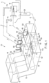
- FIG. 1 schematically shows a machine tool 1 which performs machine work such as cutting or grinding, and a filtration device 10.
- An example of the machine tool 1 includes a low-pressure-side supply system 2 and a high-pressure-side supply system 3.
- the low-pressure-side supply system 2 supplies a liquid with a relatively low pressure (for example, less than 1 MPa) to a first liquid use portion 1a.
- the high-pressure-side supply system 3 supplies a liquid with a relatively high pressure (for example, 1.5 to 3 MPa) to a second liquid use portion 1b.
- the low-pressure-side supply system 2 jets a liquid (for example, a shower coolant) to a workpiece W or its vicinity.
- the high-pressure-side supply system 3 supplies a liquid (for example, a through-spindle coolant) with high pressure to a narrow channel formed in a tool T. Since the liquid with high pressure flows in the channel having a small cross-sectional area, the high-pressure-side supply system 3 needs to supply a liquid filtered with high accuracy.
- Liquid Q1 discharged from the first liquid use portion 1a and the second liquid use portion 1b contains substances to be eliminated such as shavings and fine particles.
- liquid Q1 is supplied to the filtration device 10 via a return channel 4.
- the filtration device 10 is explained below.
- FIG. 1 shows the outline of the filtration device 10.
- FIG. 2 is a plan view of the filtration device 10.
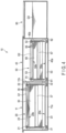
- FIG. 3 is a cross-sectional view along the line F3-F3 of FIG. 2 .
- FIG. 4 is a cross-sectional view along the line F4-F4 of FIG. 3 .
- FIG. 5 is a perspective view showing a part of the filtration device 10.
- the filtration device 10 includes a primary conveyer tank 11, a primary drum filter 30, a secondary conveyer tank 40, a secondary drum filter 60, a driver 70, a first clean tank 80, a first pump 85, a second clean tank 90, a second pump 95, etc.
- the primary conveyer tank 11 comprises a liquid inlet 12 and a sludge scraping portion 13.
- Liquid Q1 which should be filtered and is supplied from the machine tool 1 is supplied to the primary conveyer tank 11 via the liquid inlet 12.
- the sludge scraping portion 13 extend obliquely upward from an end portion of the primary conveyer tank 11.
- a sludge discharge portion 14 is formed on the top.
- a first conveyer 20 is provided in the primary conveyer tank 11.
- the first conveyer 20 is provided in a range from a bottom portion 11a of the primary conveyer tank 11 to the sludge discharge portion 14 via the sludge scraping portion 13.
- the first conveyer 20 comprises a pair of chains 21 and 22, and a plurality of scrapers 23 attached to the chains 21 and 22.
- the chains 21 and 22 are wound around a pair of first drive sprockets 25 and 26, and guide members 27 and 28.
- Chain tensioners 29 for adjusting the tension of the chains 21 and 22 are provided in the sludge scraping portion 13.
- a lower portion 20a of the first conveyer 20 moves to the sludge discharge portion 14 along the bottom portion 11a of the primary conveyer tank 11 and the bottom surface of the sludge scraping portion 13.
- the sludge on the bottom portion 11a of the primary conveyer tank 11, such as shavings, is conveyed to the sludge discharge portion 14 by the scrapers 23 of the first conveyer 20.
- a collection box is provided under the sludge discharge portion 14. The sludge conveyed to the sludge discharge portion 14 falls to the collection box.
- the primary drum filter 30 is provided in the primary conveyer tank 11.
- the primary drum filter 30 is completely immersed in liquid Q1.
- Sprockets 31 and 32 are provided at the both ends of the primary drum filter 30.
- the sprockets 31 and 32 are engaged with the chains 21 and 22 of an upper portion 20b of the first conveyer 20.
- the number of primary drum filters 30 is not limited to one.
- a plurality of primary drum filters 30 may be provided based on the capacity of filtration.
- the primary drum filter 30 may be obtained by shaping a stainless steel punching metal having a thickness of 0.5 mm into a cylindrical form.
- the primary drum filter 30 comprises a large number of primary flow holes 35 (only partially shown in FIG. 2 and FIG. 4 ).
- the diameter of the primary drum filter 30 is, for example, ⁇ 150 mm.
- the hole diameter of each primary flow hole 35 is, for example, ⁇ 0.5 mm or ⁇ 0.7 mm.
- Liquid Q1 in the primary conveyer tank 11 flows through the primary flow holes 35 from the outer circumferential side to the inner circumferential side of the primary drum filter 30. In this way, liquid Q1 is primarily filtered.
- a scraping plate 37 is in contact with the circumferential surface of the primary drum filter 30.
- the secondary conveyer tank 40 is adjacent to the primary conveyer tank 11.
- a first opening 41 is formed in a partition wall 11b formed between the primary conveyer tank 11 and the secondary conveyer tank 40.
- the secondary conveyer tank 40 communicates with the inside of the primary drum filter 30 via the first opening 41.
- clean liquid Q2 obtained by the filtration by the primary drum filter 30 flows into the secondary conveyer tank 40.
- the height of a bottom portion 40a of the secondary conveyer tank 40 is substantially the same as that of the bottom portion 11a of the primary conveyer tank 11.
- a sludge scraping portion 43 is formed in the secondary conveyer tank 40.
- the sludge scraping portion 43 extend obliquely upward from an end portion of the secondary conveyer tank 40 in a manner similar to that of the sludge scraping portion 13 of the primary conveyer tank 11.
- a sludge discharge portion 44 is formed on the top of the sludge scraping portion 43.
- a second conveyer 50 is provided in the secondary conveyer tank 40.
- the second conveyer 50 is provided in a range from the bottom portion 40a of the secondary conveyer tank 40 to the sludge discharge portion 44 via the sludge scraping portion 43.
- the second conveyer 50 comprises a pair of chains 51 and 52, and a plurality of scrapers 53.
- the scrapers 53 are attached to the chains 51 and 52.
- the chains 51 and 52 are wound around a pair of second drive sprockets 55 and 56, and guide members 57 and 58.
- Chain tensioners 59 for adjusting the tension of the chains 51 and 52 are provided in the sludge scraping portion 43.
- a lower portion 50a of the second conveyer 50 moves to the sludge discharge portion 44 along the bottom portion 40a of the secondary conveyer tank 40 and the bottom surface of the sludge scraping portion 43.
- a collection box is provided under the sludge discharge portion 44.
- the sludge on the bottom portion 40a of the secondary conveyer tank 40 such as shavings, is conveyed to the sludge discharge portion 44 by the scrapers 53 of the second conveyer 50.
- the sludge conveyed to the sludge discharge portion 44 falls to the collection box.
- the secondary drum filter 60 is provided in the secondary conveyer tank 40.
- the secondary drum filter 60 is completely immersed in clean liquid Q2.
- Sprockets 61 and 62 are provided at the both ends of the secondary drum filter 60.
- the sprockets 61 and 62 are engaged with the chains 51 and 52 of an upper portion 50b of the second conveyer 50.
- the upper surface of the secondary drum filter 60 is lower than the upper surface of the primary drum filter 30.
- the number of secondary drum filters 60 is not limited to one.
- a plurality of secondary drum filters 60 may be provided based on the capacity of filtration.
- the secondary drum filter 60 may be obtained by shaping a stainless steel thin plate having a thickness of 0.2 mm into a cylindrical form.
- the secondary drum filter 60 comprises a large number of secondary flow holes 65 (only partially shown in FIG. 4 ) formed by photo-etching.
- the diameter of the secondary drum filter 60 is less than that of the primary drum filter 30.
- the diameter of the secondary drum filter 60 is, for example, ⁇ 100 mm.
- each secondary flow hole 65 is less than that of each primary flow hole 35.
- the hole diameter of each secondary flow hole 65 is ⁇ 0.2 mm.
- the total opening area of the secondary flow holes 65 is less than that of the primary flow holes 35.
- the driver 70 comprises a single motor 71 (shown in FIG. 2 ), and a drive shaft 72 rotated by the motor 71.
- the drive shaft 72 comprises a single shaft body 73, a pair of first drive sprockets 25 and 26 which drive the first conveyer 20, and a pair of second drive sprockets 55 and 56 which drive the second conveyer 50.
- the drive sprockets 25, 26, 55 and 56 are fixed to the shaft body 73.
- the torque of the motor 71 is input from an end of the drive shaft 72. As all the drive sprockets 25, 26, 55 and 56 are simultaneously rotated by the torque, the structure of the driver 70 is simplified.
- the first clean tank 80 communicates with the secondary conveyer tank 40 via a communication opening 81.
- the communication opening 81 is formed in a partition wall 40b between the first clean tank 80 and the secondary conveyer tank 40. Clean liquid Q2 in the secondary conveyer tank 40 flows into the first clean tank 80 via the communication opening 81.
- An oil eliminating device (oil skimmer) 82 which eliminates the oil film floating on the liquid level
- a liquid level gauge 83 which detects the position of the liquid level of clean liquid Q2
- the first pump (low-pressure pump) 85 are provided in the first clean tank 80.
- the first pump 85 has a function for supplying clean liquid Q2 in the first clean tank 80 to the low-pressure-side supply system 2 (shown in FIG. 1 ).
- the second clean tank 90 is adjacent to the secondary conveyer tank 40.
- the capacity of the second clean tank 90 is less than that of the first clean tank 80.
- the second clean tank 90 communicates with the inside of the secondary drum filter 60 via a second opening 91.
- the second opening 91 is formed in the partition wall 40b between the second clean tank 90 and the secondary conveyer tank 40.
- Clean liquid Q2 in the secondary conveyer tank 40 is secondary filtered by the secondary drum filter 60 to be super clean liquid Q3.
- Super clean liquid Q3 obtained by the secondary filtration by the secondary drum filter 60 flows into the second clean tank 90 via the second opening 91.
- a liquid level gauge 92 which detects the position of the liquid level of super clean liquid Q3 is provided in the second clean tank 90.
- the second pump (high-pressure pump) 95 is provided in the second clean tank 90.
- the second pump 95 supplies super clean liquid Q3 in the second clean tank 90 to the high-pressure-side supply system 3 (shown in FIG. 1 ) at a pressure higher than that of the first pump 85.
- the discharge capacity of the second pump 95 is less than that of the first pump 85.
- Liquid Q1 discharged from the machine tool 1 is supplied to the primary conveyer tank 11 via the return channel 4 and the liquid inlet 12.
- the sludge containing shavings, etc., on the bottom portion 11a of the primary conveyer tank 11 is conveyed to the sludge discharge portion 14 by the scrapers 23 of the first conveyer 20.
- Liquid Q1 in the primary conveyer tank 11 is primarily filtered by the primary drum filter 30, and flows into the secondary conveyer tank 40 via the first opening 41.
- the sludge attached to the primary drum filter 30 is scraped off by the scraping plate 37.
- Liquid Q1 in the primary conveyer tank 11 is filtered by passing through the primary drum filter 30 from the external side to the internal side, and flows into the secondary conveyer tank 40 as clean liquid Q2.
- Channel resistance is generated when liquid Q1 passes through the primary flow holes 35 of the primary drum filter 30.
- the liquid level of clean liquid Q2 having flowed into the secondary conveyer tank 40 is lower than that of liquid Q1 in the primary conveyer tank 11.
- the diameter of the secondary drum filter 60 is less than that of the primary drum filter 30.
- the upper surface of the secondary drum filter 60 is lower than the upper surface of the primary drum filter 30. In this way, the exposure of the upper surface of the secondary drum filter 60 from clean liquid Q2 is avoided.
- Clean liquid Q2 having flowed into the secondary conveyer tank 40 mostly flows into the first clean tank 80 via the communication opening 81.
- Clean liquid Q2 having flowed into the first clean tank 80 is sent to the low-pressure-side supply system 2 by the first pump 85.
- the amount supplied by the first pump 85 is, for example, 200 L/min.
- the sludge on the bottom portion 40a of the secondary conveyer tank 40 is conveyed to the sludge discharge portion 44 by the scrapers 53 of the second conveyer 50.
- the sludge attached to the secondary drum filter 60 is scraped off by the scraping plate 67.
- the scrapers 53 of the upper portion 50b of the second conveyer 50 move to the side under the liquid level of clean liquid Q2 as the scrapers 53 pass the vicinity of the liquid level.
- the sludge floating around the liquid level of clean liquid Q2 can be guided to the side under the liquid level by the scrapers 53. In this way, it is possible to prevent sludge from continuing to float around the liquid level.
- clean liquid Q2 can be effectively further (secondarily) filtered.
- Clean liquid Q2 in the secondary conveyer tank 40 is partially secondarily filtered by the secondary drum filter 60, and flows into the second clean tank 90 via the second opening 91.
- Liquid (super clean liquid) Q3 having flowed into the second clean tank 90 is sent to the high-pressure-side supply system 3 by the second pump 95.
- the amount supplied by the second pump 95 is, for example, 20 L/min.
- the first pump 85 pumps up a large amount of clean liquid Q2 having flowed into the first clean tank 80 from the secondary conveyer tank 40, and supplies it to the low-pressure-side supply system 2.
- the pressure of the first pump 85 is low.
- the second pump 95 supplies a relatively small amount of super clean liquid Q3 having flowed into the second clean tank 90 via the secondary drum filter 60 to the high-pressure-side supply system 3.
- the pressure of the second pump 95 is high.
- the discharge of the second pump 95 is less.
- the second clean tank 90 for the second pump 95 in which the discharge is less has a small capacity suitable for the discharge of the second pump 95. This structure can contribute to the reduction in the size of the filtration device 10. Thus, the floor area of a plant can be effectively used.
- the filtration device 10 of the present embodiment is capable of supplying clean liquid Q2 obtained by the primary filtration by the primary drum filter 30 to the low-pressure-side supply system 2 of a machine tool, etc., by the first pump 85.
- Super clean liquid Q3 obtained by the further secondary filtration by the secondary drum filter 60 can be supplied to the high-pressure-side supply system 3 by the second pump 95.
- a large amount of clean liquid Q2 obtained by the primary filtration can be supplied to the liquid use portion of the low-pressure system in which the use amount is great.
- a small amount of super clean liquid Q3 obtained by the secondary filtration with a high filtration accuracy can be supplied to, at high pressure, the liquid use portion of the high-pressure system with a small channel cross-sectional area and a small use amount.
- the primary conveyer tank 11 is purified on a steady basis by the first conveyer 20 and the primary drum filter 30.
- the secondary conveyer tank 40 is purified on a steady basis by the second conveyer 50 and the secondary drum filter 60.
- the primary conveyer tank, the secondary conveyer tank, the primary drum filter, the secondary drum filter, the first clean tank, the second clean tank, the first pump, the second pump and the like included in the filtration device may be changed in various ways within the scope of the appended claims.
Description
- The present invention described herein relate generally to a filtration device for purifying a liquid containing shavings, fine particles, etc., such as a coolant used for, for example, a machine tool.
- In machine tools which perform mechanical processing such as cutting or grinding, a coolant is supplied to a workpiece or a tool. Shavings, fine particles and the like are mixed in the used coolant. To purify and reuse such a coolant, various filtration devices have been conventionally suggested. For example, each of the filtration devices disclosed in the following
Patent Literatures -
- Patent Literature 1:
JP 2904334 B - Patent Literature 2:
JP 3389126 B - Patent Literature 3:
JP H11 239704 A - To jet a coolant through a narrow channel formed in a tool, etc., the coolant needs to be supplied to the channel by a high-pressure pump. However, the narrow channel is easily clogged with foreign substances such as particles. When a filter is provided in the pump to prevent clogging, the structure of the pump becomes complicated, and the filter needs to be regularly changed. The used filter has to be processed as industrial waste. Thus, the cost is high. In conventional filtration devices, the unclean coolant discharged from a machine tool is supplied to and stored in a filter tank. Thus, it is impossible to avoid the storage of sludge in the filter tank. The inside of the tank needs to be frequently cleaned. The conventional filtration devices require great care.
- The object of the present invention is to provide a filtration device which has high filtration accuracy, does not require the cleaning of a tank and is capable of supplying a clean liquid obtained by primary filtration and a super clean liquid obtained by secondary filtration to a low-pressure-side supply system or high-pressure-side supply system of a machine tool, etc., depending on the need.
- According to the invention, a filtration device, according to
claim 1, comprises a primary conveyer tank, a primary drum filter, a secondary conveyer tank, a secondary drum filter, a driver, a first clean tank, a first pump, a second clean tank and a second pump. - The primary conveyer tank comprises a first conveyer, the first conveyer is provided in a range from a bottom portion of the primary conveyer tank to a first sludge discharge portion via a first sludge scraping portion. A liquid to be filtered is supplied to the primary conveyer tank. The primary drum filter is provided in a liquid of the primary conveyer tank, and is rotated by a chain of the first conveyer. The primary drum filter comprises a primary flow hole for filtering the liquid in the primary conveyer tank.
- The secondary conveyer tank is adjacent to the primary conveyer tank. The secondary conveyer tank comprises a second conveyer. The second conveyer is provided in a range from a bottom portion of the secondary conveyer tank to a second sludge discharge portion via a second sludge scraping portion. The secondary conveyer tank communicates with inside of the primary drum filter via a first opening formed between the secondary conveyer tank and the primary conveyer tank. A clean liquid obtained by first filtration by the primary drum filter flows into the secondary conveyer tank. The secondary drum filter is provided in the clean liquid in the secondary conveyer tank, and is rotated by a chain of the second conveyer. The secondary drum filter comprises a secondary flow hole for further filtering the clean liquid in the secondary conveyer tank. The driver drives the first conveyer and the second conveyer.
- The first clean tank communicates with the secondary conveyer tank. The clean liquid in the secondary conveyer tank flows into the first clean tank. The first pump supplies the clean liquid in the first clean tank to a first liquid use portion. The second clean tank is adjacent to the secondary conveyer tank. The second clean tank communicates with inside of the secondary drum filter via a second opening formed between the second clean tank and the secondary conveyer tank. A super clean liquid obtained by secondary filtration by the secondary drum filter flows into the second clean tank. The second pump supplies the super clean liquid in the second clean tank to a second liquid use portion.
- An example of the first pump is a low-pressure pump for supplying the clean liquid to the liquid use portion on the low-pressure side. An example of the liquid use portion on the low-pressure side is the shower coolant jet portion of a machine tool. An example of the second pump is a high-pressure pump for supplying the super clean liquid to the liquid use portion on the high-pressure side at a pressure higher than the pressure of the first pump. An example of the liquid use portion on the high-pressure side is the through-spindle coolant jet portion of a machine tool.
- According to the filtration device of the present invention, the clean liquid obtained by the primary filtration by the primary drum filter can be supplied to the low-pressure-side supply system of a machine tool, etc. The super clean liquid obtained by the filtration with higher accuracy by the secondary drum filter can be supplied to the high-pressure-side supply system. The filtering accuracy is high, and there is no need to frequently clean the tank. Thus, the maintenance is easy.
-
-
FIG. 1 is a perspective view schematically showing a filtration device according to one embodiment. -
FIG. 2 is a plan view of the filtration device shown inFIG. 1 . -
FIG. 3 is a cross-sectional view of the filtration device along the line F3-F3 ofFIG. 2 . -
FIG. 4 is a cross-sectional view of the filtration device along the line F4-F4 ofFIG. 3 . -
FIG. 5 is a perspective view showing a part of the filtration device. - With reference to
FIG. 1 to FIG. 5 , this specification hereinafter explains a filtration device according to one embodiment of the present invention. -
FIG. 1 schematically shows amachine tool 1 which performs machine work such as cutting or grinding, and afiltration device 10. An example of themachine tool 1 includes a low-pressure-side supply system 2 and a high-pressure-side supply system 3. The low-pressure-side supply system 2 supplies a liquid with a relatively low pressure (for example, less than 1 MPa) to a firstliquid use portion 1a. The high-pressure-side supply system 3 supplies a liquid with a relatively high pressure (for example, 1.5 to 3 MPa) to a second liquid use portion 1b. The low-pressure-side supply system 2 jets a liquid (for example, a shower coolant) to a workpiece W or its vicinity. - On the other hand, the high-pressure-side supply system 3 supplies a liquid (for example, a through-spindle coolant) with high pressure to a narrow channel formed in a tool T. Since the liquid with high pressure flows in the channel having a small cross-sectional area, the high-pressure-side supply system 3 needs to supply a liquid filtered with high accuracy. Liquid Q1 discharged from the first
liquid use portion 1a and the second liquid use portion 1b contains substances to be eliminated such as shavings and fine particles. To filter liquid Q1, liquid Q1 is supplied to thefiltration device 10 via areturn channel 4. - The
filtration device 10 is explained below. -
FIG. 1 shows the outline of thefiltration device 10.FIG. 2 is a plan view of thefiltration device 10.FIG. 3 is a cross-sectional view along the line F3-F3 ofFIG. 2 .FIG. 4 is a cross-sectional view along the line F4-F4 ofFIG. 3 .FIG. 5 is a perspective view showing a part of thefiltration device 10. - The
filtration device 10 includes aprimary conveyer tank 11, aprimary drum filter 30, asecondary conveyer tank 40, asecondary drum filter 60, adriver 70, a firstclean tank 80, afirst pump 85, a secondclean tank 90, asecond pump 95, etc. - The
primary conveyer tank 11 comprises aliquid inlet 12 and asludge scraping portion 13. Liquid Q1 which should be filtered and is supplied from themachine tool 1 is supplied to theprimary conveyer tank 11 via theliquid inlet 12. Thesludge scraping portion 13 extend obliquely upward from an end portion of theprimary conveyer tank 11. Asludge discharge portion 14 is formed on the top. - A
first conveyer 20 is provided in theprimary conveyer tank 11. Thefirst conveyer 20 is provided in a range from abottom portion 11a of theprimary conveyer tank 11 to thesludge discharge portion 14 via thesludge scraping portion 13. Thefirst conveyer 20 comprises a pair ofchains scrapers 23 attached to thechains chains first drive sprockets members Chain tensioners 29 for adjusting the tension of thechains sludge scraping portion 13. - A
lower portion 20a of thefirst conveyer 20 moves to thesludge discharge portion 14 along thebottom portion 11a of theprimary conveyer tank 11 and the bottom surface of thesludge scraping portion 13. The sludge on thebottom portion 11a of theprimary conveyer tank 11, such as shavings, is conveyed to thesludge discharge portion 14 by thescrapers 23 of thefirst conveyer 20. A collection box is provided under thesludge discharge portion 14. The sludge conveyed to thesludge discharge portion 14 falls to the collection box. - The
primary drum filter 30 is provided in theprimary conveyer tank 11. Theprimary drum filter 30 is completely immersed in liquid Q1.Sprockets primary drum filter 30. Thesprockets chains upper portion 20b of thefirst conveyer 20. Thus, when thefirst conveyer 20 moves in the direction of arrow A1 ofFIG. 5 , theprimary drum filter 30 rotates in the direction of arrow A2. The number of primary drum filters 30 is not limited to one. A plurality of primary drum filters 30 may be provided based on the capacity of filtration. - For example, the
primary drum filter 30 may be obtained by shaping a stainless steel punching metal having a thickness of 0.5 mm into a cylindrical form. Theprimary drum filter 30 comprises a large number of primary flow holes 35 (only partially shown inFIG. 2 andFIG. 4 ). The diameter of theprimary drum filter 30 is, for example, ϕ150 mm. The hole diameter of eachprimary flow hole 35 is, for example, ϕ0.5 mm or ϕ0.7 mm. Liquid Q1 in theprimary conveyer tank 11 flows through the primary flow holes 35 from the outer circumferential side to the inner circumferential side of theprimary drum filter 30. In this way, liquid Q1 is primarily filtered. A scrapingplate 37 is in contact with the circumferential surface of theprimary drum filter 30. - The
secondary conveyer tank 40 is adjacent to theprimary conveyer tank 11. Afirst opening 41 is formed in apartition wall 11b formed between theprimary conveyer tank 11 and thesecondary conveyer tank 40. Thesecondary conveyer tank 40 communicates with the inside of theprimary drum filter 30 via thefirst opening 41. Thus, clean liquid Q2 obtained by the filtration by theprimary drum filter 30 flows into thesecondary conveyer tank 40. - The height of a
bottom portion 40a of thesecondary conveyer tank 40 is substantially the same as that of thebottom portion 11a of theprimary conveyer tank 11. Asludge scraping portion 43 is formed in thesecondary conveyer tank 40. Thesludge scraping portion 43 extend obliquely upward from an end portion of thesecondary conveyer tank 40 in a manner similar to that of thesludge scraping portion 13 of theprimary conveyer tank 11. Asludge discharge portion 44 is formed on the top of thesludge scraping portion 43. - A
second conveyer 50 is provided in thesecondary conveyer tank 40. Thesecond conveyer 50 is provided in a range from thebottom portion 40a of thesecondary conveyer tank 40 to thesludge discharge portion 44 via thesludge scraping portion 43. Thesecond conveyer 50 comprises a pair ofchains scrapers 53. Thescrapers 53 are attached to thechains chains second drive sprockets members Chain tensioners 59 for adjusting the tension of thechains sludge scraping portion 43. - A
lower portion 50a of thesecond conveyer 50 moves to thesludge discharge portion 44 along thebottom portion 40a of thesecondary conveyer tank 40 and the bottom surface of thesludge scraping portion 43. A collection box is provided under thesludge discharge portion 44. The sludge on thebottom portion 40a of thesecondary conveyer tank 40, such as shavings, is conveyed to thesludge discharge portion 44 by thescrapers 53 of thesecond conveyer 50. The sludge conveyed to thesludge discharge portion 44 falls to the collection box. - The
secondary drum filter 60 is provided in thesecondary conveyer tank 40. Thesecondary drum filter 60 is completely immersed in clean liquid Q2.Sprockets secondary drum filter 60. Thesprockets chains upper portion 50b of thesecond conveyer 50. Thus, when thesecond conveyer 50 moves in the direction of arrow B1 ofFIG. 3 , thesecondary drum filter 60 rotates in the direction of arrow B2. The upper surface of thesecondary drum filter 60 is lower than the upper surface of theprimary drum filter 30. The number of secondary drum filters 60 is not limited to one. A plurality of secondary drum filters 60 may be provided based on the capacity of filtration. - For example, the
secondary drum filter 60 may be obtained by shaping a stainless steel thin plate having a thickness of 0.2 mm into a cylindrical form. Thesecondary drum filter 60 comprises a large number of secondary flow holes 65 (only partially shown inFIG. 4 ) formed by photo-etching. The diameter of thesecondary drum filter 60 is less than that of theprimary drum filter 30. The diameter of thesecondary drum filter 60 is, for example, ϕ100 mm. - The hole diameter of each
secondary flow hole 65 is less than that of eachprimary flow hole 35. For example, the hole diameter of eachsecondary flow hole 65 is ϕ0.2 mm. The total opening area of the secondary flow holes 65 is less than that of the primary flow holes 35. Clean liquid Q2 in thesecondary conveyer tank 40 is filtered by flowing through the secondary flow holes 65 from the outer circumferential side to the inner circumferential side of thesecondary drum filter 60. A scrapingplate 67 is in contact with the circumferential surface of thesecondary drum filter 60. - The
driver 70 comprises a single motor 71 (shown inFIG. 2 ), and adrive shaft 72 rotated by themotor 71. Thedrive shaft 72 comprises asingle shaft body 73, a pair offirst drive sprockets first conveyer 20, and a pair ofsecond drive sprockets second conveyer 50. The drive sprockets 25, 26, 55 and 56 are fixed to theshaft body 73. In the present embodiment, the torque of themotor 71 is input from an end of thedrive shaft 72. As all thedrive sprockets driver 70 is simplified. - The first
clean tank 80 communicates with thesecondary conveyer tank 40 via acommunication opening 81. Thecommunication opening 81 is formed in apartition wall 40b between the firstclean tank 80 and thesecondary conveyer tank 40. Clean liquid Q2 in thesecondary conveyer tank 40 flows into the firstclean tank 80 via thecommunication opening 81. An oil eliminating device (oil skimmer) 82 which eliminates the oil film floating on the liquid level, aliquid level gauge 83 which detects the position of the liquid level of clean liquid Q2, and the first pump (low-pressure pump) 85 are provided in the firstclean tank 80. Thefirst pump 85 has a function for supplying clean liquid Q2 in the firstclean tank 80 to the low-pressure-side supply system 2 (shown inFIG. 1 ). - The second
clean tank 90 is adjacent to thesecondary conveyer tank 40. The capacity of the secondclean tank 90 is less than that of the firstclean tank 80. The secondclean tank 90 communicates with the inside of thesecondary drum filter 60 via asecond opening 91. Thesecond opening 91 is formed in thepartition wall 40b between the secondclean tank 90 and thesecondary conveyer tank 40. Clean liquid Q2 in thesecondary conveyer tank 40 is secondary filtered by thesecondary drum filter 60 to be super clean liquid Q3. Super clean liquid Q3 obtained by the secondary filtration by thesecondary drum filter 60 flows into the secondclean tank 90 via thesecond opening 91. Aliquid level gauge 92 which detects the position of the liquid level of super clean liquid Q3 is provided in the secondclean tank 90. - The second pump (high-pressure pump) 95 is provided in the second
clean tank 90. Thesecond pump 95 supplies super clean liquid Q3 in the secondclean tank 90 to the high-pressure-side supply system 3 (shown inFIG. 1 ) at a pressure higher than that of thefirst pump 85. The discharge capacity of thesecond pump 95 is less than that of thefirst pump 85. - Now, this specification explains the effects of the
filtration device 10 of the present embodiment. - Liquid Q1 discharged from the
machine tool 1 is supplied to theprimary conveyer tank 11 via thereturn channel 4 and theliquid inlet 12. The sludge containing shavings, etc., on thebottom portion 11a of theprimary conveyer tank 11 is conveyed to thesludge discharge portion 14 by thescrapers 23 of thefirst conveyer 20. Liquid Q1 in theprimary conveyer tank 11 is primarily filtered by theprimary drum filter 30, and flows into thesecondary conveyer tank 40 via thefirst opening 41. The sludge attached to theprimary drum filter 30 is scraped off by the scrapingplate 37. - Liquid Q1 in the
primary conveyer tank 11 is filtered by passing through theprimary drum filter 30 from the external side to the internal side, and flows into thesecondary conveyer tank 40 as clean liquid Q2. Channel resistance is generated when liquid Q1 passes through the primary flow holes 35 of theprimary drum filter 30. Thus, the liquid level of clean liquid Q2 having flowed into thesecondary conveyer tank 40 is lower than that of liquid Q1 in theprimary conveyer tank 11. The diameter of thesecondary drum filter 60 is less than that of theprimary drum filter 30. Further, the upper surface of thesecondary drum filter 60 is lower than the upper surface of theprimary drum filter 30. In this way, the exposure of the upper surface of thesecondary drum filter 60 from clean liquid Q2 is avoided. - Clean liquid Q2 having flowed into the
secondary conveyer tank 40 mostly flows into the firstclean tank 80 via thecommunication opening 81. Clean liquid Q2 having flowed into the firstclean tank 80 is sent to the low-pressure-side supply system 2 by thefirst pump 85. The amount supplied by thefirst pump 85 is, for example, 200 L/min. The sludge on thebottom portion 40a of thesecondary conveyer tank 40 is conveyed to thesludge discharge portion 44 by thescrapers 53 of thesecond conveyer 50. The sludge attached to thesecondary drum filter 60 is scraped off by the scrapingplate 67. - In the
secondary conveyer tank 40, thescrapers 53 of theupper portion 50b of thesecond conveyer 50 move to the side under the liquid level of clean liquid Q2 as thescrapers 53 pass the vicinity of the liquid level. The sludge floating around the liquid level of clean liquid Q2 can be guided to the side under the liquid level by thescrapers 53. In this way, it is possible to prevent sludge from continuing to float around the liquid level. Thus, clean liquid Q2 can be effectively further (secondarily) filtered. - Clean liquid Q2 in the
secondary conveyer tank 40 is partially secondarily filtered by thesecondary drum filter 60, and flows into the secondclean tank 90 via thesecond opening 91. Liquid (super clean liquid) Q3 having flowed into the secondclean tank 90 is sent to the high-pressure-side supply system 3 by thesecond pump 95. The amount supplied by thesecond pump 95 is, for example, 20 L/min. - The
first pump 85 pumps up a large amount of clean liquid Q2 having flowed into the firstclean tank 80 from thesecondary conveyer tank 40, and supplies it to the low-pressure-side supply system 2. The pressure of thefirst pump 85 is low. However, the discharge of thefirst pump 85 is great. Thesecond pump 95 supplies a relatively small amount of super clean liquid Q3 having flowed into the secondclean tank 90 via thesecondary drum filter 60 to the high-pressure-side supply system 3. The pressure of thesecond pump 95 is high. However, the discharge of thesecond pump 95 is less. In the present embodiment, the secondclean tank 90 for thesecond pump 95 in which the discharge is less has a small capacity suitable for the discharge of thesecond pump 95. This structure can contribute to the reduction in the size of thefiltration device 10. Thus, the floor area of a plant can be effectively used. - As described above, the
filtration device 10 of the present embodiment is capable of supplying clean liquid Q2 obtained by the primary filtration by theprimary drum filter 30 to the low-pressure-side supply system 2 of a machine tool, etc., by thefirst pump 85. Super clean liquid Q3 obtained by the further secondary filtration by thesecondary drum filter 60 can be supplied to the high-pressure-side supply system 3 by thesecond pump 95. A large amount of clean liquid Q2 obtained by the primary filtration can be supplied to the liquid use portion of the low-pressure system in which the use amount is great. Relatively a small amount of super clean liquid Q3 obtained by the secondary filtration with a high filtration accuracy can be supplied to, at high pressure, the liquid use portion of the high-pressure system with a small channel cross-sectional area and a small use amount. In addition, theprimary conveyer tank 11 is purified on a steady basis by thefirst conveyer 20 and theprimary drum filter 30. At the same time, thesecondary conveyer tank 40 is purified on a steady basis by thesecond conveyer 50 and thesecondary drum filter 60. Thus, there is no need to frequently clean the tanks by human resources. The necessity to provide a filter in the low-pressure-side supply system 2 or the high-pressure-side supply system 3 is reduced. Thus, the maintenance is easy. - To implement the present invention, as a matter of course, the primary conveyer tank, the secondary conveyer tank, the primary drum filter, the secondary drum filter, the first clean tank, the second clean tank, the first pump, the second pump and the like included in the filtration device may be changed in various ways within the scope of the appended claims.
- 1a···First liquid use portion, 1b···Second liquid use portion, 2···Low-pressure-side supply system, 3···High-pressure-side supply system, Q1···Liquid to be filtered, Q2···Liquid obtained by primary filtration (clean liquid), Q3···Liquid obtained by secondary filtration (super clean liquid), 10···Filtration device, 11···Primary conveyer tank, 11a···Bottom portion, 20···First conveyer, 21, 22···Chain, 23···Scraper, 25, 26···First drive sprocket, 30···Primary drum filter, 35···Primary flow hole, 40···Secondary conveyer tank, 40a···Bottom portion, 41···First opening, 50···Second conveyer, 51, 52···Chain, 53···Scraper, 55, 56···Second drive sprocket, 60···Secondary drum filter, 65···Secondary flow hole, 70···Driver, 71···Motor, 72···Drive shaft, 73···Shaft body, 80···First clean tank, 85···First pump, 90···Second clean tank, 91···Second opening, 95···Second pump
Claims (5)
- A filtration device comprising:a primary conveyer tank (11) supplied with a liquid (Q1) to be filtered;a first conveyer (20) provided in the primary conveyer tank (11), the first conveyer (20) being provided in a range from a bottom portion (11a) of the primary conveyer tank (11) to a first sludge discharge portion (14) via a first sludge scraping portion (13);a primary drum filter (30) provided in the liquid of the primary conveyer tank (11), rotated by a chain (21, 22) of the first conveyer (20), and comprising a primary flow hole (35) for filtering the liquid (Q1) in the primary conveyer tank (11);a secondary conveyer tank (40) adjacent to the primary conveyer tank (11), and communicating with inside of the primary drum filter (30) via a first opening (41) formed between the secondary conveyer tank (40) and the primary conveyer tank (11), wherein a clean liquid (Q2) obtained by filtration by the primary drum filter (30) flows into the secondary conveyer tank (40);characterized by further comprising:a second conveyer (50) provided in the secondary conveyer tank (40), the second conveyer (50) being provided in a range from a bottom portion (40a) of the secondary conveyer tank (40) to a second sludge discharge portion (44) via a second sludge scraping portion (43);a secondary drum filter (60) provided in the clean liquid (Q2) of the secondary conveyer tank (40), rotated by a chain (51, 52) of the second conveyer (50), and comprising a secondary flow hole (65) for further filtering the clean liquid (Q2) in the secondary conveyer tank (40);a driver (70) which drives the first conveyer (20) and the second conveyer (50);a first clean tank (80) communicating with the secondary conveyer tank (40) via a communication opening (81) which is formed in a partition wall (40b) between the secondary conveyer tank (40) and the first clean tank (80), wherein the clean liquid (Q2) in the secondary conveyer tank (40) flows into the first clean tank (80) via the communication opening (81);a first pump (85) which supplies the clean liquid (Q2) in the first clean tank (80) to a first liquid use portion (1a);a second clean tank (90) adjacent to the secondary conveyer tank (40), and communicating with inside of the secondary drum filter (60) via a second opening (91) formed in the partition wall (40b) formed between the second clean tank (90) and the secondary conveyer tank (40), wherein a super clean liquid (Q3) obtained by filtration by the secondary drum filter (60) flows into the second clean tank (90) via the second opening (91); anda second pump (95) which supplies the super clean liquid (Q3) in the second clean tank (90) to a second liquid use portion (1b).
- The filtration device of Claim 1, characterized in that
the first pump (85) is a low-pressure pump which supplies the clean liquid (Q2) to a low-pressure-side supply system (2), and the second pump (95) is a high-pressure pump which supplies the super clean liquid (Q3) to a high-pressure supply system (3) at a pressure higher than a pressure of the first pump (85). - The filtration device of Claim 1, characterized in that
the driver (70) comprises:a drive shaft (72) comprising a shaft body (73), a pair of first drive sprockets (25, 26) provided in the shaft body (73) and driving the first conveyer (20), and a pair of second drive sprockets (55, 56) provided in the shaft body (73) and driving the second conveyer (50); anda motor (71) provided at an end of the drive shaft (72), and simultaneously rotating the first drive sprockets (25, 26) and the second drive sprockets (55, 56) by inputting torque from the end of the drive shaft (72). - The filtration device of Claim 1, characterized in thata diameter of the secondary drum filter (60) is less than a diameter of the primary drum filter (30),a hole diameter of the secondary flow hole (65) is less than a hole diameter of the primary flow hole (35), anda total opening area of the secondary flow hole (65) is less than a total opening area of the primary flow hole (35).
- The filtration device of Claim 4, characterized in that
the secondary drum filter (60) is provided in the secondary conveyer tank (40) such that an upper surface of the secondary drum filter (60) is lower than an upper surface of the primary drum filter (30).
Applications Claiming Priority (2)
| Application Number | Priority Date | Filing Date | Title |
|---|---|---|---|
| JP2015254072A JP6007309B1 (en) | 2015-12-25 | 2015-12-25 | Filtration device |
| PCT/JP2016/080819 WO2017110219A1 (en) | 2015-12-25 | 2016-10-18 | Filtration device |
Publications (3)
| Publication Number | Publication Date |
|---|---|
| EP3395498A1 EP3395498A1 (en) | 2018-10-31 |
| EP3395498A4 EP3395498A4 (en) | 2019-08-14 |
| EP3395498B1 true EP3395498B1 (en) | 2023-03-15 |
Family
ID=57123278
Family Applications (1)
| Application Number | Title | Priority Date | Filing Date |
|---|---|---|---|
| EP16878117.7A Active EP3395498B1 (en) | 2015-12-25 | 2016-10-18 | Filtration device |
Country Status (9)
| Country | Link |
|---|---|
| US (1) | US10561970B2 (en) |
| EP (1) | EP3395498B1 (en) |
| JP (1) | JP6007309B1 (en) |
| KR (1) | KR102122995B1 (en) |
| CN (1) | CN108430694B (en) |
| MY (1) | MY191041A (en) |
| PH (1) | PH12018550094A1 (en) |
| SG (1) | SG11201805178QA (en) |
| WO (1) | WO2017110219A1 (en) |
Families Citing this family (6)
| Publication number | Priority date | Publication date | Assignee | Title |
|---|---|---|---|---|
| JP6653677B2 (en) * | 2017-03-24 | 2020-02-26 | Dmg森精機株式会社 | Chip conveyors and machine tools |
| JP6996105B2 (en) * | 2017-04-05 | 2022-01-17 | ブラザー工業株式会社 | Cleaning equipment and cleaning method |
| JP6375424B1 (en) * | 2017-09-13 | 2018-08-15 | 株式会社ブンリ | Filtration device |
| US20200078894A1 (en) * | 2018-09-07 | 2020-03-12 | Manufacturing Productivity Systems | Coolant filtration system |
| JP7133736B1 (en) * | 2022-03-10 | 2022-09-08 | Dmg森精機株式会社 | Coolant supply device |
| JP7274673B1 (en) | 2023-01-10 | 2023-05-16 | ユアサネオテック株式会社 | Program and machine tool system |
Family Cites Families (16)
| Publication number | Priority date | Publication date | Assignee | Title |
|---|---|---|---|---|
| US2904334A (en) | 1956-10-15 | 1959-09-15 | Eastman Kodak Co | Sheet feeding and turning apparatus |
| GB1053917A (en) | 1964-02-05 | |||
| JP3004556B2 (en) | 1994-03-03 | 2000-01-31 | 株式会社シスト | Separation filtration method and separation filtration device |
| JP2904334B2 (en) | 1995-02-14 | 1999-06-14 | 株式会社シスト | Filtration device |
| JPH09300171A (en) * | 1996-05-17 | 1997-11-25 | Shisuto:Kk | Filtering device and filtering system |
| JP3720559B2 (en) * | 1997-12-26 | 2005-11-30 | キタムラ機械株式会社 | Cutting oil filtration device |
| US6093315A (en) * | 1998-02-19 | 2000-07-25 | Advanced Filtration Concepts | Sealing arrangement for filter belt |
| JP3389126B2 (en) | 1998-12-17 | 2003-03-24 | モスニック株式会社 | Filtration device |
| JP3472733B2 (en) * | 1999-05-10 | 2003-12-02 | 株式会社ブンリ | Processing equipment for cutting chips |
| JP3648177B2 (en) * | 2001-06-29 | 2005-05-18 | 株式会社マコト | Environmentally friendly coolant system |
| JP3805270B2 (en) * | 2002-03-14 | 2006-08-02 | 株式会社牧野フライス製作所 | Machine fluid supply equipment for machine tools |
| DE10223291A1 (en) * | 2002-05-24 | 2003-12-11 | Mayfran Int Bv | Device for receiving and separating chips and coolant (overflow) from machine tools |
| EP1992448B1 (en) * | 2006-02-23 | 2011-04-13 | Bunri Incorporation | Filtering device |
| JP4830043B1 (en) | 2010-10-29 | 2011-12-07 | 株式会社ブンリ | Filtration device |
| JP5526253B1 (en) * | 2013-04-12 | 2014-06-18 | 株式会社ブンリ | Filtration device |
| JP5771733B1 (en) * | 2014-11-27 | 2015-09-02 | 株式会社ブンリ | Sprocket direct drive shaft for filtration equipment |
-
2015
- 2015-12-25 JP JP2015254072A patent/JP6007309B1/en active Active
-
2016
- 2016-10-18 WO PCT/JP2016/080819 patent/WO2017110219A1/en active Application Filing
- 2016-10-18 SG SG11201805178QA patent/SG11201805178QA/en unknown
- 2016-10-18 MY MYPI2018001051A patent/MY191041A/en unknown
- 2016-10-18 CN CN201680075606.9A patent/CN108430694B/en active Active
- 2016-10-18 KR KR1020187017780A patent/KR102122995B1/en active IP Right Grant
- 2016-10-18 EP EP16878117.7A patent/EP3395498B1/en active Active
-
2018
- 2018-06-06 US US16/001,464 patent/US10561970B2/en active Active
- 2018-06-14 PH PH12018550094A patent/PH12018550094A1/en unknown
Also Published As
| Publication number | Publication date |
|---|---|
| SG11201805178QA (en) | 2018-07-30 |
| CN108430694A (en) | 2018-08-21 |
| US20180280841A1 (en) | 2018-10-04 |
| EP3395498A1 (en) | 2018-10-31 |
| KR102122995B1 (en) | 2020-06-15 |
| MY191041A (en) | 2022-05-30 |
| EP3395498A4 (en) | 2019-08-14 |
| PH12018550094A1 (en) | 2019-03-11 |
| WO2017110219A1 (en) | 2017-06-29 |
| US10561970B2 (en) | 2020-02-18 |
| JP2017113854A (en) | 2017-06-29 |
| CN108430694B (en) | 2020-03-13 |
| KR20180085777A (en) | 2018-07-27 |
| JP6007309B1 (en) | 2016-10-12 |
Similar Documents
| Publication | Publication Date | Title |
|---|---|---|
| EP3395498B1 (en) | Filtration device | |
| KR20130069826A (en) | Filtration device | |
| KR0141852B1 (en) | Fractional filtration method and fractional filter | |
| EP1992448B1 (en) | Filtering device | |
| US11628386B2 (en) | Filtration device | |
| JP3648177B2 (en) | Environmentally friendly coolant system | |
| RU2707225C1 (en) | Industrial purification plant with filtering device and corresponding method | |
| JP2020114577A (en) | Water treatment device | |
| JP5526253B1 (en) | Filtration device | |
| JP4646215B2 (en) | Waste nori collection mechanism in foreign matter separation device of nori mixed liquid | |
| JP2016155193A (en) | Working fluid purification system | |
| KR20090130966A (en) | A filteration unit for supply device of metalworking fluids | |
| JP7401230B2 (en) | filtration equipment | |
| JP2006159393A (en) | Coolant filtration equipment | |
| JP2017030083A (en) | Cutting work method | |
| KR101475805B1 (en) | Prevent sedimentation coolant tank | |
| JP2020037142A (en) | Coolant filtering apparatus | |
| JP2004230468A (en) | Cutting oil filtering apparatus | |
| JP2015044277A (en) | Coolant tank |
Legal Events
| Date | Code | Title | Description |
|---|---|---|---|
| STAA | Information on the status of an ep patent application or granted ep patent |
Free format text: STATUS: THE INTERNATIONAL PUBLICATION HAS BEEN MADE |
|
| PUAI | Public reference made under article 153(3) epc to a published international application that has entered the european phase |
Free format text: ORIGINAL CODE: 0009012 |
|
| STAA | Information on the status of an ep patent application or granted ep patent |
Free format text: STATUS: REQUEST FOR EXAMINATION WAS MADE |
|
| 17P | Request for examination filed |
Effective date: 20180618 |
|
| AK | Designated contracting states |
Kind code of ref document: A1 Designated state(s): AL AT BE BG CH CY CZ DE DK EE ES FI FR GB GR HR HU IE IS IT LI LT LU LV MC MK MT NL NO PL PT RO RS SE SI SK SM TR |
|
| AX | Request for extension of the european patent |
Extension state: BA ME |
|
| DAV | Request for validation of the european patent (deleted) | ||
| DAX | Request for extension of the european patent (deleted) | ||
| A4 | Supplementary search report drawn up and despatched |
Effective date: 20190716 |
|
| RIC1 | Information provided on ipc code assigned before grant |
Ipc: B01D 33/80 20060101ALI20190710BHEP Ipc: B23Q 11/00 20060101AFI20190710BHEP Ipc: B01D 33/06 20060101ALI20190710BHEP Ipc: B01D 33/58 20060101ALI20190710BHEP Ipc: B23Q 11/10 20060101ALI20190710BHEP |
|
| STAA | Information on the status of an ep patent application or granted ep patent |
Free format text: STATUS: EXAMINATION IS IN PROGRESS |
|
| 17Q | First examination report despatched |
Effective date: 20200608 |
|
| STAA | Information on the status of an ep patent application or granted ep patent |
Free format text: STATUS: EXAMINATION IS IN PROGRESS |
|
| GRAP | Despatch of communication of intention to grant a patent |
Free format text: ORIGINAL CODE: EPIDOSNIGR1 |
|
| STAA | Information on the status of an ep patent application or granted ep patent |
Free format text: STATUS: GRANT OF PATENT IS INTENDED |
|
| INTG | Intention to grant announced |
Effective date: 20221109 |
|
| GRAS | Grant fee paid |
Free format text: ORIGINAL CODE: EPIDOSNIGR3 |
|
| GRAA | (expected) grant |
Free format text: ORIGINAL CODE: 0009210 |
|
| STAA | Information on the status of an ep patent application or granted ep patent |
Free format text: STATUS: THE PATENT HAS BEEN GRANTED |
|
| AK | Designated contracting states |
Kind code of ref document: B1 Designated state(s): AL AT BE BG CH CY CZ DE DK EE ES FI FR GB GR HR HU IE IS IT LI LT LU LV MC MK MT NL NO PL PT RO RS SE SI SK SM TR |
|
| REG | Reference to a national code |
Ref country code: CH Ref legal event code: EP Ref country code: GB Ref legal event code: FG4D |
|
| REG | Reference to a national code |
Ref country code: DE Ref legal event code: R096 Ref document number: 602016078374 Country of ref document: DE |
|
| REG | Reference to a national code |
Ref country code: IE Ref legal event code: FG4D |
|
| REG | Reference to a national code |
Ref country code: AT Ref legal event code: REF Ref document number: 1553700 Country of ref document: AT Kind code of ref document: T Effective date: 20230415 |
|
| REG | Reference to a national code |
Ref country code: NL Ref legal event code: FP |
|
| REG | Reference to a national code |
Ref country code: LT Ref legal event code: MG9D |
|
| PG25 | Lapsed in a contracting state [announced via postgrant information from national office to epo] |
Ref country code: RS Free format text: LAPSE BECAUSE OF FAILURE TO SUBMIT A TRANSLATION OF THE DESCRIPTION OR TO PAY THE FEE WITHIN THE PRESCRIBED TIME-LIMIT Effective date: 20230315 Ref country code: NO Free format text: LAPSE BECAUSE OF FAILURE TO SUBMIT A TRANSLATION OF THE DESCRIPTION OR TO PAY THE FEE WITHIN THE PRESCRIBED TIME-LIMIT Effective date: 20230615 Ref country code: LV Free format text: LAPSE BECAUSE OF FAILURE TO SUBMIT A TRANSLATION OF THE DESCRIPTION OR TO PAY THE FEE WITHIN THE PRESCRIBED TIME-LIMIT Effective date: 20230315 Ref country code: LT Free format text: LAPSE BECAUSE OF FAILURE TO SUBMIT A TRANSLATION OF THE DESCRIPTION OR TO PAY THE FEE WITHIN THE PRESCRIBED TIME-LIMIT Effective date: 20230315 Ref country code: HR Free format text: LAPSE BECAUSE OF FAILURE TO SUBMIT A TRANSLATION OF THE DESCRIPTION OR TO PAY THE FEE WITHIN THE PRESCRIBED TIME-LIMIT Effective date: 20230315 |
|
| REG | Reference to a national code |
Ref country code: AT Ref legal event code: MK05 Ref document number: 1553700 Country of ref document: AT Kind code of ref document: T Effective date: 20230315 |
|
| PG25 | Lapsed in a contracting state [announced via postgrant information from national office to epo] |
Ref country code: SE Free format text: LAPSE BECAUSE OF FAILURE TO SUBMIT A TRANSLATION OF THE DESCRIPTION OR TO PAY THE FEE WITHIN THE PRESCRIBED TIME-LIMIT Effective date: 20230315 Ref country code: GR Free format text: LAPSE BECAUSE OF FAILURE TO SUBMIT A TRANSLATION OF THE DESCRIPTION OR TO PAY THE FEE WITHIN THE PRESCRIBED TIME-LIMIT Effective date: 20230616 Ref country code: FI Free format text: LAPSE BECAUSE OF FAILURE TO SUBMIT A TRANSLATION OF THE DESCRIPTION OR TO PAY THE FEE WITHIN THE PRESCRIBED TIME-LIMIT Effective date: 20230315 |
|
| PG25 | Lapsed in a contracting state [announced via postgrant information from national office to epo] |
Ref country code: SM Free format text: LAPSE BECAUSE OF FAILURE TO SUBMIT A TRANSLATION OF THE DESCRIPTION OR TO PAY THE FEE WITHIN THE PRESCRIBED TIME-LIMIT Effective date: 20230315 Ref country code: RO Free format text: LAPSE BECAUSE OF FAILURE TO SUBMIT A TRANSLATION OF THE DESCRIPTION OR TO PAY THE FEE WITHIN THE PRESCRIBED TIME-LIMIT Effective date: 20230315 Ref country code: PT Free format text: LAPSE BECAUSE OF FAILURE TO SUBMIT A TRANSLATION OF THE DESCRIPTION OR TO PAY THE FEE WITHIN THE PRESCRIBED TIME-LIMIT Effective date: 20230717 Ref country code: ES Free format text: LAPSE BECAUSE OF FAILURE TO SUBMIT A TRANSLATION OF THE DESCRIPTION OR TO PAY THE FEE WITHIN THE PRESCRIBED TIME-LIMIT Effective date: 20230315 Ref country code: EE Free format text: LAPSE BECAUSE OF FAILURE TO SUBMIT A TRANSLATION OF THE DESCRIPTION OR TO PAY THE FEE WITHIN THE PRESCRIBED TIME-LIMIT Effective date: 20230315 Ref country code: CZ Free format text: LAPSE BECAUSE OF FAILURE TO SUBMIT A TRANSLATION OF THE DESCRIPTION OR TO PAY THE FEE WITHIN THE PRESCRIBED TIME-LIMIT Effective date: 20230315 Ref country code: AT Free format text: LAPSE BECAUSE OF FAILURE TO SUBMIT A TRANSLATION OF THE DESCRIPTION OR TO PAY THE FEE WITHIN THE PRESCRIBED TIME-LIMIT Effective date: 20230315 |
|
| PG25 | Lapsed in a contracting state [announced via postgrant information from national office to epo] |
Ref country code: SK Free format text: LAPSE BECAUSE OF FAILURE TO SUBMIT A TRANSLATION OF THE DESCRIPTION OR TO PAY THE FEE WITHIN THE PRESCRIBED TIME-LIMIT Effective date: 20230315 Ref country code: PL Free format text: LAPSE BECAUSE OF FAILURE TO SUBMIT A TRANSLATION OF THE DESCRIPTION OR TO PAY THE FEE WITHIN THE PRESCRIBED TIME-LIMIT Effective date: 20230315 Ref country code: IS Free format text: LAPSE BECAUSE OF FAILURE TO SUBMIT A TRANSLATION OF THE DESCRIPTION OR TO PAY THE FEE WITHIN THE PRESCRIBED TIME-LIMIT Effective date: 20230715 Ref country code: AL Free format text: LAPSE BECAUSE OF FAILURE TO SUBMIT A TRANSLATION OF THE DESCRIPTION OR TO PAY THE FEE WITHIN THE PRESCRIBED TIME-LIMIT Effective date: 20230315 |
|
| PGFP | Annual fee paid to national office [announced via postgrant information from national office to epo] |
Ref country code: NL Payment date: 20231031 Year of fee payment: 8 Ref country code: FR Payment date: 20230913 Year of fee payment: 8 |
|
| REG | Reference to a national code |
Ref country code: DE Ref legal event code: R097 Ref document number: 602016078374 Country of ref document: DE |
|
| PGFP | Annual fee paid to national office [announced via postgrant information from national office to epo] |
Ref country code: GB Payment date: 20231116 Year of fee payment: 8 |
|
| PLBE | No opposition filed within time limit |
Free format text: ORIGINAL CODE: 0009261 |
|
| STAA | Information on the status of an ep patent application or granted ep patent |
Free format text: STATUS: NO OPPOSITION FILED WITHIN TIME LIMIT |
|
| PG25 | Lapsed in a contracting state [announced via postgrant information from national office to epo] |
Ref country code: SI Free format text: LAPSE BECAUSE OF FAILURE TO SUBMIT A TRANSLATION OF THE DESCRIPTION OR TO PAY THE FEE WITHIN THE PRESCRIBED TIME-LIMIT Effective date: 20230315 Ref country code: DK Free format text: LAPSE BECAUSE OF FAILURE TO SUBMIT A TRANSLATION OF THE DESCRIPTION OR TO PAY THE FEE WITHIN THE PRESCRIBED TIME-LIMIT Effective date: 20230315 |
|
| PGFP | Annual fee paid to national office [announced via postgrant information from national office to epo] |
Ref country code: IT Payment date: 20231030 Year of fee payment: 8 Ref country code: DE Payment date: 20231030 Year of fee payment: 8 |
|
| 26N | No opposition filed |
Effective date: 20231218 |