EP2725973B1 - Apparatus for detecting ferromagnetic objects and screening people and equipment - Google Patents
Apparatus for detecting ferromagnetic objects and screening people and equipment Download PDFInfo
- Publication number
- EP2725973B1 EP2725973B1 EP12761755.3A EP12761755A EP2725973B1 EP 2725973 B1 EP2725973 B1 EP 2725973B1 EP 12761755 A EP12761755 A EP 12761755A EP 2725973 B1 EP2725973 B1 EP 2725973B1
- Authority
- EP
- European Patent Office
- Prior art keywords
- person
- sensors
- patient
- space
- volume
- Prior art date
- Legal status (The legal status is an assumption and is not a legal conclusion. Google has not performed a legal analysis and makes no representation as to the accuracy of the status listed.)
- Active
Links
Images


Classifications
-
- G—PHYSICS
- G01—MEASURING; TESTING
- G01N—INVESTIGATING OR ANALYSING MATERIALS BY DETERMINING THEIR CHEMICAL OR PHYSICAL PROPERTIES
- G01N27/00—Investigating or analysing materials by the use of electric, electrochemical, or magnetic means
- G01N27/72—Investigating or analysing materials by the use of electric, electrochemical, or magnetic means by investigating magnetic variables
-
- A—HUMAN NECESSITIES
- A61—MEDICAL OR VETERINARY SCIENCE; HYGIENE
- A61B—DIAGNOSIS; SURGERY; IDENTIFICATION
- A61B5/00—Measuring for diagnostic purposes; Identification of persons
- A61B5/05—Detecting, measuring or recording for diagnosis by means of electric currents or magnetic fields; Measuring using microwaves or radio waves
-
- G—PHYSICS
- G01—MEASURING; TESTING
- G01V—GEOPHYSICS; GRAVITATIONAL MEASUREMENTS; DETECTING MASSES OR OBJECTS; TAGS
- G01V3/00—Electric or magnetic prospecting or detecting; Measuring magnetic field characteristics of the earth, e.g. declination, deviation
- G01V3/08—Electric or magnetic prospecting or detecting; Measuring magnetic field characteristics of the earth, e.g. declination, deviation operating with magnetic or electric fields produced or modified by objects or geological structures or by detecting devices
Definitions
- the present invention relates to apparatus for detecting the presence of ferromagnetic objects on a person, in particular to apparatus for use in pre-screening of patients before they enter a room containing a magnetic resonance imagining (MRI) scanner. It also relates to a method of screening a patient.
- MRI magnetic resonance imagining
- GB 2 395 276 there is taught an apparatus which is able to detect ferromagnetic objects by providing a primary sensor means comprising first and second passive magnetic sensors which detect the disturbances in the ambient magnetic field which occur as the object moves through the field.
- the apparatus also includes a secondary non-magnetic sensor means which detects movement of objects in the vicinity of the primary sensor means. If both the primary and secondary sensing means detect a moving object an alarm is triggered.
- the apparatus may be mounted to the wall on either side of a doorway to a room containing a magnetic resonance imaging apparatus, with the secondary sensor means being arranged to detect objects approaching or about to pass through the doorway. Because both the primary and secondary sensors must detect the object this arrangement helps to reduce false alarms.
- the apparatus described above works very well to warn people who may be unintentionally about to take a ferromagnetic object into an MRI room. It is known that there have in the past been several unfortunate accidents which have occurred due to a ferrous object entering an MRI room and being magnetically propelled, at high velocity, into the MRI machine within the room. This is called the projectile effect, and is well described in GB 2 395 276 .
- a patient may inadvertently be carrying ferromagnetic objects that are not substantial enough to be a projectile effect hazard. Such objects may cause degradation in the MRI image and require the patient to be re-scanned. This reduces the efficiency of the MRI scanning process in hospitals. Examples of objects in this category include hair/bobby pins, wrist-watches and jewellery clasps and pins.
- US 2003/171669 A1 discloses an MRI protector for preventing ferrous articles entering an MRI room. Sensors are provided at the door of the MRI room, which provide a warning if a ferrous object is detected.
- US 2006/145691 A1 discloses a ferromagnetic detection pillar adapted to detect ferromagnetic objects on any side of the pillar. Two or more of such pillars can be used to define a portal.
- US 2006/158331 A1 discloses a ferromagnetic detection pillar adapted to detect ferromagnetic objects on one side of the pillar. Two or more of such pillars can be used to define a portal.
- WO 2008/028487 A1 discloses a system for electronically monitoring goods in a shop for anti-theft purposes. Two metal sensors are disposes in horizontal positions, above and below a detection zone, respectively.
- US 2007/052411 A1 discloses a method and apparatus for screening patients for ferromagnetic objects.
- the apparatus is can be manipulated to place the sensors in close proximity to selected parts of a patient's body, for screening purposes.
- apparatus for detecting a ferromagnetic object located on or in a person being screened comprising:
- the apparatus also includes a second magnetic sensor which in use measures an ambient magnetic field or gradient within a second volume of space that at least partially overlaps the first volume of space and produces a corresponding measurement signal
- signal processing circuit is arranged in communication with the first and second magnetic sensors and is configured to identify temporal variations in the measurement signal and from the identified temporal variations provide an output signal indicative of the presence of a ferromagnetic object within the overlapping regions of the two volumes of space. This can be readily extended to three or four or more magnetic sensors.
- an overlapping region of two localised volumes of space we mean a space in a known region which is close to the apparatus, typically within 1 metre of the apparatus within which a person to be screened can be located.
- the space should be large enough to fully enclose a person of 99th percentile height or greater when standing by the apparatus,
- Each of the sensors may respond to ferromagnetic objects that are moving outside of the that space, but generally will be less sensitive for objects that are further away.
- the signal processing circuit may include one or more filters and the output signals from the two sensors may be passed through the one or more filters,
- the filters may include a low pass filter, and may include a high pass filter. These may be combined in a band pass filter.
- the high pass filter may be configured to remove frequencies above, say, 10Hz which typically correspond to changes in magnetic field caused by nearby electrical appliances.
- the low pass filter may be configure to remove frequencies below, say, 0.2 Hz, which mainly correspond to the background magnetic field produced by the earth which changes very slowly over time.
- the user operable input means may enable the warning device to be disabled without powering down the filter.
- filters can take a long time to stabilise, so ensuring they are not powered down can reduce the time taken for the apparatus to be enabled when the user operable input means is operated.
- Disabling the warning device removes the unwanted feeling experienced by some MRI qualified personnel that they are constantly being monitored, and prevents false alarms being issued when they pass close to the apparatus with ferromagnetic objects during their day to day work when they are not in fact using the apparatus to screen a patient.
- Operating the user operable input means may alter the value of a relatively low current electrical signal, the apparatus disabling or enabling the warning device according to the value of that signal.
- relatively low current electrical signal we mean a signal of less than 1 mAmp such as a digital logic signal whereby the input means changes the logic level of the signal according to whether the user has enabled of disabled the warning device.
- relatively low current we mean a current that is considerably lower than the current drawn by the signal processing means or warning device.
- the signal may be carried from the user operable input device along twisted pair cables.
- the apparatus may include a second power supply which provides at an output power for the warning device, the output of the power supply being switchable between a level at which the power to the warning device is enabled and a level at which power to the warning device is disabled, the condition of the output being dependent on the value of the signal from the user operable input means.
- the power supply may include a digital control circuit which may receive the signal from the user operable input means at an input terminal which causes the output of the power supply to switch on or off.
- the second power supply may be switchable independently of the first power supply, ensuring that the power to the magnetic sensors and the filters (where present) is not interrupted.
- the secondary power supply may be fed from a power output of the first power supply.
- Both the first power supply and the second power supply may comprise DC-DC converters and each may provide a dual polarity DC output signal, having a positive and negative output voltage,
- a third power supply may be provided. This may provide power to the first power supply and the second power supply where present. It may comprise a battery, or may comprise an AC-DC converter which may take an input from a mains supply and provide as an output a DC signal suitable for input to the other power supplies.
- the output of the power supply may be connected to the signal processing means and warning device through a twisted pair cable.
- This may comprise two conductive cables which are surrounded by respectively insulating sleeves and which are then twisted together along their length.
- Each conductive cable may in turn comprise two individual strands of conductive wire which are twisted together along their length within the insulating sleeves. The twisting helps to minimise the magnetic flux that is radiated from the cable towards the sensors, reducing or eliminating false warnings.
- the user operable input means could comprise a switch that is arranged in series between at least one output of the first power supply, or second power supply where present, and the warning device. Therefore, rather than a low level signal the user device will interrupt the relatively higher current supply fed to the warning device.
- the user operable input means may not be preferred depending on the relative positions of the power supply and the user operable input means as it is desirable to minimise the amount of cable within the apparatus along which high currents travel, and clearly the power would need to run from the location of the power supply to the switch and then on to the warning device.
- even if the user operable input means and power supply are conveniently close together it is generally not desirable to tap into the output cables from the power supply as this can create unwanted localised magnetic fields that may cause false warnings.
- the apparatus may comprise a single housing which may be pole shaped, and would normally be mounted on a wall when in use or optionally in a free standing base which supports the housing above the ground with the magnetic sensors being arranged within the housing. It may comprise a single housing, which may be elongate and may be shaped like a pole, which includes both the first and second magnetic sensors.
- the housing may define a single void within which the signal processing means, sensors and power supply (supplies) are provided but could define two or more voids which may be interconnected.
- the power supply (supplies), sensors, signal processing means and optionally the warning means may be located within the pole.
- the user operable input means When in use (mounted on a wall or floor standing) the user operable input means may be located on the housing at a height where it can be pressed by a user of average height (between 5 and 6 foot tall) without having to stoop down, and the warning device may be located at the top of the housing.
- the magnetic sensors may have an overlapping detection zone which lies to the front of the housing and encompasses a volume which extends from floor level up to at least 2.1 metres and outward from the housing by at least 1.2 metres. This defines a zone which will encompass the whole of a 99th percentile person standing in front of the housing, so that any ferromagnetic objects they are carrying, wearing or have inside their body will be detected by the signal processing means,
- the apparatus may include a mat which can be positioned on the ground in front of the housing and which indicates where a person must stand to be within the localised zone.
- the mat may carry indicia showing where the person should place their feet on the mat.
- the user operable input means may be located at the front side of the housing. This allows a person standing in the sensitive zone to enable/disable the warning device in a convenient manner.
- one of the magnetic sensors may be located at, or close to the top of the pole and the other one at or close to the bottom of the pole, and the input may be located conveniently at or close to the midpoint of the pole. They may be generally aligned with a vertical axis that passes through both sensors.
- the user operable input means may comprise a button or a switch. It may comprise a non-contact type switch such as a proximity sensor, perhaps an optical sensor, which allows the switch to be operated without contact by a user.
- a non-contact type switch such as a proximity sensor, perhaps an optical sensor, which allows the switch to be operated without contact by a user.
- the first and second sensors and the signal processing means may be configured as a gradiometer.
- the apparatus may include a third sensor and the first, second and third sensors may be configured as a second order gradiometer.
- the third sensor may be located towards the middle of the pole, midway between the first and second magnetic sensors. All three sensors may be aligned with a common vertical axis.
- the use of three sensors may provided an apparatus which is relatively more sensitive to nearby ferromagnetic objects and less sensitive to distant objects and which gives a larger change in output for a given movement of a nearby object. This is especially advantageous in a busy or compact environment where the potential for interfering magnetic fields from people and equipment moving nearby is high.
- an apparatus that may be temporarily located within a room, as less time has to be spent ensuring that it is positioned far enough away from potential interfering magnetic fields that could produce false warnings. With a less sensitive two sensor apparatus more care is needed during set up.
- a method of screening a person or object comprising:
- the method ensures that ferromagnetic items that are on a person or object being screened are always brought close to the sensors and as such only a single apparatus providing single-sided screening is required. This negates the need for having two apparatus forming a portal separated by enough distance for a person to pass through in order to scan both sides of the person.
- the step of rotating the person may comprise rotating the patient through at least 360 degrees within that space.
- the apparatus may, at all times during the rotation, be switched on so that it is able to detect the presence of ferromagnetic objects about or in the patient.
- the apparatus may include a user operable input which permits the warning device to be disabled without powering down the magnetic sensors and the method may comprise an additional step of enabling the display using the user operable input means.
- the apparatus may be in accordance with the first aspect of the invention.
- the method may comprise disabling the display without powering down the display using the user operable input means.
- the method may include a step of introducing a magnetic object in front of the device after the display is powered up to test the display prior to position patient.
- the method may include providing a mat and positioning the person on the mat, and rotating the person whilst the person is standing on the mat, the mat being positioned below the volume of space, and preferably wholly within the volume of space.
- the method may comprise carrying the person in a non-ferromagnetic portering means, such as a wheelchair, through the sensing volume of space of the apparatus first in one direction and then in the opposite direction in both cases close to the apparatus such that both sides of the person are scanned.
- a non-ferromagnetic portering means such as a wheelchair
- the method although described in terms of screening a person, may equally be applied to the screening of an item of equipment by placing the equipment close to the apparatus and rotating it through 360 degrees.
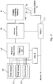
- a screening apparatus 1 for use in pre-screening patients prior to their undergoing an MRI scan comprises an elongate pole shaped housing 2, about 1.5 metres in length which is secured to a wall.
- the housing 2 contains an electronic circuit as will be described in relation to Figures 2 and 3 .
- the electronic circuit includes a number of sensors which detect the presence of magnetic objects in close proximity to the housing.
- the top of the housing 2 includes a warning device 4 in the form of a visible.
- the display 4 comprises a beacon with a set of three coloured lights within a transparent housing, allowing the display to emit red, amber or green light. It also contains a bar graph display to indicate the magnitude of the detected signal.
- a user operable input device in the form of a push button 5 is provided midway up the front of the housing 2 in a position where it can be conveniently operated by a person without having to stoop down. In use, as will be explained hereinafter, the display 4 provides a visible indication of the presence of a magnetic object 6 in proximity of the apparatus as detected by the sensors.
- the electronic circuit comprises first a main power supply unit PSU 1, which receives incoming power from a remote power supply (not shown but denoted by the phrase "power in”).
- a remote power supply (not shown but denoted by the phrase "power in”).
- This may comprise an AC-DC power pack that is located outside of the housing and connects through a power lead and plug to a suitable electrical outlet.
- the PSU1 converts the incoming power to positive and negative DC voltages of + 12v/-12v which are output to positive and negative supply lines in the housing.
- the sensors each comprise a sensitive flux gate magnetometer which is sensitive to changes in flux in a localised region of space in the vicinity of the sensor.
- the sensors are all sensitive over a common overlapping region of space. They are more sensitive to objects very close to the sensor within that space than they are to objects further away in that space.
- Other types of sensor could be provided, such as magneto-resistive sensors or Hall Effect sensors, or a galvanic coil sensor.
- Each sensor 10,11,12 outputs a respective measurement signal that is a measurement of the magnetic field incident upon the sensor 10,11,12.
- the measurement signal from each sensor is passed to a signal processing device forming readout electronics 13.
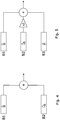
- two sensors could be provided but three are preferred as they can be configured to operate as a second order gradiometer.
- the configuration required for both the preferred embodiment with three sensors and the alternative with two sensors is illustrated in Figures 5 and 4 respectively, where n ⁇ is a unit vector defining the sensing direction of a sensor and B represents the magnetic field present at the sensor.
- the sensors With two sensors the sensors are arranged to sense in opposite directions and their outputs are summed as shown in Figure 4 .
- the sensors are arranged with B1 and B3 sensing in the same direction and B2 sensing in the opposite direction with a relative gain of two with respect to B1 and B3.
- the outputs are summed as shown in Figure 5 .
- the sensors could all sense in the same direction with B2 given a relative gain of minus-two.
- Output B 1 + B 3 ⁇ 2 B 2 ⁇ n ⁇ and if n ⁇ defines the x direction (extending radially away from the pole) an y defines a baseline extending vertically down through the sensors the output is therefore the second order derivative of the field component of B in the x direction with respect to the y direction, often expressed as ⁇ 2 B x / ⁇ y 2 , giving a much higher uniformity in the y direction and a much lower sensitivity to distant objects relative to the same object position at a distance compared with the two sensor arrangement.
- the apparatus will typically be fixed in position when in use for most of the time the sensors 10,11,12 will register a largely unchanging magnetic field due to the earth, and unchanging first and second order gradients. These constitute a large offset on the output of the sensor. This constant offset can be removed using a high pass filter in the readout electronics 13.
- the sensors will also likely measure regular changes in the magnetic field associated with the power supply for electrical equipment located near the sensors which will cause the output to vary at the supply frequency and its harmonics. This can also be filtered out using a low pass filter in the signal processing device.
- the filters 14 collectively constitute a band-pass filter 14 to perform these functions.
- the filtered output of the filters will therefore take a low value, ideally zero, in its steady state.
- the sensors and readout electronics receive power from PSU1.
- PSU1 power to the sensors 10,11,12 and the readout electronics 13, at least the filtering stage 14, is kept on at all times when the apparatus might be imminently be needed for pre-screening.
- the ambient magnetic field will be altered causing a change in the output of the sensor 10,11,12. That change will pass through the filter 14 and be amplified by an amplifier within the readout electronics.
- the signal size is compared with a preset threshold. Because the signal may be positive or negative, the threshold (set by a passing the signal through a threshold detector within the readout electronics) consists of a rectification stage followed by a comparator that has a circuit to provide a threshold voltage. Alternatively, separate comparators are used for positive and negative signals with the outputs combined to give a single alarm signal instead of a rectifier and a single comparator. An optional latch (not shown) may be provided which holds the value of the signal output from the comparator for a predetermined period- perhaps up to 1 second.
- the output of the comparator is arranged to have logic level zero for the state where the signal does not exceed the threshold, and level 'one' for the state when the signal has exceeded the threshold. Once an object has passed out of range of the sensors 10,11,12 the logic level returns to zero once the signal level has dropped below the threshold. In practice, it may be preferable that the alarm continues for an elapsed time defined by a reset delay and a latch such as a flip-flop that maintains the output at logic one until the switch/button 5 is pressed.
- the output of the latch is passed from the readout electronics to an input of the warning device, which comprises a display electronics circuit 15 that drives the display 4. It has been found to be beneficial, although not essential, that both a visual and audible alarm are provided.
- the rectified magnetic signal that feeds into the comparator may pass to the warning device to control a bar graph indicator. If the sensors have a digital output or if a digitizer is placed immediately after the sensors then the electronic functions described including the filters, rectifier, comparator, latches and delays may be done with a digital processor rather than in analog electronics.
- the warning device 15, 4 is powered from a second power supply PSU2.
- the power supply PSU2 has an input port 17 which receives a signal from the user operable device and depending on the state of the signal will power up or power down the display electronics. When powered down the display 4 will not issue a warning regardless of the value of the latched signal output from the readout electronics 13.
- PSU2 can be powered down without powering down PSU1, so that the warning device can be disabled without cutting power to the sensors 10,11,12 and filters 14.
- FIG. 3 of the drawings A modified electronic circuit which can be used is shown in Figure 3 of the drawings. Where parts are the same as those used in the circuit of Figure 2 the same reference numbers have been used for clarity, and the associated description above applies.
- the key difference is the omission of the second power supply unit PSU2, and the location of the switch 6 in the power supply line from PSU1 to the display electronics.
- the switch breaks the current flowing to the display electronics directly. This has the disadvantage that a break in the power supply line could cause unwanted magnetic fields to be generated unless care is taken during assembly, but does have the benefit of reducing the number and complexity of the components that are needed.
- the apparatus may be located at a convenient position in a pre-screening area.
- a mat 7 is positioned in front of the pole 2, which is in turn oriented so that the user input device faces the mat 7.
- the apparatus is then connected to a mains electricity supply (unless it contains its own battery power source). As soon as the filters have settled it is ready to use.
- a method of using the apparatus to pre-screen a patient is as follows with reference to Figure 6 of the accompanying drawings: Initially, before a person is screened a trained MRI person will take that person through a defined pre-screening procedure. First, the patient changes 100 into suitable clothing and removes any metal objects that they may be wearing such as jewellery, hair grips and so on. They are then asked to complete 200 a screening questionnaire which asks for details such as their medical history and whether they have any metal implants such as surgical pins. These preliminary stages may vary from hospital to hospital according to their local procedures so 100 and 200 are by way of example. Once this has been completed to the satisfaction of the trained MRI person, the MRI person will ensure that the warning device is enabled by pressing 300 the button 5 to switch on the screening apparatus.
- warning display 4 it otherwise may raise many false alarms as they pass close by and can make them feel that they are being constantly monitored. Furthermore the visual alarm can be distracting when the apparatus is not in use.
- the patient to be screened is invited to stand on the mat 7 in front of the pole with their arms by their side. They will then be asked to rotate 400 through a full circle (360 degrees) whilst remaining standing on the mat 7.
- the presence of ferromagnetic items on or in their body will trigger the warning device because the objects are moving and causing a change in the magnetic field within the overlapping detection zone. Additionally, as the person rotates the objects will trigger 500 the warning device because the magnetic field changes. If the person has a very small ferromagnetic object which is initially hidden from the device because it is positioned, say, on the opposite side of the persons body from the device, it will move closer to the sensors as the person rotates and will trigger the warning device as it moves.
- the person may then step off the mat. If no alarm was raised they can be cleared 700 to approach an MRI room. If an alarm is raised the person is asked 600 to identify any metal objects and remove them and a more detailed search of their body may be carried out to locate the ferromagnetic object that set off the warning device. The step of rotating the person in front of the apparatus is then repeated until no warning sound is issued. The patient is then deemed safe to proceed 700 to the MRI scanner room and the method of pre-screening ends 800.
- a modified step 400 is required if the patient is non-ambulatory.
- the patient would be screened in a non-magnetic portering chair, wheelchair or gurney (known as transfer equipment). Then the patient is pushed over the mat 7 in one direction and then rotated through one half turn (180 degrees) and pushed back past the apparatus over mat 7 so the other side of the patient is also scanned. This requires the MRI person to be free of ferromagnetic material so that neither the person or the transfer equipment cause an alarm.
- This method may be used to determine whether an object of unknown composition contains ferromagnetic material prior to being taken into an MRI room.
- Examples of items that could be tested are cylinders, patient monitoring equipment, tools, cleaning equipment, or anything where there is uncertainty as to whether it would be safe or a potential projectile effect hazard.
Landscapes
- Life Sciences & Earth Sciences (AREA)
- Health & Medical Sciences (AREA)
- Physics & Mathematics (AREA)
- Engineering & Computer Science (AREA)
- Remote Sensing (AREA)
- General Health & Medical Sciences (AREA)
- General Physics & Mathematics (AREA)
- Pathology (AREA)
- Chemical & Material Sciences (AREA)
- Biomedical Technology (AREA)
- Geology (AREA)
- Molecular Biology (AREA)
- Surgery (AREA)
- Animal Behavior & Ethology (AREA)
- Heart & Thoracic Surgery (AREA)
- Public Health (AREA)
- Veterinary Medicine (AREA)
- Electromagnetism (AREA)
- Biophysics (AREA)
- Environmental & Geological Engineering (AREA)
- Medical Informatics (AREA)
- General Life Sciences & Earth Sciences (AREA)
- Radiology & Medical Imaging (AREA)
- Geophysics (AREA)
- Nuclear Medicine, Radiotherapy & Molecular Imaging (AREA)
- Chemical Kinetics & Catalysis (AREA)
- Electrochemistry (AREA)
- Analytical Chemistry (AREA)
- Biochemistry (AREA)
- Immunology (AREA)
- Magnetic Resonance Imaging Apparatus (AREA)
- Emergency Alarm Devices (AREA)
- Geophysics And Detection Of Objects (AREA)
Priority Applications (1)
| Application Number | Priority Date | Filing Date | Title |
|---|---|---|---|
| EP18196557.5A EP3454092A1 (en) | 2011-06-29 | 2012-06-27 | Apparatus for detecting ferromagnetic objects and screening people and equipment |
Applications Claiming Priority (2)
| Application Number | Priority Date | Filing Date | Title |
|---|---|---|---|
| GBGB1111067.3A GB201111067D0 (en) | 2011-06-29 | 2011-06-29 | Apparatus for detecting ferromagnetic objects and screening people and equipment |
| PCT/GB2012/051500 WO2013001292A2 (en) | 2011-06-29 | 2012-06-27 | Apparatus for detecting ferromagnetic objects and screening people and equipment |
Related Child Applications (1)
| Application Number | Title | Priority Date | Filing Date |
|---|---|---|---|
| EP18196557.5A Division EP3454092A1 (en) | 2011-06-29 | 2012-06-27 | Apparatus for detecting ferromagnetic objects and screening people and equipment |
Publications (2)
| Publication Number | Publication Date |
|---|---|
| EP2725973A2 EP2725973A2 (en) | 2014-05-07 |
| EP2725973B1 true EP2725973B1 (en) | 2018-09-26 |
Family
ID=44485374
Family Applications (2)
| Application Number | Title | Priority Date | Filing Date |
|---|---|---|---|
| EP12761755.3A Active EP2725973B1 (en) | 2011-06-29 | 2012-06-27 | Apparatus for detecting ferromagnetic objects and screening people and equipment |
| EP18196557.5A Withdrawn EP3454092A1 (en) | 2011-06-29 | 2012-06-27 | Apparatus for detecting ferromagnetic objects and screening people and equipment |
Family Applications After (1)
| Application Number | Title | Priority Date | Filing Date |
|---|---|---|---|
| EP18196557.5A Withdrawn EP3454092A1 (en) | 2011-06-29 | 2012-06-27 | Apparatus for detecting ferromagnetic objects and screening people and equipment |
Country Status (8)
| Country | Link |
|---|---|
| US (2) | US9995713B2 (enExample) |
| EP (2) | EP2725973B1 (enExample) |
| JP (1) | JP2014522970A (enExample) |
| CN (1) | CN103747725A (enExample) |
| ES (1) | ES2699265T3 (enExample) |
| GB (1) | GB201111067D0 (enExample) |
| IN (1) | IN2014MN00149A (enExample) |
| WO (1) | WO2013001292A2 (enExample) |
Families Citing this family (16)
| Publication number | Priority date | Publication date | Assignee | Title |
|---|---|---|---|---|
| EP2807494A1 (en) * | 2012-03-22 | 2014-12-03 | TDK Corporation | Movable coil scanner systems and methods |
| US20130307533A1 (en) | 2012-05-18 | 2013-11-21 | Metrasens Limited | Security system and method of detecting contraband items |
| GB201219097D0 (en) | 2012-10-24 | 2012-12-05 | Metrasens Ltd | Apparatus for detecting ferromagnetic objects at a protected doorway assembly |
| JP6152008B2 (ja) * | 2013-08-01 | 2017-06-21 | 株式会社ディード | 磁性体検知機 |
| CN105658139B (zh) | 2013-10-21 | 2019-06-04 | 皇家飞利浦有限公司 | 用于磁共振成像的安全监测 |
| CN103955001A (zh) * | 2014-05-14 | 2014-07-30 | 三峡大学 | 一种隐形耳机探测装置及探测方法 |
| CN110045423A (zh) | 2014-12-18 | 2019-07-23 | 梅特拉森斯有限公司 | 安全系统及检测违禁品的方法 |
| GB201602652D0 (en) * | 2016-02-15 | 2016-03-30 | Metrasens Ltd | Improvements to magnetic detectors |
| US9860685B1 (en) * | 2016-06-29 | 2018-01-02 | Cisco Technology, Inc. | Presence indicator signal |
| GB2556926A (en) | 2016-11-25 | 2018-06-13 | Metrasens Ltd | Monitoring system for a detection system |
| GB2558210A (en) * | 2016-12-21 | 2018-07-11 | Metrasens Ltd | System and apparatus for ferromagnetically screening prone patients |
| US11287495B2 (en) * | 2017-05-22 | 2022-03-29 | Advanced Bionics Ag | Methods and apparatus for use with cochlear implants having magnet apparatus with magnetic material particles |
| DE102017209373A1 (de) * | 2017-06-02 | 2018-12-06 | Bruker Biospin Mri Gmbh | Schnelles Verfahren zur Bestimmung der Position eines ferromagnetischen Partikels oder eines Bündels ferromagnetischer Partikel mit MRI-Systemen |
| CN108303746B (zh) * | 2018-01-17 | 2021-05-18 | 上海联影医疗科技股份有限公司 | 金属物检测的方法、存储介质和磁共振成像系统 |
| US11966003B2 (en) | 2019-03-28 | 2024-04-23 | Zkteco Usa Llc | System and method for a security post |
| WO2025227224A1 (en) * | 2024-04-30 | 2025-11-06 | Xtract One Detection Ltd. | System and method for object detection and classification using time-domain electromagnetic transmission |
Citations (1)
| Publication number | Priority date | Publication date | Assignee | Title |
|---|---|---|---|---|
| US20070052411A1 (en) * | 2003-01-17 | 2007-03-08 | Mednovus, Inc. | Screening method and apparatus |
Family Cites Families (23)
| Publication number | Priority date | Publication date | Assignee | Title |
|---|---|---|---|---|
| US4024468A (en) * | 1975-06-18 | 1977-05-17 | White's Electronics, Inc. | Induction balance metal detector with inverse discrimination |
| US4249128A (en) * | 1978-02-06 | 1981-02-03 | White's Electronics, Inc. | Wide pulse gated metal detector with improved noise rejection |
| US4334191A (en) * | 1979-01-29 | 1982-06-08 | Garrett Electronics | Metal detector circuit having momentary disabled output |
| US4488115A (en) | 1980-11-12 | 1984-12-11 | Garrett Electronics | Low battery voltage indicator circuit for a metal detector |
| ZA876706B (en) * | 1986-09-08 | 1988-05-25 | Candy Bruce Halcro | Method of discrimination detection using two frequencies |
| US5039981A (en) * | 1989-10-11 | 1991-08-13 | Rodriguez Joe S | Electromagnetic security detectors |
| US5148151A (en) * | 1990-06-20 | 1992-09-15 | Garrett Electronics, Inc. | Metal detector having target characterization and search classification |
| US5959451A (en) | 1997-08-18 | 1999-09-28 | Torfino Enterprises, Inc. | Metal detector with vibrating tactile indicator mounted within a compact housing |
| GB0124887D0 (en) * | 2001-10-17 | 2001-12-05 | Qinetiq Ltd | Metal detection apparatus |
| US8014847B2 (en) * | 2001-12-13 | 2011-09-06 | Musc Foundation For Research Development | Systems and methods for detecting deception by measuring brain activity |
| US7489128B2 (en) * | 2002-03-11 | 2009-02-10 | Kopp Keith A | MRI protector |
| WO2003091753A1 (en) * | 2002-04-25 | 2003-11-06 | National Research Council Of Canada | Detection of ferromagnetic objects approaching a magnet |
| US7296683B1 (en) | 2002-05-22 | 2007-11-20 | Vallelonga Sr Kenneth M | Ferrous metal detector with alarm |
| GB2395276B (en) | 2002-11-12 | 2006-03-08 | Qinetiq Ltd | Ferromagnetic object detector |
| US7315166B2 (en) | 2003-01-17 | 2008-01-01 | Mednovus, Inc. | Magnetic resonance imaging screening method and apparatus |
| US7295107B2 (en) * | 2004-12-30 | 2007-11-13 | Mednovus, Inc. | Ferromagnetic detection pillar |
| US20060145691A1 (en) * | 2004-12-30 | 2006-07-06 | Mednovus, Inc. | Ferromagnetic detection pillar and variable aperture portal |
| US7408461B2 (en) * | 2005-01-11 | 2008-08-05 | Controlled Capture Systems, Llc | Metal detection system and method |
| WO2008028487A1 (en) * | 2006-09-07 | 2008-03-13 | Alert Metalguard Aps | A system and a method for electronically monitoring goods |
| US7893690B2 (en) * | 2007-07-19 | 2011-02-22 | Carnes Company, Inc. | Balancing circuit for a metal detector |
| GB0905298D0 (en) * | 2009-03-27 | 2009-05-13 | Qinetiq Ltd | Apparatus and method for ferromagnetic object detector |
| CN101584583B (zh) * | 2009-06-16 | 2010-10-27 | 中国人民解放军第四军医大学 | 便携式金属异物快速排查装置 |
| US20130307533A1 (en) * | 2012-05-18 | 2013-11-21 | Metrasens Limited | Security system and method of detecting contraband items |
-
2011
- 2011-06-29 GB GBGB1111067.3A patent/GB201111067D0/en not_active Ceased
-
2012
- 2012-06-27 EP EP12761755.3A patent/EP2725973B1/en active Active
- 2012-06-27 IN IN149MUN2014 patent/IN2014MN00149A/en unknown
- 2012-06-27 US US14/129,877 patent/US9995713B2/en active Active
- 2012-06-27 EP EP18196557.5A patent/EP3454092A1/en not_active Withdrawn
- 2012-06-27 WO PCT/GB2012/051500 patent/WO2013001292A2/en not_active Ceased
- 2012-06-27 CN CN201280040318.1A patent/CN103747725A/zh active Pending
- 2012-06-27 JP JP2014517934A patent/JP2014522970A/ja active Pending
- 2012-06-27 ES ES12761755T patent/ES2699265T3/es active Active
-
2018
- 2018-05-01 US US15/968,413 patent/US20180246063A1/en not_active Abandoned
Patent Citations (1)
| Publication number | Priority date | Publication date | Assignee | Title |
|---|---|---|---|---|
| US20070052411A1 (en) * | 2003-01-17 | 2007-03-08 | Mednovus, Inc. | Screening method and apparatus |
Also Published As
| Publication number | Publication date |
|---|---|
| JP2014522970A (ja) | 2014-09-08 |
| WO2013001292A2 (en) | 2013-01-03 |
| ES2699265T3 (es) | 2019-02-08 |
| GB201111067D0 (en) | 2011-08-10 |
| IN2014MN00149A (enExample) | 2015-06-19 |
| US9995713B2 (en) | 2018-06-12 |
| US20140232382A1 (en) | 2014-08-21 |
| EP2725973A2 (en) | 2014-05-07 |
| CN103747725A (zh) | 2014-04-23 |
| US20180246063A1 (en) | 2018-08-30 |
| WO2013001292A3 (en) | 2013-07-04 |
| EP3454092A1 (en) | 2019-03-13 |
Similar Documents
| Publication | Publication Date | Title |
|---|---|---|
| EP2725973B1 (en) | Apparatus for detecting ferromagnetic objects and screening people and equipment | |
| US11551538B2 (en) | Waste receptacle | |
| US10815053B2 (en) | Waste receptacle | |
| JP4477503B2 (ja) | 強磁性体検出器 | |
| US7106056B2 (en) | Security screening method and apparatus | |
| EP2146224A2 (en) | Magnetic Body Detector | |
| JP2025069271A (ja) | 強磁性検出器および脅威分析 | |
| GB2558210A (en) | System and apparatus for ferromagnetically screening prone patients | |
| JP6259981B2 (ja) | 磁性体検知機 |
Legal Events
| Date | Code | Title | Description |
|---|---|---|---|
| PUAI | Public reference made under article 153(3) epc to a published international application that has entered the european phase |
Free format text: ORIGINAL CODE: 0009012 |
|
| 17P | Request for examination filed |
Effective date: 20140121 |
|
| AK | Designated contracting states |
Kind code of ref document: A2 Designated state(s): AL AT BE BG CH CY CZ DE DK EE ES FI FR GB GR HR HU IE IS IT LI LT LU LV MC MK MT NL NO PL PT RO RS SE SI SK SM TR |
|
| DAX | Request for extension of the european patent (deleted) | ||
| STAA | Information on the status of an ep patent application or granted ep patent |
Free format text: STATUS: EXAMINATION IS IN PROGRESS |
|
| 17Q | First examination report despatched |
Effective date: 20171011 |
|
| GRAP | Despatch of communication of intention to grant a patent |
Free format text: ORIGINAL CODE: EPIDOSNIGR1 |
|
| STAA | Information on the status of an ep patent application or granted ep patent |
Free format text: STATUS: GRANT OF PATENT IS INTENDED |
|
| INTG | Intention to grant announced |
Effective date: 20180606 |
|
| GRAJ | Information related to disapproval of communication of intention to grant by the applicant or resumption of examination proceedings by the epo deleted |
Free format text: ORIGINAL CODE: EPIDOSDIGR1 |
|
| STAA | Information on the status of an ep patent application or granted ep patent |
Free format text: STATUS: EXAMINATION IS IN PROGRESS |
|
| GRAR | Information related to intention to grant a patent recorded |
Free format text: ORIGINAL CODE: EPIDOSNIGR71 |
|
| GRAS | Grant fee paid |
Free format text: ORIGINAL CODE: EPIDOSNIGR3 |
|
| STAA | Information on the status of an ep patent application or granted ep patent |
Free format text: STATUS: GRANT OF PATENT IS INTENDED |
|
| GRAA | (expected) grant |
Free format text: ORIGINAL CODE: 0009210 |
|
| STAA | Information on the status of an ep patent application or granted ep patent |
Free format text: STATUS: THE PATENT HAS BEEN GRANTED |
|
| INTC | Intention to grant announced (deleted) | ||
| INTG | Intention to grant announced |
Effective date: 20180816 |
|
| AK | Designated contracting states |
Kind code of ref document: B1 Designated state(s): AL AT BE BG CH CY CZ DE DK EE ES FI FR GB GR HR HU IE IS IT LI LT LU LV MC MK MT NL NO PL PT RO RS SE SI SK SM TR |
|
| REG | Reference to a national code |
Ref country code: GB Ref legal event code: FG4D |
|
| REG | Reference to a national code |
Ref country code: CH Ref legal event code: EP |
|
| REG | Reference to a national code |
Ref country code: AT Ref legal event code: REF Ref document number: 1045052 Country of ref document: AT Kind code of ref document: T Effective date: 20181015 |
|
| REG | Reference to a national code |
Ref country code: IE Ref legal event code: FG4D |
|
| REG | Reference to a national code |
Ref country code: DE Ref legal event code: R096 Ref document number: 602012051530 Country of ref document: DE |
|
| REG | Reference to a national code |
Ref country code: NL Ref legal event code: FP |
|
| PG25 | Lapsed in a contracting state [announced via postgrant information from national office to epo] |
Ref country code: FI Free format text: LAPSE BECAUSE OF FAILURE TO SUBMIT A TRANSLATION OF THE DESCRIPTION OR TO PAY THE FEE WITHIN THE PRESCRIBED TIME-LIMIT Effective date: 20180926 Ref country code: RS Free format text: LAPSE BECAUSE OF FAILURE TO SUBMIT A TRANSLATION OF THE DESCRIPTION OR TO PAY THE FEE WITHIN THE PRESCRIBED TIME-LIMIT Effective date: 20180926 Ref country code: NO Free format text: LAPSE BECAUSE OF FAILURE TO SUBMIT A TRANSLATION OF THE DESCRIPTION OR TO PAY THE FEE WITHIN THE PRESCRIBED TIME-LIMIT Effective date: 20181226 Ref country code: GR Free format text: LAPSE BECAUSE OF FAILURE TO SUBMIT A TRANSLATION OF THE DESCRIPTION OR TO PAY THE FEE WITHIN THE PRESCRIBED TIME-LIMIT Effective date: 20181227 Ref country code: SE Free format text: LAPSE BECAUSE OF FAILURE TO SUBMIT A TRANSLATION OF THE DESCRIPTION OR TO PAY THE FEE WITHIN THE PRESCRIBED TIME-LIMIT Effective date: 20180926 Ref country code: BG Free format text: LAPSE BECAUSE OF FAILURE TO SUBMIT A TRANSLATION OF THE DESCRIPTION OR TO PAY THE FEE WITHIN THE PRESCRIBED TIME-LIMIT Effective date: 20181226 Ref country code: LT Free format text: LAPSE BECAUSE OF FAILURE TO SUBMIT A TRANSLATION OF THE DESCRIPTION OR TO PAY THE FEE WITHIN THE PRESCRIBED TIME-LIMIT Effective date: 20180926 |
|
| REG | Reference to a national code |
Ref country code: ES Ref legal event code: FG2A Ref document number: 2699265 Country of ref document: ES Kind code of ref document: T3 Effective date: 20190208 |
|
| REG | Reference to a national code |
Ref country code: LT Ref legal event code: MG4D |
|
| PG25 | Lapsed in a contracting state [announced via postgrant information from national office to epo] |
Ref country code: AL Free format text: LAPSE BECAUSE OF FAILURE TO SUBMIT A TRANSLATION OF THE DESCRIPTION OR TO PAY THE FEE WITHIN THE PRESCRIBED TIME-LIMIT Effective date: 20180926 Ref country code: LV Free format text: LAPSE BECAUSE OF FAILURE TO SUBMIT A TRANSLATION OF THE DESCRIPTION OR TO PAY THE FEE WITHIN THE PRESCRIBED TIME-LIMIT Effective date: 20180926 Ref country code: HR Free format text: LAPSE BECAUSE OF FAILURE TO SUBMIT A TRANSLATION OF THE DESCRIPTION OR TO PAY THE FEE WITHIN THE PRESCRIBED TIME-LIMIT Effective date: 20180926 |
|
| REG | Reference to a national code |
Ref country code: AT Ref legal event code: MK05 Ref document number: 1045052 Country of ref document: AT Kind code of ref document: T Effective date: 20180926 |
|
| PG25 | Lapsed in a contracting state [announced via postgrant information from national office to epo] |
Ref country code: IS Free format text: LAPSE BECAUSE OF FAILURE TO SUBMIT A TRANSLATION OF THE DESCRIPTION OR TO PAY THE FEE WITHIN THE PRESCRIBED TIME-LIMIT Effective date: 20190126 Ref country code: PL Free format text: LAPSE BECAUSE OF FAILURE TO SUBMIT A TRANSLATION OF THE DESCRIPTION OR TO PAY THE FEE WITHIN THE PRESCRIBED TIME-LIMIT Effective date: 20180926 Ref country code: CZ Free format text: LAPSE BECAUSE OF FAILURE TO SUBMIT A TRANSLATION OF THE DESCRIPTION OR TO PAY THE FEE WITHIN THE PRESCRIBED TIME-LIMIT Effective date: 20180926 Ref country code: RO Free format text: LAPSE BECAUSE OF FAILURE TO SUBMIT A TRANSLATION OF THE DESCRIPTION OR TO PAY THE FEE WITHIN THE PRESCRIBED TIME-LIMIT Effective date: 20180926 Ref country code: EE Free format text: LAPSE BECAUSE OF FAILURE TO SUBMIT A TRANSLATION OF THE DESCRIPTION OR TO PAY THE FEE WITHIN THE PRESCRIBED TIME-LIMIT Effective date: 20180926 Ref country code: AT Free format text: LAPSE BECAUSE OF FAILURE TO SUBMIT A TRANSLATION OF THE DESCRIPTION OR TO PAY THE FEE WITHIN THE PRESCRIBED TIME-LIMIT Effective date: 20180926 |
|
| PG25 | Lapsed in a contracting state [announced via postgrant information from national office to epo] |
Ref country code: SM Free format text: LAPSE BECAUSE OF FAILURE TO SUBMIT A TRANSLATION OF THE DESCRIPTION OR TO PAY THE FEE WITHIN THE PRESCRIBED TIME-LIMIT Effective date: 20180926 Ref country code: SK Free format text: LAPSE BECAUSE OF FAILURE TO SUBMIT A TRANSLATION OF THE DESCRIPTION OR TO PAY THE FEE WITHIN THE PRESCRIBED TIME-LIMIT Effective date: 20180926 Ref country code: PT Free format text: LAPSE BECAUSE OF FAILURE TO SUBMIT A TRANSLATION OF THE DESCRIPTION OR TO PAY THE FEE WITHIN THE PRESCRIBED TIME-LIMIT Effective date: 20190126 |
|
| REG | Reference to a national code |
Ref country code: DE Ref legal event code: R097 Ref document number: 602012051530 Country of ref document: DE |
|
| PG25 | Lapsed in a contracting state [announced via postgrant information from national office to epo] |
Ref country code: DK Free format text: LAPSE BECAUSE OF FAILURE TO SUBMIT A TRANSLATION OF THE DESCRIPTION OR TO PAY THE FEE WITHIN THE PRESCRIBED TIME-LIMIT Effective date: 20180926 |
|
| PGFP | Annual fee paid to national office [announced via postgrant information from national office to epo] |
Ref country code: IE Payment date: 20190509 Year of fee payment: 8 Ref country code: DE Payment date: 20190619 Year of fee payment: 8 |
|
| PLBE | No opposition filed within time limit |
Free format text: ORIGINAL CODE: 0009261 |
|
| STAA | Information on the status of an ep patent application or granted ep patent |
Free format text: STATUS: NO OPPOSITION FILED WITHIN TIME LIMIT |
|
| PGFP | Annual fee paid to national office [announced via postgrant information from national office to epo] |
Ref country code: FR Payment date: 20190619 Year of fee payment: 8 |
|
| 26N | No opposition filed |
Effective date: 20190627 |
|
| PG25 | Lapsed in a contracting state [announced via postgrant information from national office to epo] |
Ref country code: SI Free format text: LAPSE BECAUSE OF FAILURE TO SUBMIT A TRANSLATION OF THE DESCRIPTION OR TO PAY THE FEE WITHIN THE PRESCRIBED TIME-LIMIT Effective date: 20180926 |
|
| PG25 | Lapsed in a contracting state [announced via postgrant information from national office to epo] |
Ref country code: MC Free format text: LAPSE BECAUSE OF FAILURE TO SUBMIT A TRANSLATION OF THE DESCRIPTION OR TO PAY THE FEE WITHIN THE PRESCRIBED TIME-LIMIT Effective date: 20180926 |
|
| REG | Reference to a national code |
Ref country code: CH Ref legal event code: PL |
|
| REG | Reference to a national code |
Ref country code: BE Ref legal event code: MM Effective date: 20190630 |
|
| PG25 | Lapsed in a contracting state [announced via postgrant information from national office to epo] |
Ref country code: TR Free format text: LAPSE BECAUSE OF FAILURE TO SUBMIT A TRANSLATION OF THE DESCRIPTION OR TO PAY THE FEE WITHIN THE PRESCRIBED TIME-LIMIT Effective date: 20180926 |
|
| PG25 | Lapsed in a contracting state [announced via postgrant information from national office to epo] |
Ref country code: IE Free format text: LAPSE BECAUSE OF NON-PAYMENT OF DUE FEES Effective date: 20190627 |
|
| PG25 | Lapsed in a contracting state [announced via postgrant information from national office to epo] |
Ref country code: BE Free format text: LAPSE BECAUSE OF NON-PAYMENT OF DUE FEES Effective date: 20190630 Ref country code: LI Free format text: LAPSE BECAUSE OF NON-PAYMENT OF DUE FEES Effective date: 20190630 Ref country code: LU Free format text: LAPSE BECAUSE OF NON-PAYMENT OF DUE FEES Effective date: 20190627 Ref country code: CH Free format text: LAPSE BECAUSE OF NON-PAYMENT OF DUE FEES Effective date: 20190630 |
|
| REG | Reference to a national code |
Ref country code: DE Ref legal event code: R119 Ref document number: 602012051530 Country of ref document: DE |
|
| REG | Reference to a national code |
Ref country code: NL Ref legal event code: MM Effective date: 20200701 |
|
| PG25 | Lapsed in a contracting state [announced via postgrant information from national office to epo] |
Ref country code: NL Free format text: LAPSE BECAUSE OF NON-PAYMENT OF DUE FEES Effective date: 20200701 Ref country code: FR Free format text: LAPSE BECAUSE OF NON-PAYMENT OF DUE FEES Effective date: 20200630 |
|
| PG25 | Lapsed in a contracting state [announced via postgrant information from national office to epo] |
Ref country code: CY Free format text: LAPSE BECAUSE OF FAILURE TO SUBMIT A TRANSLATION OF THE DESCRIPTION OR TO PAY THE FEE WITHIN THE PRESCRIBED TIME-LIMIT Effective date: 20180926 Ref country code: DE Free format text: LAPSE BECAUSE OF NON-PAYMENT OF DUE FEES Effective date: 20210101 |
|
| PG25 | Lapsed in a contracting state [announced via postgrant information from national office to epo] |
Ref country code: MT Free format text: LAPSE BECAUSE OF FAILURE TO SUBMIT A TRANSLATION OF THE DESCRIPTION OR TO PAY THE FEE WITHIN THE PRESCRIBED TIME-LIMIT Effective date: 20180926 Ref country code: HU Free format text: LAPSE BECAUSE OF FAILURE TO SUBMIT A TRANSLATION OF THE DESCRIPTION OR TO PAY THE FEE WITHIN THE PRESCRIBED TIME-LIMIT; INVALID AB INITIO Effective date: 20120627 |
|
| REG | Reference to a national code |
Ref country code: ES Ref legal event code: FD2A Effective date: 20211105 |
|
| PG25 | Lapsed in a contracting state [announced via postgrant information from national office to epo] |
Ref country code: ES Free format text: LAPSE BECAUSE OF NON-PAYMENT OF DUE FEES Effective date: 20200628 |
|
| PG25 | Lapsed in a contracting state [announced via postgrant information from national office to epo] |
Ref country code: MK Free format text: LAPSE BECAUSE OF FAILURE TO SUBMIT A TRANSLATION OF THE DESCRIPTION OR TO PAY THE FEE WITHIN THE PRESCRIBED TIME-LIMIT Effective date: 20180926 |
|
| P01 | Opt-out of the competence of the unified patent court (upc) registered |
Effective date: 20230428 |
|
| PGFP | Annual fee paid to national office [announced via postgrant information from national office to epo] |
Ref country code: GB Payment date: 20250618 Year of fee payment: 14 |
|
| PGFP | Annual fee paid to national office [announced via postgrant information from national office to epo] |
Ref country code: IT Payment date: 20250619 Year of fee payment: 14 |