EP2725594A1 - Capacitance element housing unit - Google Patents
Capacitance element housing unit Download PDFInfo
- Publication number
- EP2725594A1 EP2725594A1 EP11868840.7A EP11868840A EP2725594A1 EP 2725594 A1 EP2725594 A1 EP 2725594A1 EP 11868840 A EP11868840 A EP 11868840A EP 2725594 A1 EP2725594 A1 EP 2725594A1
- Authority
- EP
- European Patent Office
- Prior art keywords
- capacitance element
- capacitance
- housing unit
- power
- case
- Prior art date
- Legal status (The legal status is an assumption and is not a legal conclusion. Google has not performed a legal analysis and makes no representation as to the accuracy of the status listed.)
- Withdrawn
Links
- 238000001816 cooling Methods 0.000 claims abstract description 11
- 238000006243 chemical reaction Methods 0.000 claims description 10
- 230000000694 effects Effects 0.000 abstract description 2
- 238000004873 anchoring Methods 0.000 abstract 1
- 238000001914 filtration Methods 0.000 description 21
- 238000009499 grossing Methods 0.000 description 19
- 238000003860 storage Methods 0.000 description 9
- 230000001629 suppression Effects 0.000 description 6
- HBBGRARXTFLTSG-UHFFFAOYSA-N Lithium ion Chemical compound [Li+] HBBGRARXTFLTSG-UHFFFAOYSA-N 0.000 description 3
- 239000004020 conductor Substances 0.000 description 3
- 238000009413 insulation Methods 0.000 description 3
- 229910001416 lithium ion Inorganic materials 0.000 description 3
- 229910052751 metal Inorganic materials 0.000 description 3
- 239000002184 metal Substances 0.000 description 3
- 239000002826 coolant Substances 0.000 description 2
- 239000000110 cooling liquid Substances 0.000 description 2
- 238000005336 cracking Methods 0.000 description 2
- 239000003575 carbonaceous material Substances 0.000 description 1
- 239000000498 cooling water Substances 0.000 description 1
- 238000010586 diagram Methods 0.000 description 1
- 238000009826 distribution Methods 0.000 description 1
- 239000003792 electrolyte Substances 0.000 description 1
- 239000000463 material Substances 0.000 description 1
- 238000000034 method Methods 0.000 description 1
- 239000007774 positive electrode material Substances 0.000 description 1
- 238000004382 potting Methods 0.000 description 1
- 230000001172 regenerating effect Effects 0.000 description 1
- 239000011347 resin Substances 0.000 description 1
- 229920005989 resin Polymers 0.000 description 1
Images


Classifications
-
- H—ELECTRICITY
- H01—ELECTRIC ELEMENTS
- H01G—CAPACITORS; CAPACITORS, RECTIFIERS, DETECTORS, SWITCHING DEVICES, LIGHT-SENSITIVE OR TEMPERATURE-SENSITIVE DEVICES OF THE ELECTROLYTIC TYPE
- H01G2/00—Details of capacitors not covered by a single one of groups H01G4/00-H01G11/00
- H01G2/08—Cooling arrangements; Heating arrangements; Ventilating arrangements
-
- H—ELECTRICITY
- H01—ELECTRIC ELEMENTS
- H01G—CAPACITORS; CAPACITORS, RECTIFIERS, DETECTORS, SWITCHING DEVICES, LIGHT-SENSITIVE OR TEMPERATURE-SENSITIVE DEVICES OF THE ELECTROLYTIC TYPE
- H01G11/00—Hybrid capacitors, i.e. capacitors having different positive and negative electrodes; Electric double-layer [EDL] capacitors; Processes for the manufacture thereof or of parts thereof
- H01G11/08—Structural combinations, e.g. assembly or connection, of hybrid or EDL capacitors with other electric components, at least one hybrid or EDL capacitor being the main component
-
- H—ELECTRICITY
- H01—ELECTRIC ELEMENTS
- H01G—CAPACITORS; CAPACITORS, RECTIFIERS, DETECTORS, SWITCHING DEVICES, LIGHT-SENSITIVE OR TEMPERATURE-SENSITIVE DEVICES OF THE ELECTROLYTIC TYPE
- H01G11/00—Hybrid capacitors, i.e. capacitors having different positive and negative electrodes; Electric double-layer [EDL] capacitors; Processes for the manufacture thereof or of parts thereof
- H01G11/14—Arrangements or processes for adjusting or protecting hybrid or EDL capacitors
- H01G11/18—Arrangements or processes for adjusting or protecting hybrid or EDL capacitors against thermal overloads, e.g. heating, cooling or ventilating
-
- H—ELECTRICITY
- H02—GENERATION; CONVERSION OR DISTRIBUTION OF ELECTRIC POWER
- H02M—APPARATUS FOR CONVERSION BETWEEN AC AND AC, BETWEEN AC AND DC, OR BETWEEN DC AND DC, AND FOR USE WITH MAINS OR SIMILAR POWER SUPPLY SYSTEMS; CONVERSION OF DC OR AC INPUT POWER INTO SURGE OUTPUT POWER; CONTROL OR REGULATION THEREOF
- H02M7/00—Conversion of AC power input into DC power output; Conversion of DC power input into AC power output
- H02M7/003—Constructional details, e.g. physical layout, assembly, wiring or busbar connections
-
- H—ELECTRICITY
- H05—ELECTRIC TECHNIQUES NOT OTHERWISE PROVIDED FOR
- H05K—PRINTED CIRCUITS; CASINGS OR CONSTRUCTIONAL DETAILS OF ELECTRIC APPARATUS; MANUFACTURE OF ASSEMBLAGES OF ELECTRICAL COMPONENTS
- H05K7/00—Constructional details common to different types of electric apparatus
- H05K7/14—Mounting supporting structure in casing or on frame or rack
- H05K7/1422—Printed circuit boards receptacles, e.g. stacked structures, electronic circuit modules or box like frames
- H05K7/1427—Housings
- H05K7/1432—Housings specially adapted for power drive units or power converters
- H05K7/14329—Housings specially adapted for power drive units or power converters specially adapted for the configuration of power bus bars
-
- H—ELECTRICITY
- H05—ELECTRIC TECHNIQUES NOT OTHERWISE PROVIDED FOR
- H05K—PRINTED CIRCUITS; CASINGS OR CONSTRUCTIONAL DETAILS OF ELECTRIC APPARATUS; MANUFACTURE OF ASSEMBLAGES OF ELECTRICAL COMPONENTS
- H05K7/00—Constructional details common to different types of electric apparatus
- H05K7/20—Modifications to facilitate cooling, ventilating, or heating
- H05K7/2039—Modifications to facilitate cooling, ventilating, or heating characterised by the heat transfer by conduction from the heat generating element to a dissipating body
-
- H—ELECTRICITY
- H05—ELECTRIC TECHNIQUES NOT OTHERWISE PROVIDED FOR
- H05K—PRINTED CIRCUITS; CASINGS OR CONSTRUCTIONAL DETAILS OF ELECTRIC APPARATUS; MANUFACTURE OF ASSEMBLAGES OF ELECTRICAL COMPONENTS
- H05K7/00—Constructional details common to different types of electric apparatus
- H05K7/20—Modifications to facilitate cooling, ventilating, or heating
- H05K7/2089—Modifications to facilitate cooling, ventilating, or heating for power electronics, e.g. for inverters for controlling motor
- H05K7/20927—Liquid coolant without phase change
-
- Y—GENERAL TAGGING OF NEW TECHNOLOGICAL DEVELOPMENTS; GENERAL TAGGING OF CROSS-SECTIONAL TECHNOLOGIES SPANNING OVER SEVERAL SECTIONS OF THE IPC; TECHNICAL SUBJECTS COVERED BY FORMER USPC CROSS-REFERENCE ART COLLECTIONS [XRACs] AND DIGESTS
- Y02—TECHNOLOGIES OR APPLICATIONS FOR MITIGATION OR ADAPTATION AGAINST CLIMATE CHANGE
- Y02E—REDUCTION OF GREENHOUSE GAS [GHG] EMISSIONS, RELATED TO ENERGY GENERATION, TRANSMISSION OR DISTRIBUTION
- Y02E60/00—Enabling technologies; Technologies with a potential or indirect contribution to GHG emissions mitigation
- Y02E60/13—Energy storage using capacitors
-
- Y—GENERAL TAGGING OF NEW TECHNOLOGICAL DEVELOPMENTS; GENERAL TAGGING OF CROSS-SECTIONAL TECHNOLOGIES SPANNING OVER SEVERAL SECTIONS OF THE IPC; TECHNICAL SUBJECTS COVERED BY FORMER USPC CROSS-REFERENCE ART COLLECTIONS [XRACs] AND DIGESTS
- Y02—TECHNOLOGIES OR APPLICATIONS FOR MITIGATION OR ADAPTATION AGAINST CLIMATE CHANGE
- Y02T—CLIMATE CHANGE MITIGATION TECHNOLOGIES RELATED TO TRANSPORTATION
- Y02T10/00—Road transport of goods or passengers
- Y02T10/60—Other road transportation technologies with climate change mitigation effect
- Y02T10/70—Energy storage systems for electromobility, e.g. batteries
Definitions
- the present invention relates to a capacitance element housing unit.
- a hybrid vehicle is provided with a power converter which converts output electric power from a power storage device and supplies the converted electric power to a motor generator.
- the power converter is provided with a smoothing capacitance element which is connected to an input side of an inverter, and a filtering capacitance element which is connected to an input side of a DC-to-DC converter. It should be noted here that because the heatproof temperature of the smoothing capacitance element and that of the filtering capacitance element may be different, heat transfer between these capacitance elements should be suppressed when the smoothing capacitance element and the filtering capacitance element are enclosed in a single common package.
- Patent Document 1 discloses a power conversion unit which includes a DC-to-DC converter which receives DC power from a DC power supply and converts the received DC power to a different voltage level to output the DC power; an inverter which receives the DC power from the DC-to-DC converter and converts the received DC power to AC power to output the AC power; a first capacitance element provided on the input side of the DC-to-DC converter; and a second capacitance element provided on the input side of the inverter.
- a DC-to-DC converter which receives DC power from a DC power supply and converts the received DC power to a different voltage level to output the DC power
- an inverter which receives the DC power from the DC-to-DC converter and converts the received DC power to AC power to output the AC power
- a first capacitance element provided on the input side of the DC-to-DC converter
- a second capacitance element provided on the input side of the inverter.
- first capacitance element and the second capacitance element are enclosed in a common package, and that, in order to suppress heat transfer between the first capacitance element and the second capacitance element, a slit is provided between the first capacitance element and the second capacitance element.
- Patent Document 1 JP 2009-44920 A
- An obj ect of the present invention is to provide a capacitance element housing unit with which heat transfer suppression effect between capacitance elements can be enhanced more suitably.
- a capacitance element housing unit comprises a common package which encloses a plurality of capacitance elements and includes a slit portion provided at a location between the plurality of capacitance elements where temperature becomes high; a case comprising a cooling portion which cools an element enclosed inside; and a fixing portion which fixes, in the slit portion, the common package to the case.
- the fixing portion is provided at a location corresponding to a center between the capacitance elements which are adjacent to the slit portions.
- a capacitance element housing unit comprises a busbar connected to the plurality of capacitance elements; and the busbar is connected to the fixing portion.
- a capacitance element housing unit the case encloses a first power conversion circuit and a second power conversion circuit, and the plurality of capacitance elements comprises: a first capacitance element connected to the first power conversion circuit; and a second capacitance element connected to the second power conversion circuit.
- a slit portion is provided at a location between two or more capacitance elements where the temperature becomes high; and a common package is fixed, in the slit portion, to a case which includes a cooling portion.
- the heat from the two or more capacitance elements is allowed to transfer via the common package and the fixingportion. Therefore, it becomes possible to enhance heat transfer suppression effect more suitably.
- FIG. 1 shows a configuration of a power converter system 8 including a capacitance element housing unit 10.
- the power converter system 8 is provided with a power storage device 12, a motor generator 22, a power converter 23, and a controller 24.
- the power converter 23 is provided with a capacitance element housing unit 10, a filtering capacitance element 14, a DC-to-DC converter 16, a smoothing capacitance element 18, and an inverter 20.
- the power converter system 8 is assumed to be mounted on a hybrid vehicle.
- the power storage device 12 is a battery which supplies electric power to the motor generator 22.
- the power storage device 12 is also a chargeable and dischargeable DC power supply, which is, for example, a lithium ion secondary battery which includes a negative electrode made from a carbon material, electrolyte in which lithium ions can transfer, and a positive electrode active material in relation to which the lithium ions can be reversibly inserted into and removed from.
- the filtering capacitance element 14 is provided on the input side of the DC-to-DC converter 16.
- the filtering capacitance element 14 is connected in parallel to the power storage device 12.
- the filtering capacitance element 14 has a function to suppress electric power fluctuation of the power storage device 12 which occurs during switching operation of a switching element included in the DC-to-DC converter 16.
- the DC-to-DC converter 16 is a power converter circuit which boosts output electric power from the power storage device 12 and supplies the boosted electric power to the inverter 20 side.
- the DC-to-DC converter 16 also steps down the DC power supplied as regenerated power from the inverter 20 side and supplies the stepped down power to the power storage device 12 as charging electric power.
- the smoothing capacitance element 18 is a capacitance element which is provided on the inverter 20 side.
- the smoothing capacitance element 18 has a function to suppress electric power fluctuation between a positive electrode bus 1 and a negative electrode bus 2.
- the positive electrode bus 1 is a power wire which connects terminals on the positive electrode sides of the DC-to-DC converter 16 and the inverter 20.
- the negative electrode bus 2 is a power wire which connects terminals on the negative electrode sides of the DC-to-DC converter 16 and the inverter 20.
- the heatproof temperature T 1 of the smoothing capacitance element 18 is different from the heatproof temperature T 2 of the filtering capacitance element 14. For example, the heatproof temperature T 2 of the filtering capacitance element 14 is higher than the heatproof temperature T 1 of the smoothing capacitance element 18.
- the inverter 20 is a power converter circuit which converts DC power output from the DC-to-DC converter 16 to AC power and supplies the converted power to the motor generator 22 during power-applied running of a hybrid vehicle.
- the inverter 20 also converts AC power which is regenerated energy generated by the motor generator 22 and supplies the converted power to the DC-to-DC converter 16 during regenerating running of a hybrid vehicle.
- the motor generator 22 is a three phase AC rotary electric machine (load circuit) which is configured to include a U-phase coil, a V-phase coil, and a W-phase coil.
- the motor generator 22 is connected with wheels of a hybrid vehicle via a power distribution mechanism (not shown).
- the controller 24 has a function to control the whole power converter 23.
- the controller 24 includes, for example, switching control of a switching element of the inverter 20 and the DC-to-DC converter 16.
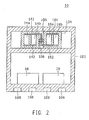
- FIG. 2 is a cross-sectional view of the capacitance element housing unit 10.
- the capacitance element housing unit 10 is provided with a case 102, a common package 104, and a fixing portion 106.
- the case 102 internally encloses the common package 104 and the fixing portion 106.
- the common package 104 is fixed to an internal wall of the case 102 by the fixing portion 106.
- the case 102 internally encloses the DC-to-DC converter 16 and the inverter 20.
- the case 102 is made from a conductive material such as metal having heat conductivity higher than that of the common package 104.
- the case 102 functions as a shield between the outside and the internally enclosed DC-to-DC converter 16 and the inverter 20.
- the case 102 has a cooling flow channel 108 through which coolant such as cooling liquid (cooling water) flows.
- the cooling flow channel 108 is a cooling portion which cools the case 102 by the cooling liquid which internally flows. This can achieve cooling of the DC-to-DC converter 16 and the inverter 20 enclosed inside the case 102.
- FIG. 3 is a perspective view of the common package 104 and the fixing portion 106.
- the common package 104 unitedly encloses and packages the filtering capacitance element 14 and the smoothing capacitance element 18.
- the filtering capacitance element 14 has two capacitance elements 14a, 14b.
- the smoothing capacitance element 18 includes two capacitance elements 18a, 18b. Although each of the filtering capacitance element 14 and the smoothing capacitance element 18 is assumed to have two capacitance elements in the description below, the number of the capacitance elements can be other than two.
- the capacitance elements 14a, 14b and the capacitance elements 18a, 18b are enclosed to be spaced from each other.
- Each of the capacitance elements 14a, 14b and the capacitance elements 18a, 18b is sealed by a potting resin material surrounding these elements.
- the capacitance elements 14a, 14b and the capacitance elements 18a, 18b are enclosed in a single package, heat is easily transferred between these capacitance elements.
- capacitance elements are required to sufficiently achieve performance within the heatproof temperature.
- the heatproof temperatures of the two or more capacitance elements are different, because heat is transferred from a capacitance element having a higher heatproof temperature to a capacitance element having a lower heatproof temperature, the capacitance element having the higher heatproof temperature should be used in accordance with the capacitance element having the lower heatproof temperature. In such a case, the performance of the capacitance element having the higher heatproof temperature cannot be sufficiently achieved.
- a slit portion 105 is formed for suppressing the heat transfer between the capacitance element 14b and the capacitance element 18a which have different heatproof temperatures.
- the slit portion 105 is located between the capacitance element 14b and the capacitance element 18a which have different heatproof temperatures where the temperature becomes high in the common package 104.
- This slit portion 105 can suppress the heat transfer between the capacitance element 14b and the capacitance element 18a.
- the heat transfer from the capacitance element 14b to the capacitance element 18a can be suppressed.
- the two filtering capacitance elements 14a, 14b forming the filtering capacitance element 14 are connected between the positive electrodes and between the negative electrodes respectively by a busbar 141 and a busbar 142.
- the busbar 141 connects between the positive electrodes of the capacitance elements 14a, 14b, while the busbar 142 connects between the negative electrodes of the capacitance elements 14a, 14b.
- An end portion of the busbar 141 is further connected to a conductive portion 106a of the fixing portion 106.
- the two capacitance elements 18a, 18b forming the smoothing capacitance element 18 are connected between the positive electrodes and between the negative electrodes respectively by a busbar 181 and a busbar 182.
- the busbar 181 connects between the positive electrodes of the capacitance elements 18a, 18b
- the busbar 182 connects between the negative electrodes of the capacitance elements 18a, 18b.
- An end portion of the busbar 182 is further connected to a conductive portion 106c of the fixing portion 106.
- the busbars 141, 142, 181, and 182 are made from a conductive material such as metal having high heat conductivity.
- the fixing portion 106 is a fixing member located in the slit portion 105 to fix the common package 104 to an inner wall of the case 102 at the center in the height direction (arrow h) of the capacitance element 14b and the capacitance element 18a which are adjacent to the slit portion 105.
- the fixing portion 106 is provided with the conductive portions 106a, 106c which are conductively connected to the case 102, and an insulation portion 106b sandwiched between the conductive portions 106a, 106c to insulate between the conductive portions 106a, 106c.
- the conductive portions 106a, 106c are made from a conductive material such as metal having high heat conductivity.
- the heatproof temperature T 1 of the smoothing capacitance element 18 is different from the heatproof temperature T 2 of the filtering capacitance element 14.
- the heatproof temperature T 2 of the filtering capacitance element 14 is higher than the heatproof temperature T 1 of the smoothing capacitance element 18.
- the capacitance element housing unit 10 shown in FIGs. 1 to 3 it becomes possible to allow the heat of the capacitance element 14b of the filtering capacitance element 14 and the heat of the capacitance element 18a of the smoothing capacitance element 18 to transfer to the case 102 side via the fixing portion 106 having a high coefficient of heat conduction.
- the case 102 because coolant flows in the cooling flow channel 108 of the case 102 in order to cool the DC-to-DC converter 16 and the inverter 20, the case 102 itself is also cooled. In this way, as the heat of the capacitance element 14b and the capacitance element 18a is allowed to transfer, these capacitance elements are cooled.
- the heat transfer suppression effect between the capacitance element 14b and the capacitance element 18a can be enhanced. Further, because the fixing portion 106 is provided at the center portion where the temperature of the heat generated from the capacitance element 14b and the capacitance element 18a becomes the highest, the heat transfer can be suppressed more suitably.
- an end portion of the busbar 141 which is connected to the positive electrodes of the two capacitance elements 14a, 14b forming the filtering capacitance element 14 is connected to the conductive portion 106a of the fixing portion 106. Because this allows the heat generated from the capacitance elements 14a, 14b to transfer to the case 102 side via the busbar 141 and the conductive portion 106a, the capacitance elements 14a, 14b themselves can be cooled.
- an end portion of the busbar 182 which is connected to the negative electrodes of the two capacitance elements 18a, 18b forming the smoothing capacitance element 18 is connected to the conductive portion 106c of the fixing portion 106. Because this allows the heat generated from the capacitance elements 18a, 18b to transfer to the case 102 side via the busbar 182 and the conductive portion 106c, the capacitance elements 18a, 18b themselves can be cooled.
- busbar 141 and the busbar 182 are described as being connected to the fixing portion 106, the busbar 142 and the busbar 181 may be connected to each other. Alternatively, by increasing the number of insulation portions, all of the busbars may be connected to the case 102.
- 1 positive electrode bus, 2 negative electrode bus, 8 power converter system 10 capacitance element housing unit, 12 power storage device, 14 filtering capacitance element, 14a, 14b capacitance elements, 16 converter, 18 smoothing capacitance element, 18a, 18b capacitance elements, 20 inverter, 22 motor generator, 23 power converter, 24 controller, 102 case, 104 common package, 105 slit portion, 106 fixing portion, 106a, 106c conductive portions, 106b insulation portion, 108 cooling flow channel, and 141, 142, 181, 182 busbars.
Landscapes
- Engineering & Computer Science (AREA)
- Power Engineering (AREA)
- Microelectronics & Electronic Packaging (AREA)
- Physics & Mathematics (AREA)
- Thermal Sciences (AREA)
- Inverter Devices (AREA)
- Dc-Dc Converters (AREA)
- Fixed Capacitors And Capacitor Manufacturing Machines (AREA)
- Electric Propulsion And Braking For Vehicles (AREA)
Abstract
Description
- The present invention relates to a capacitance element housing unit.
- A hybrid vehicle is provided with a power converter which converts output electric power from a power storage device and supplies the converted electric power to a motor generator. The power converter is provided with a smoothing capacitance element which is connected to an input side of an inverter, and a filtering capacitance element which is connected to an input side of a DC-to-DC converter. It should be noted here that because the heatproof temperature of the smoothing capacitance element and that of the filtering capacitance element may be different, heat transfer between these capacitance elements should be suppressed when the smoothing capacitance element and the filtering capacitance element are enclosed in a single common package.
- As a technique relating to the present invention, for example,
Patent Document 1 discloses a power conversion unit which includes a DC-to-DC converter which receives DC power from a DC power supply and converts the received DC power to a different voltage level to output the DC power; an inverter which receives the DC power from the DC-to-DC converter and converts the received DC power to AC power to output the AC power; a first capacitance element provided on the input side of the DC-to-DC converter; and a second capacitance element provided on the input side of the inverter. It is disclosed that the first capacitance element and the second capacitance element are enclosed in a common package, and that, in order to suppress heat transfer between the first capacitance element and the second capacitance element, a slit is provided between the first capacitance element and the second capacitance element. - Patent Document 1:
JP 2009-44920 A - Although it is possible to suppress heat transfer between the smoothing capacitance element and the filtering capacitance element according to
Patent Document 1, it is necessary to provide a wide slit in order to enhance heat transfer suppression effect. However, a wide slit causes a risk of lowering the strength of the common package. - An obj ect of the present invention is to provide a capacitance element housing unit with which heat transfer suppression effect between capacitance elements can be enhanced more suitably.
- A capacitance element housing unit according to the present invention comprises a common package which encloses a plurality of capacitance elements and includes a slit portion provided at a location between the plurality of capacitance elements where temperature becomes high; a case comprising a cooling portion which cools an element enclosed inside; and a fixing portion which fixes, in the slit portion, the common package to the case.
- Further, it is preferable that, in a capacitance element housing unit according to the present invention, the fixing portion is provided at a location corresponding to a center between the capacitance elements which are adjacent to the slit portions.
- Further, it is preferable that a capacitance element housing unit according to the present invention comprises a busbar connected to the plurality of capacitance elements; and the busbar is connected to the fixing portion.
- Further, it is preferable that, in a capacitance element housing unit according to the present invention, the case encloses a first power conversion circuit and a second power conversion circuit, and the plurality of capacitance elements comprises: a first capacitance element connected to the first power conversion circuit; and a second capacitance element connected to the second power conversion circuit.
- According to the above configuration, a slit portion is provided at a location between two or more capacitance elements where the temperature becomes high; and a common package is fixed, in the slit portion, to a case which includes a cooling portion. In this way, the heat from the two or more capacitance elements is allowed to transfer via the common package and the fixingportion. Therefore, it becomes possible to enhance heat transfer suppression effect more suitably.
-
-
FIG. 1 shows a configuration of a power conversion system including a capacitance element housing unit in an embodiment according to the present invention. -
FIG. 2 shows a cross-sectional view of a capacitance element housing unit in an embodiment according to the present invention. -
FIG. 3 shows a perspective diagram of a common package and a fixing portion in an embodiment according to the present invention. - In the description below, throughout the drawings, the same reference numerals are assigned to similar elements, and duplicate description is omitted. Further, in the description below, previously cited reference numerals are indicated where appropriate.
-
FIG. 1 shows a configuration of apower converter system 8 including a capacitanceelement housing unit 10. Thepower converter system 8 is provided with apower storage device 12, amotor generator 22, apower converter 23, and acontroller 24. Thepower converter 23 is provided with a capacitanceelement housing unit 10, afiltering capacitance element 14, a DC-to-DC converter 16, asmoothing capacitance element 18, and aninverter 20. In the following description, thepower converter system 8 is assumed to be mounted on a hybrid vehicle. - The
power storage device 12 is a battery which supplies electric power to themotor generator 22. Thepower storage device 12 is also a chargeable and dischargeable DC power supply, which is, for example, a lithium ion secondary battery which includes a negative electrode made from a carbon material, electrolyte in which lithium ions can transfer, and a positive electrode active material in relation to which the lithium ions can be reversibly inserted into and removed from. - The
filtering capacitance element 14 is provided on the input side of the DC-to-DC converter 16. Thefiltering capacitance element 14 is connected in parallel to thepower storage device 12. Thefiltering capacitance element 14 has a function to suppress electric power fluctuation of thepower storage device 12 which occurs during switching operation of a switching element included in the DC-to-DC converter 16. - The DC-to-
DC converter 16 is a power converter circuit which boosts output electric power from thepower storage device 12 and supplies the boosted electric power to theinverter 20 side. The DC-to-DC converter 16 also steps down the DC power supplied as regenerated power from theinverter 20 side and supplies the stepped down power to thepower storage device 12 as charging electric power. - The
smoothing capacitance element 18 is a capacitance element which is provided on theinverter 20 side. Thesmoothing capacitance element 18 has a function to suppress electric power fluctuation between apositive electrode bus 1 and anegative electrode bus 2. Thepositive electrode bus 1 is a power wire which connects terminals on the positive electrode sides of the DC-to-DC converter 16 and theinverter 20. Thenegative electrode bus 2 is a power wire which connects terminals on the negative electrode sides of the DC-to-DC converter 16 and theinverter 20. The heatproof temperature T1 of thesmoothing capacitance element 18 is different from the heatproof temperature T2 of thefiltering capacitance element 14. For example, the heatproof temperature T2 of thefiltering capacitance element 14 is higher than the heatproof temperature T1 of thesmoothing capacitance element 18. - The
inverter 20 is a power converter circuit which converts DC power output from the DC-to-DC converter 16 to AC power and supplies the converted power to themotor generator 22 during power-applied running of a hybrid vehicle. Theinverter 20 also converts AC power which is regenerated energy generated by themotor generator 22 and supplies the converted power to the DC-to-DC converter 16 during regenerating running of a hybrid vehicle. - The
motor generator 22 is a three phase AC rotary electric machine (load circuit) which is configured to include a U-phase coil, a V-phase coil, and a W-phase coil. Themotor generator 22 is connected with wheels of a hybrid vehicle via a power distribution mechanism (not shown). - The
controller 24 has a function to control thewhole power converter 23. Thecontroller 24 includes, for example, switching control of a switching element of theinverter 20 and the DC-to-DC converter 16. - The capacitance
element housing unit 10 is described next.FIG. 2 is a cross-sectional view of the capacitanceelement housing unit 10. - The capacitance
element housing unit 10 is provided with acase 102, acommon package 104, and afixing portion 106. Thecase 102 internally encloses thecommon package 104 and thefixing portion 106. Thecommon package 104 is fixed to an internal wall of thecase 102 by thefixing portion 106. - The
case 102 internally encloses the DC-to-DC converter 16 and theinverter 20. Thecase 102 is made from a conductive material such as metal having heat conductivity higher than that of thecommon package 104. Thecase 102 functions as a shield between the outside and the internally enclosed DC-to-DC converter 16 and theinverter 20. Thecase 102 has acooling flow channel 108 through which coolant such as cooling liquid (cooling water) flows. Thecooling flow channel 108 is a cooling portion which cools thecase 102 by the cooling liquid which internally flows. This can achieve cooling of the DC-to-DC converter 16 and theinverter 20 enclosed inside thecase 102. -
FIG. 3 is a perspective view of thecommon package 104 and thefixing portion 106. Thecommon package 104 unitedly encloses and packages thefiltering capacitance element 14 and the smoothingcapacitance element 18. Thefiltering capacitance element 14 has twocapacitance elements capacitance element 18 includes twocapacitance elements filtering capacitance element 14 and the smoothingcapacitance element 18 is assumed to have two capacitance elements in the description below, the number of the capacitance elements can be other than two. - As shown in
FIG. 3 , in thecommon package 104, thecapacitance elements capacitance elements capacitance elements capacitance elements - It should be noted that when the
capacitance elements capacitance elements - Regarding this issue, in the
common package 104, as shown inFIG. 3 , aslit portion 105 is formed for suppressing the heat transfer between thecapacitance element 14b and thecapacitance element 18a which have different heatproof temperatures. Theslit portion 105 is located between thecapacitance element 14b and thecapacitance element 18a which have different heatproof temperatures where the temperature becomes high in thecommon package 104. Thisslit portion 105 can suppress the heat transfer between thecapacitance element 14b and thecapacitance element 18a. Thus, because it becomes possible to thermally separate thecapacitance element 14b having the higher heatproof temperature and thecapacitance element 18a having the lower heatproof temperature, the heat transfer from thecapacitance element 14b to thecapacitance element 18a can be suppressed. - Further, the two filtering
capacitance elements filtering capacitance element 14 are connected between the positive electrodes and between the negative electrodes respectively by abusbar 141 and abusbar 142. Specifically, thebusbar 141 connects between the positive electrodes of thecapacitance elements busbar 142 connects between the negative electrodes of thecapacitance elements busbar 141 is further connected to aconductive portion 106a of the fixingportion 106. - Further, the two
capacitance elements capacitance element 18 are connected between the positive electrodes and between the negative electrodes respectively by abusbar 181 and abusbar 182. Specifically, thebusbar 181 connects between the positive electrodes of thecapacitance elements busbar 182 connects between the negative electrodes of thecapacitance elements busbar 182 is further connected to aconductive portion 106c of the fixingportion 106. Thebusbars - The fixing
portion 106 is a fixing member located in theslit portion 105 to fix thecommon package 104 to an inner wall of thecase 102 at the center in the height direction (arrow h) of thecapacitance element 14b and thecapacitance element 18a which are adjacent to theslit portion 105. The fixingportion 106 is provided with theconductive portions case 102, and an insulation portion 106b sandwiched between theconductive portions conductive portions conductive portions - Subsequently, advantages of the capacitance
element housing unit 10 having the above structure are described below by referring toFIGs. 1 to 3 . - In general, the heatproof temperature T1 of the smoothing
capacitance element 18 is different from the heatproof temperature T2 of thefiltering capacitance element 14. For example, the heatproof temperature T2 of thefiltering capacitance element 14 is higher than the heatproof temperature T1 of the smoothingcapacitance element 18. Thus, by forming theslit portion 105 with thecommon package 104, the transfer of heat from thefiltering capacitance element 14 to the smoothingcapacitance element 18 is suppressed. In order to achieve higher heat transfer suppression effect, it is necessary to broaden the slit width of theslit portion 105. However, if the slit width is broadened excessively, there is a risk of cracking in thecommon package 104 which could occur due to vibration or the like during running or other occasions of the hybrid vehicle. Therefore, it is necessary to enhance the heat suppression effect while suppressing cracking in thecommon package 104 due to vibration or the like during running of the hybrid vehicle or other occasions. This is an object to be achieved by the present invention. - According to the capacitance
element housing unit 10 shown inFIGs. 1 to 3 , it becomes possible to allow the heat of thecapacitance element 14b of thefiltering capacitance element 14 and the heat of thecapacitance element 18a of the smoothingcapacitance element 18 to transfer to thecase 102 side via the fixingportion 106 having a high coefficient of heat conduction. It should be noted here that, as described above, because coolant flows in thecooling flow channel 108 of thecase 102 in order to cool the DC-to-DC converter 16 and theinverter 20, thecase 102 itself is also cooled. In this way, as the heat of thecapacitance element 14b and thecapacitance element 18a is allowed to transfer, these capacitance elements are cooled. Therefore, the heat transfer suppression effect between thecapacitance element 14b and thecapacitance element 18a can be enhanced. Further, because the fixingportion 106 is provided at the center portion where the temperature of the heat generated from thecapacitance element 14b and thecapacitance element 18a becomes the highest, the heat transfer can be suppressed more suitably. - Further, according to the capacitance
element housing unit 10, an end portion of thebusbar 141 which is connected to the positive electrodes of the twocapacitance elements filtering capacitance element 14 is connected to theconductive portion 106a of the fixingportion 106. Because this allows the heat generated from thecapacitance elements case 102 side via thebusbar 141 and theconductive portion 106a, thecapacitance elements busbar 182 which is connected to the negative electrodes of the twocapacitance elements capacitance element 18 is connected to theconductive portion 106c of the fixingportion 106. Because this allows the heat generated from thecapacitance elements case 102 side via thebusbar 182 and theconductive portion 106c, thecapacitance elements - It should be noted that, although, in accordance with the above capacitance
element housing unit 10, thebusbar 141 and thebusbar 182 are described as being connected to the fixingportion 106, thebusbar 142 and thebusbar 181 may be connected to each other. Alternatively, by increasing the number of insulation portions, all of the busbars may be connected to thecase 102. - 1 positive electrode bus, 2 negative electrode bus, 8 power converter system, 10 capacitance element housing unit, 12 power storage device, 14 filtering capacitance element, 14a, 14b capacitance elements, 16 converter, 18 smoothing capacitance element, 18a, 18b capacitance elements, 20 inverter, 22 motor generator, 23 power converter, 24 controller, 102 case, 104 common package, 105 slit portion, 106 fixing portion, 106a, 106c conductive portions, 106b insulation portion, 108 cooling flow channel, and 141, 142, 181, 182 busbars.
Claims (4)
- A capacitance element housing unit comprising:a common package which encloses a plurality of capacitance elements and includes a slit portion provided at a location between the plurality of capacitance elements where temperature becomes high;a case comprising a cooling portion which cools an element enclosed inside; anda fixing portion which fixes, in the slit portion, the common package to the case.
- The capacitance element housing unit according to claim 1, wherein
the fixing portion is provided at a location corresponding to a center between the capacitance elements which are adjacent to the slit portions. - The capacitance element housing unit according to claim 1 or 2, wherein
the capacitance element housing unit further comprises a busbar connected to the plurality of capacitance elements; and
the busbar is connected to the fixing portion. - The capacitance element housing unit according to any one of claims 1 to 3, wherein
the case encloses a first power conversion circuit and a second power conversion circuit, and
the plurality of capacitance elements comprises:a first capacitance element connected to the first power conversion circuit; anda second capacitance element connected to the second power conversion circuit.
Applications Claiming Priority (1)
| Application Number | Priority Date | Filing Date | Title |
|---|---|---|---|
| PCT/JP2011/064707 WO2013001595A1 (en) | 2011-06-27 | 2011-06-27 | Capacitance element housing unit |
Publications (2)
| Publication Number | Publication Date |
|---|---|
| EP2725594A1 true EP2725594A1 (en) | 2014-04-30 |
| EP2725594A4 EP2725594A4 (en) | 2015-03-11 |
Family
ID=47423541
Family Applications (1)
| Application Number | Title | Priority Date | Filing Date |
|---|---|---|---|
| EP11868840.7A Withdrawn EP2725594A4 (en) | 2011-06-27 | 2011-06-27 | CAPACITIVE ELEMENT HOUSING UNIT |
Country Status (5)
| Country | Link |
|---|---|
| US (1) | US20140146588A1 (en) |
| EP (1) | EP2725594A4 (en) |
| JP (1) | JP5821956B2 (en) |
| CN (1) | CN103608880A (en) |
| WO (1) | WO2013001595A1 (en) |
Families Citing this family (6)
| Publication number | Priority date | Publication date | Assignee | Title |
|---|---|---|---|---|
| JP6379353B2 (en) * | 2014-08-04 | 2018-08-29 | パナソニックIpマネジメント株式会社 | DC-DC converter |
| JP6679400B2 (en) * | 2016-04-27 | 2020-04-15 | ニチコン株式会社 | Caseless film capacitor |
| JP2018078247A (en) * | 2016-11-11 | 2018-05-17 | トヨタ自動車株式会社 | Capacitor module |
| JP6890750B6 (en) * | 2017-07-10 | 2021-07-28 | 株式会社アイシン | Smoothing capacitor unit |
| JP7065595B2 (en) * | 2017-12-13 | 2022-05-12 | 株式会社Soken | Film capacitor module |
| JP7234845B2 (en) * | 2019-07-26 | 2023-03-08 | 株式会社デンソー | capacitor unit |
Family Cites Families (12)
| Publication number | Priority date | Publication date | Assignee | Title |
|---|---|---|---|---|
| US3018427A (en) * | 1958-08-13 | 1962-01-23 | Westinghouse Electric Corp | Power capacitor units |
| US4714979A (en) * | 1986-12-16 | 1987-12-22 | Advance Transformer Company | Protected potted metallized film capacitor |
| FI99267C (en) * | 1992-12-29 | 1998-02-10 | Nokia Kondensaattorit Oy | Capacitor with internal protection |
| JP2001326131A (en) * | 2000-05-18 | 2001-11-22 | Matsushita Electric Ind Co Ltd | Capacitors |
| JP4090287B2 (en) * | 2002-06-21 | 2008-05-28 | 日産ディーゼル工業株式会社 | Capacitor storage container |
| WO2007032273A1 (en) * | 2005-09-13 | 2007-03-22 | Nec Corporation | Electric device module and production method therefor |
| JP2007220794A (en) * | 2006-02-15 | 2007-08-30 | Toyota Motor Corp | Capacitor device |
| US7471498B2 (en) * | 2006-03-15 | 2008-12-30 | Electronic Concepts, Inc. | Wound capacitor having a thermal disconnect at a hot spot |
| JP4702311B2 (en) * | 2007-03-19 | 2011-06-15 | トヨタ自動車株式会社 | Electrical unit with a capacitor |
| JP5109528B2 (en) * | 2007-08-10 | 2012-12-26 | トヨタ自動車株式会社 | Power conversion unit |
| JP2009194080A (en) * | 2008-02-13 | 2009-08-27 | Daikin Ind Ltd | Capacitor module |
| JP5048705B2 (en) * | 2009-03-26 | 2012-10-17 | 本田技研工業株式会社 | Power converter for vehicle |
-
2011
- 2011-06-27 WO PCT/JP2011/064707 patent/WO2013001595A1/en not_active Ceased
- 2011-06-27 EP EP11868840.7A patent/EP2725594A4/en not_active Withdrawn
- 2011-06-27 US US14/129,172 patent/US20140146588A1/en not_active Abandoned
- 2011-06-27 JP JP2013522383A patent/JP5821956B2/en active Active
- 2011-06-27 CN CN201180071740.9A patent/CN103608880A/en active Pending
Also Published As
| Publication number | Publication date |
|---|---|
| JP5821956B2 (en) | 2015-11-24 |
| JPWO2013001595A1 (en) | 2015-02-23 |
| WO2013001595A1 (en) | 2013-01-03 |
| EP2725594A4 (en) | 2015-03-11 |
| US20140146588A1 (en) | 2014-05-29 |
| CN103608880A (en) | 2014-02-26 |
Similar Documents
| Publication | Publication Date | Title |
|---|---|---|
| US12009133B2 (en) | Temperature regulation of an inductor assembly | |
| KR101850413B1 (en) | Electric motor vehicle | |
| JP5769386B2 (en) | Electric propulsion device and electric vehicle equipped with the same | |
| CN104081648B (en) | Power-converting device | |
| KR102532313B1 (en) | Hybrid power control unit for vehicle | |
| EP2725594A1 (en) | Capacitance element housing unit | |
| EP3182483A1 (en) | Battery pack | |
| JP5815063B2 (en) | Power converter | |
| KR102326063B1 (en) | Film capacitor module of inverter for vehicle | |
| US9437860B2 (en) | Traction battery assembly having snap-in bus bar module | |
| US20180301983A1 (en) | Power converter | |
| JP2012033419A (en) | Power supply device, vehicle using the same, battery cell, and method of manufacturing the battery cell | |
| US20190115848A1 (en) | Power converter | |
| US20180262122A1 (en) | Power converter | |
| WO2014024451A1 (en) | Power source device, electric vehicle provided with same, and electricity storage device | |
| CN208754008U (en) | Liquid-cooled charging system for electric automobile | |
| WO2012057169A1 (en) | Power-supply device, vehicle using same, battery cell, and battery-cell manufacturing method | |
| US10230289B2 (en) | Three-phase inverter for motor | |
| JP5633475B2 (en) | Power converter | |
| JP2015154527A (en) | Power converter | |
| JP2018060684A (en) | Power supply | |
| JP2014150215A (en) | Cooling device and motor control device including the same | |
| JP2021034349A (en) | Rechargeable battery and in-wheel electric system | |
| US10355586B2 (en) | Power converter | |
| US20230268114A1 (en) | Pickup apparatus using multi pickup coil for wireless charging of electric vehicle and industrial equipment |
Legal Events
| Date | Code | Title | Description |
|---|---|---|---|
| PUAI | Public reference made under article 153(3) epc to a published international application that has entered the european phase |
Free format text: ORIGINAL CODE: 0009012 |
|
| 17P | Request for examination filed |
Effective date: 20140124 |
|
| AK | Designated contracting states |
Kind code of ref document: A1 Designated state(s): AL AT BE BG CH CY CZ DE DK EE ES FI FR GB GR HR HU IE IS IT LI LT LU LV MC MK MT NL NO PL PT RO RS SE SI SK SM TR |
|
| DAX | Request for extension of the european patent (deleted) | ||
| A4 | Supplementary search report drawn up and despatched |
Effective date: 20150205 |
|
| RIC1 | Information provided on ipc code assigned before grant |
Ipc: H01G 11/18 20130101ALI20150130BHEP Ipc: H01G 2/08 20060101AFI20150130BHEP Ipc: H02M 7/00 20060101ALI20150130BHEP Ipc: H05K 7/14 20060101ALI20150130BHEP Ipc: H01G 11/08 20130101ALI20150130BHEP |
|
| STAA | Information on the status of an ep patent application or granted ep patent |
Free format text: STATUS: THE APPLICATION HAS BEEN WITHDRAWN |
|
| 18W | Application withdrawn |
Effective date: 20151230 |