EP2724701B1 - Support de tête destiné à des tables d'opération - Google Patents
Support de tête destiné à des tables d'opération Download PDFInfo
- Publication number
- EP2724701B1 EP2724701B1 EP20120190367 EP12190367A EP2724701B1 EP 2724701 B1 EP2724701 B1 EP 2724701B1 EP 20120190367 EP20120190367 EP 20120190367 EP 12190367 A EP12190367 A EP 12190367A EP 2724701 B1 EP2724701 B1 EP 2724701B1
- Authority
- EP
- European Patent Office
- Prior art keywords
- head support
- head
- holding
- holding element
- holding elements
- Prior art date
- Legal status (The legal status is an assumption and is not a legal conclusion. Google has not performed a legal analysis and makes no representation as to the accuracy of the status listed.)
- Active
Links
- 210000003128 head Anatomy 0.000 claims description 105
- 230000008878 coupling Effects 0.000 claims description 34
- 238000010168 coupling process Methods 0.000 claims description 34
- 238000005859 coupling reaction Methods 0.000 claims description 34
- 210000001061 forehead Anatomy 0.000 claims description 3
- 239000013013 elastic material Substances 0.000 claims description 2
- 208000027418 Wounds and injury Diseases 0.000 description 5
- 208000014674 injury Diseases 0.000 description 5
- 238000001356 surgical procedure Methods 0.000 description 5
- 230000006378 damage Effects 0.000 description 4
- 230000001360 synchronised effect Effects 0.000 description 3
- 230000000295 complement effect Effects 0.000 description 2
- 230000000694 effects Effects 0.000 description 2
- 208000011092 Hand injury Diseases 0.000 description 1
- 230000001419 dependent effect Effects 0.000 description 1
- 230000005489 elastic deformation Effects 0.000 description 1
- 210000000245 forearm Anatomy 0.000 description 1
- 238000001746 injection moulding Methods 0.000 description 1
- 238000004519 manufacturing process Methods 0.000 description 1
- 239000000463 material Substances 0.000 description 1
- 229920003023 plastic Polymers 0.000 description 1
- 239000004033 plastic Substances 0.000 description 1
Images


Classifications
-
- A—HUMAN NECESSITIES
- A61—MEDICAL OR VETERINARY SCIENCE; HYGIENE
- A61G—TRANSPORT, PERSONAL CONVEYANCES, OR ACCOMMODATION SPECIALLY ADAPTED FOR PATIENTS OR DISABLED PERSONS; OPERATING TABLES OR CHAIRS; CHAIRS FOR DENTISTRY; FUNERAL DEVICES
- A61G13/00—Operating tables; Auxiliary appliances therefor
- A61G13/10—Parts, details or accessories
- A61G13/12—Rests specially adapted therefor; Arrangements of patient-supporting surfaces
-
- A—HUMAN NECESSITIES
- A61—MEDICAL OR VETERINARY SCIENCE; HYGIENE
- A61F—FILTERS IMPLANTABLE INTO BLOOD VESSELS; PROSTHESES; DEVICES PROVIDING PATENCY TO, OR PREVENTING COLLAPSING OF, TUBULAR STRUCTURES OF THE BODY, e.g. STENTS; ORTHOPAEDIC, NURSING OR CONTRACEPTIVE DEVICES; FOMENTATION; TREATMENT OR PROTECTION OF EYES OR EARS; BANDAGES, DRESSINGS OR ABSORBENT PADS; FIRST-AID KITS
- A61F5/00—Orthopaedic methods or devices for non-surgical treatment of bones or joints; Nursing devices; Anti-rape devices
- A61F5/37—Restraining devices for the body or for body parts, e.g. slings; Restraining shirts
- A61F5/3707—Restraining devices for the body or for body parts, e.g. slings; Restraining shirts for the head
-
- A—HUMAN NECESSITIES
- A61—MEDICAL OR VETERINARY SCIENCE; HYGIENE
- A61G—TRANSPORT, PERSONAL CONVEYANCES, OR ACCOMMODATION SPECIALLY ADAPTED FOR PATIENTS OR DISABLED PERSONS; OPERATING TABLES OR CHAIRS; CHAIRS FOR DENTISTRY; FUNERAL DEVICES
- A61G13/00—Operating tables; Auxiliary appliances therefor
- A61G13/10—Parts, details or accessories
- A61G13/12—Rests specially adapted therefor; Arrangements of patient-supporting surfaces
- A61G13/1205—Rests specially adapted therefor; Arrangements of patient-supporting surfaces for specific parts of the body
- A61G13/121—Head or neck
Definitions
- the invention relates to a head support for operating tables comprising a first holding element rotatably mounted about a first axis of rotation for surrounding a first side of a patient's head receivable in a receiving area of the head support and a second holding element rotatably mounted about a second axis of rotation for surrounding a second side of the patient's head.
- the first holding element and the second holding element are coupled to each other in a coupling area by means of at least one coupling element such that when one of the holding elements is rotated, the coupling element also rotates the other holding element.
- a head support is attached to the operating table by means of which a secure fixing of the head during the surgery shall take place to guarantee thus a secure performance of the surgery being as low risk as possible for the patient.
- a head support comprising two holding elements, each laterally surrounding the patient's head which are coupled to each other in a coupling area.
- an arcuate oblong hole is provided in one of the two holding elements, in which a pin connected to the other holding element is guided.
- the other holding element is also rotated along and is thus also opened or closed.
- One problematic aspect of this coupling is that the coupling via the oblong hole and the pin is relatively unstable and can easily get caught and a synchronous opening and closing is not ensured.
- Another problematic aspect is that the patient's back of the head, which is arranged in the area of the coupling, can easily get caught which may cause injuries.
- a stationarily arranged supporting element for supporting the head receivable in the receiving area is provided between the coupling area and the receiving area. Due to this element it is prevented that when opening and closing the holding elements, i.e. when they are rotated about the respective axis of rotation, the head can be trapped by the coupling element. Further, vice versa it is also ensured that the coupling between the two holding elements takes place reliably so that when one of the holding elements is adjusted, the other one is automatically adjusted as well and thus an easy and safe handling is possible.
- Stationarily arranging the supporting element means in this connection in particular that the supporting element is not moved along when the first holding element and/or the second holding element is rotated, but has a constant position relative to the other components of the head support and/or of the operating table.
- the supporting element in particular has an arcuate support surface for supporting the patient's back of the head so that it can be held ergonomically and sliding can be prevented.
- the supporting element has a likewise arcuate padding so that an even more comfortable support of the back of the head is guaranteed.
- Arcuate support surface means in particular that the support surface is ergonomically adapted to the contour of a back of the head and thus has a bowl-shaped or segmented cylindrical structure.
- the coupling element includes at least one cog wheel segment.
- the coupling element includes a first cog wheel segment and a second cog wheel segment, wherein the first cog wheel segment is firmly connected to the first holding element and the second cog wheel segment is firmly connected to the second holding element.
- the two cog wheel segments are in engagement with each other by their teeth meshing with each other. Due to the two cog wheel segments it is achieved that when the first holding element is rotated about the first axis of rotation, the second holding element is rotated synchronously about the second axis of rotation so that a synchronous opening and closing of the two holding elements takes place.
- the coupling via cog wheel segments further has the advantage that a stable, reliable coupling takes place.
- the holding elements are rigidly connected to the respective cog wheel segment.
- "whole" cog wheels can be provided instead of cog wheel segments.
- respectively one cog wheel is coupled, preferably rigidly connected, with respectively one of the holding elements.
- first cog wheel segment and the first holding element and/or the second cog wheel segment and the second holding element are respectively integrally formed.
- first holding element and the first cog wheel segment and/or the second holding element and the second cog wheel segment are made of plastics in an injection moulding process.
- easy manufacturing of stable elements without join patches is possible.
- the assembly is simplified as well.
- the head support is in particular formed such that it is formed symmetrically to a centre plane of the head support.
- the first holding element and the second holding element are mirror-symmetrical to said centre plane.
- the head support in particular has a fastening element for fastening the head support on an operating table.
- the fastening element preferably includes a receiving area by which the fastening element can be slid on a complementary formed rail of the operating table, wherein said rail is then partially received in the receiving area. Via a set screw the head support can be fixed on said rail so that sliding is prevented.
- the coupling element is in particular arranged between the fastening element and the supporting element so that a simple compact structure is achieved and still injuries are prevented.
- a first belt for connecting the two holding elements is provided. Via said first belt the two holding elements can be connected to each other in particular when they surround the patient's head in a closed state so that the two holding elements are securely held together and thus a reliable fixing of the head takes place.
- a second belt for connecting the two holding elements which also serves in particular to connect the two holding elements to each other in the closed state so that the head received between them is reliably fixed.
- the first belt is in particular arranged at the holding elements such that it surrounds the forehead of the patient, wherein the second belt is in particular arranged such that it surrounds the chin of the patient.
- the coupling element is in particular arranged respectively at a first end portion of the two holding elements.
- the first belt and/or the second belt are arranged at a second end portion of the first holding element opposite to the first end portion of the first holding element and at a second end portion of the second holding element opposite to the first end portion of the second holding element.
- the first holding element and/or the second holding element are in particular formed of an elastic material so that they can adapt to the shape of the head and injuries can be prevented despite a secure fixing.
- the two holding elements are in particular formed such that respectively at an action of force of 250 N at the end of first/second holding element, where the belts contact the first/second holding element, an elastic deformation between 10 mm and 20 mm, in particular between 12 mm and 18 mm, occurs.
- the two holding elements and the supporting element surround the patient's head together at at least three sides so that a secure fixing takes place.
- a corresponding rotation of one of the holding elements or of both holding elements they can be pivoted from a closed state into an open state at which the patient's head is not surrounded.
- the patient In the open state the patient can thus be positioned in the receiving area in an easy manner, wherein in the closed state a secure fixing of the head takes place.
- the coupling element and the holding elements are in particular designed such that the holding elements in the open state can serve as support for the arms of a person treating the patient. To this end, they are in particular rigidly formed in a manner to reliably support the arms. In this manner, a person treating the patient can support his/her forearms on the holding elements, i.e. while he/she intubates the patient. Here, the support ensures that the tube can be safely introduced.
- the holding elements are also referred to as wings due to their corresponding shape and flexibility.
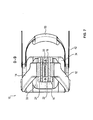
- FIG. 1 a schematic illustration of a head support 10 for operating tables according to a first embodiment is illustrated.
- the head support 10 is in particular attached to a non-illustrated operating table in order to support and securely fix the head of the patient to be operated during shoulder surgeries.
- the patient is in particular positioned on the back on the operating table, i.e. face up.
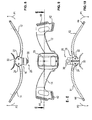
- Figure 2 a rear view and in Figure 3 a side view of the head support 10 according to Figure 1 is shown.
- Figures 4 to 7 respectively show a sectional illustration of the head support 10, wherein in Figures 4 and 5 respectively a side view, in Figure 6 a front view and in Figure 7 a bottom view is illustrated.
- Figures 8 and 9 respectively show a highly simplified illustration of the head support 10 in the open state.
- Figure 10 also shows the head support 10 in the open state as sectional illustration.
- the head support 10 includes two wing-like formed holding elements 12, 14 which are coupled to each other via a coupling element 16 such that they can be pivoted synchronously from a closed state illustrated in Figures 1 to 7 in an open state illustrated in Figures 8 to 10 .
- the coupling element 16 comprises a first cog wheel segment 18 integrally formed with the first holding element 12 and a second cog wheel segment 20 integrally formed with the second holding element 20 which mesh with each other and are thus in engagement with each other.
- the first holding element 12 is rotatably mounted about a first axis of rotation 22 and the second holding element 14 is rotatably mounted about a second axis of rotation 24. Due to the coupling via the two cog wheel segments 18, 20 it is achieved that, when one of the two holding elements 12, 14 is rotated about its respective axis of rotation 22, 24, the respective other holding element 12, 14 is correspondingly rotated along about its axis of rotation 22, 24 via the coupling. Thus, a synchronous closing and opening of the two holding elements 12, 14 is achieved, when only one of the holding elements 12, 14 is actuated.
- the cog wheel segments 18, 20 also have the effect that a stable coupling takes place so that the two holding elements 12, 14 can be used for supporting the arms of a physician in the open state.
- the physician can thus support himself on the holding elements, when he intubates the patient already supported on the operating table and with his head in the head support 10 before the surgery.
- the head support 10 comprises a fastening element 26 by means of which the head support 10 is fastenable on the operating table.
- a rail is provided at the operating table which is formed complementary to a receiving area 28 of the fastening element 26 so that the fastening element 26 can be slid on said rail.
- Via a rotary knob 30 the head support 10 can be fixed at the desired position on the rail so that undesired sliding is prevented.
- the head support 10 includes a supporting element 33 which is arranged between the cog wheel segments 18, 20 and the receiving area 32 in which the patient's head is received.
- a padding 34 is provided on which the patient's back of the head is supported.
- the supporting element 33 and/or the padding 34 are in particular arcuately shaped and thus adapted to the ergonomics of a human being's back of the head.
- the head support 10 For supporting the patient the head support 10 is arranged in the open state shown in Figures 8 to 10 so that the head can be comfortably received in the receiving area 32 and lies via the back of the head on the padding 34. Subsequently, one of the two holding elements 12, 14 is rotated in the direction of the arrow P1 or the arrow P2 and thus brought from the open in the closed stated state shown in Figures 1 to 7 . Via the coupling and via the cog wheel segments 18, 20 the other holding element 12, 14 is correspondingly moved along. In the closed state, the two holding elements 12, 14 then surround the two sides of the head so that the head is surrounded at at least three sides by the two holding elements 12, 14 together with the supporting element 33 and is thus fixed in a desired position.
- the supporting element 33 has the effect that the head is spaced from the coupling position at which the two holding elements 12, 14 are coupled via the cog wheel segments 18, 20 and can thus not be clamped. Thus, on the one hand injuries are prevented and on the other hand it is ensured that the adjustment of the holding elements 12, 14 can reliably take place.
- the two holding elements 12, 14 After the two holding elements 12, 14 have been rotated in the closed state, they can be fixed in this position in particular via two belts 40, 42.
- the belts 40, 42 are guided at the ends of the holding elements 12, 14 opposite to the cog wheel segments 18, 20 through corresponding slots 44, 46. Via velcro fasteners the belts 40, 42 can respectively be adapted in lengths to the corresponding dimensions of the received head.
- the first belt 40 is in particular guided via the forehead of the head received in the receiving area 32 and the second belt 42 is guided around the chin.
- one or a plurality of paddings 52, 54 can be arranged at each of the sides of the holding elements 12, 14 facing the head.
- the holding elements 12, 14 are in particular formed of a flexible material so that they are not rigid and thus injuries are prevented. Further, the holding elements 12, 14 can adapt to the contour of the head in a given range.
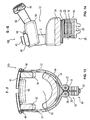
- Figure 11 shows a schematic, perspective illustration of a head support 100 according to a second embodiment. Elements having the same structure and the same function are identified with the same reference signs.
- Figure 12 a front view of the head support 100 according to Figure 11 is illustrated.
- Figures 13 to 15 respectively show a sectional illustration of the head support 100 according to Figures 11 and 12 , wherein in Figure 13 a front view, in Figure 14 a side view and in Figure 15 a back view is illustrated.
- the second embodiment differs from the first embodiment only in that the second belt 42 is arranged in another angle due to a corresponding other arrangement of the slot 46.
- only one belt 40, 42 or no belt 40, 42 at all can be provided.
- no padding 34 can be provided on the supporting element 33 and/or no paddings 48 to 54 can be provided at the holding elements 12, 14 and/or the belts 40, 42.
Landscapes
- Health & Medical Sciences (AREA)
- Public Health (AREA)
- Veterinary Medicine (AREA)
- Engineering & Computer Science (AREA)
- Biomedical Technology (AREA)
- Life Sciences & Earth Sciences (AREA)
- Animal Behavior & Ethology (AREA)
- General Health & Medical Sciences (AREA)
- Otolaryngology (AREA)
- Nursing (AREA)
- Orthopedic Medicine & Surgery (AREA)
- Heart & Thoracic Surgery (AREA)
- Vascular Medicine (AREA)
- Neurosurgery (AREA)
- Accommodation For Nursing Or Treatment Tables (AREA)
- Chair Legs, Seat Parts, And Backrests (AREA)
Claims (15)
- Support de tête pour tables d'opération,
comprenant un premier élément de maintien (12) monté pour pouvoir tourner autour d'un premier axe de rotation (22) afin d'entourer un premier côté de la tête du patient qui peut s'appuyer sur une zone d'appui (32) du support de tête (10, 100),
et un second élément de maintien (14) monté pour pouvoir tourner autour d'un second axe de rotation (24) afin d'entourer un second côté de la tête du patient,
dans lequel le premier élément de maintien (12) et le second élément de maintien (14) sont couplés l'un à l'autre dans une zone de couplage au moyen d'au moins un élément de couplage (16), de telle sorte que, lorsque l'un des éléments de maintien (12, 14) tourne, l'élément de couplage (16) tourne également avec l'autre élément de maintien (12, 14),
caractérisé en ce qu'un élément de support (33) agencé de manière fixe pour supporter la tête lorsqu'elle s'appuie sur la zone d'appui (32) est fourni entre la zone de couplage et la zone d'appui (32). - Support de tête (10, 100) selon la revendication 1, caractérisé en ce que l'élément de support (33) comprend une surface de support arquée permettant de soutenir l'arrière de la tête.
- Support de tête (10, 100) selon la revendication 1 ou 2, caractérisé en ce que l'élément de support (33) comprend un rembourrage (34).
- Support de tête (10, 100) selon l'une des revendications précédentes, caractérisé en ce que l'élément de couplage (16) comprend au moins un segment de roue dentée (18, 20).
- Support de tête (10, 100) selon l'une des revendications précédentes, caractérisé en ce que l'élément de couplage (16) comprend un premier segment de roue dentée (18) relié rigidement au premier élément de maintien (12) et un second segment de roue dentée (20) relié rigidement au second élément de maintien (14) et en ce que le premier segment de roue dentée (18) et le second segment de roue dentée (20) sont engagés l'un avec l'autre.
- Support de tête (10, 100) selon la revendication 5, caractérisé en ce que le premier segment de roue dentée (18) et le premier élément de maintien (12) et/ou le second segment de roue dentée (20) et le second élément de maintien (14) sont respectivement formés en une seule pièce.
- Support de tête (10, 100) selon l'une des revendications précédentes, caractérisé en ce que ledit premier élément de maintien (12) est une symétrie plane du second élément de maintien (14) par rapport à un plan médian du support de tête (10, 100).
- Support de tête (10, 100) selon l'une des revendications précédentes, caractérisé en ce que le support de tête (10, 100) comprend un élément d'attache (26) permettant d'attacher sur la table d'opération.
- Support de tête (10, 100) selon la revendication 8, caractérisé en ce que l'élément de couplage (16) est agencé entre l'élément d'attache (26) et l'élément de support (33).
- Support de tête (10, 100) selon l'une des revendications précédentes, caractérisé en ce qu'il comprend une première courroie (40) permettant de relier les deux éléments de maintien (12, 14).
- Support de tête (10, 100) selon la revendication 10, caractérisé en ce qu'il comprend une seconde courroie (42) permettant de relier les deux éléments de maintien (12, 14) et en ce que la première courroie (40) entoure le front du patient et la seconde courroie (42) entoure le menton du patient.
- Support de tête (10, 100) selon la revendication 10 ou 11, caractérisé en ce que la première courroie (40) et/ou la seconde courroie (42) est composée d'un matériau élastique.
- Support de tête (10, 100) selon l'une des revendications 10 à 12, caractérisé en ce que l'élément de couplage (16) est agencé au niveau d'une première partie d'extrémité des éléments de maintien (12, 14) et en ce que la première courroie (40) et/ou la seconde courroie (42) sont agencées au niveau d'une seconde portion d'extrémité du premier élément de maintien (12) opposée à la première portion d'extrémité du premier élément de maintien (12) et au niveau d'une seconde portion d'extrémité du second élément de maintien (14) opposée à la première portion d'extrémité du second élément de maintien (14).
- Support de tête (10, 100) selon l'une des revendications précédentes, caractérisé en ce que les éléments de maintien (12, 14) entourent la tête du patient sur au moins trois côtés, à l'état refermé, et en ce que les éléments de maintien (12, 14) n'entourent pas la tête du patient à l'état ouvert.
- Support de tête (10, 100) selon la revendication 14, caractérisé en ce que l'élément de couplage (16) et les éléments de maintien (12, 14) sont conçus de telle manière à ce que les éléments de maintien (12, 14) à l'état ouvert servent de supports pour les bras d'une personne prodiguant des soins au patient.
Priority Applications (8)
| Application Number | Priority Date | Filing Date | Title |
|---|---|---|---|
| EP20120190367 EP2724701B1 (fr) | 2012-10-29 | 2012-10-29 | Support de tête destiné à des tables d'opération |
| PL12190367T PL2724701T3 (pl) | 2012-10-29 | 2012-10-29 | Zagłówek do stołów operacyjnych |
| RU2013142944/12A RU2553030C2 (ru) | 2012-10-29 | 2013-09-20 | Подголовник для операционных столов |
| JP2013199648A JP5822887B2 (ja) | 2012-10-29 | 2013-09-26 | 手術台用の頭部支持体 |
| US14/058,999 US9572706B2 (en) | 2012-10-29 | 2013-10-21 | Head support for operating tables |
| CN201310498831.1A CN103784287B (zh) | 2012-10-29 | 2013-10-22 | 用于手术台的头部支架 |
| KR1020130127185A KR101608563B1 (ko) | 2012-10-29 | 2013-10-24 | 수술대의 머리지지대 |
| BRBR102013027656-1A BR102013027656A2 (pt) | 2012-10-29 | 2013-10-25 | Suporte de cabeça para mesas de operação |
Applications Claiming Priority (1)
| Application Number | Priority Date | Filing Date | Title |
|---|---|---|---|
| EP20120190367 EP2724701B1 (fr) | 2012-10-29 | 2012-10-29 | Support de tête destiné à des tables d'opération |
Publications (2)
| Publication Number | Publication Date |
|---|---|
| EP2724701A1 EP2724701A1 (fr) | 2014-04-30 |
| EP2724701B1 true EP2724701B1 (fr) | 2015-04-29 |
Family
ID=47142958
Family Applications (1)
| Application Number | Title | Priority Date | Filing Date |
|---|---|---|---|
| EP20120190367 Active EP2724701B1 (fr) | 2012-10-29 | 2012-10-29 | Support de tête destiné à des tables d'opération |
Country Status (8)
| Country | Link |
|---|---|
| US (1) | US9572706B2 (fr) |
| EP (1) | EP2724701B1 (fr) |
| JP (1) | JP5822887B2 (fr) |
| KR (1) | KR101608563B1 (fr) |
| CN (1) | CN103784287B (fr) |
| BR (1) | BR102013027656A2 (fr) |
| PL (1) | PL2724701T3 (fr) |
| RU (1) | RU2553030C2 (fr) |
Cited By (2)
| Publication number | Priority date | Publication date | Assignee | Title |
|---|---|---|---|---|
| DE202017105275U1 (de) | 2017-09-01 | 2018-12-06 | Schmitz u. Söhne GmbH & Co. Kommanditgesellschaft | Kopfstütze für Operationstische |
| US11850191B2 (en) | 2020-04-22 | 2023-12-26 | Warsaw Orthopedic, Inc. | Head support and method for use of the head support for positioning a patient relative to a surgical frame |
Families Citing this family (11)
| Publication number | Priority date | Publication date | Assignee | Title |
|---|---|---|---|---|
| DE102012214449B4 (de) * | 2012-08-14 | 2014-07-10 | Siemens Aktiengesellschaft | Patientenlagerungsvorrichtung sowie eine die Patientenlagerungsvorrichtung umfassende medizinische Bildgebungsvorrichtung |
| WO2015109086A1 (fr) * | 2014-01-15 | 2015-07-23 | The Regents Of The University Of Colorado, A Body Corporate | Adaptateur pour table d'imagerie et montant de tête |
| CN105616096B (zh) * | 2014-11-27 | 2018-09-04 | 鱼湉 | 头颈手术位置自动调整装置 |
| KR101710464B1 (ko) * | 2016-03-08 | 2017-03-13 | 순천향대학교 산학협력단 | 수술용 목 받침대 |
| RU2635444C1 (ru) * | 2016-08-25 | 2017-11-13 | Федеральное государственное автономное учреждение "Межотраслевой научно-технический комплекс "Микрохирургия глаза" имени академика С.Н. Федорова" Министерства здравоохранения Российской Федерации | Устройство для проведения офтальмохирургических пластических и реконструктивных операций на малонаселенных территориях |
| CN109259923A (zh) * | 2018-11-06 | 2019-01-25 | 桂莉 | 一种精神科疾病异常护理装置 |
| CN109925148A (zh) * | 2019-04-29 | 2019-06-25 | 窦清泉 | 一种颅脑创伤术后头位固定垫 |
| CN110327177A (zh) * | 2019-07-31 | 2019-10-15 | 上海志听医疗科技有限公司 | 一种头部固定装置 |
| JP2022550239A (ja) * | 2019-10-03 | 2022-12-01 | ビクトリア リンク リミテッド | 膨張可能なヘッドサポート |
| US20230301742A1 (en) * | 2020-08-14 | 2023-09-28 | The Research Foundation For The State University Of New York | Face shield apparatuses and systems including same |
| CN112754847B (zh) * | 2020-12-28 | 2023-03-17 | 河北医科大学第二医院 | 一种便于调节的耳鼻咽喉科用手术装置 |
Family Cites Families (21)
| Publication number | Priority date | Publication date | Assignee | Title |
|---|---|---|---|---|
| US1278251A (en) * | 1917-12-04 | 1918-09-10 | Frank Syjud | Bevel-protractor. |
| US2535559A (en) | 1949-03-15 | 1950-12-26 | Wolf Monroe | Surgical clamp |
| JPS4915434Y1 (fr) * | 1970-09-25 | 1974-04-17 | ||
| US4034748A (en) | 1975-10-28 | 1977-07-12 | Winner Stephen E | Spinal restraint device |
| JPS581447A (ja) | 1981-06-26 | 1983-01-06 | 日本電熱株式会社 | 患者移送装置 |
| US4545572A (en) | 1984-08-20 | 1985-10-08 | Ohio Medical Instrument Company, Inc. | Apparatus for holding the head of a patient for surgery |
| US5154186A (en) | 1990-04-12 | 1992-10-13 | Laurin Frederick J | Spinal restraint |
| DE4342971C1 (de) * | 1993-12-16 | 1995-03-23 | Axel Dr Dr Med Koch | Vorrichtung zur Bestimmung der Ausrichtung der Jochbeine an einem Schädel |
| US5515867A (en) | 1995-05-30 | 1996-05-14 | Orthopedic System Inc. | Head support for shoulder surgery positioner |
| US6648416B2 (en) * | 1998-08-13 | 2003-11-18 | Richard W. O'Connor | Headrest |
| US6594839B1 (en) * | 1999-04-30 | 2003-07-22 | The Cleveland Clinic Foundation | Surgical headrest |
| RU12524U1 (ru) * | 1999-07-07 | 2000-01-20 | Окружной травматологический центр | Устройство для операций на шейном отделе позвоночника |
| CA2299483A1 (fr) | 2000-01-06 | 2001-07-06 | Dan Reinstein | Appuie-tete |
| AU2659001A (en) | 2000-01-06 | 2001-07-16 | Foster, Mark Leighton | Head support |
| US7120954B2 (en) | 2000-12-19 | 2006-10-17 | Laerdal Medical Corporation | Head immobilizer |
| US6637057B2 (en) | 2000-12-19 | 2003-10-28 | Laerdal Medical Corporation | Head immobilizer |
| JP2003135446A (ja) | 2001-10-30 | 2003-05-13 | Toshiba Corp | 画像診断用寝台装置の付属品 |
| CN2582584Y (zh) | 2002-10-22 | 2003-10-29 | 李乾坤 | 全功能肩开刀架 |
| US7350250B2 (en) | 2005-01-10 | 2008-04-01 | Michael Froelich | Head positioning device |
| WO2006110703A2 (fr) | 2005-04-11 | 2006-10-19 | Skripps Thomas K | Accessoire pour la chirurgie rachidienne |
| US9254235B2 (en) | 2009-08-17 | 2016-02-09 | Kabushiki Kaisha Toshiba | Medical head restraint and medical bed system using the same |
-
2012
- 2012-10-29 PL PL12190367T patent/PL2724701T3/pl unknown
- 2012-10-29 EP EP20120190367 patent/EP2724701B1/fr active Active
-
2013
- 2013-09-20 RU RU2013142944/12A patent/RU2553030C2/ru not_active IP Right Cessation
- 2013-09-26 JP JP2013199648A patent/JP5822887B2/ja active Active
- 2013-10-21 US US14/058,999 patent/US9572706B2/en active Active
- 2013-10-22 CN CN201310498831.1A patent/CN103784287B/zh active Active
- 2013-10-24 KR KR1020130127185A patent/KR101608563B1/ko active IP Right Grant
- 2013-10-25 BR BRBR102013027656-1A patent/BR102013027656A2/pt active Search and Examination
Cited By (3)
| Publication number | Priority date | Publication date | Assignee | Title |
|---|---|---|---|---|
| DE202017105275U1 (de) | 2017-09-01 | 2018-12-06 | Schmitz u. Söhne GmbH & Co. Kommanditgesellschaft | Kopfstütze für Operationstische |
| EP3449888A1 (fr) | 2017-09-01 | 2019-03-06 | Schmitz u. Söhne GmbH & Co. Kommanditgesellschaft | Appui-tête pour table d'opération |
| US11850191B2 (en) | 2020-04-22 | 2023-12-26 | Warsaw Orthopedic, Inc. | Head support and method for use of the head support for positioning a patient relative to a surgical frame |
Also Published As
| Publication number | Publication date |
|---|---|
| JP2014087607A (ja) | 2014-05-15 |
| PL2724701T3 (pl) | 2015-10-30 |
| US20140116450A1 (en) | 2014-05-01 |
| RU2013142944A (ru) | 2015-03-27 |
| KR101608563B1 (ko) | 2016-04-01 |
| BR102013027656A2 (pt) | 2014-10-21 |
| JP5822887B2 (ja) | 2015-11-25 |
| CN103784287B (zh) | 2016-08-24 |
| RU2553030C2 (ru) | 2015-06-10 |
| CN103784287A (zh) | 2014-05-14 |
| EP2724701A1 (fr) | 2014-04-30 |
| US9572706B2 (en) | 2017-02-21 |
| KR20140056011A (ko) | 2014-05-09 |
Similar Documents
| Publication | Publication Date | Title |
|---|---|---|
| EP2724701B1 (fr) | Support de tête destiné à des tables d'opération | |
| AU2021258051B2 (en) | Nasal respiratory interface and adjustable headgear | |
| EP2693993B1 (fr) | Appareil de renfort ajustable | |
| EP2253293B1 (fr) | Protège-poignet | |
| US8646452B2 (en) | Pediatric headrest for skull stabilization and method for use of same | |
| CN108670530B (zh) | 一种医疗骨科病房用临床固定装置 | |
| KR101663807B1 (ko) | 모듈형 등받이 거치대 | |
| CN208958651U (zh) | 一种儿童脊柱检查和治疗的限位装置 | |
| KR100904765B1 (ko) | 경추고정장치 | |
| CN113288546B (zh) | 便于穿戴的乳腺外科术后托架 | |
| US20160095736A1 (en) | Splint | |
| CN215584527U (zh) | 一种肩关节外展支具 | |
| CN112716675A (zh) | 头部前倾矫正装置 | |
| CN102770037A (zh) | 用于可松释地将衣物附着到人体上的装置 | |
| CN112790903A (zh) | 膝盖固定支架 | |
| CN111388849B (zh) | 一种耳鼻喉护理用耳道给药装置 | |
| CN207506838U (zh) | 无创呼吸机鼻罩固定装置 | |
| CN209629925U (zh) | 一种可调式膝关节固定装置 | |
| CN209575089U (zh) | 可支撑下肢的轮椅 | |
| CN219814450U (zh) | 一种桡骨远端骨折固定装置 | |
| CN216258945U (zh) | 一种医学护理用肢体康复训练装置 | |
| CN211434561U (zh) | 输液固定机构 | |
| CN211095074U (zh) | 一种膝关节固定支具 | |
| CN215780634U (zh) | 一种儿童可调节静脉输液固定手板 | |
| CN215079477U (zh) | 一种骨科用腿骨纠正装置 |
Legal Events
| Date | Code | Title | Description |
|---|---|---|---|
| PUAI | Public reference made under article 153(3) epc to a published international application that has entered the european phase |
Free format text: ORIGINAL CODE: 0009012 |
|
| 17P | Request for examination filed |
Effective date: 20130415 |
|
| AK | Designated contracting states |
Kind code of ref document: A1 Designated state(s): AL AT BE BG CH CY CZ DE DK EE ES FI FR GB GR HR HU IE IS IT LI LT LU LV MC MK MT NL NO PL PT RO RS SE SI SK SM TR |
|
| AX | Request for extension of the european patent |
Extension state: BA ME |
|
| GRAP | Despatch of communication of intention to grant a patent |
Free format text: ORIGINAL CODE: EPIDOSNIGR1 |
|
| INTG | Intention to grant announced |
Effective date: 20141127 |
|
| GRAS | Grant fee paid |
Free format text: ORIGINAL CODE: EPIDOSNIGR3 |
|
| RIN1 | Information on inventor provided before grant (corrected) |
Inventor name: GE, KAIYOU Inventor name: LI, HONGQUIANG |
|
| GRAA | (expected) grant |
Free format text: ORIGINAL CODE: 0009210 |
|
| AK | Designated contracting states |
Kind code of ref document: B1 Designated state(s): AL AT BE BG CH CY CZ DE DK EE ES FI FR GB GR HR HU IE IS IT LI LT LU LV MC MK MT NL NO PL PT RO RS SE SI SK SM TR |
|
| REG | Reference to a national code |
Ref country code: GB Ref legal event code: FG4D |
|
| REG | Reference to a national code |
Ref country code: CH Ref legal event code: EP Ref country code: CH Ref legal event code: NV Representative=s name: SCHNEIDER FELDMANN AG PATENT- UND MARKENANWAEL, CH |
|
| REG | Reference to a national code |
Ref country code: DE Ref legal event code: R082 Ref document number: 602012006982 Country of ref document: DE Representative=s name: SCHAUMBURG & PARTNER PATENTANWAELTE GBR, DE Ref country code: DE Ref legal event code: R082 Ref document number: 602012006982 Country of ref document: DE Representative=s name: ZACCO DR. PETERS UND PARTNER, DE Ref country code: DE Ref legal event code: R082 Ref document number: 602012006982 Country of ref document: DE Representative=s name: ZACCO PATENTANWALTS- UND RECHTSANWALTSGESELLSC, DE |
|
| REG | Reference to a national code |
Ref country code: AT Ref legal event code: REF Ref document number: 724038 Country of ref document: AT Kind code of ref document: T Effective date: 20150515 |
|
| REG | Reference to a national code |
Ref country code: IE Ref legal event code: FG4D |
|
| REG | Reference to a national code |
Ref country code: DE Ref legal event code: R096 Ref document number: 602012006982 Country of ref document: DE Effective date: 20150611 |
|
| REG | Reference to a national code |
Ref country code: NL Ref legal event code: VDEP Effective date: 20150429 |
|
| REG | Reference to a national code |
Ref country code: AT Ref legal event code: MK05 Ref document number: 724038 Country of ref document: AT Kind code of ref document: T Effective date: 20150429 |
|
| REG | Reference to a national code |
Ref country code: LT Ref legal event code: MG4D |
|
| PG25 | Lapsed in a contracting state [announced via postgrant information from national office to epo] |
Ref country code: NL Free format text: LAPSE BECAUSE OF FAILURE TO SUBMIT A TRANSLATION OF THE DESCRIPTION OR TO PAY THE FEE WITHIN THE PRESCRIBED TIME-LIMIT Effective date: 20150429 |
|
| REG | Reference to a national code |
Ref country code: DE Ref legal event code: R082 Ref document number: 602012006982 Country of ref document: DE Representative=s name: ZACCO DR. PETERS UND PARTNER, DE Ref country code: DE Ref legal event code: R082 Ref document number: 602012006982 Country of ref document: DE Representative=s name: ZACCO PATENTANWALTS- UND RECHTSANWALTSGESELLSC, DE |
|
| REG | Reference to a national code |
Ref country code: FR Ref legal event code: PLFP Year of fee payment: 4 |
|
| PG25 | Lapsed in a contracting state [announced via postgrant information from national office to epo] |
Ref country code: LT Free format text: LAPSE BECAUSE OF FAILURE TO SUBMIT A TRANSLATION OF THE DESCRIPTION OR TO PAY THE FEE WITHIN THE PRESCRIBED TIME-LIMIT Effective date: 20150429 Ref country code: HR Free format text: LAPSE BECAUSE OF FAILURE TO SUBMIT A TRANSLATION OF THE DESCRIPTION OR TO PAY THE FEE WITHIN THE PRESCRIBED TIME-LIMIT Effective date: 20150429 Ref country code: NO Free format text: LAPSE BECAUSE OF FAILURE TO SUBMIT A TRANSLATION OF THE DESCRIPTION OR TO PAY THE FEE WITHIN THE PRESCRIBED TIME-LIMIT Effective date: 20150729 Ref country code: FI Free format text: LAPSE BECAUSE OF FAILURE TO SUBMIT A TRANSLATION OF THE DESCRIPTION OR TO PAY THE FEE WITHIN THE PRESCRIBED TIME-LIMIT Effective date: 20150429 Ref country code: PT Free format text: LAPSE BECAUSE OF FAILURE TO SUBMIT A TRANSLATION OF THE DESCRIPTION OR TO PAY THE FEE WITHIN THE PRESCRIBED TIME-LIMIT Effective date: 20150831 Ref country code: ES Free format text: LAPSE BECAUSE OF FAILURE TO SUBMIT A TRANSLATION OF THE DESCRIPTION OR TO PAY THE FEE WITHIN THE PRESCRIBED TIME-LIMIT Effective date: 20150429 |
|
| REG | Reference to a national code |
Ref country code: PL Ref legal event code: T3 |
|
| PG25 | Lapsed in a contracting state [announced via postgrant information from national office to epo] |
Ref country code: AT Free format text: LAPSE BECAUSE OF FAILURE TO SUBMIT A TRANSLATION OF THE DESCRIPTION OR TO PAY THE FEE WITHIN THE PRESCRIBED TIME-LIMIT Effective date: 20150429 Ref country code: RS Free format text: LAPSE BECAUSE OF FAILURE TO SUBMIT A TRANSLATION OF THE DESCRIPTION OR TO PAY THE FEE WITHIN THE PRESCRIBED TIME-LIMIT Effective date: 20150429 Ref country code: GR Free format text: LAPSE BECAUSE OF FAILURE TO SUBMIT A TRANSLATION OF THE DESCRIPTION OR TO PAY THE FEE WITHIN THE PRESCRIBED TIME-LIMIT Effective date: 20150730 Ref country code: LV Free format text: LAPSE BECAUSE OF FAILURE TO SUBMIT A TRANSLATION OF THE DESCRIPTION OR TO PAY THE FEE WITHIN THE PRESCRIBED TIME-LIMIT Effective date: 20150429 Ref country code: IS Free format text: LAPSE BECAUSE OF FAILURE TO SUBMIT A TRANSLATION OF THE DESCRIPTION OR TO PAY THE FEE WITHIN THE PRESCRIBED TIME-LIMIT Effective date: 20150829 |
|
| PG25 | Lapsed in a contracting state [announced via postgrant information from national office to epo] |
Ref country code: EE Free format text: LAPSE BECAUSE OF FAILURE TO SUBMIT A TRANSLATION OF THE DESCRIPTION OR TO PAY THE FEE WITHIN THE PRESCRIBED TIME-LIMIT Effective date: 20150429 Ref country code: DK Free format text: LAPSE BECAUSE OF FAILURE TO SUBMIT A TRANSLATION OF THE DESCRIPTION OR TO PAY THE FEE WITHIN THE PRESCRIBED TIME-LIMIT Effective date: 20150429 |
|
| REG | Reference to a national code |
Ref country code: DE Ref legal event code: R097 Ref document number: 602012006982 Country of ref document: DE |
|
| PG25 | Lapsed in a contracting state [announced via postgrant information from national office to epo] |
Ref country code: SK Free format text: LAPSE BECAUSE OF FAILURE TO SUBMIT A TRANSLATION OF THE DESCRIPTION OR TO PAY THE FEE WITHIN THE PRESCRIBED TIME-LIMIT Effective date: 20150429 Ref country code: RO Free format text: LAPSE BECAUSE OF NON-PAYMENT OF DUE FEES Effective date: 20150429 |
|
| PLBE | No opposition filed within time limit |
Free format text: ORIGINAL CODE: 0009261 |
|
| STAA | Information on the status of an ep patent application or granted ep patent |
Free format text: STATUS: NO OPPOSITION FILED WITHIN TIME LIMIT |
|
| 26N | No opposition filed |
Effective date: 20160201 |
|
| PG25 | Lapsed in a contracting state [announced via postgrant information from national office to epo] |
Ref country code: LU Free format text: LAPSE BECAUSE OF FAILURE TO SUBMIT A TRANSLATION OF THE DESCRIPTION OR TO PAY THE FEE WITHIN THE PRESCRIBED TIME-LIMIT Effective date: 20151029 Ref country code: SI Free format text: LAPSE BECAUSE OF FAILURE TO SUBMIT A TRANSLATION OF THE DESCRIPTION OR TO PAY THE FEE WITHIN THE PRESCRIBED TIME-LIMIT Effective date: 20150429 |
|
| PG25 | Lapsed in a contracting state [announced via postgrant information from national office to epo] |
Ref country code: MC Free format text: LAPSE BECAUSE OF FAILURE TO SUBMIT A TRANSLATION OF THE DESCRIPTION OR TO PAY THE FEE WITHIN THE PRESCRIBED TIME-LIMIT Effective date: 20150429 |
|
| REG | Reference to a national code |
Ref country code: IE Ref legal event code: MM4A |
|
| PG25 | Lapsed in a contracting state [announced via postgrant information from national office to epo] |
Ref country code: BE Free format text: LAPSE BECAUSE OF FAILURE TO SUBMIT A TRANSLATION OF THE DESCRIPTION OR TO PAY THE FEE WITHIN THE PRESCRIBED TIME-LIMIT Effective date: 20150429 |
|
| REG | Reference to a national code |
Ref country code: FR Ref legal event code: PLFP Year of fee payment: 5 |
|
| PG25 | Lapsed in a contracting state [announced via postgrant information from national office to epo] |
Ref country code: IE Free format text: LAPSE BECAUSE OF NON-PAYMENT OF DUE FEES Effective date: 20151029 |
|
| PG25 | Lapsed in a contracting state [announced via postgrant information from national office to epo] |
Ref country code: BG Free format text: LAPSE BECAUSE OF FAILURE TO SUBMIT A TRANSLATION OF THE DESCRIPTION OR TO PAY THE FEE WITHIN THE PRESCRIBED TIME-LIMIT Effective date: 20150429 Ref country code: SM Free format text: LAPSE BECAUSE OF FAILURE TO SUBMIT A TRANSLATION OF THE DESCRIPTION OR TO PAY THE FEE WITHIN THE PRESCRIBED TIME-LIMIT Effective date: 20150429 Ref country code: HU Free format text: LAPSE BECAUSE OF FAILURE TO SUBMIT A TRANSLATION OF THE DESCRIPTION OR TO PAY THE FEE WITHIN THE PRESCRIBED TIME-LIMIT; INVALID AB INITIO Effective date: 20121029 |
|
| PG25 | Lapsed in a contracting state [announced via postgrant information from national office to epo] |
Ref country code: CY Free format text: LAPSE BECAUSE OF FAILURE TO SUBMIT A TRANSLATION OF THE DESCRIPTION OR TO PAY THE FEE WITHIN THE PRESCRIBED TIME-LIMIT Effective date: 20150429 Ref country code: SE Free format text: LAPSE BECAUSE OF FAILURE TO SUBMIT A TRANSLATION OF THE DESCRIPTION OR TO PAY THE FEE WITHIN THE PRESCRIBED TIME-LIMIT Effective date: 20150429 |
|
| PG25 | Lapsed in a contracting state [announced via postgrant information from national office to epo] |
Ref country code: MT Free format text: LAPSE BECAUSE OF FAILURE TO SUBMIT A TRANSLATION OF THE DESCRIPTION OR TO PAY THE FEE WITHIN THE PRESCRIBED TIME-LIMIT Effective date: 20150429 |
|
| REG | Reference to a national code |
Ref country code: FR Ref legal event code: PLFP Year of fee payment: 6 |
|
| PG25 | Lapsed in a contracting state [announced via postgrant information from national office to epo] |
Ref country code: MK Free format text: LAPSE BECAUSE OF FAILURE TO SUBMIT A TRANSLATION OF THE DESCRIPTION OR TO PAY THE FEE WITHIN THE PRESCRIBED TIME-LIMIT Effective date: 20150429 |
|
| REG | Reference to a national code |
Ref country code: FR Ref legal event code: PLFP Year of fee payment: 7 |
|
| PG25 | Lapsed in a contracting state [announced via postgrant information from national office to epo] |
Ref country code: TR Free format text: LAPSE BECAUSE OF FAILURE TO SUBMIT A TRANSLATION OF THE DESCRIPTION OR TO PAY THE FEE WITHIN THE PRESCRIBED TIME-LIMIT Effective date: 20150429 Ref country code: AL Free format text: LAPSE BECAUSE OF FAILURE TO SUBMIT A TRANSLATION OF THE DESCRIPTION OR TO PAY THE FEE WITHIN THE PRESCRIBED TIME-LIMIT Effective date: 20150429 |
|
| REG | Reference to a national code |
Ref country code: CH Ref legal event code: PFA Owner name: MAQUET GMBH, DE Free format text: FORMER OWNER: MAQUET GMBH, DE |
|
| PGFP | Annual fee paid to national office [announced via postgrant information from national office to epo] |
Ref country code: CZ Payment date: 20200929 Year of fee payment: 9 |
|
| PGFP | Annual fee paid to national office [announced via postgrant information from national office to epo] |
Ref country code: CH Payment date: 20200918 Year of fee payment: 9 Ref country code: PL Payment date: 20200923 Year of fee payment: 9 |
|
| REG | Reference to a national code |
Ref country code: DE Ref legal event code: R082 Ref document number: 602012006982 Country of ref document: DE Representative=s name: ZACCO LEGAL RECHTSANWALTSGESELLSCHAFT MBH, DE |
|
| REG | Reference to a national code |
Ref country code: CH Ref legal event code: PL |
|
| PG25 | Lapsed in a contracting state [announced via postgrant information from national office to epo] |
Ref country code: CZ Free format text: LAPSE BECAUSE OF NON-PAYMENT OF DUE FEES Effective date: 20211029 |
|
| PG25 | Lapsed in a contracting state [announced via postgrant information from national office to epo] |
Ref country code: LI Free format text: LAPSE BECAUSE OF NON-PAYMENT OF DUE FEES Effective date: 20211031 Ref country code: CH Free format text: LAPSE BECAUSE OF NON-PAYMENT OF DUE FEES Effective date: 20211031 |
|
| PG25 | Lapsed in a contracting state [announced via postgrant information from national office to epo] |
Ref country code: PL Free format text: LAPSE BECAUSE OF NON-PAYMENT OF DUE FEES Effective date: 20211029 |
|
| P01 | Opt-out of the competence of the unified patent court (upc) registered |
Effective date: 20230526 |
|
| PGFP | Annual fee paid to national office [announced via postgrant information from national office to epo] |
Ref country code: GB Payment date: 20230914 Year of fee payment: 12 |
|
| PGFP | Annual fee paid to national office [announced via postgrant information from national office to epo] |
Ref country code: FR Payment date: 20230914 Year of fee payment: 12 |
|
| PGFP | Annual fee paid to national office [announced via postgrant information from national office to epo] |
Ref country code: IT Payment date: 20231011 Year of fee payment: 12 Ref country code: DE Payment date: 20230915 Year of fee payment: 12 |