EP2724385B1 - Procede de traitement d'une cellule photovoltaïque a heterojonction - Google Patents
Procede de traitement d'une cellule photovoltaïque a heterojonction Download PDFInfo
- Publication number
- EP2724385B1 EP2724385B1 EP12741094.2A EP12741094A EP2724385B1 EP 2724385 B1 EP2724385 B1 EP 2724385B1 EP 12741094 A EP12741094 A EP 12741094A EP 2724385 B1 EP2724385 B1 EP 2724385B1
- Authority
- EP
- European Patent Office
- Prior art keywords
- cell
- layer
- photovoltaic cell
- heating
- passivation
- Prior art date
- Legal status (The legal status is an assumption and is not a legal conclusion. Google has not performed a legal analysis and makes no representation as to the accuracy of the status listed.)
- Active
Links
- 238000000034 method Methods 0.000 title claims description 21
- 238000002161 passivation Methods 0.000 claims description 21
- 238000005286 illumination Methods 0.000 claims description 20
- 229910021417 amorphous silicon Inorganic materials 0.000 claims description 19
- 238000010438 heat treatment Methods 0.000 claims description 18
- 230000004907 flux Effects 0.000 claims description 15
- ZOXJGFHDIHLPTG-UHFFFAOYSA-N Boron Chemical group [B] ZOXJGFHDIHLPTG-UHFFFAOYSA-N 0.000 claims description 10
- 229910021419 crystalline silicon Inorganic materials 0.000 claims description 9
- 239000002184 metal Substances 0.000 claims description 4
- 230000003667 anti-reflective effect Effects 0.000 claims description 2
- 230000003019 stabilising effect Effects 0.000 claims 1
- 239000010410 layer Substances 0.000 description 35
- XUIMIQQOPSSXEZ-UHFFFAOYSA-N Silicon Chemical group [Si] XUIMIQQOPSSXEZ-UHFFFAOYSA-N 0.000 description 10
- 229910052796 boron Inorganic materials 0.000 description 7
- 229910052710 silicon Inorganic materials 0.000 description 7
- 239000010703 silicon Substances 0.000 description 7
- 238000004140 cleaning Methods 0.000 description 5
- 239000000758 substrate Substances 0.000 description 5
- 239000012792 core layer Substances 0.000 description 4
- 238000001465 metallisation Methods 0.000 description 4
- 239000004065 semiconductor Substances 0.000 description 4
- 239000002800 charge carrier Substances 0.000 description 3
- 238000006243 chemical reaction Methods 0.000 description 3
- 230000007423 decrease Effects 0.000 description 3
- 230000007547 defect Effects 0.000 description 3
- 238000000151 deposition Methods 0.000 description 3
- 230000008021 deposition Effects 0.000 description 3
- 230000000694 effects Effects 0.000 description 3
- 239000000463 material Substances 0.000 description 3
- 238000000137 annealing Methods 0.000 description 2
- 239000012535 impurity Substances 0.000 description 2
- 238000009434 installation Methods 0.000 description 2
- 238000004519 manufacturing process Methods 0.000 description 2
- UFHFLCQGNIYNRP-UHFFFAOYSA-N Hydrogen Chemical compound [H][H] UFHFLCQGNIYNRP-UHFFFAOYSA-N 0.000 description 1
- QVGXLLKOCUKJST-UHFFFAOYSA-N atomic oxygen Chemical compound [O] QVGXLLKOCUKJST-UHFFFAOYSA-N 0.000 description 1
- 230000015572 biosynthetic process Effects 0.000 description 1
- 230000015556 catabolic process Effects 0.000 description 1
- 238000003693 cell processing method Methods 0.000 description 1
- 238000006731 degradation reaction Methods 0.000 description 1
- 230000001419 dependent effect Effects 0.000 description 1
- 238000010586 diagram Methods 0.000 description 1
- 239000000539 dimer Substances 0.000 description 1
- 230000005284 excitation Effects 0.000 description 1
- 229910052736 halogen Inorganic materials 0.000 description 1
- 150000002367 halogens Chemical class 0.000 description 1
- 229910052739 hydrogen Inorganic materials 0.000 description 1
- 239000001257 hydrogen Substances 0.000 description 1
- 239000002923 metal particle Substances 0.000 description 1
- 239000011146 organic particle Substances 0.000 description 1
- 150000002926 oxygen Chemical class 0.000 description 1
- 229910052760 oxygen Inorganic materials 0.000 description 1
- 239000001301 oxygen Substances 0.000 description 1
- 230000035515 penetration Effects 0.000 description 1
- 230000001737 promoting effect Effects 0.000 description 1
- 238000005215 recombination Methods 0.000 description 1
- 230000006798 recombination Effects 0.000 description 1
- 230000006641 stabilisation Effects 0.000 description 1
- 238000011105 stabilization Methods 0.000 description 1
Images

Classifications
-
- H—ELECTRICITY
- H01—ELECTRIC ELEMENTS
- H01L—SEMICONDUCTOR DEVICES NOT COVERED BY CLASS H10
- H01L31/00—Semiconductor devices sensitive to infrared radiation, light, electromagnetic radiation of shorter wavelength or corpuscular radiation and specially adapted either for the conversion of the energy of such radiation into electrical energy or for the control of electrical energy by such radiation; Processes or apparatus specially adapted for the manufacture or treatment thereof or of parts thereof; Details thereof
- H01L31/04—Semiconductor devices sensitive to infrared radiation, light, electromagnetic radiation of shorter wavelength or corpuscular radiation and specially adapted either for the conversion of the energy of such radiation into electrical energy or for the control of electrical energy by such radiation; Processes or apparatus specially adapted for the manufacture or treatment thereof or of parts thereof; Details thereof adapted as photovoltaic [PV] conversion devices
- H01L31/06—Semiconductor devices sensitive to infrared radiation, light, electromagnetic radiation of shorter wavelength or corpuscular radiation and specially adapted either for the conversion of the energy of such radiation into electrical energy or for the control of electrical energy by such radiation; Processes or apparatus specially adapted for the manufacture or treatment thereof or of parts thereof; Details thereof adapted as photovoltaic [PV] conversion devices characterised by potential barriers
- H01L31/072—Semiconductor devices sensitive to infrared radiation, light, electromagnetic radiation of shorter wavelength or corpuscular radiation and specially adapted either for the conversion of the energy of such radiation into electrical energy or for the control of electrical energy by such radiation; Processes or apparatus specially adapted for the manufacture or treatment thereof or of parts thereof; Details thereof adapted as photovoltaic [PV] conversion devices characterised by potential barriers the potential barriers being only of the PN heterojunction type
- H01L31/0745—Semiconductor devices sensitive to infrared radiation, light, electromagnetic radiation of shorter wavelength or corpuscular radiation and specially adapted either for the conversion of the energy of such radiation into electrical energy or for the control of electrical energy by such radiation; Processes or apparatus specially adapted for the manufacture or treatment thereof or of parts thereof; Details thereof adapted as photovoltaic [PV] conversion devices characterised by potential barriers the potential barriers being only of the PN heterojunction type comprising a AIVBIV heterojunction, e.g. Si/Ge, SiGe/Si or Si/SiC solar cells
- H01L31/0747—Semiconductor devices sensitive to infrared radiation, light, electromagnetic radiation of shorter wavelength or corpuscular radiation and specially adapted either for the conversion of the energy of such radiation into electrical energy or for the control of electrical energy by such radiation; Processes or apparatus specially adapted for the manufacture or treatment thereof or of parts thereof; Details thereof adapted as photovoltaic [PV] conversion devices characterised by potential barriers the potential barriers being only of the PN heterojunction type comprising a AIVBIV heterojunction, e.g. Si/Ge, SiGe/Si or Si/SiC solar cells comprising a heterojunction of crystalline and amorphous materials, e.g. heterojunction with intrinsic thin layer
-
- H—ELECTRICITY
- H01—ELECTRIC ELEMENTS
- H01L—SEMICONDUCTOR DEVICES NOT COVERED BY CLASS H10
- H01L31/00—Semiconductor devices sensitive to infrared radiation, light, electromagnetic radiation of shorter wavelength or corpuscular radiation and specially adapted either for the conversion of the energy of such radiation into electrical energy or for the control of electrical energy by such radiation; Processes or apparatus specially adapted for the manufacture or treatment thereof or of parts thereof; Details thereof
- H01L31/02—Details
- H01L31/0216—Coatings
- H01L31/02161—Coatings for devices characterised by at least one potential jump barrier or surface barrier
- H01L31/02167—Coatings for devices characterised by at least one potential jump barrier or surface barrier for solar cells
- H01L31/02168—Coatings for devices characterised by at least one potential jump barrier or surface barrier for solar cells the coatings being antireflective or having enhancing optical properties for the solar cells
-
- H—ELECTRICITY
- H01—ELECTRIC ELEMENTS
- H01L—SEMICONDUCTOR DEVICES NOT COVERED BY CLASS H10
- H01L31/00—Semiconductor devices sensitive to infrared radiation, light, electromagnetic radiation of shorter wavelength or corpuscular radiation and specially adapted either for the conversion of the energy of such radiation into electrical energy or for the control of electrical energy by such radiation; Processes or apparatus specially adapted for the manufacture or treatment thereof or of parts thereof; Details thereof
- H01L31/02—Details
- H01L31/0224—Electrodes
- H01L31/022408—Electrodes for devices characterised by at least one potential jump barrier or surface barrier
- H01L31/022425—Electrodes for devices characterised by at least one potential jump barrier or surface barrier for solar cells
- H01L31/022433—Particular geometry of the grid contacts
-
- H—ELECTRICITY
- H01—ELECTRIC ELEMENTS
- H01L—SEMICONDUCTOR DEVICES NOT COVERED BY CLASS H10
- H01L31/00—Semiconductor devices sensitive to infrared radiation, light, electromagnetic radiation of shorter wavelength or corpuscular radiation and specially adapted either for the conversion of the energy of such radiation into electrical energy or for the control of electrical energy by such radiation; Processes or apparatus specially adapted for the manufacture or treatment thereof or of parts thereof; Details thereof
- H01L31/18—Processes or apparatus specially adapted for the manufacture or treatment of these devices or of parts thereof
- H01L31/1804—Processes or apparatus specially adapted for the manufacture or treatment of these devices or of parts thereof comprising only elements of Group IV of the Periodic Table
-
- H—ELECTRICITY
- H01—ELECTRIC ELEMENTS
- H01L—SEMICONDUCTOR DEVICES NOT COVERED BY CLASS H10
- H01L31/00—Semiconductor devices sensitive to infrared radiation, light, electromagnetic radiation of shorter wavelength or corpuscular radiation and specially adapted either for the conversion of the energy of such radiation into electrical energy or for the control of electrical energy by such radiation; Processes or apparatus specially adapted for the manufacture or treatment thereof or of parts thereof; Details thereof
- H01L31/18—Processes or apparatus specially adapted for the manufacture or treatment of these devices or of parts thereof
- H01L31/186—Particular post-treatment for the devices, e.g. annealing, impurity gettering, short-circuit elimination, recrystallisation
- H01L31/1864—Annealing
-
- H—ELECTRICITY
- H01—ELECTRIC ELEMENTS
- H01L—SEMICONDUCTOR DEVICES NOT COVERED BY CLASS H10
- H01L31/00—Semiconductor devices sensitive to infrared radiation, light, electromagnetic radiation of shorter wavelength or corpuscular radiation and specially adapted either for the conversion of the energy of such radiation into electrical energy or for the control of electrical energy by such radiation; Processes or apparatus specially adapted for the manufacture or treatment thereof or of parts thereof; Details thereof
- H01L31/18—Processes or apparatus specially adapted for the manufacture or treatment of these devices or of parts thereof
- H01L31/20—Processes or apparatus specially adapted for the manufacture or treatment of these devices or of parts thereof such devices or parts thereof comprising amorphous semiconductor materials
- H01L31/208—Particular post-treatment of the devices, e.g. annealing, short-circuit elimination
-
- Y—GENERAL TAGGING OF NEW TECHNOLOGICAL DEVELOPMENTS; GENERAL TAGGING OF CROSS-SECTIONAL TECHNOLOGIES SPANNING OVER SEVERAL SECTIONS OF THE IPC; TECHNICAL SUBJECTS COVERED BY FORMER USPC CROSS-REFERENCE ART COLLECTIONS [XRACs] AND DIGESTS
- Y02—TECHNOLOGIES OR APPLICATIONS FOR MITIGATION OR ADAPTATION AGAINST CLIMATE CHANGE
- Y02E—REDUCTION OF GREENHOUSE GAS [GHG] EMISSIONS, RELATED TO ENERGY GENERATION, TRANSMISSION OR DISTRIBUTION
- Y02E10/00—Energy generation through renewable energy sources
- Y02E10/50—Photovoltaic [PV] energy
- Y02E10/547—Monocrystalline silicon PV cells
-
- Y—GENERAL TAGGING OF NEW TECHNOLOGICAL DEVELOPMENTS; GENERAL TAGGING OF CROSS-SECTIONAL TECHNOLOGIES SPANNING OVER SEVERAL SECTIONS OF THE IPC; TECHNICAL SUBJECTS COVERED BY FORMER USPC CROSS-REFERENCE ART COLLECTIONS [XRACs] AND DIGESTS
- Y02—TECHNOLOGIES OR APPLICATIONS FOR MITIGATION OR ADAPTATION AGAINST CLIMATE CHANGE
- Y02P—CLIMATE CHANGE MITIGATION TECHNOLOGIES IN THE PRODUCTION OR PROCESSING OF GOODS
- Y02P70/00—Climate change mitigation technologies in the production process for final industrial or consumer products
- Y02P70/50—Manufacturing or production processes characterised by the final manufactured product
Definitions
- the invention relates to a method of treating photovoltaic cells to improve and stabilize their performance.
- the heterojunction photovoltaic cells consist of the combination of two semiconductor materials: crystalline silicon and amorphous silicon, as opposed to homojunction cells constituted by combining two zones of the same material.
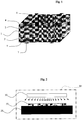
- a heterojunction cell comprises, with reference to figure 1 a crystalline silicon core layer 1 on and under which two amorphous silicon passivation layers 2 and 3 are arranged, ie an upper layer 2 and a lower layer 3.
- the silicon substrate used in the central layer 1 is a N-type mono-crystalline (CZ or FZ) type substrate, that is to say in particular without any boron atoms in the volume, except in the state. of traces (the trace state is defined in the present invention as a concentration of boron, denoted [B], between 0 and 1.10 16 at / cm 3 ).
- the passivation layers 2 and 3 are made of hydrogenated amorphous silicon (a-Si: H).
- the crystalline silicon substrate 1 must contain as few impurities as possible to maximize the performance of the photovoltaic cell.
- the interface between the crystalline silicon 1 and the amorphous silicon layers 2 and 3 a-Si: H must be the most perfectly cleaned and passivated possible before deposition in order to guarantee a very good voltage across the cell. .
- These cleanings are intended to eliminate organic and metal particles, but also to saturate all residual surface surface defects in hydrogen.
- a number of different cleanings exist, more or less effective to improve passivation.
- passivation can be improved by playing on the nature of the amorphous silicon layer 2-3, its thickness and its doping.
- Each layer of amorphous silicon 2-3 is covered with a layer, respectively upper 4 and lower 5, of an electrically conductive transparent oxide.
- Metal electrodes 6 are disposed on the free face of the electrically conductive transparent oxide layer 4, called the "front face” as intended to receive the light flux in use, and metal electrodes 7 are arranged on the free face of the layer 5 of electrically conductive transparent oxide, called “back face”, as opposed to the front face.
- the electrodes 6 consist of a metal gate, in order to let the photons pass to the silicon layers 1, 2 and 3.
- the electrodes 7 may be either a grid (like the electrodes 6) or a continuous layer. In this case, the photons can not pass through this opaque layer to join the silicon layers 1, 2 and 3.
- this article shows ( figure 1b ), that the evolution of this coefficient as a function of the time under illumination is not very good for the a-Si: H / c-Si (111) and for the a-Si: H / c-Si (100) , since after a slight improvement, it declines after 6 hours.
- the patent document JP 2007 294830 A (Referenced D3 hereinafter) relates to a process for treating n-type heterojunction photovoltaic cells comprising a crystalline silicon core layer and in which are arranged hydrogenated amorphous silicon passivation layers. D3 describes a step of heating the photovoltaic cell at high temperature, between 190 ° C and 390 ° C for an illumination time with a luminous flux for a very short period of less than 60 seconds.
- the Applicant has found that such a treatment could be adapted to improve the efficiency of this cell, even though this cell does not contain any boron, except in the trace state.
- the object of the invention is therefore to propose a method of treating N-type photovoltaic cells without a boron.
- the invention provides a method according to claim 1.
- the photovoltaic cell processing method comprises a first step of supplying an N-type heterojunction photovoltaic cell, that is to say free of boron atoms, except in the form of traces ( Bore concentration, denoted [B], between 0 and 1.10 16 at / cm 3 ).
- the cell comprising a crystalline silicon core layer 1 on and beneath which are disposed two passivation layers 2 and 3 of hydrogenated amorphous silicon.
- the amorphous silicon layers 2 and / or 3 is doped or micro-doped.
- the layer 2 may be more particularly doped (or micro-doped) by a P-type doping and the layer 3 may be doped (or micro-doped) by an N-type doping.
- the layer 3 may be intrinsic, that is to say undoped (an intrinsic semiconductor is a semiconductor material whose electrical behavior depends only on its structure, and not the addition of impurities as in the case of doping.
- an intrinsic semiconductor is a semiconductor material whose electrical behavior depends only on its structure, and not the addition of impurities as in the case of doping.
- the charge carriers are only created by crystalline defects and by thermal excitation The number of electrons in the conduction band is equal to the number of holes in the valence band).
- the amorphous silicon layers 2 and / or 3 have a thickness less than or equal to 35 nm.
- the thickness is advantageously between 15 and 20 nm.
- the thickness is advantageously less than or equal to 10 nm.
- the cell is heated for a determined duration of treatment, while subjecting the photovoltaic cell to a determined luminous flux.
- the temperature of the heating step under illumination is between 55 ° C and 80 ° C.
- This heating step under illumination carried out during the process of treatment of photovoltaic cells N type is not preceded by an annealing step (for example at a temperature of 220 ° C) for a long time.
- the only annealing step that can be carried out at a temperature of the order of 200 ° C. is that carried out to manufacture the metallizations of the cell.
- the treatment can be done in the open air or in a heating chamber, such as an oven. It is useless to carry out the treatment in a chamber with pressure, atmosphere or controlled hydrometry.
- FIG. 2 A simplified diagram of the device used is presented in figure 2 .
- the cell 10 is deposited on a heating plate 20 and under a light source 30.
- heating plate 20 may be replaced by an oven 40 at the desired temperature.
- the invention described is intended to further improve the surface passivation for a given active layer / cleaning layer couple, without affecting the cleaning processes or the nature of the already widely known layers.
- the illumination under temperature is done after the steps of cleaning and deposition of the passivating layers 2 and 3. It can also be done indifferently during manufacture of the cell (layers 4 - 5 and / or electrodes 6 - 7 not deposited), or on a completed cell (layers 4 - 5 and electrodes 6 - 7 deposited).
- the luminous flux can be applied indifferently via the front face or the rear face.
- an opaque metallization is used on the rear face (continuous metallic layer for example)
- the illumination must obligatorily be applied on the front face.
- the treatment time according to the invention is between 30 minutes and 12 hours.
- the treatment time is about 10 hours for a luminous flux of at least 100 W / m 2 , preferably greater than or equal to 250 W / m 2 , advantageously greater than or equal to 500 W / m 2 .
- the cell Preferably, it is proposed to illuminate the cell with a halogen greater than or equal to 500W of power.
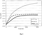
- a gain in passivation is observed regardless of the energy of the incident illumination. But the lower the intensity of illumination decreases, the passivation gain will be low and above all, in view of an industrialization of the process, the kinetics of the reaction will be reduced. So, as shown in figure 4 , the power of illumination has a decisive effect on the intensity and kinetics of passivation gain.
- illuminated cells with a luminous flux intensity of 3.5 A (solid line curve) and 4 A (dashed curve) saturate much faster than an illuminated cell with a luminous flux intensity. 5 A (point curve), and a lower passivation value.
- the high limit of illumination power to be applied it is necessary to take into account the heating of the cell generated by the illumination. Indeed, the N-type heterojunction cells degrade for temperatures greater than or equal to 200 ° C. It must therefore be ensured that the intensity of the incident luminous flux is limited in terms of heating, because this is added to the heating produced by the hotplate or the oven.
- the heating temperature of the plate or furnace is between 20 and 200 ° C, preferably between 35 and 80 ° C. This depends strongly on the type of substrate and the type of passivation layer used.
- the N-type heterojunction photovoltaic cell may also be of the RCC type, that is to say that all the metallizations and active layers are grouped on the rear face of the cell.
- the rear surface can then be the only passivated by a hydrogenated amorphous layer deposition.
- the deposit on the front face is therefore indifferent, provided that it is transparent as much as possible to the intensity of the incident luminous flux and that it ensures good surface passivation.
- the method according to the invention is advantageously continuous, but it can be sequential, that is to say that it can be interrupted and then resumed.
- the N-type heterojunction photovoltaic cell provided may include an antireflective layer thereby promoting the penetration of photons into the cell.
Landscapes
- Engineering & Computer Science (AREA)
- Microelectronics & Electronic Packaging (AREA)
- Physics & Mathematics (AREA)
- Condensed Matter Physics & Semiconductors (AREA)
- Electromagnetism (AREA)
- General Physics & Mathematics (AREA)
- Computer Hardware Design (AREA)
- Power Engineering (AREA)
- Life Sciences & Earth Sciences (AREA)
- Sustainable Energy (AREA)
- Manufacturing & Machinery (AREA)
- Sustainable Development (AREA)
- Photovoltaic Devices (AREA)
Description
- L'invention se rapporte à un procédé de traitement de cellules photovoltaïques pour améliorer et stabiliser leur rendement.
- Les cellules photovoltaïques à hétérojonction sont constituées par l'association de deux matériaux semi-conducteurs : silicium cristallin et silicium amorphe, par opposition aux cellules à homojonction constituées en associant deux zones du même matériau.
- Plus particulièrement, une cellule à hétérojonction comprend, en référence à la
figure 1 , une couche centrale 1 en silicium cristallin sur et sous laquelle sont disposées deux couches 2 et 3, dites « de passivation » en silicium amorphe, c'est-à-dire une couche supérieure 2 et une couche inférieure 3. - Le substrat silicium utilisé en couche centrale 1 est un substrat de type mono-cristallin (CZ ou FZ), de type N, c'est-à-dire en particulier dépourvu d'atomes de Bore dans le volume, sauf à l'état de traces (l'état de trace est défini, dans la présente invention, comme une concentration de Bore, notée [B], comprise entre 0 et 1.1016at/cm3).
- Dans le cadre de l'invention, les couches de passivation 2 et 3 sont en silicium amorphe hydrogéné (a-Si :H).
- Le substrat en silicium cristallin 1 doit contenir le moins d'impuretés possibles pour maximiser les performances de la cellule photovoltaïque. De la même manière, l'interface entre le silicium cristallin 1 et les couches 2 et 3 en silicium amorphe a-Si :H doit être la plus parfaitement nettoyée et passivée possible avant dépôt afin de garantir une très bonne tension aux bornes de la cellule. Ces nettoyages ont pour objectif d'éliminer les particules organiques et métalliques, mais aussi de saturer en hydrogène tous les défauts de surface résiduels en surface. Un certain nombre de nettoyages différents existent, plus ou moins efficaces pour améliorer la passivation. De la même manière, la passivation peut être améliorée en jouant sur la nature de la couche de silicium amorphe 2-3, son épaisseur et son dopage.
- Chaque couche de silicium amorphe 2-3 est recouverte d'une couche, respectivement supérieure 4 et inférieure 5, d'un oxyde transparent conducteur électrique.
- Des électrodes métalliques 6 sont disposées sur la face libre de la couche 4 d'oxyde transparent conducteur électrique, dite « face avant » car destinée à recevoir le flux lumineux en utilisation, et des électrodes métalliques 7 sont disposées sur la face libre de la couche 5 d'oxyde transparent conducteur électrique, dite « face arrière », par opposition à la face avant.
- Les électrodes 6 sont constituées d'une grille métallique, afin de laisser passer les photons vers les couches de silicium 1, 2 et 3.
- Les électrodes 7 peuvent être soit une grille (comme les électrodes 6), soit une couche continue. Dans ce cas, les photons ne peuvent pas passer à travers cette couche opaque pour rejoindre les couches de silicium 1, 2 et 3.
- L'article de De Wolf et al. (Physical Review B, vol. 83, no. 23, 7 juin 2011, pages 233301-1 - 233301-4, XP55025598) étudie l'influence de la dégradation induite par le rayonnement lumineux (LID) sur une surface en silicium cristallin passivée par un silicium amorphe hydrogéné. Le but de cette étude est d'analyser la nature et la stabilité des défauts volumiques et d'interface du silicium amorphe par le biais du paramètre τeff (durée de vie des porteurs de charge) qui détermine seulement la qualité de la passivation. Cet article ne propose pas d'amélioration, ni même de stabilisation des performances (en particulier du rendement) d'une cellule photovoltaïque à hétérojonction. Au contraire, cet article montre (
figure 1b ), que l'évolution de ce coefficient en fonction du temps sous illumination n'est pas très bonne pour le a-Si :H/c-Si(111) et pour le a-Si :H/c-Si(100), puisqu'après une légère amélioration, il décline au bout de 6 heures. - Afin d'améliorer le rendement d'une cellule photovoltaïque, il a déjà été proposé de soumettre la cellule à un traitement thermique (chauffage ce la cellule à une température comprise entre 50°C et 230°C) pendant une mise sous tension de la cellule. Ce type de traitement a toujours été réservé aux cellules constituées de silicium enrichi en atome de Bore. En effet, de telles cellules peuvent avoir un rendement de conversion énergétique qui diminue au cours de leur utilisation (c'est-à-dire lorsqu'elles sont éclairées). Cet effet est lié à la formation, lors de l'éclairement, de complexes qui associent un atome de bore en position substitutionnelle (Bs) et un dimère d'oxygène (Oi2). Lors de l'éclairement, le dimère mobile d'oxygène diffuse vers l'atome de bore immobile. Le complexe formé introduit un niveau en énergie profond dans la bande interdite du silicium, qui permet la recombinaison des charges libres, et par conséquent diminue la durée de vie des porteurs de charges et le rendement de conversion énergétique de la cellule.
- Le document de brevet
JP 2007 294830 A - Pour une cellule à hétérojonction de type N (c'est-à-dire dont le substrat de silicium utilisé pour la couche centrale 1 est dépourvu de Bore, sauf à l'état de trace), la Demanderesse s'est aperçu qu'un tel traitement pouvait être adapté pour améliorer le rendement de cette cellule, alors même que cette cellule ne contient pas de Bore, sauf à l'état de trace.
- L'invention a donc pour objet de proposer un procédé de traitement de cellules photovoltaïques de type N dépourvu de Bore.
- A cette fin, l'invention propose un procédé selon la revendication 1.
- D'autres modes de réalisation sont définis dans les revendications dépendantes 2 - 6.
- D'autres caractéristiques de l'invention seront énoncées dans la description détaillée ci-après, faite en référence aux figures annexées qui représentent, respectivement :
- la
figure 1 , une vue schématique en perspective d'une cellule à hétérojonction utilisée dans le cadre de l'invention ; - la
figure 2 , une vue schématique en coupe d'une installation pour mettre en oeuvre le procédé selon l'invention ; - la
figure 3 , un graphique illustrant le gain en passivation d'une cellule à hétérojonction subissant un traitement selon l'invention ; et - la
figure 4 , un graphique illustrant l'impact de l'intensité du flux d'illumination incident sur le gain final en passivation d'une cellule à hétérojonction, pour des intensités du flux entre 3.5 et 5A. - Le procédé de traitement de cellules photovoltaïques selon l'invention comprend une première étape de fourniture d'une cellule photovoltaïque à hétérojonction de type N, c'est-à-dire dépourvue d'atomes de Bore, sauf à l'état de traces (concentration de Bore, notée [B], comprise entre 0 et 1.1016at/cm3). La cellule comprenant une couche centrale 1 en silicium cristallin sur et sous laquelle sont disposées deux couches 2 et 3 de passivation en silicium amorphe hydrogéné.
- Avantageusement, au moins une des couches en silicium amorphe 2 et/ou 3 est dopée ou micro-dopée. La couche 2 peut être plus particulièrement dopée (ou micro-dopée) par un dopage de type P et la couche 3 peut être dopée (ou micro-dopée) par un dopage de type N. Dans un cas particulier, la couche 3 peut être intrinsèque, c'est-à-dire non dopée (un semi-conducteur intrinsèque est un matériau semi-conducteur dont le comportement électrique ne dépend que de sa structure, et non de l'adjonction d'impuretés comme dans le cas du dopage. Dans un semi-conducteur intrinsèque, les porteurs de charge ne sont créés que par des défauts cristallins et par excitation thermique. Le nombre d'électrons dans la bande de conduction est égal au nombre de trous dans la bande de valence).
- De préférence, les couches en silicium amorphe 2 et/ou 3 ont une épaisseur inférieure ou égale à 35nm. Dans le cas de couches 2 et/ou 3 en silicium amorphe dopé (ou micro-dopé), l'épaisseur est avantageusement comprise entre 15 et 20nm. Dans le cas d'une couche 3 en a-Si intrinsèque, l'épaisseur est avantageusement inférieure ou égale à 10nm.
- Ensuite, la cellule est chauffée pendant une durée de traitement déterminée, tout en soumettant la cellule photovoltaïque à un flux lumineux déterminé.
- La température de l'étape de chauffage sous illumination est comprise entre 55°C et 80°C.
- Cette étape de chauffage sous illumination réalisée au cours du procédé de traitement des cellules photovoltaïques de type N n'est pas précédée par une étape de recuit (par exemple à une température de 220°C) pendant une durée importante. La seule étape de recuit susceptible d'être réalisée à une température de l'ordre de 200°C est celle réalisée pour fabriquer les métallisations de la cellule.
- Le traitement peut se faire à l'air libre ou dans une enceinte chauffante, telle qu'un four. Il est inutile d'effectuer le traitement dans une enceinte à pression, atmosphère ou hydrométrie contrôlée.
- Un schéma simplifié du dispositif utilisé est présenté en
figure 2 . La cellule considérée 10 est déposée sur une plaque chauffante 20 et sous une source lumineuse 30. - Il est possible de travailler avec une ou plusieurs source(s) lumineuse(s).
- En outre, la plaque chauffante 20 peut être remplacée par un four 40 à la température désirée.
- Ainsi, l'invention décrite se propose d'améliorer encore plus la passivation de surface pour un couple couche active déposée/nettoyage donné, et ce sans jouer sur les procédés de nettoyage ou sur la nature des couches déjà largement connues. L'illumination sous température se fait après les étapes de nettoyage et de dépôt des couches passivantes 2 et 3. Elle peut d'ailleurs ensuite se faire indifféremment en cours de fabrication de la cellule (couches 4 - 5 et/ou électrodes 6 - 7 non déposées), ou sur une cellule terminée (couches 4 - 5 et électrodes 6 - 7 déposées).
- Dans le cas où le procédé selon l'invention est utilisé sur une cellule terminée, pour une cellule à hétérojonction classique avec grille de métallisation en face avant et en face arrière, le flux lumineux peut être appliqué indifféremment via la face avant ou la face arrière. Dans le cas où une métallisation opaque est utilisée sur la face arrière (couche continue métallique par exemple), l'éclairement doit obligatoirement être appliqué sur la face avant.
- Un exemple de gain en passivation (Voc) en fonction du temps d'éclairement est présenté en
figure 3 . On note un gain continu en passivation qui tend à se saturer au cours du temps. Autrement dit, à éclairement et chauffage constant, il devient inutile de poursuivre le traitement au-delà d'une durée seuil. - La durée de traitement selon l'invention est comprise entre 30 minutes et 12 heures. Avantageusement, la durée de traitement est d'environ 10 heures pour un flux lumineux d'au moins 100 W/m2, de préférence supérieur ou égal à 250W/m2, avantageusement supérieur ou égal à 500W/m2.
- Pour l'illumination, il est nécessaire d'apporter une quantité suffisante d'énergie pour activer correctement le procédé.
- D'une manière générale, plus l'intensité lumineuse est importante, plus l'effet sur le rendement est fort et rapide. Il est ainsi avantageux d'un point de vue industriel, d'aller vers un procédé de traitement qui présente une puissance d'illumination élevée.
- De préférence, on propose d'éclairer la cellule avec un halogène supérieur ou égal à 500W de puissance. Cependant, un gain en passivation est observé quelle que soit l'énergie de l'éclairement incident. Mais plus l'intensité de l'éclairement diminue, plus le gain en passivation sera faible et surtout, dans l'optique d'une industrialisation du procédé, plus la cinétique de la réaction sera diminuée. Ainsi, comme le montre la
figure 4 , la puissance de l'illumination a un effet déterminant sur l'intensité et la cinétique du gain en passivation. A températures de chauffage égales, les cellules éclairées avec une intensité de flux lumineux de 3,5 A (courbe en trait plein) et de 4 A (courbe en tirets) saturent beaucoup plus rapidement qu'une cellule éclairée avec une intensité de flux lumineux de 5 A (courbe en points), et à une valeur inférieure de passivation. - Pour déterminer la limite haute de puissance d'éclairement à appliquer en fonction des caractéristiques de la cellule à traiter, il est nécessaire de prendre en compte l'échauffement de la cellule généré par l'éclairement. En effet, les cellules à hétérojonction de type N se dégradent pour des températures supérieures ou égales à 200°C. Il faut donc veiller à ce que l'intensité du flux lumineux incident soit limitée en termes d'échauffement, car celui-ci s'ajoute à l'échauffement réalisé par la plaque chauffante ou le four.
- Dans un exemple non revendiqué, la température de chauffe de la plaque ou du four est comprise entre 20 et 200°C, avantageusement entre 35 et 80°C. Cela dépend fortement du type de substrat et du type de couche de passivation utilisée.
- Selon d'autres caractéristiques, la cellule photovoltaïque à hétérojonction de type N peut également être de type RCC, c'est-à-dire que toutes les métallisations et couches actives sont regroupées sur la face arrière de la cellule. La surface arrière peut alors être la seule passivée par un dépôt de couche amorphe hydrogénée. Le dépôt en face avant est donc indifférent, pourvu qu'il soit transparent au maximum à l'intensité du flux lumineux incident et qu'il assure une bonne passivation de surface.
- Par ailleurs, le procédé selon l'invention est avantageusement continu, mais il peut être séquentiel, c'est-à-dire qu'il peut être interrompu puis repris.
- La cellule photovoltaïque à hétérojonction de type N fournie peut comprendre une couche antiréflectrice favorisant, ainsi, la pénétration des photons dans la cellule.
Claims (6)
- Procédé pour améliorer et stabiliser le rendement de cellules photovoltaïques de type N, ledit procédé comprenant les étapes suivantes :- fournir une cellule photovoltaïque à hétérojonction de type N, comprenant une couche centrale (1) en silicium cristallin sur et/ou sous laquelle est disposée une couche (2-3) de passivation en silicium amorphe hydrogéné, la concentration en atomes de Bore dans ladite couche centrale étant comprise entre 0 et 1 x10¹⁶ atomes/cm3;- chauffer cette cellule à une température de chauffage pendant une durée de traitement, tout en soumettant la cellule photovoltaïque à un flux lumineux supérieur ou égal à 100 W/m2,- ledit procédé étant caractérisé en ce que la durée de traitement est comprise entre 30 minutes et 12 heures et en ce que la température de chauffage est comprise entre 55°C et 80°C.
- Procédé selon la revendication 1, dans lequel le flux lumineux est supérieur ou égal à 250 W/m2, avantageusement supérieur ou égal à 500 W/m2.
- Procédé selon l'une quelconque des revendications 1 ou 2, dans lequel la durée de traitement est d'environ 10 heures.
- Procédé selon l'une quelconque des revendications 1 à 3, dans lequel l'étape de chauffage sous éclairement est continue ou séquentielle.
- Procédé selon l'une quelconque des revendications 1 à 4, dans lequel la cellule photovoltaïque à hétérojonction de type N fournie comprend des électrodes métalliques (6-7) en surface.
- Procédé selon l'une quelconque des revendications 1 à 4, dans lequel la cellule photovoltaïque à hétérojonction de type N comprend au moins une couche antiréflectrice.
Applications Claiming Priority (2)
| Application Number | Priority Date | Filing Date | Title |
|---|---|---|---|
| FR1155716A FR2977079B1 (fr) | 2011-06-27 | 2011-06-27 | Procede de traitement de cellules photovoltaiques a heterojonction pour ameliorer et stabiliser leur rendement |
| PCT/IB2012/053204 WO2013001440A1 (fr) | 2011-06-27 | 2012-06-25 | Procédé de traitement d'une cellule photovoltaïque a hétérojonction |
Publications (2)
| Publication Number | Publication Date |
|---|---|
| EP2724385A1 EP2724385A1 (fr) | 2014-04-30 |
| EP2724385B1 true EP2724385B1 (fr) | 2019-08-21 |
Family
ID=46598888
Family Applications (1)
| Application Number | Title | Priority Date | Filing Date |
|---|---|---|---|
| EP12741094.2A Active EP2724385B1 (fr) | 2011-06-27 | 2012-06-25 | Procede de traitement d'une cellule photovoltaïque a heterojonction |
Country Status (9)
| Country | Link |
|---|---|
| US (1) | US20150013758A1 (fr) |
| EP (1) | EP2724385B1 (fr) |
| JP (1) | JP6302405B2 (fr) |
| KR (1) | KR102033800B1 (fr) |
| CN (1) | CN103650170B (fr) |
| BR (1) | BR112013033490A2 (fr) |
| FR (1) | FR2977079B1 (fr) |
| IN (1) | IN2014MN00015A (fr) |
| WO (1) | WO2013001440A1 (fr) |
Families Citing this family (27)
| Publication number | Priority date | Publication date | Assignee | Title |
|---|---|---|---|---|
| EP2863413A3 (fr) | 2012-05-21 | 2015-08-19 | NewSouth Innovations Pty Limited | Hydrogénation avancée de cellules solaires au silicium |
| CN103199143B (zh) * | 2013-04-28 | 2016-06-29 | 常州天合光能有限公司 | N型掺氢晶化硅钝化的异质结太阳能电池器件 |
| MY182430A (en) | 2013-06-26 | 2021-01-25 | Univ Konstanz | Method and device for producing a photovoltaic element with stabilized efficiency |
| EP3025377B1 (fr) * | 2013-07-26 | 2020-04-01 | NewSouth Innovations Pty Limited | Traitement thermique dans du silicium |
| CN103730532A (zh) * | 2014-01-10 | 2014-04-16 | 常州天合光能有限公司 | 掺氢晶化硅钝化的异质结太阳能电池 |
| FR3020501B1 (fr) * | 2014-04-25 | 2017-09-15 | Commissariat Energie Atomique | Procede et equipement de traitement d'un precurseur d'une cellule photovoltaique a heterojonction et procede associe de fabrication d'une cellule photovoltaique |
| KR101569415B1 (ko) * | 2014-06-09 | 2015-11-16 | 엘지전자 주식회사 | 태양 전지의 제조 방법 |
| FR3030116A1 (fr) * | 2014-12-16 | 2016-06-17 | Commissariat Energie Atomique | Dispositif photovoltaique dote d'une couche conductrice et transparente a base de nanofils et procede de fabrication d'un tel dispositif |
| CN106449863B (zh) * | 2015-08-06 | 2018-08-14 | 上海凯世通半导体股份有限公司 | 光伏器件的处理方法 |
| EP3182465B1 (fr) | 2015-12-18 | 2020-03-11 | Lg Electronics Inc. | Procédé de fabrication d'une cellule solaire |
| WO2017144076A1 (fr) * | 2016-02-22 | 2017-08-31 | Applied Materials Italia S.R.L. | Appareil de traitement d'un substrat de cellule solaire, système de traitement d'un substrat de cellule solaire et procédé de traitement d'un substrat de cellule solaire |
| CN108091726A (zh) * | 2017-12-11 | 2018-05-29 | 浙江晶科能源有限公司 | 一种n型硅太阳能电池的热激活处理方法 |
| CN110556449A (zh) * | 2018-05-30 | 2019-12-10 | 福建钜能电力有限公司 | 一种长期保持异质结太阳电池和组件性能的装置及方法 |
| US11588071B2 (en) | 2018-10-24 | 2023-02-21 | Newsouth Innovations Pty Limited | Method for improving the performance of a heterojunction solar cell |
| DE102019111061A1 (de) | 2019-04-29 | 2020-10-29 | Meyer Burger (Germany) Gmbh | Herstellungsverfahren von Silizium-Heterojunction-Solarzellen mit Stabilisierungsschritt und Fertigungslinienabschnitt für den Stabilisierungsschritt |
| FR3099294B1 (fr) | 2019-07-26 | 2021-07-30 | Commissariat Energie Atomique | Procédé de traitement d’un precurseur de cellule photovoltaïque a hétérojonction |
| CN110518095B (zh) * | 2019-08-29 | 2021-08-10 | 国家电投集团科学技术研究院有限公司 | 硅异质结太阳电池的光处理方法 |
| CN111564532B (zh) * | 2020-04-03 | 2023-02-17 | 江西昌大高新能源材料技术有限公司 | 一种hac太阳电池后处理增效设备及方法 |
| FR3112899B1 (fr) | 2020-07-24 | 2022-07-22 | Commissariat Energie Atomique | Procédé de traitement par balayage continu d’une cellule photovoltaïque a hétérojonction |
| FR3112892B1 (fr) | 2020-07-24 | 2022-07-22 | Commissariat Energie Atomique | Procédé de traitement par balayage interrompu d’une cellule photovoltaïque a hétérojonction |
| EP4186110B1 (fr) | 2020-07-24 | 2024-05-22 | Commissariat à l'Energie Atomique et aux Energies Alternatives | Procédé de traitement par balayage d'une cellule photovoltaïque à hétérojonction |
| FR3113190B1 (fr) | 2020-07-29 | 2023-01-13 | Commissariat Energie Atomique | Procédé de traitement d'un précurseur de cellule photovoltaïque à hétérojonction |
| FR3117674B1 (fr) | 2020-12-11 | 2022-12-02 | Commissariat Energie Atomique | Procédé de détermination d’une température d’échauffement d’une cellule photovoltaïque a hétérojonction lors d’un procédé de traitement |
| FR3120474B1 (fr) | 2021-03-08 | 2024-02-16 | Commissariat Energie Atomique | Procédé et système de traitement d'un empilement destiné à la fabrication d'une cellule photovoltaïque à hétérojonction |
| GB202119066D0 (en) | 2021-12-29 | 2022-02-09 | Rec Solar Pte Ltd | Methods of treatment & manufacture of a solar cell |
| CN114613882B (zh) * | 2022-03-11 | 2023-12-22 | 安徽华晟新能源科技有限公司 | 一种异质结电池的处理方法 |
| FR3134654B1 (fr) | 2022-04-15 | 2024-03-01 | Commissariat Energie Atomique | Système de traitement d'un module photovoltaïque pour augmenter son rendement |
Citations (1)
| Publication number | Priority date | Publication date | Assignee | Title |
|---|---|---|---|---|
| JP2007294830A (ja) * | 2005-06-16 | 2007-11-08 | Sanyo Electric Co Ltd | 太陽電池モジュールの製造方法 |
Family Cites Families (7)
| Publication number | Priority date | Publication date | Assignee | Title |
|---|---|---|---|---|
| US20070295381A1 (en) * | 2004-03-29 | 2007-12-27 | Kyocera Corporation | Solar Cell Module and Photovoltaic Power Generator Using This |
| EP1737048B1 (fr) * | 2004-03-31 | 2010-07-14 | Sanyo Electric Co., Ltd. | Procédé de fabrication de cellule solaire |
| US9408742B2 (en) * | 2005-02-08 | 2016-08-09 | Koninklijke Philips N.V. | Glossopexy adjustment system and method |
| DE102006012920B3 (de) * | 2006-03-21 | 2008-01-24 | Universität Konstanz | Verfahren zum Herstellen eines Photovoltaikelements mit stabilisiertem Wirkungsgrad |
| EP1973167B1 (fr) * | 2007-03-19 | 2018-06-13 | Panasonic Intellectual Property Management Co., Ltd. | Dispositif photovoltaïque et son procédé de fabrication |
| CN101866991A (zh) * | 2010-05-26 | 2010-10-20 | 广东志成冠军集团有限公司 | 非晶硅/晶硅异质结太阳能电池制备方法 |
| CN102064216A (zh) * | 2010-11-22 | 2011-05-18 | 晶澳(扬州)太阳能科技有限公司 | 一种新型晶体硅太阳电池及其制作方法 |
-
2011
- 2011-06-27 FR FR1155716A patent/FR2977079B1/fr active Active
-
2012
- 2012-06-25 IN IN15MUN2014 patent/IN2014MN00015A/en unknown
- 2012-06-25 KR KR1020147001588A patent/KR102033800B1/ko active IP Right Grant
- 2012-06-25 JP JP2014518013A patent/JP6302405B2/ja active Active
- 2012-06-25 EP EP12741094.2A patent/EP2724385B1/fr active Active
- 2012-06-25 US US14/129,362 patent/US20150013758A1/en not_active Abandoned
- 2012-06-25 WO PCT/IB2012/053204 patent/WO2013001440A1/fr active Application Filing
- 2012-06-25 CN CN201280031297.7A patent/CN103650170B/zh active Active
- 2012-06-25 BR BR112013033490A patent/BR112013033490A2/pt not_active Application Discontinuation
Patent Citations (1)
| Publication number | Priority date | Publication date | Assignee | Title |
|---|---|---|---|---|
| JP2007294830A (ja) * | 2005-06-16 | 2007-11-08 | Sanyo Electric Co Ltd | 太陽電池モジュールの製造方法 |
Also Published As
| Publication number | Publication date |
|---|---|
| CN103650170B (zh) | 2017-05-03 |
| EP2724385A1 (fr) | 2014-04-30 |
| FR2977079B1 (fr) | 2013-07-26 |
| JP2014523125A (ja) | 2014-09-08 |
| KR102033800B1 (ko) | 2019-10-17 |
| WO2013001440A1 (fr) | 2013-01-03 |
| US20150013758A1 (en) | 2015-01-15 |
| FR2977079A1 (fr) | 2012-12-28 |
| KR20140044372A (ko) | 2014-04-14 |
| BR112013033490A2 (pt) | 2017-01-24 |
| JP6302405B2 (ja) | 2018-03-28 |
| CN103650170A (zh) | 2014-03-19 |
| IN2014MN00015A (fr) | 2015-06-12 |
Similar Documents
| Publication | Publication Date | Title |
|---|---|---|
| EP2724385B1 (fr) | Procede de traitement d'une cellule photovoltaïque a heterojonction | |
| EP2529416B1 (fr) | Cellule photovoltaïque comprenant un film mince de passivation en oxyde cristallin de silicium et procédé de réalisation | |
| EP2172981B1 (fr) | Cellule photovoltaïque à hétérojonction à deux dopages et procédé de fabrication | |
| EP2107619A2 (fr) | Procédé de traitement d'un substrat semi-conducteur par activation thermique d'éléments légers | |
| FR3007200A1 (fr) | Cellule solaire a heterojonction de silicium | |
| FR3071358B1 (fr) | Procede de fabrication d'une cellule photovoltaique a homojonction | |
| WO2017064383A1 (fr) | Procédé de fabrication d'une heterojontion pour cellule photovoltaïque | |
| FR3042645B1 (fr) | Procede de fabrication d'une cellule photovoltaique a heterojonction | |
| EP2965350A1 (fr) | Substrat semi-conducteur monolithique à base de silicium, divisé en sous-cellules | |
| EP3671864A1 (fr) | Procede de fabrication d'une jonction a effet tunnel inter-bandes | |
| EP2965362A1 (fr) | Plaquette de silicium monolithique presentant une alternance de zones dopees n et de zones dopees p | |
| EP4022687B1 (fr) | Procédé de réalisation d'une jonction tunnel d'une cellule photovoltaïque | |
| WO2001039281A1 (fr) | Procede de fabrication d'une lamelle ou plaquette photovoltaique et cellule comportant une telle plaquette | |
| EP3660928B1 (fr) | Procédé de fabrication de cellules photovoltaiques | |
| EP3242335B1 (fr) | Procédé de fabrication d'une cellule photovoltaïque à hétérojonction | |
| EP3134923B1 (fr) | Procédé et équipement de traitement d'un précurseur d'une cellule photovoltaïque a hétérojonction et procédé associé de fabrication d'une cellule photovoltaïque | |
| FR3130070A1 (fr) | Procédé de fabrication d’une cellule photovoltaïque | |
| EP3841618A1 (fr) | Realisation de zones dopees n+ et n++ pour cellule solaire |
Legal Events
| Date | Code | Title | Description |
|---|---|---|---|
| PUAI | Public reference made under article 153(3) epc to a published international application that has entered the european phase |
Free format text: ORIGINAL CODE: 0009012 |
|
| 17P | Request for examination filed |
Effective date: 20140123 |
|
| AK | Designated contracting states |
Kind code of ref document: A1 Designated state(s): AL AT BE BG CH CY CZ DE DK EE ES FI FR GB GR HR HU IE IS IT LI LT LU LV MC MK MT NL NO PL PT RO RS SE SI SK SM TR |
|
| RIN1 | Information on inventor provided before grant (corrected) |
Inventor name: HARRISON, SAMUEL Inventor name: RIBEYRON, PIERRE-JEAN |
|
| DAX | Request for extension of the european patent (deleted) | ||
| STAA | Information on the status of an ep patent application or granted ep patent |
Free format text: STATUS: EXAMINATION IS IN PROGRESS |
|
| 17Q | First examination report despatched |
Effective date: 20181012 |
|
| RIC1 | Information provided on ipc code assigned before grant |
Ipc: H01L 31/0224 20060101ALI20190404BHEP Ipc: H01L 31/18 20060101ALI20190404BHEP Ipc: H01L 31/0216 20140101ALI20190404BHEP Ipc: H01L 31/0747 20120101ALI20190404BHEP Ipc: H01L 31/20 20060101AFI20190404BHEP |
|
| RIC1 | Information provided on ipc code assigned before grant |
Ipc: H01L 31/18 20060101ALI20190408BHEP Ipc: H01L 31/024 20140101ALI20190408BHEP Ipc: H01L 31/20 20060101AFI20190408BHEP Ipc: H01L 31/0747 20120101ALI20190408BHEP |
|
| GRAP | Despatch of communication of intention to grant a patent |
Free format text: ORIGINAL CODE: EPIDOSNIGR1 |
|
| STAA | Information on the status of an ep patent application or granted ep patent |
Free format text: STATUS: GRANT OF PATENT IS INTENDED |
|
| INTG | Intention to grant announced |
Effective date: 20190517 |
|
| RIN1 | Information on inventor provided before grant (corrected) |
Inventor name: HARRISON, SAMUEL Inventor name: RIBEYRON, PIERRE-JEAN |
|
| GRAS | Grant fee paid |
Free format text: ORIGINAL CODE: EPIDOSNIGR3 |
|
| GRAA | (expected) grant |
Free format text: ORIGINAL CODE: 0009210 |
|
| STAA | Information on the status of an ep patent application or granted ep patent |
Free format text: STATUS: THE PATENT HAS BEEN GRANTED |
|
| AK | Designated contracting states |
Kind code of ref document: B1 Designated state(s): AL AT BE BG CH CY CZ DE DK EE ES FI FR GB GR HR HU IE IS IT LI LT LU LV MC MK MT NL NO PL PT RO RS SE SI SK SM TR |
|
| REG | Reference to a national code |
Ref country code: GB Ref legal event code: FG4D Free format text: NOT ENGLISH |
|
| REG | Reference to a national code |
Ref country code: CH Ref legal event code: EP |
|
| REG | Reference to a national code |
Ref country code: DE Ref legal event code: R096 Ref document number: 602012063143 Country of ref document: DE |
|
| REG | Reference to a national code |
Ref country code: AT Ref legal event code: REF Ref document number: 1170743 Country of ref document: AT Kind code of ref document: T Effective date: 20190915 |
|
| REG | Reference to a national code |
Ref country code: IE Ref legal event code: FG4D Free format text: LANGUAGE OF EP DOCUMENT: FRENCH |
|
| REG | Reference to a national code |
Ref country code: LT Ref legal event code: MG4D |
|
| REG | Reference to a national code |
Ref country code: NL Ref legal event code: MP Effective date: 20190821 |
|
| PG25 | Lapsed in a contracting state [announced via postgrant information from national office to epo] |
Ref country code: FI Free format text: LAPSE BECAUSE OF FAILURE TO SUBMIT A TRANSLATION OF THE DESCRIPTION OR TO PAY THE FEE WITHIN THE PRESCRIBED TIME-LIMIT Effective date: 20190821 Ref country code: NO Free format text: LAPSE BECAUSE OF FAILURE TO SUBMIT A TRANSLATION OF THE DESCRIPTION OR TO PAY THE FEE WITHIN THE PRESCRIBED TIME-LIMIT Effective date: 20191121 Ref country code: SE Free format text: LAPSE BECAUSE OF FAILURE TO SUBMIT A TRANSLATION OF THE DESCRIPTION OR TO PAY THE FEE WITHIN THE PRESCRIBED TIME-LIMIT Effective date: 20190821 Ref country code: BG Free format text: LAPSE BECAUSE OF FAILURE TO SUBMIT A TRANSLATION OF THE DESCRIPTION OR TO PAY THE FEE WITHIN THE PRESCRIBED TIME-LIMIT Effective date: 20191121 Ref country code: NL Free format text: LAPSE BECAUSE OF FAILURE TO SUBMIT A TRANSLATION OF THE DESCRIPTION OR TO PAY THE FEE WITHIN THE PRESCRIBED TIME-LIMIT Effective date: 20190821 Ref country code: LT Free format text: LAPSE BECAUSE OF FAILURE TO SUBMIT A TRANSLATION OF THE DESCRIPTION OR TO PAY THE FEE WITHIN THE PRESCRIBED TIME-LIMIT Effective date: 20190821 Ref country code: HR Free format text: LAPSE BECAUSE OF FAILURE TO SUBMIT A TRANSLATION OF THE DESCRIPTION OR TO PAY THE FEE WITHIN THE PRESCRIBED TIME-LIMIT Effective date: 20190821 Ref country code: PT Free format text: LAPSE BECAUSE OF FAILURE TO SUBMIT A TRANSLATION OF THE DESCRIPTION OR TO PAY THE FEE WITHIN THE PRESCRIBED TIME-LIMIT Effective date: 20191223 |
|
| PG25 | Lapsed in a contracting state [announced via postgrant information from national office to epo] |
Ref country code: RS Free format text: LAPSE BECAUSE OF FAILURE TO SUBMIT A TRANSLATION OF THE DESCRIPTION OR TO PAY THE FEE WITHIN THE PRESCRIBED TIME-LIMIT Effective date: 20190821 Ref country code: IS Free format text: LAPSE BECAUSE OF FAILURE TO SUBMIT A TRANSLATION OF THE DESCRIPTION OR TO PAY THE FEE WITHIN THE PRESCRIBED TIME-LIMIT Effective date: 20191221 Ref country code: AL Free format text: LAPSE BECAUSE OF FAILURE TO SUBMIT A TRANSLATION OF THE DESCRIPTION OR TO PAY THE FEE WITHIN THE PRESCRIBED TIME-LIMIT Effective date: 20190821 Ref country code: GR Free format text: LAPSE BECAUSE OF FAILURE TO SUBMIT A TRANSLATION OF THE DESCRIPTION OR TO PAY THE FEE WITHIN THE PRESCRIBED TIME-LIMIT Effective date: 20191122 Ref country code: LV Free format text: LAPSE BECAUSE OF FAILURE TO SUBMIT A TRANSLATION OF THE DESCRIPTION OR TO PAY THE FEE WITHIN THE PRESCRIBED TIME-LIMIT Effective date: 20190821 Ref country code: ES Free format text: LAPSE BECAUSE OF FAILURE TO SUBMIT A TRANSLATION OF THE DESCRIPTION OR TO PAY THE FEE WITHIN THE PRESCRIBED TIME-LIMIT Effective date: 20190821 |
|
| REG | Reference to a national code |
Ref country code: AT Ref legal event code: MK05 Ref document number: 1170743 Country of ref document: AT Kind code of ref document: T Effective date: 20190821 |
|
| PG25 | Lapsed in a contracting state [announced via postgrant information from national office to epo] |
Ref country code: TR Free format text: LAPSE BECAUSE OF FAILURE TO SUBMIT A TRANSLATION OF THE DESCRIPTION OR TO PAY THE FEE WITHIN THE PRESCRIBED TIME-LIMIT Effective date: 20190821 |
|
| PG25 | Lapsed in a contracting state [announced via postgrant information from national office to epo] |
Ref country code: PL Free format text: LAPSE BECAUSE OF FAILURE TO SUBMIT A TRANSLATION OF THE DESCRIPTION OR TO PAY THE FEE WITHIN THE PRESCRIBED TIME-LIMIT Effective date: 20190821 Ref country code: EE Free format text: LAPSE BECAUSE OF FAILURE TO SUBMIT A TRANSLATION OF THE DESCRIPTION OR TO PAY THE FEE WITHIN THE PRESCRIBED TIME-LIMIT Effective date: 20190821 Ref country code: DK Free format text: LAPSE BECAUSE OF FAILURE TO SUBMIT A TRANSLATION OF THE DESCRIPTION OR TO PAY THE FEE WITHIN THE PRESCRIBED TIME-LIMIT Effective date: 20190821 Ref country code: AT Free format text: LAPSE BECAUSE OF FAILURE TO SUBMIT A TRANSLATION OF THE DESCRIPTION OR TO PAY THE FEE WITHIN THE PRESCRIBED TIME-LIMIT Effective date: 20190821 Ref country code: RO Free format text: LAPSE BECAUSE OF FAILURE TO SUBMIT A TRANSLATION OF THE DESCRIPTION OR TO PAY THE FEE WITHIN THE PRESCRIBED TIME-LIMIT Effective date: 20190821 |
|
| PG25 | Lapsed in a contracting state [announced via postgrant information from national office to epo] |
Ref country code: SK Free format text: LAPSE BECAUSE OF FAILURE TO SUBMIT A TRANSLATION OF THE DESCRIPTION OR TO PAY THE FEE WITHIN THE PRESCRIBED TIME-LIMIT Effective date: 20190821 Ref country code: CZ Free format text: LAPSE BECAUSE OF FAILURE TO SUBMIT A TRANSLATION OF THE DESCRIPTION OR TO PAY THE FEE WITHIN THE PRESCRIBED TIME-LIMIT Effective date: 20190821 Ref country code: IS Free format text: LAPSE BECAUSE OF FAILURE TO SUBMIT A TRANSLATION OF THE DESCRIPTION OR TO PAY THE FEE WITHIN THE PRESCRIBED TIME-LIMIT Effective date: 20200224 Ref country code: SM Free format text: LAPSE BECAUSE OF FAILURE TO SUBMIT A TRANSLATION OF THE DESCRIPTION OR TO PAY THE FEE WITHIN THE PRESCRIBED TIME-LIMIT Effective date: 20190821 |
|
| REG | Reference to a national code |
Ref country code: DE Ref legal event code: R097 Ref document number: 602012063143 Country of ref document: DE |
|
| PLBE | No opposition filed within time limit |
Free format text: ORIGINAL CODE: 0009261 |
|
| STAA | Information on the status of an ep patent application or granted ep patent |
Free format text: STATUS: NO OPPOSITION FILED WITHIN TIME LIMIT |
|
| PG2D | Information on lapse in contracting state deleted |
Ref country code: IS |
|
| 26N | No opposition filed |
Effective date: 20200603 |
|
| PG25 | Lapsed in a contracting state [announced via postgrant information from national office to epo] |
Ref country code: SI Free format text: LAPSE BECAUSE OF FAILURE TO SUBMIT A TRANSLATION OF THE DESCRIPTION OR TO PAY THE FEE WITHIN THE PRESCRIBED TIME-LIMIT Effective date: 20190821 |
|
| PG25 | Lapsed in a contracting state [announced via postgrant information from national office to epo] |
Ref country code: MC Free format text: LAPSE BECAUSE OF FAILURE TO SUBMIT A TRANSLATION OF THE DESCRIPTION OR TO PAY THE FEE WITHIN THE PRESCRIBED TIME-LIMIT Effective date: 20190821 |
|
| REG | Reference to a national code |
Ref country code: CH Ref legal event code: PL |
|
| GBPC | Gb: european patent ceased through non-payment of renewal fee |
Effective date: 20200625 |
|
| PG25 | Lapsed in a contracting state [announced via postgrant information from national office to epo] |
Ref country code: LU Free format text: LAPSE BECAUSE OF NON-PAYMENT OF DUE FEES Effective date: 20200625 |
|
| REG | Reference to a national code |
Ref country code: BE Ref legal event code: MM Effective date: 20200630 |
|
| PG25 | Lapsed in a contracting state [announced via postgrant information from national office to epo] |
Ref country code: GB Free format text: LAPSE BECAUSE OF NON-PAYMENT OF DUE FEES Effective date: 20200625 Ref country code: IE Free format text: LAPSE BECAUSE OF NON-PAYMENT OF DUE FEES Effective date: 20200625 Ref country code: LI Free format text: LAPSE BECAUSE OF NON-PAYMENT OF DUE FEES Effective date: 20200630 Ref country code: CH Free format text: LAPSE BECAUSE OF NON-PAYMENT OF DUE FEES Effective date: 20200630 |
|
| PG25 | Lapsed in a contracting state [announced via postgrant information from national office to epo] |
Ref country code: BE Free format text: LAPSE BECAUSE OF NON-PAYMENT OF DUE FEES Effective date: 20200630 |
|
| PG25 | Lapsed in a contracting state [announced via postgrant information from national office to epo] |
Ref country code: MT Free format text: LAPSE BECAUSE OF FAILURE TO SUBMIT A TRANSLATION OF THE DESCRIPTION OR TO PAY THE FEE WITHIN THE PRESCRIBED TIME-LIMIT Effective date: 20190821 Ref country code: CY Free format text: LAPSE BECAUSE OF FAILURE TO SUBMIT A TRANSLATION OF THE DESCRIPTION OR TO PAY THE FEE WITHIN THE PRESCRIBED TIME-LIMIT Effective date: 20190821 |
|
| PG25 | Lapsed in a contracting state [announced via postgrant information from national office to epo] |
Ref country code: MK Free format text: LAPSE BECAUSE OF FAILURE TO SUBMIT A TRANSLATION OF THE DESCRIPTION OR TO PAY THE FEE WITHIN THE PRESCRIBED TIME-LIMIT Effective date: 20190821 |
|
| P01 | Opt-out of the competence of the unified patent court (upc) registered |
Effective date: 20230517 |
|
| PGFP | Annual fee paid to national office [announced via postgrant information from national office to epo] |
Ref country code: FR Payment date: 20230626 Year of fee payment: 12 Ref country code: DE Payment date: 20230620 Year of fee payment: 12 |
|
| PGFP | Annual fee paid to national office [announced via postgrant information from national office to epo] |
Ref country code: IT Payment date: 20230630 Year of fee payment: 12 |