EP2723241B1 - Système guidé par image ultrasonore et procédé d'étalonnage à base de mouvement de volume - Google Patents
Système guidé par image ultrasonore et procédé d'étalonnage à base de mouvement de volume Download PDFInfo
- Publication number
- EP2723241B1 EP2723241B1 EP12738612.6A EP12738612A EP2723241B1 EP 2723241 B1 EP2723241 B1 EP 2723241B1 EP 12738612 A EP12738612 A EP 12738612A EP 2723241 B1 EP2723241 B1 EP 2723241B1
- Authority
- EP
- European Patent Office
- Prior art keywords
- image
- motion
- tracking
- volume
- ultrasound
- Prior art date
- Legal status (The legal status is an assumption and is not a legal conclusion. Google has not performed a legal analysis and makes no representation as to the accuracy of the status listed.)
- Not-in-force
Links
- 0 *C1=CCCC1 Chemical compound *C1=CCCC1 0.000 description 1
Images


Classifications
-
- A—HUMAN NECESSITIES
- A61—MEDICAL OR VETERINARY SCIENCE; HYGIENE
- A61B—DIAGNOSIS; SURGERY; IDENTIFICATION
- A61B8/00—Diagnosis using ultrasonic, sonic or infrasonic waves
- A61B8/08—Detecting organic movements or changes, e.g. tumours, cysts, swellings
- A61B8/0833—Detecting organic movements or changes, e.g. tumours, cysts, swellings involving detecting or locating foreign bodies or organic structures
- A61B8/0841—Detecting organic movements or changes, e.g. tumours, cysts, swellings involving detecting or locating foreign bodies or organic structures for locating instruments
-
- A—HUMAN NECESSITIES
- A61—MEDICAL OR VETERINARY SCIENCE; HYGIENE
- A61B—DIAGNOSIS; SURGERY; IDENTIFICATION
- A61B8/00—Diagnosis using ultrasonic, sonic or infrasonic waves
- A61B8/42—Details of probe positioning or probe attachment to the patient
- A61B8/4245—Details of probe positioning or probe attachment to the patient involving determining the position of the probe, e.g. with respect to an external reference frame or to the patient
- A61B8/4254—Details of probe positioning or probe attachment to the patient involving determining the position of the probe, e.g. with respect to an external reference frame or to the patient using sensors mounted on the probe
-
- A—HUMAN NECESSITIES
- A61—MEDICAL OR VETERINARY SCIENCE; HYGIENE
- A61B—DIAGNOSIS; SURGERY; IDENTIFICATION
- A61B8/00—Diagnosis using ultrasonic, sonic or infrasonic waves
- A61B8/44—Constructional features of the ultrasonic, sonic or infrasonic diagnostic device
- A61B8/4444—Constructional features of the ultrasonic, sonic or infrasonic diagnostic device related to the probe
- A61B8/4455—Features of the external shape of the probe, e.g. ergonomic aspects
-
- A—HUMAN NECESSITIES
- A61—MEDICAL OR VETERINARY SCIENCE; HYGIENE
- A61B—DIAGNOSIS; SURGERY; IDENTIFICATION
- A61B8/00—Diagnosis using ultrasonic, sonic or infrasonic waves
- A61B8/44—Constructional features of the ultrasonic, sonic or infrasonic diagnostic device
- A61B8/4477—Constructional features of the ultrasonic, sonic or infrasonic diagnostic device using several separate ultrasound transducers or probes
-
- A—HUMAN NECESSITIES
- A61—MEDICAL OR VETERINARY SCIENCE; HYGIENE
- A61B—DIAGNOSIS; SURGERY; IDENTIFICATION
- A61B8/00—Diagnosis using ultrasonic, sonic or infrasonic waves
- A61B8/48—Diagnostic techniques
- A61B8/486—Diagnostic techniques involving arbitrary m-mode
-
- A—HUMAN NECESSITIES
- A61—MEDICAL OR VETERINARY SCIENCE; HYGIENE
- A61B—DIAGNOSIS; SURGERY; IDENTIFICATION
- A61B8/00—Diagnosis using ultrasonic, sonic or infrasonic waves
- A61B8/52—Devices using data or image processing specially adapted for diagnosis using ultrasonic, sonic or infrasonic waves
- A61B8/5207—Devices using data or image processing specially adapted for diagnosis using ultrasonic, sonic or infrasonic waves involving processing of raw data to produce diagnostic data, e.g. for generating an image
-
- A—HUMAN NECESSITIES
- A61—MEDICAL OR VETERINARY SCIENCE; HYGIENE
- A61B—DIAGNOSIS; SURGERY; IDENTIFICATION
- A61B8/00—Diagnosis using ultrasonic, sonic or infrasonic waves
- A61B8/52—Devices using data or image processing specially adapted for diagnosis using ultrasonic, sonic or infrasonic waves
- A61B8/5215—Devices using data or image processing specially adapted for diagnosis using ultrasonic, sonic or infrasonic waves involving processing of medical diagnostic data
-
- A—HUMAN NECESSITIES
- A61—MEDICAL OR VETERINARY SCIENCE; HYGIENE
- A61B—DIAGNOSIS; SURGERY; IDENTIFICATION
- A61B8/00—Diagnosis using ultrasonic, sonic or infrasonic waves
- A61B8/58—Testing, adjusting or calibrating the diagnostic device
- A61B8/585—Automatic set-up of the device
-
- G—PHYSICS
- G06—COMPUTING; CALCULATING OR COUNTING
- G06T—IMAGE DATA PROCESSING OR GENERATION, IN GENERAL
- G06T7/00—Image analysis
- G06T7/80—Analysis of captured images to determine intrinsic or extrinsic camera parameters, i.e. camera calibration
-
- G—PHYSICS
- G16—INFORMATION AND COMMUNICATION TECHNOLOGY [ICT] SPECIALLY ADAPTED FOR SPECIFIC APPLICATION FIELDS
- G16H—HEALTHCARE INFORMATICS, i.e. INFORMATION AND COMMUNICATION TECHNOLOGY [ICT] SPECIALLY ADAPTED FOR THE HANDLING OR PROCESSING OF MEDICAL OR HEALTHCARE DATA
- G16H50/00—ICT specially adapted for medical diagnosis, medical simulation or medical data mining; ICT specially adapted for detecting, monitoring or modelling epidemics or pandemics
- G16H50/20—ICT specially adapted for medical diagnosis, medical simulation or medical data mining; ICT specially adapted for detecting, monitoring or modelling epidemics or pandemics for computer-aided diagnosis, e.g. based on medical expert systems
-
- A—HUMAN NECESSITIES
- A61—MEDICAL OR VETERINARY SCIENCE; HYGIENE
- A61B—DIAGNOSIS; SURGERY; IDENTIFICATION
- A61B8/00—Diagnosis using ultrasonic, sonic or infrasonic waves
- A61B8/08—Detecting organic movements or changes, e.g. tumours, cysts, swellings
- A61B8/0883—Detecting organic movements or changes, e.g. tumours, cysts, swellings for diagnosis of the heart
-
- G—PHYSICS
- G06—COMPUTING; CALCULATING OR COUNTING
- G06T—IMAGE DATA PROCESSING OR GENERATION, IN GENERAL
- G06T2207/00—Indexing scheme for image analysis or image enhancement
- G06T2207/10—Image acquisition modality
- G06T2207/10132—Ultrasound image
- G06T2207/10136—3D ultrasound image
Definitions
- the present invention relates to an ultrasound-image-guided system comprising one or more ultrasound probes operable to generate image volumes of an anatomical object.
- the present invention further relates to a volume-motion-based calibration method for operating such ultrasound-image-guided system, and a computer program implementing such method.
- Ultrasound has in the past few decades started to become the modality of preference for interventional procedures, for example for minimally invasive interventions.
- a specific example is intra-procedural beating heart surgery and therapy.
- ultrasound-image-guided interventions are of very strong interest, for example ranging from valve placements to biopsies to ablation.
- Ultrasound images can here help the surgeon or therapist to navigate or guide a clinical instrument, such as a needle or a catheter for example.
- One of the main limitations of these ultrasound-image-guided (navigation) systems is the requirement of a pre-calibrated ultrasound probe, wherein a position sensor for tracking needs to be attached to the ultrasound probe and a calibration of the system / ultrasound probe has to be performed, more particularly a calibration between the images of the ultrasound probe and the position sensor. It has shown that this calibration determines the performance of the whole system, making the position sensor integration both challenging and expensive. It requires an expensive pre-calibration protocol and also factory manufacturing of the system is expensive.
- US 2010/0081920 A1 discloses an electromagnetic (EM) tracking system for use in ultrasound and other imaging modality guided medical procedures.
- the system includes a tool set of various components to which electromagnetic (EM) sensors can be releasably secured.
- the tool set comprises an EM-trackable trochar, an EM sensor-equipped bracket, a slotted needle guide, an EM sensor-equipped adapter, and an external skin marker.
- EM electromagnetic
- this system is complex and requires a special pre-calibration. This yields a quite expensive system.
- Document WO2009063360 discloses an ultrasound imaging system adapted to perform self-calibration based on information from a tracking system and volume-motion based information.
- Document EP1932477 discloses an ultrasound imaging system comprising a positioning system which can be attached to the probe for one use event.
- an ultrasound-image-guided system comprising one or more ultrasound probes operable to generate image volumes of an anatomical object, and an adapter device comprising at least one position sensor.
- the adapter device is, for one use event, attachable to one of the ultrasound probes, wherein the at least one position sensor is at a variable position with respect to the one or more ultrasound probes from one use event to another use event.
- the system further comprises a tracking device operable to generate tracking data representative of a tracking of the at least one position sensor within a coordinate system, and an ultrasound imaging device operable to generate imaging data of the anatomical object based on the image volumes.
- the system further comprises a computation device operable to automatically self-calibrate, for each use event, the imaging data with respect to the coordinate system of the at least one position sensor by calculating a calibration matrix using an image based volume motion and a tracking based volume motion.
- the image based volume motion represents an image motion of at least two image volumes derived from the imaging data.
- the tracking based volume motion represents a tracking motion of the image volumes derived from the tracking data.
- a volume-motion-based calibration method for operating an ultrasound-image-guided system comprising one or more ultrasound probes operable to generate image volumes of an anatomical object, and an adapter device comprising at least one position sensor.
- the adapter device is, for one use event, attachable to one of the ultrasound probes.
- the at least one position sensor is at a variable position with respect to the one or more ultrasound probes from one use event to another use event.
- the method comprises the steps of a) generating tracking data representative of a tracking of the at least one position sensor within a coordinate system; b) generating imaging data of the anatomical object based on the image volumes; and c) automatically self-calibrating, for each use event, the imaging data with respect to the coordinate system of the at least one position sensor by calculating a calibration matrix using an image based volume motion and a tracking based volume motion.
- the image based volume motion represents an image motion of at least two image volumes within the coordinate system derived from the imaging data.
- the tracking based volume motion represents a tracking motion of the image volumes within the coordinate system derived from the tracking data.
- a computer program comprising code means for causing a computer to carry out the steps of the method disclosed herein when said computer program is carried out on the computer.
- the basic idea of the invention is to use an imprecise adapter device in combination with a specific automatic self-calibration method for calculating a calibration matrix.
- An (uncalibrated) system or ultrasound probe is provided, having an adapter device with position (tracking) sensor(s) attachable or attached to the ultrasound probe, wherein the adapter device can be imprecisely manufactured.
- the adapter device can in particular fit to multiple different ultrasound probes (or types of ultrasound probes). In this way, a more plug-and-play mechanism (adapter device) is presented, that is significantly cheaper.
- the adapter device can be mass-manufactured, for example using a casting or rapid prototyping/printing technique that offers micron grade repeatability.
- the adapter device can be removably attachable or attached to the ultrasound probe.
- the adapter device and/or ultrasound probe can be adapted for in-vivo application or use.
- the imprecisely manufactured adapter device comprising the position sensor(s) is, for one use event, attachable or attached to one of the ultrasound probes.
- a use event refers to the attachment of the adapter device to one of the ultrasound probes and the use of this adapter-probe combination (for example in a medical intervention, such as a minimally-invasive intervention).
- the adapter device is designed such that the position sensor(s) is/are or can be at a variable position with respect to the one or more ultrasound probes for one use event to another use event.
- the positioning or arrangement of the position sensor of the adapter device with respect to the ultrasound probe does not need to be repeatable.
- the position sensor(s) can be integrated into the adapter device or attached to the adapted device (e.g. glued to the adapter device). Alternatively, the position sensor(s) can be removably attached to or integrated into the adapter device (e.g. using a separate removable part having the position sensor(s)).
- one adapter device is attachable or attached to exactly one of the ultrasound probes from one use event to another use event. However, from the one use event to the other use event the position sensor(s) is/are at a variable position with respect to that one single ultrasound probe, due to the imprecise manufacturing of the adapter device, e.g. due to tolerances.
- the adapter device is attachable or attached to a first ultrasound probe for a first use event and a second, different ultrasound probe for a second use event. Due to the imprecise manufacturing of the adapter device (e.g. tolerances), the position sensor(s) is/are at a variable position with respect to the second ultrasound probe, compared to the first ultrasound probe from the first use event to the second use event. In other words, for the second use event, the position sensor(s) is/are at another position compared to the position of the position sensor(s) for the first use event.
- This automatic self-calibration automatically self-calibrates, for each use event, the imaging data with respect to the position sensor(s) by calculating a calibration matrix using an image based volume motion and a tracking based volume motion.
- the image based volume motion represents an image motion of at least two image volumes within the coordinate system and is derived from the imaging data.
- the tracking based volume motion represents a tracking motion of the image volumes within the coordinate system and is derived from the tracking data.
- the tracking data and imaging data that is anyway generated during the use of the system, such as during a treatment or surgery, can be used for this calibration.
- the self-calibration can be performed during the intervention (e.g. surgery) itself.
- the self-calibration happens with no manual input from a user (e.g. doctor).
- the calibration happens with no changes to existing clinical workflow.
- the use of the imprecise adapter in combination with the automatic self-calibration method thus simplifies the clinical workflow.
- the system is uncalibrated before the computation device automatically self-calibrates the imaging data with respect to the coordinate system of the at least one position sensor.
- the system can be uncalibrated before the use event.
- the calibration matrix that is calculated is an initial calibration matrix. This means, that no calibration matrix for that specific ultrasound probe has been calculated before.
- the adapter device is reusable for a plurality of use events. This reduces the costs of the system.
- the adapter device is a hard shell having the least one position sensor integrated therein or attached thereto. This provides a robust adapter device.
- the hard shell is separated into at least two parts adapted to be clamped against each other. This provides for a removable adapter device, which is in particular reusable for multiple use events.
- the adapter device is an elastic tube. This provides for an adapter device that optimally fits to the ultrasound probe.
- the elastic tube is heat shrunk over the ultrasound probe. This provides for an easy and reliable way of attaching the adapter device to the ultrasound probe.
- the adapter device is an inelastic pre-form tube. This provides a robust adapter device.
- the pre-form tube has an internal adhesive layer. This provides for an easy and reliable way of attaching the adapter device to the ultrasound probe.
- each image volume is a distinct subset of a baseline image volume of the anatomical object.
- the baseline image volume can be a full ultrasound volume scan of a heart.
- the image based volume motion is computed as a function of an image location of a first image volume within the coordinate system relative to an image location of a second image volume within the coordinate system.
- the tracking based volume motion is computed as a function of a tracked location of a first image volume within the coordinate system as represented by the tracking data and a tracked location of a second image volume within the coordinate system as represented by the tracking data.
- a computation of the image-based volume motion includes a registration between the first image volume and the second image volume, in particular to a baseline image volume of the anatomical object.
- the computation of the tracking based volume motion includes a registration transformation between the first volume image and the second volume image as a function of the tracked location of the first image volume within the coordinate system, the tracked location of the second image volume within the coordinate system and the calibration matrix.
- the computation of the image-based volume motion includes a compensation for movement of the anatomical object within the coordinate system.
- the tracking data and the imaging data are generated simultaneously.
- a number of image volumes of the anatomical object can be and a number of readings of a tracking signal via the at least one position sensor can be generated simultaneously, wherein each reading of the tracking signal corresponds to a generated image volume.
- the number can correspond to a number of different poses of the ultrasound probe. In this way, a number of motion pairs are provided, which can then be used for the calibration matrix calculation.
- the computation device is operable to calculate the calibration matrix by solving a linear equation using the tracking based volume motion and the image based volume motion.
- the tracking based volume motion and the image based volume motion can be equated using the linear equation, since the amount of motion should be the same.
- Using such linear equation provides for a closed-form solution and a fast calibration. The computation cannot get trapped in local minima, as compared with nonlinear optimization methods for example.
- the linear equation is solved using dual quaternion.
- the calibration matrix represents a spatial relationship between the image volumes and the at least one position sensor.
- the at least one position sensor is an electromagnetic sensor and the tracking device is an electromagnetic tracking device.
- the at least one position sensor is an optical sensor and the tracking device is an optical tracking device. Any other suitable type of position sensor and tracking system can also be used, such as for example a FOSSL sensor and tracking system or a RFID sensor and tracking system.
- the computation device further operable to execute a validation testing of the calibration matrix derived from the automatic self-calibration, including a testing of an absolute differential between the image based volume motion and the tracking based volume motion.
- a validation testing of the calibration matrix derived from the automatic self-calibration including a testing of an absolute differential between the image based volume motion and the tracking based volume motion.
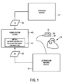
- Fig. 1 illustrates an exemplary embodiment of an ultrasound-image-guided system.
- the system employs an ultrasound imaging system, a tracking system and a computation device 40.
- the ultrasound imaging system is broadly defined herein as any system including one or more ultrasound probes 20 operable or structurally configured to generate image volumes of an anatomical object (e.g., a heart 10) within a coordinate system, and an ultrasound imaging device 21 operable or structurally configured to generate imaging data 22 of the anatomical object based on the image volumes (processing the image volumes).
- each image volume can be a district subset of a baseline image volume of the anatomical object.
- the ultrasound imaging system can particularly use a 3D trans-esophageal echo ("TEE") probe.
- TEEE intelligent echo system commercially sold by Philips Healthcare may serve as an ultrasound imaging system.
- any other suitable ultrasound imaging system can be used.
- the tracking system is broadly defined herein as any system including an adapter device 50 comprising at least one position sensor 30, and a tracking device operable or structurally configured to generate tracking data 32 representative of a tracking of the at least one position sensor 30 within a coordinate system (track position sensor(s) 30 within the coordinate system).
- the adapter device 50 is, for one use event, attachable or attached to one of the ultrasound probes 20.
- a use event refers to the attachment of the adapter device 30 to one of the ultrasound probes and the use of this adapter-probe combination.
- the adapter device 30 is designed such that the at least one position sensor 30 is at a variable position with respect to the one or more ultrasound probes from one use event to another use event.
- the adapter device can be imprecisely manufactured.
- the tracking system include, but are not limited to, any type of electromagnetic tracking system and any type of optical tracking system, for example shape sensing.
- the AuroraTM Electromagnetic Tracking System commercially sold by NDI may serve as an electromagnetic tracking system.
- any other suitable tracking system can be used.
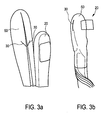
- Fig. 3a illustrates a first embodiment of an adapter device
- Fig. 3b illustrates a second example of an adapter device
- the adapter device 50 is a hard shell having two position sensors 30 integrated therein or attached thereto.
- the position sensors 30 are electromagnetic (EM) sensors.
- the hard shell shown in Fig. 3a is separated into two parts adapted to be clamped against each other. The two parts can be hold apart, placed over the ultrasound probe 20 and then be clamped against each other. In this way, the adapter device fully encloses the ultrasound probe.
- the adapter device 50 and ultrasound probe 20 are adapted for in-vivo application or use.
- the adapter device 50 is an elastic tube.
- the elastic tube is heat shrunk over the sound probe 20.
- computation device 40 is broadly defined herein as any device operable or structurally configured to automatically self-calibrate, for each use event, the imaging data 22 with respect to the coordinate system of the at least one position sensor 30 by calculating a calibration matrix using an image based volume motion and a tracking based volume motion. This can be performed in a calibration unit 41 of the computation device 40, as illustrated in Fig. 1 .
- the computation device 40 can further be operable to register the image volumes to the baseline image volume of the anatomical object 10 (e.g., a full US volume of heart 10).
- a calibration matrix is utilized by computation device 40 as a transformation that converts the coordinates of the voxels in the image volumes in the coordinate system for tracking position sensor 30.
- a calibration matrix represents a spatial relationship between the image volumes and the at least one position sensor 30.
- Fig. 2 illustrates a baseline image volume 12 of an anatomical object (e.g., a full US volume scan of a heart) within a coordinate system 11 (e.g., a tracking coordinate system).
- Ultrasound probe 20 ( Fig. 1 ) is operated to sequentially generate a volume image 13i and a volume image 13j, and position sensor 30 ( Fig. 1 ) is tracked within coordinate system 11 as volume images 13 are generated by probe 20.
- volume images 13 may overlap, but are segregated in Fig. 2 for purposes of clearly showing each individual volume image 13.
- the calibration matrix provides a transformation that converts the coordinates of the voxels in image volumes 13 into coordinate system 11. This enables image volumes 13 to be mapped into the coordinate system for image reconstruction purposes.
- the computation device 40 measures motion 14 between image volumes 13 from two sources.
- the first source being an image motion of image volumes 13, and the second source being a tracking motion of image volumes 13.
- the image volume motion is measured from two sources, (a) image based volume motion and (b) tracking based volume motion.
- the image based volume motion thus, represents an image motion of at least two volumes derived from the imaging system, and the tracking based volume motion represents a tracking motion of the image volumes.
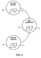
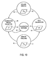
- Fig. 4 illustrates various exemplary operation states of the ultrasound-image-guided system.
- a volume imaging state 60 for generating a number N of image volumes 61 of the anatomical object (e.g., heart 10) via probe 20 ( Fig. 1 ), and a sensor tracking state 70 for a number N of readings of a tracking signal 71 via position sensor 30 ( Fig. 1 ) with each reading of tracking signal 71 corresponding to a generated image volume 61.
- This data is then used in s self-calibration state 50, as shown in Fig. 4 .
- self-calibration state 50 an automatic self calibration, for that use event, of the imaging data 22 with respect to the coordinate system 11 is performed by calculating a calibration matrix 51 using an image based volume motion and a tracking based volume motion.
- the calibration matrix 51 can in particular be an initial calibration matrix.
- the accuracy of calibration matrix 51 is essential for locating each image volume within the coordinate system via tracking signal 71.
- State 50 is implemented by a volume-motion-based calibration method executed by computation device 40, as further explained herein in connection with the description of Figs. 5-9 .
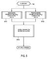
- Fig. 5 illustrates a flowchart 100 representative of one embodiment of the volume-motion-based calibration method.
- a stage S101 of flowchart 100 encompasses a computation by the computation device 40 of an image based volume motion VM IB
- a stage S 102 of flowchart 100 encompasses a computation by the computation device 40 of a tracking based volume motion VM TB .
- image based volume motion VM IB is broadly defined herein as any motion between image volumes 61 ( Fig. 4 ) of the anatomical object within a coordinate system (e.g., coordinate system 11 shown in Fig. 2 ) derived from imaging data 22 ( Fig.
- Stage S103 of flowchart 100 encompasses an initial calibration matrix calculation using the image based volume motion VM IB and to tracking based volume motion VM TB .
- the tracking based volume motion VM TB and the image based volume motion VM IB can be equated using the linear equation, since the amount of motion should be the same.
- the linear equation is solved using a dual quaternion.
- the linear equation can be solved using dual quaternion.
- dual quaternion is for example described in Daniilisdis K, 1999, "Hand-eye calibration using dual quaternion", The Int. J. of Robotics Research, 18(3):286-298 .
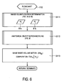
- Fig. 6 illustrates a flowchart 110 representative of an image based volume motion computation method that may be executed during stage S101 ( Fig. 5 ).
- This method involves a processing of pair (i, j) of image volumes (e.g., image volumes 13 shown in Fig. 2 ).
- a stage S111 of flowchart 110 encompasses a determination of a location of an image volume 61a and an image volume 61b within the coordinate system (e.g., coordinate system 11 shown in Fig. 2 )
- a stage S112 of flowchart 110 encompasses a motion compensation of the determined locations of image volumes 61a and 61b in view of a modeling of a motion of the anatomical object (e.g., heart 10).
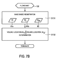
- a flowchart 120 as shown in Fig. 7A includes a stage S121 encompassing an image based registration of the pair (i, j) of image volumes 61a and 61b via a known image based rigid or deformable registration and known optimization metrics (e.g., mutual information, cross correlation, etc.).
- Flowchart 120 further includes a stage S122 encompassing a utilization of the registration of image volumes 61a and 61b to determine a location VL ii of image volume 61a within the coordinate system relative to a location VL ji of image volume 61b within the coordinate system.
- a flowchart 130 as shown in Fig. 7B includes a stage S131 encompassing an image based registration of the pair (i, j) of image volumes 61a and 61b to a baseline image volume 62 of the anatomical object (e.g., a full US image). These registrations may be performed via an image based rigid or deformable registration and known optimization metrics (e.g., mutual information, cross correlation, etc.)
- Flowchart 130 further includes a stage S132 encompassing a utilization of the registration of image volume 61a to baseline image volume 62 to determine location VL ii of image volume 61a relative to baseline image volume 62 within the coordinate system.
- the registration of image volume 61b to baseline image volume 62 is utilized to determine a location VL ji of image volume 61b relative to the baseline image volume 62 within the coordinate system. This facilitates a determination of location VL ii of image volume 61a relative to location VL ji of image volume 61b within the coordinate system.
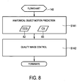
- a flowchart 140 as shown in Fig. 8 includes a stage S141 encompassing a prediction of the motion of anatomical object within the coordinate system.
- a known learning algorithm utilizing an electrocardiogram signal 82 for cardiac phase, a chest belt signal 83 for respiratory phase and any other additional sensing signals to predict the motion of heart 10 within the coordinate system can be used.
- Flowchart 140 further includes a stage S142 encompassing a quality image control involving a motion compensation of image volumes 61a and 61b via the predicted motion of the anatomical object.
- image volumes 61 corresponding to a diastolic phase of heart 10 via ECG signal 82 are exclusively utilized by stage S113 ( Fig. 6 ) for quality control purposes and stage S103 ( Fig. 5 ) will only process the volume motions of these selected image volumes 61. Please note this selection assume respiratory motion is minimal.
- image volumes 61 at time intervals when respiratory phase and cardiac phase come back to the same cycle are exclusively utilized by stage S113 ( Fig. 6 ) for quality control purposes and stage S103 ( Fig. 5 ) will only process the volume motions of these selected image volumes 61.
- a stage S113 of flowchart 110 encompasses a computation of an image based volume motion VM IB as a function of the location VL ii of image volume 61a within the coordinate system relative to the location VL ji of image volume 61b within the coordinate system as known in the art.
- the computed image based volume motion VM IB is implemented by stage S103 ( Fig. 5 ) during the initial calibration matrix calculation.
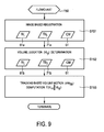
- FIG. 9 illustrates a flowchart 150 representative of a tracking based volume motion computation method that may be executed during stage S102 ( Fig. 5 ).
- a stage S151 of flowchart 150 encompasses a determination of a location VL it of image volume 61a within the coordinate system via a tracking signal 71a and calibration matrix 51 as known in the art. The determined location of VL it of image volume 61a may be confirmed with a location of the baseline image volume of the anatomical object.
- a stage S152 of flowchart 150 encompasses a determination of a location VL jt of image volume 61b within the coordinate system via a tracking signal 71b and calibration matrix 51 as known in the art.
- the determined location of VL jt of image volume 61b may be confirmed with a location of the baseline image volume of the anatomical object.
- a stage S153 of flowchart 150 encompasses a computation of the tracking based volume motion VM TB as a function of location VL it of image volume 61a within the coordinate system relative to a location VL jt of volume 61b within the coordinate system as known in the art.
- a registration transformation between image volumes 61a and 61b based on location VL it of image volume 61a, location VL jt of volume 61b and calibration matrix 51 may be executed as known in the art during stage S153.
- This computed tracking based volume motion VM TB is implemented by stage S103 ( Fig. 5 ) during the initial calibration matrix calculation.
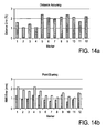
- Fig. 14a and 14b each illustrate results obtained with the ultrasound-image-guided system and/or the volume-motion-based calibration method described above.
- the results of the performance of the calibration were obtained by visual inspection and quantitative validation using a heart simulating object with fiducial markers, simply to test the performance of the system /bmethod. These markers were localized in both a computer tomography image and an ultrasound image and then calibration validation metrics were calculated, including point blowing of single markers over multiple measurements, as shown in Fig. 14b , and distance accuracy of multiple markers, as shown in Fig. 14a .
- the positions of these markers in the computer tomography images were used for the gold standard due to high quality computer tomography images of the hard-simulating object. As can be seen from Fig. 14a and Fig. 14b , the result was that the performance of calibration was very accurate.
- Figs. 10-12 illustrate another (second) embodiment of the system and method in accordance with the present invention.
- the embodiment basically corresponds to the first embodiment described herein above, but in combination with a validity testing of the calibration matrix.
- the calibration matrix calculated by the automatic self-calibration may become inaccurate for a variety of reasons, such as, for example, unexpected field distortions, accidental physical movement of position sensor 30 relative to probe 20 and a partial breakdown of position sensor 30.
- the computation device 40 again measures motion 14 between image volumes 13 from two sources, an image based volume motion and a tracking based volume motion.
- Fig. 10 illustrates the operational states of the ultrasound image-guided system as explained with reference to Fig. 4 . Further, the system moves from self-calibration state 50 to a calibration matrix validation state 80. The accuracy of calibration matrix 51 is essential for locating each image volume 61 within the coordinate system via tracking signal 71. Thus, the calibration validation state 80 utilizes image volumes 61 and tracking signal 71 to ascertain the validity of the calibration matrix. State 80 proceeds to a calibration warning state 90 in view of an invalid calibration matrix. State 80 can be implemented by a calibration matrix validation testing method executed by the computation device 40, as further explained herein in connection with the description of Figs. 11-12 .
- Fig. 11 illustrates a flowchart 200 representative of the second embodiment of the calibration method in accordance with the present invention, in combination with a calibration matrix validation testing method. Steps S101, S102 and S103 correspond to the steps as explained with reference to Fig. 4 . Additionally, a stage S104 of flowchart 200 encompasses another computation by computation device 40 of an image based volume motion VM IB , and a stage S105 of flowchart 100 encompasses another computation by computation device 40 of a tracking based volume motion VM TB .
- Stage S106 of flowchart 100 encompasses a testing of an absolute differential between image based volume motion VM IB and tracking based volume motion VM TB relative to a calibration threshold CT. If the absolute differential is less than calibration threshold CT, then a stage S107 of flowchart 200 encompasses a validation of the calibration matrix that facilitates the continual generation of image volumes 61. Conversely, if the absolute differential is not less than calibration threshold CT, then a stage S108 of flowchart 200 encompasses an invalidation of the calibration matrix that facilitates a warning as to the probable distortion or inaccuracy of image volumes 61.
- stage S107 and S108 real-time calibration alarm is deactivated as the image volumes 61 are being generated with a valid calibration matrix and is activated as a warning to the probable distortion or inaccuracy of image volumes 61 upon an invalidation of the calibration matrix.
- stage S108 a regional map of the anatomical object is displayed as a warning to the probable distortion or inaccuracy of image volumes 61 associated with the regional map.
- a map of the anatomical object may be displayed, whereby region(s) of the map associated with an invalid calibration matrix is (are) distinguished from region(s) of the map associated with a valid calibration matrix as a means for providing a warning of probable distortion or inaccuracy of image volumes 61 associated with the invalid region(s).
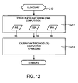
- Fig. 12 illustrates a flowchart 210 representative of a calibration threshold computation method.
- a stage 211 of flowchart 210 encompasses a computation of a possible accuracy margin of the calibration matrix. Random error information 54 can be associated with the tracking system, known statistical accuracy data 55 associated with a pre-operative calibration process, and an image registration accuracy data 56 may be utilized in computing the possible accuracy margin.
- a stage 212 of flowchart 200 encompasses a computation of calibration threshold CL as a function of the computed possible accuracy margin and a desired accuracy margin associated with the application of the system.
- Fig. 13 illustrates an exemplary operation of the ultrasound-image-guided system or the volume-motion-based calibration method in accordance with the present invention in a clinical context.
- the ultrasound probe 20 is provided or manufactured, and the adapter device 50 is provided or manufactured (in particular, the ultrasound probe and adapter device as previously described).
- the surgery is started.
- the adapter device 50 is attached to the ultrasound probe 20.
- the (imprecisely manufactured) adapter device 50 disclosed herein can be (inaccurately) attached to the ultrasound probe 20 just before the surgery.
- This can for example be the hard shell that is clamped on the ultrasound probe and described in connection with Fig. 3a .
- the adapter device/ultrasound probe combination is performed on the patient, thus generating image data and tracking data.
- This data is then used intra-operatively to automatically self-calibrate the system or ultrasound probe with respect to the position sensor.
- This calibrated ultrasound probe with adapter (adapter device-ultrasound probe) is then used for navigation and guidance of a surgical instrument, such as a needle or a catheter for example, during the surgery.
- a surgical instrument such as a needle or a catheter for example
- the calibration matrix can be validated for quality monitoring.
- the adapter device and ultrasound probe are adapted for in-vivo application or use in this case.
- the surgical instrument can be placed inside the ultrasound image/volume.
- the surgical instrument outside of the ultrasound image/volume and can in particular be used for planning and targeting.
- a computer program may be stored/distributed on a suitable medium, such as an optical storage medium or a solid-state medium supplied together with or as part of other hardware, but may also be distributed in other forms, such as via the Internet or other wired or wireless telecommunication systems.
- a suitable medium such as an optical storage medium or a solid-state medium supplied together with or as part of other hardware, but may also be distributed in other forms, such as via the Internet or other wired or wireless telecommunication systems.
Claims (14)
- Système guidé par image ultrasonore, le système comprenant :- une ou plusieurs sondes ultrasonores (20) servant à générer des volumes d'image (13i, 13j) d'un objet anatomique (10) ;- un dispositif adaptateur (50) comprenant au moins un capteur de position (30) ;- un dispositif de localisation (51) servant à générer des données de localisation (32) représentant une localisation du au moins un capteur de position (30) dans un système de coordonnées (11);- un dispositif d'imagerie ultrasonore (21) servant à générer des données d'imagerie (22) de l'objet anatomique (10) sur la base des volumes d'image (13i, 13j) ; et- un dispositif de calcul (40) servant à auto-étalonner automatiquement, pour chaque événement d'utilisation, les données d'imagerie (22) par rapport au système de coordonnées (11) du au moins un capteur de position (30) par le calcul d'une matrice d'étalonnage (51) au moyen d'un mouvement de volume basé sur l'image (VMIB) et d'un mouvement de volume basé sur la localisation (VMTB),le mouvement de volume basé sur l'image (VMIB) représentant un mouvement d'image d'au moins deux volumes d'image (13i, 13j) dérivant des données d'imagerie (22),
le mouvement de volume basé sur la localisation (VMTB) représentant un mouvement de localisation des volumes d'image (13i, 13j) dérivant des données de localisation (32), caractérisé en ce que
le dispositif adaptateur (50) peut être attaché, pour un événement d'utilisation, à l'une des sondes ultrasonores (20), et en ce que
le dispositif de calcul (40) sert en outre à exécuter un test de validation de la matrice d'étalonnage (51) dérivant de l'auto-étalonnage automatique, comprenant un test d'un écart absolu entre le mouvement de volume basé sur l'image (VMIB) et le mouvement de volume basé sur la localisation (VMTB). - Système selon la revendication 1, dans lequel le système est non étalonné avant que le dispositif de calcul (40) auto-étalonne automatiquement les données d'imagerie (22) par rapport au système de coordonnées (11) du au moins un capteur de position (30).
- Système selon la revendication 1, dans lequel le dispositif adaptateur (50) est réutilisable pour une pluralité d'événements d'utilisation.
- Système selon la revendication 1, dans lequel le dispositif adaptateur (50) est une coque dure dans laquelle le au moins un capteur de position (30) est intégré ou à laquelle le au moins un capteur de position est attaché.
- Système selon la revendication 4, dans lequel la coque dure est séparée en au moins deux parties pouvant être fixées les unes aux autres.
- Système selon la revendication 1, dans lequel le dispositif adaptateur (50) est un tube élastique.
- Système selon la revendication 6, dans lequel le tube élastique est thermorétracté sur la sonde ultrasonore.
- Système selon la revendication 1, dans lequel le dispositif adaptateur (50) est un tube inélastique préformé.
- Système selon la revendication 8, dans lequel le tube préformé comporte une couche adhésive interne.
- Système selon la revendication 1, dans lequel le mouvement de volume basé sur l'image (VMIB) est calculé en fonction d'un emplacement d'image (VLii) d'un premier volume d'image (13i) dans le système de coordonnées (11) par rapport à un emplacement d'image (VLji) d'un second volume d'image (13j) dans le système de coordonnées (11) et/ou dans lequel le mouvement de volume basé sur la localisation (VMTB) est calculé en fonction d'un emplacement suivi (VLit) d'un premier volume d'image (13i) dans le système de coordonnées (11) tel que représenté par les données de localisation (32) et d'un emplacement suivi (VLjt) d'un second volume d'image (13j) dans le système de coordonnées (11) tel que représenté par les données de localisation (32).
- Système selon la revendication 1, dans lequel le dispositif de calcul (40) sert à calculer la matrice d'étalonnage par la résolution d'une équation linéaire à l'aide du mouvement de volume basé sur la localisation et du mouvement de volume basé sur l'image.
- Système selon la revendication 1, dans lequel le au moins un capteur de position (30) est un capteur électromagnétique et le dispositif de localisation (51) est un dispositif de localisation électromagnétique.
- Procédé d'étalonnage basé sur un mouvement de volume permettant de faire fonctionner un système guidé par image ultrasonore, le système comprenant une ou plusieurs sondes ultrasonores (20) servant à générer des volumes d'image (13i, 13j) d'un objet anatomique (10), et un dispositif adaptateur (50) comprenant au moins un capteur de position (30), dans lequel le au moins un capteur de position (30) se trouve à une position variable par rapport à la sonde ultrasonore (20) ou aux sondes ultrasonores (20) d'un événement d'utilisation à un autre événement d'utilisation, le procédé comprenant les étapes suivantes :a) la génération de données de localisation (32) représentant une localisation du au moins un capteur de position (30) dans un système de coordonnées (11) ;b) la génération de données d'imagerie (22) de l'objet anatomique (10) sur la base des volumes d'image (13i, 13j) ; etc) l'auto-étalonnage automatique, pour chaque événement d'utilisation, des données d'imagerie (22) par rapport au système de coordonnées (11) du au moins un capteur de position (30) par le calcul d'une matrice d'étalonnage (51) au moyen d'un mouvement de volume basé sur l'image (VMIB) et d'un mouvement de volume basé sur la localisation (VMTB),le mouvement de volume basé sur l'image (VMIB) représentant un mouvement d'image d'au moins deux volumes d'image (13i, 13j) dans le système de coordonnées (11) dérivant des données d'imagerie (22),
le mouvement de volume basé sur la localisation (VMTB) représentant un mouvement de localisation des volumes d'image (13i, 13j) dans le système de coordonnées (11) dérivant des données de localisation (32),
caractérisé en ce que
le dispositif adaptateur (50) peut être attaché, pour un événement d'utilisation, à l'une des sondes ultrasonores (20), et en ce que
le procédé comprend en outre une étape de test de la matrice d'étalonnage (51) dérivant de l'auto-étalonnage automatique, comprenant un test d'un écart absolu entre le mouvement de volume basé sur l'image (VMIB) et le mouvement de volume basé sur la localisation (VMTB). - Programme informatique, comprenant un moyen de code de programme permettant d'amener un ordinateur à mettre en oeuvre les étapes du procédé selon la revendication 13 quand ledit programme informatique est exécuté sur l'ordinateur.
Applications Claiming Priority (2)
| Application Number | Priority Date | Filing Date | Title |
|---|---|---|---|
| US201161501271P | 2011-06-27 | 2011-06-27 | |
| PCT/IB2012/053138 WO2013001424A2 (fr) | 2011-06-27 | 2012-06-21 | Système guidé par image ultrasonore et procédé d'étalonnage à base de mouvement de volume |
Publications (2)
| Publication Number | Publication Date |
|---|---|
| EP2723241A2 EP2723241A2 (fr) | 2014-04-30 |
| EP2723241B1 true EP2723241B1 (fr) | 2014-11-19 |
Family
ID=46579263
Family Applications (1)
| Application Number | Title | Priority Date | Filing Date |
|---|---|---|---|
| EP12738612.6A Not-in-force EP2723241B1 (fr) | 2011-06-27 | 2012-06-21 | Système guidé par image ultrasonore et procédé d'étalonnage à base de mouvement de volume |
Country Status (5)
| Country | Link |
|---|---|
| US (1) | US20140100452A1 (fr) |
| EP (1) | EP2723241B1 (fr) |
| JP (1) | JP6023190B2 (fr) |
| CN (1) | CN103648397B (fr) |
| WO (1) | WO2013001424A2 (fr) |
Families Citing this family (19)
| Publication number | Priority date | Publication date | Assignee | Title |
|---|---|---|---|---|
| EP2584965B1 (fr) * | 2010-06-28 | 2016-04-13 | Koninklijke Philips N.V. | Contrôle de qualité en temps réel d'étalonnage électromagnétique (em) |
| US10743773B2 (en) * | 2012-05-02 | 2020-08-18 | Koninklijke Philips N.V. | Imaging thermometry |
| WO2014111853A2 (fr) * | 2013-01-17 | 2014-07-24 | Koninklijke Philips N.V. | Procédé d'ajustement de zone focale dans une procédure médicale guidée par ultrasons et système employant le procédé |
| JP2014236836A (ja) * | 2013-06-07 | 2014-12-18 | 株式会社東芝 | 超音波診断装置及びそれに用いるアタッチメント |
| JP6434006B2 (ja) * | 2013-06-28 | 2018-12-05 | コーニンクレッカ フィリップス エヌ ヴェKoninklijke Philips N.V. | ハイライトシステム及び判定方法 |
| WO2016088037A1 (fr) * | 2014-12-02 | 2016-06-09 | Koninklijke Philips N.V. | Suivi automatique et enregistrement de sonde ultrasonore à l'aide d'une détection de forme optique sans fixation de pointe |
| EP3277190B1 (fr) * | 2015-03-31 | 2020-08-05 | Koninklijke Philips N.V. | Étalonnage de cartographie de limite de lésion basé sur l'élasticité par ultrasons |
| JP6987040B2 (ja) * | 2015-08-28 | 2021-12-22 | コーニンクレッカ フィリップス エヌ ヴェKoninklijke Philips N.V. | 運動関係を決定する方法及び装置 |
| WO2017046692A1 (fr) * | 2015-09-17 | 2017-03-23 | Koninklijke Philips N.V. | Distinction de glissement de poumon et de mouvement externe |
| KR102530174B1 (ko) | 2016-01-21 | 2023-05-10 | 삼성메디슨 주식회사 | 초음파 영상 장치 및 그 제어 방법 |
| JP2019514476A (ja) * | 2016-04-19 | 2019-06-06 | コーニンクレッカ フィリップス エヌ ヴェKoninklijke Philips N.V. | 超音波イメージングプローブの位置決め |
| CN106204535B (zh) * | 2016-06-24 | 2018-12-11 | 天津清研智束科技有限公司 | 一种高能束斑的标定方法 |
| US20180098816A1 (en) * | 2016-10-06 | 2018-04-12 | Biosense Webster (Israel) Ltd. | Pre-Operative Registration of Anatomical Images with a Position-Tracking System Using Ultrasound |
| CN106725609A (zh) * | 2016-11-18 | 2017-05-31 | 乐普(北京)医疗器械股份有限公司 | 一种弹性检测方法和装置 |
| US11534138B2 (en) * | 2017-09-07 | 2022-12-27 | Piur Imaging Gmbh | Apparatus and method for determining motion of an ultrasound probe |
| CN111655156A (zh) * | 2017-12-19 | 2020-09-11 | 皇家飞利浦有限公司 | 组合基于图像的和惯性探头跟踪 |
| EP3508132A1 (fr) * | 2018-01-04 | 2019-07-10 | Koninklijke Philips N.V. | Système à ultrasons et procédé de correction de désalignement induit par le mouvement de la fusion d'images |
| US11911213B2 (en) * | 2019-06-03 | 2024-02-27 | General Electric Company | Techniques for determining ultrasound probe motion |
| CN113768535A (zh) * | 2021-08-23 | 2021-12-10 | 武汉库柏特科技有限公司 | 一种遥操作用超声仿型探头姿态自校准方法、系统及装置 |
Family Cites Families (18)
| Publication number | Priority date | Publication date | Assignee | Title |
|---|---|---|---|---|
| US5520187A (en) * | 1994-11-25 | 1996-05-28 | General Electric Company | Ultrasonic probe with programmable multiplexer for imaging systems with different channel counts |
| US6975900B2 (en) * | 1997-07-31 | 2005-12-13 | Case Western Reserve University | Systems and methods for determining a surface geometry |
| JP4443672B2 (ja) * | 1998-10-14 | 2010-03-31 | 株式会社東芝 | 超音波診断装置 |
| US6338716B1 (en) * | 1999-11-24 | 2002-01-15 | Acuson Corporation | Medical diagnostic ultrasonic transducer probe and imaging system for use with a position and orientation sensor |
| US7085400B1 (en) * | 2000-06-14 | 2006-08-01 | Surgical Navigation Technologies, Inc. | System and method for image based sensor calibration |
| JP2004065775A (ja) * | 2002-08-08 | 2004-03-04 | Sanwa Kagaku Kenkyusho Co Ltd | 針状構造体を備えたデバイス |
| US20050222793A1 (en) * | 2004-04-02 | 2005-10-06 | Lloyd Charles F | Method and system for calibrating deformed instruments |
| EP2278271B1 (fr) * | 2005-03-11 | 2012-05-23 | Creaform Inc. | Système autoréférencé et scanner optique tridimensionnel |
| US7604601B2 (en) * | 2005-04-26 | 2009-10-20 | Biosense Webster, Inc. | Display of catheter tip with beam direction for ultrasound system |
| CN101695451B (zh) * | 2005-10-04 | 2012-01-18 | 株式会社日立医药 | 超声波诊断装置 |
| US20100190133A1 (en) * | 2007-10-30 | 2010-07-29 | Martinez Daniel L | Irrigation and aspiration device |
| EP2223150A1 (fr) * | 2007-11-14 | 2010-09-01 | Koninklijke Philips Electronics N.V. | Système et procédé pour le calibrage automatique d'ultrason localisé |
| JP5592796B2 (ja) * | 2007-11-14 | 2014-09-17 | コーニンクレッカ フィリップス エヌ ヴェ | 定量3dceus分析のためのシステム及び方法 |
| JP5454844B2 (ja) * | 2008-08-13 | 2014-03-26 | 株式会社東芝 | 超音波診断装置、超音波画像表示装置及び超音波画像表示プログラム |
| US8086298B2 (en) | 2008-09-29 | 2011-12-27 | Civco Medical Instruments Co., Inc. | EM tracking systems for use with ultrasound and other imaging modalities |
| US8690776B2 (en) * | 2009-02-17 | 2014-04-08 | Inneroptic Technology, Inc. | Systems, methods, apparatuses, and computer-readable media for image guided surgery |
| US20110184684A1 (en) * | 2009-07-21 | 2011-07-28 | Eigen, Inc. | 3-d self-correcting freehand ultrasound tracking system |
| EP2584965B1 (fr) * | 2010-06-28 | 2016-04-13 | Koninklijke Philips N.V. | Contrôle de qualité en temps réel d'étalonnage électromagnétique (em) |
-
2012
- 2012-06-21 EP EP12738612.6A patent/EP2723241B1/fr not_active Not-in-force
- 2012-06-21 CN CN201280031580.XA patent/CN103648397B/zh not_active Expired - Fee Related
- 2012-06-21 JP JP2014518004A patent/JP6023190B2/ja not_active Expired - Fee Related
- 2012-06-21 WO PCT/IB2012/053138 patent/WO2013001424A2/fr active Application Filing
- 2012-06-21 US US14/123,786 patent/US20140100452A1/en not_active Abandoned
Also Published As
| Publication number | Publication date |
|---|---|
| JP6023190B2 (ja) | 2016-11-09 |
| EP2723241A2 (fr) | 2014-04-30 |
| CN103648397A (zh) | 2014-03-19 |
| WO2013001424A2 (fr) | 2013-01-03 |
| US20140100452A1 (en) | 2014-04-10 |
| JP2014522683A (ja) | 2014-09-08 |
| CN103648397B (zh) | 2016-01-20 |
| WO2013001424A3 (fr) | 2013-03-07 |
Similar Documents
| Publication | Publication Date | Title |
|---|---|---|
| EP2723241B1 (fr) | Système guidé par image ultrasonore et procédé d'étalonnage à base de mouvement de volume | |
| EP2584965B1 (fr) | Contrôle de qualité en temps réel d'étalonnage électromagnétique (em) | |
| US11033181B2 (en) | System and method for tumor motion simulation and motion compensation using tracked bronchoscopy | |
| EP2800534B1 (fr) | Appareil de détermination de position | |
| US8131031B2 (en) | Systems and methods for inferred patient annotation | |
| US9320569B2 (en) | Systems and methods for implant distance measurement | |
| JP5207795B2 (ja) | 撮像対象中の対象物をナビゲーションするシステム及び方法 | |
| US9265442B2 (en) | Method of calibrating combined field location and MRI tracking | |
| US9572535B2 (en) | Dynamic mapping point filtering using a pre-acquired image | |
| US20120323111A1 (en) | Method and system for characterizing and visualizing electromagnetic tracking errors | |
| US20080119725A1 (en) | Systems and Methods for Visual Verification of CT Registration and Feedback | |
| US20110160569A1 (en) | system and method for real-time surface and volume mapping of anatomical structures | |
| JP6085598B2 (ja) | 画像ガイドインターベンションのための術中画像補正 | |
| JP6779716B2 (ja) | 疑わしいマップシフトの識別及び提示 | |
| CN105491952A (zh) | 探头定位 | |
| CN105873538B (zh) | 用于将成像设备与跟踪设备进行配准的配准系统和方法 | |
| WO2008035271A2 (fr) | Dispositif d'enregistrement d'un modèle 3d | |
| Huang et al. | Image registration based 3D TEE-EM calibration |
Legal Events
| Date | Code | Title | Description |
|---|---|---|---|
| PUAI | Public reference made under article 153(3) epc to a published international application that has entered the european phase |
Free format text: ORIGINAL CODE: 0009012 |
|
| 17P | Request for examination filed |
Effective date: 20140127 |
|
| AK | Designated contracting states |
Kind code of ref document: A2 Designated state(s): AL AT BE BG CH CY CZ DE DK EE ES FI FR GB GR HR HU IE IS IT LI LT LU LV MC MK MT NL NO PL PT RO RS SE SI SK SM TR |
|
| GRAP | Despatch of communication of intention to grant a patent |
Free format text: ORIGINAL CODE: EPIDOSNIGR1 |
|
| DAX | Request for extension of the european patent (deleted) | ||
| INTG | Intention to grant announced |
Effective date: 20140620 |
|
| GRAS | Grant fee paid |
Free format text: ORIGINAL CODE: EPIDOSNIGR3 |
|
| GRAA | (expected) grant |
Free format text: ORIGINAL CODE: 0009210 |
|
| AK | Designated contracting states |
Kind code of ref document: B1 Designated state(s): AL AT BE BG CH CY CZ DE DK EE ES FI FR GB GR HR HU IE IS IT LI LT LU LV MC MK MT NL NO PL PT RO RS SE SI SK SM TR |
|
| REG | Reference to a national code |
Ref country code: GB Ref legal event code: FG4D |
|
| REG | Reference to a national code |
Ref country code: CH Ref legal event code: EP |
|
| REG | Reference to a national code |
Ref country code: AT Ref legal event code: REF Ref document number: 696526 Country of ref document: AT Kind code of ref document: T Effective date: 20141215 |
|
| REG | Reference to a national code |
Ref country code: IE Ref legal event code: FG4D |
|
| REG | Reference to a national code |
Ref country code: DE Ref legal event code: R096 Ref document number: 602012003911 Country of ref document: DE Effective date: 20141231 |
|
| REG | Reference to a national code |
Ref country code: NL Ref legal event code: VDEP Effective date: 20141119 |
|
| REG | Reference to a national code |
Ref country code: AT Ref legal event code: MK05 Ref document number: 696526 Country of ref document: AT Kind code of ref document: T Effective date: 20141119 |
|
| REG | Reference to a national code |
Ref country code: LT Ref legal event code: MG4D |
|
| PG25 | Lapsed in a contracting state [announced via postgrant information from national office to epo] |
Ref country code: IS Free format text: LAPSE BECAUSE OF FAILURE TO SUBMIT A TRANSLATION OF THE DESCRIPTION OR TO PAY THE FEE WITHIN THE PRESCRIBED TIME-LIMIT Effective date: 20150319 Ref country code: NO Free format text: LAPSE BECAUSE OF FAILURE TO SUBMIT A TRANSLATION OF THE DESCRIPTION OR TO PAY THE FEE WITHIN THE PRESCRIBED TIME-LIMIT Effective date: 20150219 Ref country code: ES Free format text: LAPSE BECAUSE OF FAILURE TO SUBMIT A TRANSLATION OF THE DESCRIPTION OR TO PAY THE FEE WITHIN THE PRESCRIBED TIME-LIMIT Effective date: 20141119 Ref country code: PT Free format text: LAPSE BECAUSE OF FAILURE TO SUBMIT A TRANSLATION OF THE DESCRIPTION OR TO PAY THE FEE WITHIN THE PRESCRIBED TIME-LIMIT Effective date: 20150319 Ref country code: LT Free format text: LAPSE BECAUSE OF FAILURE TO SUBMIT A TRANSLATION OF THE DESCRIPTION OR TO PAY THE FEE WITHIN THE PRESCRIBED TIME-LIMIT Effective date: 20141119 Ref country code: FI Free format text: LAPSE BECAUSE OF FAILURE TO SUBMIT A TRANSLATION OF THE DESCRIPTION OR TO PAY THE FEE WITHIN THE PRESCRIBED TIME-LIMIT Effective date: 20141119 Ref country code: NL Free format text: LAPSE BECAUSE OF FAILURE TO SUBMIT A TRANSLATION OF THE DESCRIPTION OR TO PAY THE FEE WITHIN THE PRESCRIBED TIME-LIMIT Effective date: 20141119 |
|
| PG25 | Lapsed in a contracting state [announced via postgrant information from national office to epo] |
Ref country code: SE Free format text: LAPSE BECAUSE OF FAILURE TO SUBMIT A TRANSLATION OF THE DESCRIPTION OR TO PAY THE FEE WITHIN THE PRESCRIBED TIME-LIMIT Effective date: 20141119 Ref country code: GR Free format text: LAPSE BECAUSE OF FAILURE TO SUBMIT A TRANSLATION OF THE DESCRIPTION OR TO PAY THE FEE WITHIN THE PRESCRIBED TIME-LIMIT Effective date: 20150220 Ref country code: HR Free format text: LAPSE BECAUSE OF FAILURE TO SUBMIT A TRANSLATION OF THE DESCRIPTION OR TO PAY THE FEE WITHIN THE PRESCRIBED TIME-LIMIT Effective date: 20141119 Ref country code: CY Free format text: LAPSE BECAUSE OF FAILURE TO SUBMIT A TRANSLATION OF THE DESCRIPTION OR TO PAY THE FEE WITHIN THE PRESCRIBED TIME-LIMIT Effective date: 20141119 Ref country code: AT Free format text: LAPSE BECAUSE OF FAILURE TO SUBMIT A TRANSLATION OF THE DESCRIPTION OR TO PAY THE FEE WITHIN THE PRESCRIBED TIME-LIMIT Effective date: 20141119 Ref country code: RS Free format text: LAPSE BECAUSE OF FAILURE TO SUBMIT A TRANSLATION OF THE DESCRIPTION OR TO PAY THE FEE WITHIN THE PRESCRIBED TIME-LIMIT Effective date: 20141119 Ref country code: LV Free format text: LAPSE BECAUSE OF FAILURE TO SUBMIT A TRANSLATION OF THE DESCRIPTION OR TO PAY THE FEE WITHIN THE PRESCRIBED TIME-LIMIT Effective date: 20141119 Ref country code: PL Free format text: LAPSE BECAUSE OF FAILURE TO SUBMIT A TRANSLATION OF THE DESCRIPTION OR TO PAY THE FEE WITHIN THE PRESCRIBED TIME-LIMIT Effective date: 20141119 |
|
| PG25 | Lapsed in a contracting state [announced via postgrant information from national office to epo] |
Ref country code: EE Free format text: LAPSE BECAUSE OF FAILURE TO SUBMIT A TRANSLATION OF THE DESCRIPTION OR TO PAY THE FEE WITHIN THE PRESCRIBED TIME-LIMIT Effective date: 20141119 Ref country code: DK Free format text: LAPSE BECAUSE OF FAILURE TO SUBMIT A TRANSLATION OF THE DESCRIPTION OR TO PAY THE FEE WITHIN THE PRESCRIBED TIME-LIMIT Effective date: 20141119 Ref country code: CZ Free format text: LAPSE BECAUSE OF FAILURE TO SUBMIT A TRANSLATION OF THE DESCRIPTION OR TO PAY THE FEE WITHIN THE PRESCRIBED TIME-LIMIT Effective date: 20141119 Ref country code: RO Free format text: LAPSE BECAUSE OF FAILURE TO SUBMIT A TRANSLATION OF THE DESCRIPTION OR TO PAY THE FEE WITHIN THE PRESCRIBED TIME-LIMIT Effective date: 20141119 Ref country code: SK Free format text: LAPSE BECAUSE OF FAILURE TO SUBMIT A TRANSLATION OF THE DESCRIPTION OR TO PAY THE FEE WITHIN THE PRESCRIBED TIME-LIMIT Effective date: 20141119 |
|
| REG | Reference to a national code |
Ref country code: DE Ref legal event code: R097 Ref document number: 602012003911 Country of ref document: DE |
|
| PLBE | No opposition filed within time limit |
Free format text: ORIGINAL CODE: 0009261 |
|
| STAA | Information on the status of an ep patent application or granted ep patent |
Free format text: STATUS: NO OPPOSITION FILED WITHIN TIME LIMIT |
|
| 26N | No opposition filed |
Effective date: 20150820 |
|
| PG25 | Lapsed in a contracting state [announced via postgrant information from national office to epo] |
Ref country code: IT Free format text: LAPSE BECAUSE OF FAILURE TO SUBMIT A TRANSLATION OF THE DESCRIPTION OR TO PAY THE FEE WITHIN THE PRESCRIBED TIME-LIMIT Effective date: 20141119 |
|
| PG25 | Lapsed in a contracting state [announced via postgrant information from national office to epo] |
Ref country code: MC Free format text: LAPSE BECAUSE OF FAILURE TO SUBMIT A TRANSLATION OF THE DESCRIPTION OR TO PAY THE FEE WITHIN THE PRESCRIBED TIME-LIMIT Effective date: 20141119 |
|
| REG | Reference to a national code |
Ref country code: CH Ref legal event code: PL |
|
| PG25 | Lapsed in a contracting state [announced via postgrant information from national office to epo] |
Ref country code: SI Free format text: LAPSE BECAUSE OF FAILURE TO SUBMIT A TRANSLATION OF THE DESCRIPTION OR TO PAY THE FEE WITHIN THE PRESCRIBED TIME-LIMIT Effective date: 20141119 Ref country code: LU Free format text: LAPSE BECAUSE OF FAILURE TO SUBMIT A TRANSLATION OF THE DESCRIPTION OR TO PAY THE FEE WITHIN THE PRESCRIBED TIME-LIMIT Effective date: 20150621 |
|
| REG | Reference to a national code |
Ref country code: IE Ref legal event code: MM4A |
|
| REG | Reference to a national code |
Ref country code: FR Ref legal event code: ST Effective date: 20160229 |
|
| PG25 | Lapsed in a contracting state [announced via postgrant information from national office to epo] |
Ref country code: CH Free format text: LAPSE BECAUSE OF NON-PAYMENT OF DUE FEES Effective date: 20150630 Ref country code: IE Free format text: LAPSE BECAUSE OF NON-PAYMENT OF DUE FEES Effective date: 20150621 Ref country code: LI Free format text: LAPSE BECAUSE OF NON-PAYMENT OF DUE FEES Effective date: 20150630 |
|
| PG25 | Lapsed in a contracting state [announced via postgrant information from national office to epo] |
Ref country code: FR Free format text: LAPSE BECAUSE OF NON-PAYMENT OF DUE FEES Effective date: 20150630 |
|
| PG25 | Lapsed in a contracting state [announced via postgrant information from national office to epo] |
Ref country code: MT Free format text: LAPSE BECAUSE OF FAILURE TO SUBMIT A TRANSLATION OF THE DESCRIPTION OR TO PAY THE FEE WITHIN THE PRESCRIBED TIME-LIMIT Effective date: 20141119 |
|
| GBPC | Gb: european patent ceased through non-payment of renewal fee |
Effective date: 20160621 |
|
| PG25 | Lapsed in a contracting state [announced via postgrant information from national office to epo] |
Ref country code: BG Free format text: LAPSE BECAUSE OF FAILURE TO SUBMIT A TRANSLATION OF THE DESCRIPTION OR TO PAY THE FEE WITHIN THE PRESCRIBED TIME-LIMIT Effective date: 20141119 Ref country code: GB Free format text: LAPSE BECAUSE OF NON-PAYMENT OF DUE FEES Effective date: 20160621 Ref country code: HU Free format text: LAPSE BECAUSE OF FAILURE TO SUBMIT A TRANSLATION OF THE DESCRIPTION OR TO PAY THE FEE WITHIN THE PRESCRIBED TIME-LIMIT; INVALID AB INITIO Effective date: 20120621 Ref country code: SM Free format text: LAPSE BECAUSE OF FAILURE TO SUBMIT A TRANSLATION OF THE DESCRIPTION OR TO PAY THE FEE WITHIN THE PRESCRIBED TIME-LIMIT Effective date: 20141119 |
|
| PG25 | Lapsed in a contracting state [announced via postgrant information from national office to epo] |
Ref country code: TR Free format text: LAPSE BECAUSE OF FAILURE TO SUBMIT A TRANSLATION OF THE DESCRIPTION OR TO PAY THE FEE WITHIN THE PRESCRIBED TIME-LIMIT Effective date: 20141119 |
|
| PG25 | Lapsed in a contracting state [announced via postgrant information from national office to epo] |
Ref country code: BE Free format text: LAPSE BECAUSE OF FAILURE TO SUBMIT A TRANSLATION OF THE DESCRIPTION OR TO PAY THE FEE WITHIN THE PRESCRIBED TIME-LIMIT Effective date: 20141119 |
|
| PG25 | Lapsed in a contracting state [announced via postgrant information from national office to epo] |
Ref country code: MK Free format text: LAPSE BECAUSE OF FAILURE TO SUBMIT A TRANSLATION OF THE DESCRIPTION OR TO PAY THE FEE WITHIN THE PRESCRIBED TIME-LIMIT Effective date: 20141119 |
|
| PG25 | Lapsed in a contracting state [announced via postgrant information from national office to epo] |
Ref country code: AL Free format text: LAPSE BECAUSE OF FAILURE TO SUBMIT A TRANSLATION OF THE DESCRIPTION OR TO PAY THE FEE WITHIN THE PRESCRIBED TIME-LIMIT Effective date: 20141119 |
|
| PGFP | Annual fee paid to national office [announced via postgrant information from national office to epo] |
Ref country code: DE Payment date: 20180831 Year of fee payment: 7 |
|
| REG | Reference to a national code |
Ref country code: DE Ref legal event code: R119 Ref document number: 602012003911 Country of ref document: DE |
|
| PG25 | Lapsed in a contracting state [announced via postgrant information from national office to epo] |
Ref country code: DE Free format text: LAPSE BECAUSE OF NON-PAYMENT OF DUE FEES Effective date: 20200101 |