EP2722519B1 - Startvorrichtung für eine Brennkraftmaschine - Google Patents
Startvorrichtung für eine Brennkraftmaschine Download PDFInfo
- Publication number
- EP2722519B1 EP2722519B1 EP13183672.8A EP13183672A EP2722519B1 EP 2722519 B1 EP2722519 B1 EP 2722519B1 EP 13183672 A EP13183672 A EP 13183672A EP 2722519 B1 EP2722519 B1 EP 2722519B1
- Authority
- EP
- European Patent Office
- Prior art keywords
- transmission component
- starting device
- damping elements
- starter
- transmission
- Prior art date
- Legal status (The legal status is an assumption and is not a legal conclusion. Google has not performed a legal analysis and makes no representation as to the accuracy of the status listed.)
- Not-in-force
Links
Images

Classifications
-
- F—MECHANICAL ENGINEERING; LIGHTING; HEATING; WEAPONS; BLASTING
- F02—COMBUSTION ENGINES; HOT-GAS OR COMBUSTION-PRODUCT ENGINE PLANTS
- F02N—STARTING OF COMBUSTION ENGINES; STARTING AIDS FOR SUCH ENGINES, NOT OTHERWISE PROVIDED FOR
- F02N15/00—Other power-operated starting apparatus; Component parts, details, or accessories, not provided for in, or of interest apart from groups F02N5/00 - F02N13/00
- F02N15/02—Gearing between starting-engines and started engines; Engagement or disengagement thereof
- F02N15/04—Gearing between starting-engines and started engines; Engagement or disengagement thereof the gearing including disengaging toothed gears
- F02N15/043—Gearing between starting-engines and started engines; Engagement or disengagement thereof the gearing including disengaging toothed gears the gearing including a speed reducer
- F02N15/046—Gearing between starting-engines and started engines; Engagement or disengagement thereof the gearing including disengaging toothed gears the gearing including a speed reducer of the planetary type
-
- F—MECHANICAL ENGINEERING; LIGHTING; HEATING; WEAPONS; BLASTING
- F02—COMBUSTION ENGINES; HOT-GAS OR COMBUSTION-PRODUCT ENGINE PLANTS
- F02N—STARTING OF COMBUSTION ENGINES; STARTING AIDS FOR SUCH ENGINES, NOT OTHERWISE PROVIDED FOR
- F02N11/00—Starting of engines by means of electric motors
-
- F—MECHANICAL ENGINEERING; LIGHTING; HEATING; WEAPONS; BLASTING
- F02—COMBUSTION ENGINES; HOT-GAS OR COMBUSTION-PRODUCT ENGINE PLANTS
- F02N—STARTING OF COMBUSTION ENGINES; STARTING AIDS FOR SUCH ENGINES, NOT OTHERWISE PROVIDED FOR
- F02N15/00—Other power-operated starting apparatus; Component parts, details, or accessories, not provided for in, or of interest apart from groups F02N5/00 - F02N13/00
- F02N15/02—Gearing between starting-engines and started engines; Engagement or disengagement thereof
- F02N15/04—Gearing between starting-engines and started engines; Engagement or disengagement thereof the gearing including disengaging toothed gears
- F02N15/06—Gearing between starting-engines and started engines; Engagement or disengagement thereof the gearing including disengaging toothed gears the toothed gears being moved by axial displacement
- F02N15/062—Starter drives
- F02N15/063—Starter drives with resilient shock absorbers
-
- F—MECHANICAL ENGINEERING; LIGHTING; HEATING; WEAPONS; BLASTING
- F02—COMBUSTION ENGINES; HOT-GAS OR COMBUSTION-PRODUCT ENGINE PLANTS
- F02N—STARTING OF COMBUSTION ENGINES; STARTING AIDS FOR SUCH ENGINES, NOT OTHERWISE PROVIDED FOR
- F02N15/00—Other power-operated starting apparatus; Component parts, details, or accessories, not provided for in, or of interest apart from groups F02N5/00 - F02N13/00
- F02N15/02—Gearing between starting-engines and started engines; Engagement or disengagement thereof
- F02N15/04—Gearing between starting-engines and started engines; Engagement or disengagement thereof the gearing including disengaging toothed gears
- F02N15/06—Gearing between starting-engines and started engines; Engagement or disengagement thereof the gearing including disengaging toothed gears the toothed gears being moved by axial displacement
- F02N15/067—Gearing between starting-engines and started engines; Engagement or disengagement thereof the gearing including disengaging toothed gears the toothed gears being moved by axial displacement the starter comprising an electro-magnetically actuated lever
Definitions
- the invention relates to a starting device for an internal combustion engine according to the preamble of claim 1.
- the transmission components such as a ring gear of the planetary gear subject in operation jerky torque loads.
- To reduce the load is in accordance with the EP 1 347 171 A1 provided to support the ring gear of the planetary gear via a damping ring on the gear housing.
- On the damping ring form-fitting elements are arranged, which engage positively in corresponding receiving parts on the transmission housing. The damping takes place in the circumferential direction and in the axial direction.
- a starter in which a ring gear is supported as a on a side facing away from the engine by means of damping elements and a friction ring on a transmission housing.
- WO 2010/034829 discloses another starter in which damping elements are used.
- the invention is based on the object to reduce the mechanical load in the drive train of a starting device for an internal combustion engine with simple constructive measures.
- the starting device according to the invention which is used for starting internal combustion engines, has a starter pinion, which is adjustable between a retracted non-functional position and a pre-loaded engagement position with a ring gear of the internal combustion engine.
- the adjusting movement of the starter pinion is advantageously carried out by means of a starter relay, in particular an electromagnetic starter relay whose lifting armature movement can be transmitted directly or indirectly to the starter pinion via a transmission component, for example a fork lever.
- the adjusting movement of the starter pinion between the non-functional and the engaged position is preferably an axial adjusting movement.
- the rotational movement of the starter pinion is generated by an electric starter motor, which is followed by a gear for speed reduction, which is the output side connected to the starter pinion.
- a transmission component is supported on both axial end faces via damping elements in the circumferential direction relative to adjacent components of the transmission or of the starter motor. The relevant transmission component receives during a rotational movement of the starter motor torques which are supported via the damping elements on the adjoining components.
- the damping elements are located on both axial end faces and lie directly against the respective end face of the transmission component, so that the transmission component is fully supported in the circumferential or rotational direction via the damping elements and accordingly takes place in the circumferential direction damping or capping of torque peaks, so that also the adjacent components, which absorb the torque, are subject to a correspondingly lower load.
- Another aspect of the invention also relates to a starting device with an electric motor driven starter pinion, which between a non-functional position and an engagement position with a ring gear of the Internal combustion engine is adjustable.
- the electric starter motor is followed by a transmission for speed reduction, wherein at least one damping element is arranged on at least one axial end side of a transmission component.
- the damping element is supported at least in the circumferential direction on the motor side on the pole housing of the electric starter motor.
- the pole housing thus absorbs moments in the rotational or circumferential direction, wherein torque peaks are reduced due to the storage in the circumferential direction over the or the damping elements.
- the transmission component is supported via the arranged on both axial end faces damping elements in the axial direction of the adjacent components.
- a floating mounting of the transmission component is achieved in the axial direction and in the circumferential or rotational direction.
- a plurality of damping elements are arranged on at least one end face of the transmission component, but preferably on both end faces of the transmission component distributed over the circumference.
- the damping elements on the opposite end faces can either have the same structure or differ in one parameter, for example with regard to the size, the geometry and / or the damping.
- the damping elements are preferably made of an elastomer and are designed for example as an elastomer block.
- the transmission component is expediently dimensioned slightly smaller relative to the available installation space, so that the support is ensured exclusively by damping elements ,
- the transmission component For the damping in rotational or circumferential direction, it may be appropriate to arrange on at least one end face of the transmission component one or more axially projecting support members on which at least one damping element is supported in the circumferential direction.
- axially projecting support members At arranged on both end faces of the transmission component such axially projecting support members.
- the damping elements can be supported on one side of the transmission component on a motor bearing plate, which in turn is supported on the pole housing of the starter motor.
- the engine mount plate can be firmly connected to the pole housing, but be designed as a separate component.
- an intermediate bearing part which also represents a component of the transmission.
- the facing damping elements of the transmission component are supported in the circumferential direction and optionally in the axial direction.
- the intermediate bearing part can be connected to the pole housing of the electric starter motor, in particular such that the intermediate bearing part is centered in the pole housing and thus the rotational position of the intermediate bearing part is aligned on the pole housing.
- the transmission is, according to a further advantageous embodiment, a planetary gear, and in the axially frontally supported via damping elements gear member to a ring gear of the planetary gear, in which the planetary gears roll in operation.
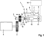
- starting device 1 for an internal combustion engine has a starter pinion 2, which is brought to start the internal combustion engine 4 in engagement with a ring gear 3 of the internal combustion engine.
- the starter pinion 2 is mounted axially displaceably on a shaft 5 as indicated by the double arrow, wherein the starter pinion 2 is non-rotatably coupled to the shaft 5.
- the starter pinion 2 is moved between a retracted non-functional position and an advanced engagement position with the ring gear 3 of the internal combustion engine 4 via a starter relay 6, which is electromagnetically designed and a Bestrombare relay winding 7 and a lifting armature 8, which pulled in energizing the relay coil 7 in this axially becomes.
- the lifting armature 8 is kinematically coupled to the starter pinion 2 via an engaging lever 9, so that the axial adjusting movement of the lifting armature 8 between a rest position and an adjusting position is inserted into a corresponding axial adjusting movement of the starter pinion 2 between the non-functional position and the engaged position.
- the rotating drive movement on the shaft 5 or the starter pinion 2 is generated by means of an electric starter motor 11, which is coupled via a planetary gear 12 with the shaft 5.
- an electric starter motor 11 which is coupled via a planetary gear 12 with the shaft 5.
- the starting device 1 is associated with a control or control device 10, via which the functions of the starter relay 6 and the starter motor 11 are controlled.
- the starting device 1 is provided with a freewheel device, which is designed as a roller freewheel 14.
- the engagement lever 9 acts on a spring element 13, the force is applied axially to a driver 15 of the roller freewheel 14, wherein with the driver 15, a support or roller collar 16 of the roller freewheel 14 cooperates and the support collar 16 is formed integrally with the starter pinion 2.
- the rotational speed of the ring gear 3 is so high that the drive direction is reversed, via the roller freewheel 14, the kinematic coupling between driver 15 and Support collar 16 repealed.
- the planetary gear 12 is shown, via which the drive movement of the electric starter motor is transmitted to the starter pinion.
- the planetary gear 12 connects axially to a pole housing 17 of the starter motor and is partially overlapped by the pole housing 17.
- Part of the planetary gear 12 is a ring gear 18, which has an internal toothing and rotate in the planetary gears of the planetary gear.
- a drive movement through the starter motor act on the ring gear forces or moments in the circumferential or rotational direction, which are absorbed by the adjacent components.
- damping elements 19 are arranged, via which the ring gear 18 is supported in the direction of rotation on the motor side via a motor bearing plate 20 on the pole housing 17 and on the opposite side to an intermediate bearing part 21.
- the motor bearing plate 20 is fixedly connected in the direction of rotation with the pole housing 17, in the axial direction, the motor bearing plate 20 is held with play on the pole housing 17.
- the damping elements 19 on the two end faces of the ring gear 18 also supported the ring gear axially against both the motor bearing plate 20 and the pole housing 17 and against the intermediate bearing part 21 from.
- the ring gear 18 is floatingly mounted, so that the ring gear 18 is exclusively on the damping elements 19 in contact with surrounding components. In target or standard position of the ring gear 18, there is no direct contact in the axial direction or radial direction to the surrounding components.
- the damping elements 19 are arranged angularly offset at the opposite end faces of the ring gear 18.
- peg-shaped support members 22 are formed on which the damping elements 19 are supported at a load in the direction of rotation.
- the Support members 22 may optionally also serve to receive and support the damping elements 19.
- the pole housing 17 projects beyond the ring gear 18 in the axial direction and extends to the intermediate bearing part 21, which is centered on the pole housing 17.
Landscapes
- Engineering & Computer Science (AREA)
- Chemical & Material Sciences (AREA)
- Combustion & Propulsion (AREA)
- Mechanical Engineering (AREA)
- General Engineering & Computer Science (AREA)
- Connection Of Motors, Electrical Generators, Mechanical Devices, And The Like (AREA)
Description
- Die Erfindung bezieht sich auf eine Startvorrichtung für eine Brennkraftmaschine nach dem Oberbegriff des Anspruches 1.
- Bekannt sind Startvorrichtungen für Brennkraftmaschinen, beispielsweise aus der
DE 10 2007 026 078 A1 , die ein von einem elektrischen Startermotor drehend antreibbares Starterritzel aufweisen, welches axial zwischen einer Außerfunktionsposition und einer Eingriffsposition mit einem Zahnkranz der zu startenden Brennkraftmaschine zu verstellen ist. Die axiale Stellbewegung wird mithilfe eines elektromagnetischen Starterrelais durchgeführt. Die Antriebsbewegung des elektrischen Startermotors wird über ein Planetengetriebe auf das Starterritzel übertragen. - Die Getriebebauteile wie z.B. ein Hohlrad des Planetengetriebes unterliegen im Betrieb stoßartigen Drehmomentbelastungen. Zur Reduzierung der Belastung ist gemäß der
EP 1 347 171 A1 vorgesehen, das Hohlrad des Planetengetriebes über einen Dämpfungsring am Getriebegehäuse abzustützen. Am Dämpfungsring sind Formschlusselemente angeordnet, die in korrespondierende Aufnahmeteile am Getriebegehäuse formschlüssig angreifen. Die Dämpfung erfolgt in Umfangsrichtung und in Achsrichtung. - Aus der
EP 0 529 456 A1 ist ein Starter bekannt, bei dem ein Hohlrad als ein auf einer dem Motor abgewandten Seite mittels Dämpfungselementen und einem Reibring an einem Getriebegehäuse abgestützt ist. -
WO 2010/034829 offenbart einen weiteren Starter bei dem Dämpfungselemente verwendet werden. - Der Erfindung liegt die Aufgabe zu Grunde, mit einfachen konstruktiven Maßnahmen die mechanische Belastung im Antriebsstrang einer Startvorrichtung für eine Brennkraftmaschine zu reduzieren.
- Diese Aufgabe wird erfindungsgemäß mit den Merkmalen der unabhängigen Ansprüche gelöst. Die Unteransprüche geben zweckmäßige Weiterbildungen an.
- Die erfindungsgemäße Startvorrichtung, welche zum Starten von Brennkraftmaschinen eingesetzt wird, weist ein Starterritzel auf, das zwischen einer zurückgezogenen Außerfunktionsstellung und einer vorgespurten Eingriffsposition mit einem Zahnkranz der Brennkraftmaschine verstellbar ist. Die Verstellbewegung des Starterritzels wird vorteilhafterweise mittels eines Starterrelais, insbesondere eines elektromagnetischen Starterrelais durchgeführt, dessen Hubankerbewegung über ein Übertragungsbauteil, beispielsweise einen Gabelhebel, direkt oder indirekt auf das Starterritzel übertragbar ist. Bei der Verstellbewegung des Starterritzels zwischen der Außerfunktions- und der Eingriffsposition handelt es sich vorzugsweise um eine axiale Stellbewegung.
- Die Drehbewegung des Starterritzels wird über einen elektrischen Startermotor erzeugt, dem zur Drehzahluntersetzung ein Getriebe nachgeschaltet ist, welches ausgangsseitig mit dem Starterritzel verbunden ist. Ein Getriebebauteil ist an beiden axialen Stirnseiten über Dämpfungselemente in Umfangsrichtung gegenüber benachbarten Bauteilen des Getriebes bzw. des Startermotors abgestützt. Das betreffende Getriebebauteil nimmt bei einer Rotationsbewegung des Startermotors Drehmomente auf, die über die Dämpfungselemente an den sich anschließenden Bauteilen abgestützt werden. Die Dämpfungselemente befinden sich an beiden axialen Stirnseiten und liegen unmittelbar an der jeweiligen Stirnseite des Getriebebauteils an, so dass in Umfangs- bzw. Drehrichtung das Getriebebauteil vollständig über die Dämpfungselemente abgestützt ist und dementsprechend in Umfangsrichtung eine Dämpfung bzw. Kappung von Drehmomentspitzen erfolgt, so dass auch die angrenzenden Bauteile, welche das Drehmoment aufnehmen, einer entsprechend geringeren Belastung unterliegen.
- Ein weiterer Aspekt der Erfindung bezieht sich ebenfalls auf eine Startvorrichtung mit einem elektromotorisch angetriebenen Starterritzel, welches zwischen einer Außerfunktionsposition und einer Eingriffsposition mit einem Zahnkranz der Brennkraftmaschine verstellbar ist. Dem elektrischen Startermotor ist ein Getriebe zur Drehzahluntersetzung nachgeschaltet, wobei mindestens ein Dämpfungselement an zumindest einer axialen Stirnseite eines Getriebebauteils angeordnet ist. Das Dämpfungselement stützt sich zumindest in Umfangsrichtung auf der Motorseite an dem Polgehäuse des elektrischen Startermotors ab. Das Polgehäuse nimmt somit Momente in Dreh- bzw. Umfangsrichtung auf, wobei Drehmomentspitzen auf Grund der Lagerung in Umfangsrichtung über das bzw. die Dämpfungselemente reduziert sind.
- Gemäß einer vorteilhaften Ausführung ist vorgesehen, dass das Getriebebauteil über die an beiden axialen Stirnseiten angeordneten Dämpfungselemente auch in Achsrichtung an den angrenzenden Bauteilen abgestützt ist. Hierdurch wird in Achsrichtung und in Umfangs- bzw. Drehrichtung eine schwimmende Lagerung des Getriebebauteils erreicht.
- Gemäß einer weiteren zweckmäßigen Ausführung sind an mindestens einer Stirnseite des Getriebebauteils, vorzugsweise jedoch an beiden Stirnseiten des Getriebebauteils über den Umfang verteilt mehrere Dämpfungselemente angeordnet. Die Dämpfungselemente an den gegenüberliegenden Stirnseiten können entweder gleich aufgebaut sein oder sich in einem Parameter unterscheiden, beispielsweise im Hinblick auf die Größe, die Geometrie und/oder die Dämpfung. Die Dämpfungselemente bestehen vorzugsweise aus einem Elastomer und sind beispielsweise als Elastomerblock ausgeführt. Um im Soll- bzw. Normzustand einen direkten Kontakt zwischen dem Getriebebauteil und angrenzenden weiteren Bauteilen des Startermotors bzw. des Getriebes zu vermeiden, wird das Getriebebauteil zweckmäßigerweise bezogen auf den zur Verfügung stehenden Einbauraum geringfügig kleiner dimensioniert, so dass die Abstützung ausschließlich über Dämpfungselemente gewährleistet ist.
- Für die Dämpfung in Dreh- bzw. Umfangsrichtung kann es zweckmäßig sein, an mindestens einer Stirnseite des Getriebebauteils ein oder mehrere axial überstehende Stützglieder anzuordnen, an dem sich zumindest ein Dämpfungselement in Umfangsrichtung abstützt. Vorteilhafterweise sind an beiden Stirnseiten des Getriebebauteils derartige axial überstehende Stützglieder angeordnet. Bei einer Drehmomentbeaufschlagung versucht sich das Getriebebauteil zu verdrehen; die hierbei auftretenden Momente werden über die axialen Stützglieder auf die Dämpfungselemente und von diesen weiter auf die benachbarten Bauteile übertragen.
- Die Dämpfungselemente können sich an einer Seite des Getriebebauteils auf einer Motorlagerplatte abstützen, die sich ihrerseits an dem Polgehäuse des Startermotors abstützt. Die Motorlagerplatte kann fest mit dem Polgehäuse verbunden sein, jedoch als separates Bauteil ausgebildet sein.
- Auf der der Motorplatte gegenüberliegenden Seite befindet sich zweckmäßig ein Zwischenlagerteil, welches ebenfalls ein Bauteil des Getriebes darstellt. An dem Zwischenlagerteil stützen sich die zugewandten Dämpfungselemente des Getriebebauteils in Umfangsrichtung und ggf. in Achsrichtung ab. Das Zwischenlagerteil kann mit dem Polgehäuse des elektrischen Startermotors verbunden sein, insbesondere derart, dass das Zwischenlagerteil im Polgehäuse zentriert ist und somit die Drehlage des Zwischenlagerteils am Polgehäuse ausgerichtet ist.
- Bei dem Getriebe handelt es sich, gemäß einer weiteren vorteilhaften Ausführung, um ein Planetengetriebe, und bei dem axial stirnseitig über Dämpfungselemente abgestützten Getriebebauteil um ein Hohlrad des Planetengetriebes, in welchem im Betrieb die Planetenräder abrollen.
- Weitere Vorteile und zweckmäßige Ausführungen sind den weiteren Ansprüchen, der Figurenbeschreibung und den Zeichnungen zu entnehmen. Es zeigen:
- Fig. 1
- eine Startvorrichtung für eine Brennkraftmaschine, mit einem Starterritzel, das axial über ein Starterrelais verstellbar ist und über einen elektrischen Startermotor drehend angetrieben wird, wobei die Antriebsbewegung des Startermotors über ein nachgeschaltetes Planetengetriebe auf das Starterritzel übertragen wird,
- Fig. 2
- in Seitenansicht das Planetengetriebe, mit einem Hohlrad, welches im Bereich seiner beiden Stirnseiten über mehrere, über den Umfang verteilte Dämpfungselemente abgestützt ist,
- Fig. 3
- einen Schnitt längs durch das Planetengetriebe gemäß
Fig. 2 . - In den Figuren sind gleiche Bauteile mit gleichen Bezugszeichen versehen.
- Die in
Fig. 1 dargestellte Startvorrichtung 1 für eine Brennkraftmaschine weist ein Starterritzel 2 auf, das zum Starten der Brennkraftmaschine 4 in Eingriff mit einem Zahnkranz 3 der Brennkraftmaschine gebracht wird. Das Starterritzel 2 ist auf einer Welle 5 wie mit dem Doppelpfeil gekennzeichnet axial verschieblich gelagert, wobei das Starterritzel 2 drehfest mit der Welle 5 gekoppelt ist. Das Starterritzel 2 wird zwischen einer zurückgezogenen Außerfunktionsposition und einer vorgerückten Eingriffsposition mit dem Zahnkranz 3 der Brennkraftmaschine 4 über ein Starterrelais 6 verstellt, das elektromagnetisch ausgebildet ist und eine bestrombare Relaiswicklung 7 sowie einen Hubanker 8 umfasst, der bei Bestromung der Relaiswicklung 7 in diese axial hineingezogen wird. Der Hubanker 8 ist über einen Einrückhebel 9 kinematisch mit dem Starterritzel 2 gekoppelt, so dass die axiale Verstellbewegung des Hubankers 8 zwischen einer Ruheposition und einer Verstellposition in eine korrespondierende axiale Stellbewegung des Starterritzels 2 zwischen der Außerfunktionsposition und der Eingriffsposition eingesetzt wird. - Die drehende Antriebsbewegung auf die Welle 5 bzw. das Starterritzel 2 wird mithilfe eines elektrischen Startermotors 11 erzeugt, der über ein Planetengetriebe 12 mit der Welle 5 gekoppelt ist. Bei einer Betätigung des elektrischen Startermotors 11 wird die Welle 5 und damit auch das Starterritzel 2 in Drehung versetzt.
- Der Startvorrichtung 1 ist ein Regel- bzw. Steuergerät 10 zugeordnet, über das die Funktionen des Starterrelais 6 sowie des Startermotors 11 gesteuert werden.
- Bei einer axialen Stellbewegung des Hubankers 8 bei Betätigung des Starterrelais 6 wird bei Erreichen der Verstellposition durch eine kinematische Kopplung des Schaltgliedes mit der Stellbewegung des Hubankers 8 der elektrische Strom für den Startermotor 11 eingeschaltet, so dass sich der Startermotor 11 in Bewegung setzt und die Welle 5 sowie das Starterritzel 2 drehend antreibt.
- Die Startvorrichtung 1 ist mit einer Freilaufeinrichtung versehen, die als Rollenfreilauf 14 ausgebildet ist. Der Einrückhebel 9 wirkt auf ein Federelement 13, das einen Mitnehmer 15 des Rollenfreilaufs 14 axial kraftbeaufschlagt, wobei mit dem Mitnehmer 15 ein Stütz- bzw. Rollenbund 16 des Rollenfreilaufs 14 zusammenwirkt und der Stützbund 16 einteilig mit dem Starterritzel 2 ausgebildet ist. Der Rollenfreilauf 14 erlaubt eine Übertragung der Drehbewegung in Antriebsrichtung des elektrischen Startermotors 11. Sobald jedoch nach dem Starten der Brennkraftmaschine 4 die Drehgeschwindigkeit des Zahnkranzes 3 so hoch wird, dass die Antriebsrichtung umgekehrt wird, wird über den Rollenfreilauf 14 die kinematische Kopplung zwischen Mitnehmer 15 und Stützbund 16 aufgehoben.
- In den
Figuren 2 und 3 ist das Planetengetriebe 12 dargestellt, über das die Antriebsbewegung des elektrischen Startermotors auf das Starterritzel übertragen wird. Das Planetengetriebe 12 schließt sich axial an ein Polgehäuse 17 des Startermotors an und wird zum Teil vom Polgehäuse 17 übergriffen. Bestandteil des Planetengetriebes 12 ist ein Hohlrad 18, welches eine Innenverzahnung aufweist und in dem Planetenräder des Planetengetriebes umlaufen. Bei einer Antriebsbewegung durch den Startermotor wirken auf das Hohlrad Kräfte bzw. Momente in Umfangs- bzw. Drehrichtung, die von den angrenzenden Bauteilen aufgenommen werden. Hierfür sind an bei den axialen Stirnseiten des Hohlrads 18 Dämpfungselemente 19 angeordnet, über die sich das Hohlrad 18 in Drehrichtung auf der Motorseite über eine Motorlagerplatte 20 am Polgehäuse 17 und auf der gegenüberliegenden Seite an einem Zwischenlagerteil 21 abstützt. Die Motorlagerplatte 20 ist in Drehrichtung fest mit dem Polgehäuse 17 verbunden, in Achsrichtung ist die Motorlagerplatte 20 mit Spiel am Polgehäuse 17 gehalten. Die Dämpfungselemente 19 an den beiden Stirnseiten des Hohlrades 18 stützten zudem das Hohlrad auch axial sowohl gegen die Motorlagerplatte 20 bzw. das Polgehäuse 17 als auch gegen das Zwischenlagerteil 21 ab. Das Hohlrad 18 ist schwimmend gelagert, so dass das Hohlrad 18 ausschließlich über die Dämpfungselemente 19 in Kontakt mit umgebenden Bauteilen liegt. In Soll- bzw. Normlage des Hohlrades 18 besteht kein direkter Kontakt in Achsrichtung oder Radialrichtung zu den umgebenden Bauteilen. - Die Dämpfungselemente 19 sind an den gegenüberliegenden Stirnseiten des Hohlrades 18 winkelversetzt angeordnet. Am Hohlrad 18 sind axial überstehende, zapfenförmige Stützglieder 22 angeformt, an denen sich bei einer Belastung in Drehrichtung die Dämpfungselemente 19 abstützen. Die Stützglieder 22 können ggf. auch zur Aufnahme und Halterung der Dämpfungselemente 19 dienen.
- Wie
Fig. 3 zu entnehmen, überragt das Polgehäuse 17 in Achsrichtung das Hohlrad 18 und erstreckt sich bis zu dem Zwischenlagerteil 21, welches am Polgehäuse 17 zentriert ist.
Claims (11)
- Startvorrichtung für eine Brennkraftmaschine, mit einem Starterritzel (2), das zwischen einer Außerfunktionsposition und einer Eingriffsposition mit einem Zahnkranz (3) der Brennkraftmaschine (4) verstellbar ist, mit einem Startermotor (11), dessen Antriebsbewegung über ein Getriebe (12) auf das Starterritzel (2) übertragbar ist, mit Dämpfungselementen (19), die ein Getriebebauteil (18) des Getriebes (12) abstützen, dadurch gekennzeichnet, dass die Dämpfungselemente (19) unmittelbar an beiden axialen Stirnseiten des Getriebebauteils (18) angeordnet sind und das Getriebebauteil (18) zumindest in Umfangsrichtung an axial angrenzenden Bauteilen abstützen.
- Startvorrichtung nach Anspruch 1, dadurch gekennzeichnet, dass das Getriebebauteil (18) zur schwimmenden Lagerung in Achslängsrichtung über die Dämpfungselemente (19) an axial angrenzenden Bauteilen abgestützt ist.
- Startvorrichtung nach Anspruch 1 oder 2, dadurch gekennzeichnet, dass an mindestens einer Stirnseite, vorzugsweise an beiden Stirnseiten des Getriebebauteils (18) über den Umfang verteilt mehrere Dämpfungselemente (19) angeordnet sind.
- Startvorrichtung nach Anspruch 3, dadurch gekennzeichnet, dass die Dämpfungselemente (19) an den gegenüberliegenden axialen Stirnseiten des Getriebebauteils (18) winkelversetzt zueinander angeordnet sind.
- Startvorrichtung nach Anspruch 3 oder 4, dadurch gekennzeichnet, dass die Dämpfungselemente (19) an den gegenüberliegenden axialen Stirnseiten des Getriebebauteils (18) unterschiedlich groß und/oder mit unterschiedlicher Geometrie ausgebildet sind.
- Startvorrichtung nach einem der Ansprüche 1 bis 5, dadurch gekennzeichnet, dass an mindestens einer Stirnseite des Getriebebauteils (18) mindestens ein axial überstehendes Stützglied (22) angeordnet ist, an dem sich ein Dämpfungselement (19) in Umfangsrichtung abstützt.
- Startvorrichtung nach einem der Ansprüche 1 bis 6, dadurch gekennzeichnet, dass benachbart zu den Dämpfungselementen (19) an einer Stirnseite des Getriebebauteils (18) eine Motorlagerplatte (20) angeordnet ist, die sich an einem Polgehäuse (17) des Startermotors (11) abstützt.
- Startvorrichtung nach einem der Ansprüche 1 bis 7, dadurch gekennzeichnet, dass benachbart zu den Dämpfungselementen (19) an einer Stirnseite des Getriebebauteils (18) ein Zwischenlagerteil (21) angeordnet ist, das im Polgehäuse (17) des Startermotors (11) zentriert ist.
- Startvorrichtung nach einem der Ansprüche 1 bis 8, dadurch gekennzeichnet, dass das von den Dämpfungselementen (19) abgestützte Getriebebauteil (18) ein Hohlrad eines Planetengetriebes (12) ist.
- Startvorrichtung nach einem der Ansprüche 1 bis 9, dadurch gekennzeichnet, dass die Dämpfungselemente (19) aus einem Elastomer bestehen.
- Startvorrichtung für eine Brennkraftmaschine, insbesondere nach einem der Ansprüche 1 bis 10, mit einem Starterritzel (2), das zwischen einer Außerfunktionsposition und einer Eingriffsposition mit einem Zahnkranz (3) der Brennkraftmaschine (4) verstellbar ist, mit einem Startermotor (11), dessen Antriebsbewegung über ein Getriebe (12) auf das Starterritzel (2) übertragbar ist, mit mindestens einem Dämpfungselement (19), das ein Getriebebauteil (18) des Getriebes (12) abstützt, dadurch gekennzeichnet, dass das Dämpfungselement (19) unmittelbar an zumindest einer axialen Stirnseite des Getriebebauteils (18) angeordnet ist und das Getriebebauteil (18) zumindest in Umfangsrichtung und auf Motorseite an einem Polgehäuse (17) des Startermotors (11) abstützt.
Applications Claiming Priority (1)
| Application Number | Priority Date | Filing Date | Title |
|---|---|---|---|
| DE102012219044.9A DE102012219044A1 (de) | 2012-10-18 | 2012-10-18 | Startvorrichtung für eine Brennkraftmaschine |
Publications (3)
| Publication Number | Publication Date |
|---|---|
| EP2722519A2 EP2722519A2 (de) | 2014-04-23 |
| EP2722519A3 EP2722519A3 (de) | 2018-03-14 |
| EP2722519B1 true EP2722519B1 (de) | 2019-08-28 |
Family
ID=49223539
Family Applications (1)
| Application Number | Title | Priority Date | Filing Date |
|---|---|---|---|
| EP13183672.8A Not-in-force EP2722519B1 (de) | 2012-10-18 | 2013-09-10 | Startvorrichtung für eine Brennkraftmaschine |
Country Status (4)
| Country | Link |
|---|---|
| EP (1) | EP2722519B1 (de) |
| CN (1) | CN103775266B (de) |
| DE (1) | DE102012219044A1 (de) |
| HU (1) | HUE046224T2 (de) |
Families Citing this family (1)
| Publication number | Priority date | Publication date | Assignee | Title |
|---|---|---|---|---|
| DE102014217350B4 (de) | 2014-08-29 | 2022-03-24 | Seg Automotive Germany Gmbh | Elektrische Maschine mit einem als Antriebslager ausgebildeten Gehäuse und darin gelagertem Hohlrad |
Family Cites Families (10)
| Publication number | Priority date | Publication date | Assignee | Title |
|---|---|---|---|---|
| JPS5863361U (ja) * | 1981-10-24 | 1983-04-28 | 三菱電機株式会社 | 遊星歯車減速機付スタ−タ |
| GB8830191D0 (en) * | 1988-12-23 | 1989-02-22 | Magneti Marelli Electrical | Starter motors |
| JP3158514B2 (ja) * | 1991-08-22 | 2001-04-23 | 株式会社デンソー | スタータ |
| EP1347171A1 (de) | 2002-03-22 | 2003-09-24 | Valeo Mando Electrical Systems Korea Limited | Anlasser mit Dämpfungseinrichtung |
| US6993989B2 (en) * | 2002-04-26 | 2006-02-07 | Denso Corporation | Starting apparatus |
| JP4111017B2 (ja) * | 2003-03-13 | 2008-07-02 | 株式会社デンソー | スタータ |
| JP4247683B2 (ja) * | 2004-12-17 | 2009-04-02 | 株式会社デンソー | 遊星ギヤ機構減速式スタータ |
| JP4450226B2 (ja) * | 2005-10-07 | 2010-04-14 | 株式会社デンソー | スタータ |
| DE102007026078B4 (de) | 2007-05-27 | 2017-03-02 | Robert Bosch Gmbh | System aus Startvorrichtung und Brennkraftmaschine, Startvorrichtung sowie Brennkraftmaschine |
| DE102009001835A1 (de) * | 2009-03-25 | 2010-09-30 | Robert Bosch Gmbh | Elektrische Maschine mit integrierter Dämpfung für eine Getriebekomponente |
-
2012
- 2012-10-18 DE DE102012219044.9A patent/DE102012219044A1/de not_active Withdrawn
-
2013
- 2013-09-10 EP EP13183672.8A patent/EP2722519B1/de not_active Not-in-force
- 2013-09-10 HU HUE13183672A patent/HUE046224T2/hu unknown
- 2013-10-16 CN CN201310757042.5A patent/CN103775266B/zh not_active Expired - Fee Related
Non-Patent Citations (1)
| Title |
|---|
| None * |
Also Published As
| Publication number | Publication date |
|---|---|
| HUE046224T2 (hu) | 2020-02-28 |
| CN103775266A (zh) | 2014-05-07 |
| CN103775266B (zh) | 2016-06-08 |
| EP2722519A2 (de) | 2014-04-23 |
| EP2722519A3 (de) | 2018-03-14 |
| DE102012219044A1 (de) | 2014-04-24 |
Similar Documents
| Publication | Publication Date | Title |
|---|---|---|
| DE102011075653B4 (de) | Startermotor in einem Starter für eine Brennkraftmaschine | |
| DE102007026078B4 (de) | System aus Startvorrichtung und Brennkraftmaschine, Startvorrichtung sowie Brennkraftmaschine | |
| EP2702263B1 (de) | Startvorrichtung für eine brennkraftmaschine | |
| WO2012076548A2 (de) | Startvorrichtung | |
| EP2472099A1 (de) | Anker für einen Elektromotor zum Antrieb einer Startervorrichtung | |
| WO2012041599A2 (de) | Starter für eine brennkraftmaschine | |
| EP2668393B1 (de) | Startvorrichtung mit überlastsicherung | |
| EP2436913A1 (de) | Starter für eine Brennkraftmaschine | |
| DE102014207040A1 (de) | Startvorrichtung für eine Brennkraftmaschine | |
| DE102018209242B4 (de) | Vorrichtung zum Erhöhen des Drehmoments einer Kurbelwellenantriebsscheibe | |
| EP2564053A2 (de) | Freilauf mit integrierter dämpfung | |
| EP2722519A2 (de) | Startvorrichtung für eine Brennkraftmaschine | |
| DE102012210683B4 (de) | Startvorrichtung für eine Brennkraftmaschine | |
| EP2472101B1 (de) | Vorrichtung zur Sicherung eines Ritzels | |
| DE102012216143B4 (de) | Startvorrichtung für eine Brennkraftmaschine | |
| DE102010064352B4 (de) | Starter für eine Brennkraftmaschine | |
| DE102013207875B4 (de) | Startvorrichtung für eine Brennkraftmaschine | |
| EP2887508B1 (de) | Elektromotor, insbesondere Startermotor für eine Startvorrichtung | |
| DE102012222669A1 (de) | Freilaufkupplung | |
| DE102011089664B4 (de) | Einspureinrichtung zum Einspuren eines Ritzels in einen Zahnkranz | |
| EP2542774B1 (de) | Starter für eine brennkraftmaschine | |
| DE102013222907B4 (de) | Startvorrichtung für eine Brennkraftmaschine | |
| DE102013225869B4 (de) | Freilaufeinrichtung für eine Startvorrichtung | |
| EP2636882A2 (de) | Starter für eine Brennkraftmaschine | |
| DE102010029295A1 (de) | Elektrische Maschine mit Rutschkupplung |
Legal Events
| Date | Code | Title | Description |
|---|---|---|---|
| PUAI | Public reference made under article 153(3) epc to a published international application that has entered the european phase |
Free format text: ORIGINAL CODE: 0009012 |
|
| AK | Designated contracting states |
Kind code of ref document: A2 Designated state(s): AL AT BE BG CH CY CZ DE DK EE ES FI FR GB GR HR HU IE IS IT LI LT LU LV MC MK MT NL NO PL PT RO RS SE SI SK SM TR |
|
| AX | Request for extension of the european patent |
Extension state: BA ME |
|
| RAP1 | Party data changed (applicant data changed or rights of an application transferred) |
Owner name: SEG AUTOMOTIVE GERMANY GMBH |
|
| PUAL | Search report despatched |
Free format text: ORIGINAL CODE: 0009013 |
|
| AK | Designated contracting states |
Kind code of ref document: A3 Designated state(s): AL AT BE BG CH CY CZ DE DK EE ES FI FR GB GR HR HU IE IS IT LI LT LU LV MC MK MT NL NO PL PT RO RS SE SI SK SM TR |
|
| AX | Request for extension of the european patent |
Extension state: BA ME |
|
| RIC1 | Information provided on ipc code assigned before grant |
Ipc: F02N 15/04 20060101AFI20180205BHEP |
|
| STAA | Information on the status of an ep patent application or granted ep patent |
Free format text: STATUS: REQUEST FOR EXAMINATION WAS MADE |
|
| 17P | Request for examination filed |
Effective date: 20180830 |
|
| RBV | Designated contracting states (corrected) |
Designated state(s): AL AT BE BG CH CY CZ DE DK EE ES FI FR GB GR HR HU IE IS IT LI LT LU LV MC MK MT NL NO PL PT RO RS SE SI SK SM TR |
|
| GRAP | Despatch of communication of intention to grant a patent |
Free format text: ORIGINAL CODE: EPIDOSNIGR1 |
|
| STAA | Information on the status of an ep patent application or granted ep patent |
Free format text: STATUS: GRANT OF PATENT IS INTENDED |
|
| INTG | Intention to grant announced |
Effective date: 20190312 |
|
| GRAS | Grant fee paid |
Free format text: ORIGINAL CODE: EPIDOSNIGR3 |
|
| GRAA | (expected) grant |
Free format text: ORIGINAL CODE: 0009210 |
|
| STAA | Information on the status of an ep patent application or granted ep patent |
Free format text: STATUS: THE PATENT HAS BEEN GRANTED |
|
| AK | Designated contracting states |
Kind code of ref document: B1 Designated state(s): AL AT BE BG CH CY CZ DE DK EE ES FI FR GB GR HR HU IE IS IT LI LT LU LV MC MK MT NL NO PL PT RO RS SE SI SK SM TR |
|
| REG | Reference to a national code |
Ref country code: GB Ref legal event code: FG4D Free format text: NOT ENGLISH |
|
| REG | Reference to a national code |
Ref country code: CH Ref legal event code: EP |
|
| REG | Reference to a national code |
Ref country code: AT Ref legal event code: REF Ref document number: 1172719 Country of ref document: AT Kind code of ref document: T Effective date: 20190915 |
|
| REG | Reference to a national code |
Ref country code: IE Ref legal event code: FG4D Free format text: LANGUAGE OF EP DOCUMENT: GERMAN |
|
| REG | Reference to a national code |
Ref country code: DE Ref legal event code: R096 Ref document number: 502013013452 Country of ref document: DE |
|
| REG | Reference to a national code |
Ref country code: NL Ref legal event code: MP Effective date: 20190828 |
|
| REG | Reference to a national code |
Ref country code: LT Ref legal event code: MG4D |
|
| PG25 | Lapsed in a contracting state [announced via postgrant information from national office to epo] |
Ref country code: HR Free format text: LAPSE BECAUSE OF FAILURE TO SUBMIT A TRANSLATION OF THE DESCRIPTION OR TO PAY THE FEE WITHIN THE PRESCRIBED TIME-LIMIT Effective date: 20190828 Ref country code: LT Free format text: LAPSE BECAUSE OF FAILURE TO SUBMIT A TRANSLATION OF THE DESCRIPTION OR TO PAY THE FEE WITHIN THE PRESCRIBED TIME-LIMIT Effective date: 20190828 Ref country code: SE Free format text: LAPSE BECAUSE OF FAILURE TO SUBMIT A TRANSLATION OF THE DESCRIPTION OR TO PAY THE FEE WITHIN THE PRESCRIBED TIME-LIMIT Effective date: 20190828 Ref country code: NL Free format text: LAPSE BECAUSE OF FAILURE TO SUBMIT A TRANSLATION OF THE DESCRIPTION OR TO PAY THE FEE WITHIN THE PRESCRIBED TIME-LIMIT Effective date: 20190828 Ref country code: BG Free format text: LAPSE BECAUSE OF FAILURE TO SUBMIT A TRANSLATION OF THE DESCRIPTION OR TO PAY THE FEE WITHIN THE PRESCRIBED TIME-LIMIT Effective date: 20191128 Ref country code: FI Free format text: LAPSE BECAUSE OF FAILURE TO SUBMIT A TRANSLATION OF THE DESCRIPTION OR TO PAY THE FEE WITHIN THE PRESCRIBED TIME-LIMIT Effective date: 20190828 Ref country code: PT Free format text: LAPSE BECAUSE OF FAILURE TO SUBMIT A TRANSLATION OF THE DESCRIPTION OR TO PAY THE FEE WITHIN THE PRESCRIBED TIME-LIMIT Effective date: 20191230 Ref country code: NO Free format text: LAPSE BECAUSE OF FAILURE TO SUBMIT A TRANSLATION OF THE DESCRIPTION OR TO PAY THE FEE WITHIN THE PRESCRIBED TIME-LIMIT Effective date: 20191128 |
|
| PG25 | Lapsed in a contracting state [announced via postgrant information from national office to epo] |
Ref country code: ES Free format text: LAPSE BECAUSE OF FAILURE TO SUBMIT A TRANSLATION OF THE DESCRIPTION OR TO PAY THE FEE WITHIN THE PRESCRIBED TIME-LIMIT Effective date: 20190828 Ref country code: RS Free format text: LAPSE BECAUSE OF FAILURE TO SUBMIT A TRANSLATION OF THE DESCRIPTION OR TO PAY THE FEE WITHIN THE PRESCRIBED TIME-LIMIT Effective date: 20190828 Ref country code: IS Free format text: LAPSE BECAUSE OF FAILURE TO SUBMIT A TRANSLATION OF THE DESCRIPTION OR TO PAY THE FEE WITHIN THE PRESCRIBED TIME-LIMIT Effective date: 20191228 Ref country code: AL Free format text: LAPSE BECAUSE OF FAILURE TO SUBMIT A TRANSLATION OF THE DESCRIPTION OR TO PAY THE FEE WITHIN THE PRESCRIBED TIME-LIMIT Effective date: 20190828 Ref country code: GR Free format text: LAPSE BECAUSE OF FAILURE TO SUBMIT A TRANSLATION OF THE DESCRIPTION OR TO PAY THE FEE WITHIN THE PRESCRIBED TIME-LIMIT Effective date: 20191129 Ref country code: LV Free format text: LAPSE BECAUSE OF FAILURE TO SUBMIT A TRANSLATION OF THE DESCRIPTION OR TO PAY THE FEE WITHIN THE PRESCRIBED TIME-LIMIT Effective date: 20190828 |
|
| REG | Reference to a national code |
Ref country code: HU Ref legal event code: AG4A Ref document number: E046224 Country of ref document: HU |
|
| PG25 | Lapsed in a contracting state [announced via postgrant information from national office to epo] |
Ref country code: TR Free format text: LAPSE BECAUSE OF FAILURE TO SUBMIT A TRANSLATION OF THE DESCRIPTION OR TO PAY THE FEE WITHIN THE PRESCRIBED TIME-LIMIT Effective date: 20190828 |
|
| PG25 | Lapsed in a contracting state [announced via postgrant information from national office to epo] |
Ref country code: IT Free format text: LAPSE BECAUSE OF FAILURE TO SUBMIT A TRANSLATION OF THE DESCRIPTION OR TO PAY THE FEE WITHIN THE PRESCRIBED TIME-LIMIT Effective date: 20190828 Ref country code: RO Free format text: LAPSE BECAUSE OF FAILURE TO SUBMIT A TRANSLATION OF THE DESCRIPTION OR TO PAY THE FEE WITHIN THE PRESCRIBED TIME-LIMIT Effective date: 20190828 Ref country code: EE Free format text: LAPSE BECAUSE OF FAILURE TO SUBMIT A TRANSLATION OF THE DESCRIPTION OR TO PAY THE FEE WITHIN THE PRESCRIBED TIME-LIMIT Effective date: 20190828 Ref country code: DK Free format text: LAPSE BECAUSE OF FAILURE TO SUBMIT A TRANSLATION OF THE DESCRIPTION OR TO PAY THE FEE WITHIN THE PRESCRIBED TIME-LIMIT Effective date: 20190828 Ref country code: PL Free format text: LAPSE BECAUSE OF FAILURE TO SUBMIT A TRANSLATION OF THE DESCRIPTION OR TO PAY THE FEE WITHIN THE PRESCRIBED TIME-LIMIT Effective date: 20190828 |
|
| PG25 | Lapsed in a contracting state [announced via postgrant information from national office to epo] |
Ref country code: SK Free format text: LAPSE BECAUSE OF FAILURE TO SUBMIT A TRANSLATION OF THE DESCRIPTION OR TO PAY THE FEE WITHIN THE PRESCRIBED TIME-LIMIT Effective date: 20190828 Ref country code: MC Free format text: LAPSE BECAUSE OF FAILURE TO SUBMIT A TRANSLATION OF THE DESCRIPTION OR TO PAY THE FEE WITHIN THE PRESCRIBED TIME-LIMIT Effective date: 20190828 Ref country code: IS Free format text: LAPSE BECAUSE OF FAILURE TO SUBMIT A TRANSLATION OF THE DESCRIPTION OR TO PAY THE FEE WITHIN THE PRESCRIBED TIME-LIMIT Effective date: 20200224 Ref country code: SM Free format text: LAPSE BECAUSE OF FAILURE TO SUBMIT A TRANSLATION OF THE DESCRIPTION OR TO PAY THE FEE WITHIN THE PRESCRIBED TIME-LIMIT Effective date: 20190828 Ref country code: CZ Free format text: LAPSE BECAUSE OF FAILURE TO SUBMIT A TRANSLATION OF THE DESCRIPTION OR TO PAY THE FEE WITHIN THE PRESCRIBED TIME-LIMIT Effective date: 20190828 |
|
| REG | Reference to a national code |
Ref country code: CH Ref legal event code: PL |
|
| REG | Reference to a national code |
Ref country code: DE Ref legal event code: R097 Ref document number: 502013013452 Country of ref document: DE |
|
| PLBE | No opposition filed within time limit |
Free format text: ORIGINAL CODE: 0009261 |
|
| STAA | Information on the status of an ep patent application or granted ep patent |
Free format text: STATUS: NO OPPOSITION FILED WITHIN TIME LIMIT |
|
| PG2D | Information on lapse in contracting state deleted |
Ref country code: IS |
|
| PG25 | Lapsed in a contracting state [announced via postgrant information from national office to epo] |
Ref country code: CH Free format text: LAPSE BECAUSE OF NON-PAYMENT OF DUE FEES Effective date: 20190930 Ref country code: IE Free format text: LAPSE BECAUSE OF NON-PAYMENT OF DUE FEES Effective date: 20190910 Ref country code: LI Free format text: LAPSE BECAUSE OF NON-PAYMENT OF DUE FEES Effective date: 20190930 Ref country code: LU Free format text: LAPSE BECAUSE OF NON-PAYMENT OF DUE FEES Effective date: 20190910 |
|
| 26N | No opposition filed |
Effective date: 20200603 |
|
| REG | Reference to a national code |
Ref country code: BE Ref legal event code: MM Effective date: 20190930 |
|
| PG25 | Lapsed in a contracting state [announced via postgrant information from national office to epo] |
Ref country code: BE Free format text: LAPSE BECAUSE OF NON-PAYMENT OF DUE FEES Effective date: 20190930 Ref country code: SI Free format text: LAPSE BECAUSE OF FAILURE TO SUBMIT A TRANSLATION OF THE DESCRIPTION OR TO PAY THE FEE WITHIN THE PRESCRIBED TIME-LIMIT Effective date: 20190828 |
|
| GBPC | Gb: european patent ceased through non-payment of renewal fee |
Effective date: 20191128 |
|
| PG25 | Lapsed in a contracting state [announced via postgrant information from national office to epo] |
Ref country code: GB Free format text: LAPSE BECAUSE OF NON-PAYMENT OF DUE FEES Effective date: 20191128 |
|
| REG | Reference to a national code |
Ref country code: AT Ref legal event code: MM01 Ref document number: 1172719 Country of ref document: AT Kind code of ref document: T Effective date: 20190910 |
|
| PG25 | Lapsed in a contracting state [announced via postgrant information from national office to epo] |
Ref country code: AT Free format text: LAPSE BECAUSE OF NON-PAYMENT OF DUE FEES Effective date: 20190910 |
|
| PG25 | Lapsed in a contracting state [announced via postgrant information from national office to epo] |
Ref country code: CY Free format text: LAPSE BECAUSE OF FAILURE TO SUBMIT A TRANSLATION OF THE DESCRIPTION OR TO PAY THE FEE WITHIN THE PRESCRIBED TIME-LIMIT Effective date: 20190828 |
|
| PG25 | Lapsed in a contracting state [announced via postgrant information from national office to epo] |
Ref country code: MT Free format text: LAPSE BECAUSE OF FAILURE TO SUBMIT A TRANSLATION OF THE DESCRIPTION OR TO PAY THE FEE WITHIN THE PRESCRIBED TIME-LIMIT Effective date: 20190828 |
|
| REG | Reference to a national code |
Ref country code: DE Ref legal event code: R082 Ref document number: 502013013452 Country of ref document: DE Representative=s name: DEHNSGERMANY PARTNERSCHAFT VON PATENTANWAELTEN, DE Ref country code: DE Ref legal event code: R082 Ref document number: 502013013452 Country of ref document: DE Representative=s name: DEHNS GERMANY PARTNERSCHAFT MBB, DE |
|
| PG25 | Lapsed in a contracting state [announced via postgrant information from national office to epo] |
Ref country code: MK Free format text: LAPSE BECAUSE OF FAILURE TO SUBMIT A TRANSLATION OF THE DESCRIPTION OR TO PAY THE FEE WITHIN THE PRESCRIBED TIME-LIMIT Effective date: 20190828 |
|
| PGFP | Annual fee paid to national office [announced via postgrant information from national office to epo] |
Ref country code: HU Payment date: 20230905 Year of fee payment: 11 Ref country code: FR Payment date: 20230919 Year of fee payment: 11 Ref country code: DE Payment date: 20230921 Year of fee payment: 11 |
|
| REG | Reference to a national code |
Ref country code: DE Ref legal event code: R119 Ref document number: 502013013452 Country of ref document: DE |
|
| PG25 | Lapsed in a contracting state [announced via postgrant information from national office to epo] |
Ref country code: DE Free format text: LAPSE BECAUSE OF NON-PAYMENT OF DUE FEES Effective date: 20250401 |
|
| PG25 | Lapsed in a contracting state [announced via postgrant information from national office to epo] |
Ref country code: HU Free format text: LAPSE BECAUSE OF NON-PAYMENT OF DUE FEES Effective date: 20240911 |
|
| PG25 | Lapsed in a contracting state [announced via postgrant information from national office to epo] |
Ref country code: FR Free format text: LAPSE BECAUSE OF NON-PAYMENT OF DUE FEES Effective date: 20240930 |