EP2722256A2 - Commercial vehicle - Google Patents
Commercial vehicle Download PDFInfo
- Publication number
- EP2722256A2 EP2722256A2 EP20130188725 EP13188725A EP2722256A2 EP 2722256 A2 EP2722256 A2 EP 2722256A2 EP 20130188725 EP20130188725 EP 20130188725 EP 13188725 A EP13188725 A EP 13188725A EP 2722256 A2 EP2722256 A2 EP 2722256A2
- Authority
- EP
- European Patent Office
- Prior art keywords
- axles
- steering
- tandem
- hydraulic
- tandem axles
- Prior art date
- Legal status (The legal status is an assumption and is not a legal conclusion. Google has not performed a legal analysis and makes no representation as to the accuracy of the status listed.)
- Granted
Links
- 238000006073 displacement reaction Methods 0.000 claims description 2
- 238000010586 diagram Methods 0.000 description 3
- 230000000875 corresponding effect Effects 0.000 description 2
- 208000010201 Exanthema Diseases 0.000 description 1
- 230000006978 adaptation Effects 0.000 description 1
- 230000005540 biological transmission Effects 0.000 description 1
- 238000006243 chemical reaction Methods 0.000 description 1
- 238000010276 construction Methods 0.000 description 1
- 230000006735 deficit Effects 0.000 description 1
- 230000000694 effects Effects 0.000 description 1
- 201000005884 exanthem Diseases 0.000 description 1
- 239000012530 fluid Substances 0.000 description 1
- 239000013641 positive control Substances 0.000 description 1
- 206010037844 rash Diseases 0.000 description 1
Images

Classifications
-
- B—PERFORMING OPERATIONS; TRANSPORTING
- B62—LAND VEHICLES FOR TRAVELLING OTHERWISE THAN ON RAILS
- B62D—MOTOR VEHICLES; TRAILERS
- B62D7/00—Steering linkage; Stub axles or their mountings
- B62D7/06—Steering linkage; Stub axles or their mountings for individually-pivoted wheels, e.g. on king-pins
- B62D7/14—Steering linkage; Stub axles or their mountings for individually-pivoted wheels, e.g. on king-pins the pivotal axes being situated in more than one plane transverse to the longitudinal centre line of the vehicle, e.g. all-wheel steering
- B62D7/142—Steering linkage; Stub axles or their mountings for individually-pivoted wheels, e.g. on king-pins the pivotal axes being situated in more than one plane transverse to the longitudinal centre line of the vehicle, e.g. all-wheel steering specially adapted for particular vehicles, e.g. tractors, carts, earth-moving vehicles, trucks
- B62D7/144—Steering linkage; Stub axles or their mountings for individually-pivoted wheels, e.g. on king-pins the pivotal axes being situated in more than one plane transverse to the longitudinal centre line of the vehicle, e.g. all-wheel steering specially adapted for particular vehicles, e.g. tractors, carts, earth-moving vehicles, trucks for vehicles with more than two axles
-
- B—PERFORMING OPERATIONS; TRANSPORTING
- B60—VEHICLES IN GENERAL
- B60G—VEHICLE SUSPENSION ARRANGEMENTS
- B60G5/00—Resilient suspensions for a set of tandem wheels or axles having interrelated movements
- B60G5/01—Resilient suspensions for a set of tandem wheels or axles having interrelated movements the set being characterised by having more than two successive axles
-
- B—PERFORMING OPERATIONS; TRANSPORTING
- B60—VEHICLES IN GENERAL
- B60G—VEHICLE SUSPENSION ARRANGEMENTS
- B60G5/00—Resilient suspensions for a set of tandem wheels or axles having interrelated movements
- B60G5/02—Resilient suspensions for a set of tandem wheels or axles having interrelated movements mounted on a single pivoted arm, e.g. the arm being rigid
-
- B—PERFORMING OPERATIONS; TRANSPORTING
- B62—LAND VEHICLES FOR TRAVELLING OTHERWISE THAN ON RAILS
- B62D—MOTOR VEHICLES; TRAILERS
- B62D21/00—Understructures, i.e. chassis frame on which a vehicle body may be mounted
- B62D21/02—Understructures, i.e. chassis frame on which a vehicle body may be mounted comprising longitudinally or transversely arranged frame members
- B62D21/04—Understructures, i.e. chassis frame on which a vehicle body may be mounted comprising longitudinally or transversely arranged frame members single longitudinal type
-
- B—PERFORMING OPERATIONS; TRANSPORTING
- B62—LAND VEHICLES FOR TRAVELLING OTHERWISE THAN ON RAILS
- B62D—MOTOR VEHICLES; TRAILERS
- B62D21/00—Understructures, i.e. chassis frame on which a vehicle body may be mounted
- B62D21/18—Understructures, i.e. chassis frame on which a vehicle body may be mounted characterised by the vehicle type and not provided for in groups B62D21/02 - B62D21/17
- B62D21/186—Understructures, i.e. chassis frame on which a vehicle body may be mounted characterised by the vehicle type and not provided for in groups B62D21/02 - B62D21/17 for building site vehicles or multi-purpose tractors
-
- B—PERFORMING OPERATIONS; TRANSPORTING
- B62—LAND VEHICLES FOR TRAVELLING OTHERWISE THAN ON RAILS
- B62D—MOTOR VEHICLES; TRAILERS
- B62D7/00—Steering linkage; Stub axles or their mountings
- B62D7/06—Steering linkage; Stub axles or their mountings for individually-pivoted wheels, e.g. on king-pins
- B62D7/14—Steering linkage; Stub axles or their mountings for individually-pivoted wheels, e.g. on king-pins the pivotal axes being situated in more than one plane transverse to the longitudinal centre line of the vehicle, e.g. all-wheel steering
- B62D7/15—Steering linkage; Stub axles or their mountings for individually-pivoted wheels, e.g. on king-pins the pivotal axes being situated in more than one plane transverse to the longitudinal centre line of the vehicle, e.g. all-wheel steering characterised by means varying the ratio between the steering angles of the steered wheels
- B62D7/1509—Steering linkage; Stub axles or their mountings for individually-pivoted wheels, e.g. on king-pins the pivotal axes being situated in more than one plane transverse to the longitudinal centre line of the vehicle, e.g. all-wheel steering characterised by means varying the ratio between the steering angles of the steered wheels with different steering modes, e.g. crab-steering, or steering specially adapted for reversing of the vehicle
-
- B—PERFORMING OPERATIONS; TRANSPORTING
- B60—VEHICLES IN GENERAL
- B60G—VEHICLE SUSPENSION ARRANGEMENTS
- B60G2300/00—Indexing codes relating to the type of vehicle
- B60G2300/02—Trucks; Load vehicles
- B60G2300/026—Heavy duty trucks
- B60G2300/0262—Multi-axle trucks
-
- B—PERFORMING OPERATIONS; TRANSPORTING
- B60—VEHICLES IN GENERAL
- B60G—VEHICLE SUSPENSION ARRANGEMENTS
- B60G2300/00—Indexing codes relating to the type of vehicle
- B60G2300/40—Variable track or wheelbase vehicles
Landscapes
- Engineering & Computer Science (AREA)
- Mechanical Engineering (AREA)
- Chemical & Material Sciences (AREA)
- Combustion & Propulsion (AREA)
- Transportation (AREA)
- Architecture (AREA)
- Structural Engineering (AREA)
- Steering-Linkage Mechanisms And Four-Wheel Steering (AREA)
- Steering Control In Accordance With Driving Conditions (AREA)
Abstract
Description
Die Erfindung bezieht sich auf ein Nutzfahrzeug mit zwei Tandemachsen, die um eine gemeinsame Querachse schwenkbar gelagerte Schwingen aufweisen, auf denen über eine Lenkstange miteinander verbundene Achsschenkel der beiden Achsen der Tandemachsen lagern, mit einem die beiden Achsschenkel einer der beiden Achsen der Tandemachsen miteinander verbindenden, hydraulischen Gestänge, das über zwei Stellzylinder an den beiden Achsschenkeln angreift, und mit einem Lenktrieb, der an den Achsschenkeln der beiden Tandemachse angreifende, über eine Steuereinrichtung in einer Reihenschaltung beaufschlagbare, hydraulische Lenkzylinder umfasst.The invention relates to a commercial vehicle with two tandem axles, which have rockers pivotally mounted about a common transverse axis, on which axle stubs of the two axles of the tandem axles which are connected to one another via a steering rod are connected to one of the two stub axles of one of the two axles of the tandem axles. hydraulic linkage, which acts via two actuating cylinders on the two stub axles, and with a steering drive, the attacking on the stub axles of the two tandem axle, acted upon by a control device in a series, comprising hydraulic steering cylinder.
Zur Verbesserung der Wendigkeit von Nutzfahrzeugen ist es bekannt, sowohl die Vorderachse als auch die Hinterachse lenkbar auszuführen. Als Lenktriebe kommen dabei hydraulische Lenkzylinder zum Einsatz, die an den über Lenkstangen miteinander antriebsverbundenen Achsschenkeln angreifen. Über eine Steuereinrichtung können die Lenkzylinder auf unterschiedliche Weise angesteuert werden, um das Nutzfahrzeug gegebenenfalls mit einer Vorderrad-, einer Hinterrad- oder einer Allradlenkung einschließlich einer Hundeganglenkung betreiben zu können. Für die Allradlenkung ergeben sich besonders einfache Konstruktionsbedingungen, wenn die Lenkzylinder in einer Reihenschaltung beaufschlagt werden, weil in diesem Fall die voneinander abhängige Verstellung der Lenkzylinder ohne zusätzlichen Steuerungsaufwand zwangsläufig erfolgt. Bei einer solchen Reihenschaltung der Lenkzylinder wird bei einer Lenkbeaufschlagung des Lenkzylinders für die eine Achse hydraulisches Druckmittel aus diesem Lenkzylinder zur Lenkbeaufschlagung der anderen Achse in deren Lenkzylinder verdrängt.To improve the maneuverability of commercial vehicles, it is known to make both the front axle and the rear axle steerable. Hydraulic steering cylinders are used as steering drives, which engage with the steering knuckles connected to each other via steering knuckles. About a control device, the steering cylinder can be controlled in different ways to operate the commercial vehicle optionally with a front-wheel, a rear-wheel or a four-wheel steering including a crab steering. For all-wheel steering, particularly simple design conditions arise when the steering cylinders are acted upon in a series circuit, because in this case the interdependent adjustment of the steering cylinder takes place without additional control effort inevitably. In such a series connection of the steering cylinder is displaced in a Lenkbeaufschlagung of the steering cylinder for the one axis hydraulic pressure fluid from this steering cylinder for Lenkbeaufschlagung the other axis in the steering cylinder.
Um den Belastungsanforderungen von Nutzfahrzeugen zu genügen, kommen häufig Tandemachsen zum Einsatz, wobei die beiden Achsen dieser Tandemachsen ebenfalls gelenkt werden können. Diese Tandemachsen weisen um eine gemeinsame Querachse schwenkbar gelagerte Schwingen auf, auf denen die Achsschenkel der beiden Achsen der Tandemachse gelagert sind. Da die einander gegenüberliegenden Schwingen voneinander unabhängig verschwenkt werden können, sind zur Sicherstellung der aufeinander abgestimmten Zwangslenkung die auf den einander gegenüberliegenden Schwingen angeordneten Achsschenkel einer der beiden Achsen der Tandemachse über ein hydraulisches Gestänge gekuppelt, das eine gegenseitige Verschwenkung der Schwingen zulässt. Bei Nutzfahrzeugen mit solchen Tandemachsen ist es ebenfalls möglich, die beiden Achsen der Tandemachsen über je einen Lenkzylinder zu betätigen, was wiederum die Möglichkeit einer Reihenschaltung der Lenkzylinder schafft. Solange das hydraulische Druckmittel in der Verbindungsleitung zwischen den beiden Lenkzylindern einer Druckbelastung ausgesetzt wird, was immer dann gegeben ist, wenn die Achsschenkel durch äußere Kräfte einem Drehmoment entgegen der Lenkbeaufschlagung ausgesetzt sind, wird die für eine gute Lenkbarkeit notwendige Abhängigkeit der Lenkausschläge der Achsschenkel der vorderen und hinteren Tandemachse gewährleistet. Bei einer äußeren Drehmomentbelastung der Achsschenkel im Sinne der Lenkbeaufschlagung tritt jedoch zwischen den Kolben der Lenkzylinder eine Sogbelastung auf, die im Bereich der Verbindungsleitung zwischen den Lenkzylindern nicht über das hydraulische Druckmittel aufgenommen werden kann, sodass die Gefahr besteht, dass die gegenseitige Abhängigkeit der Lenkausschläge der vorderen und der hinteren Tandemachse nicht mehr sichergestellt werden kann und das Nutzfahrzeug unter Umständen unlenkbar wird. Zur Vermeidung dieses Nachteils wird üblicherweise von einer an sich vorteilhaften Reihenschaltung der Lenkzylinder Abstand genommen und eine aufwendige Einzelsteuerung der Lenkzylinder vorgesehen.To meet the load requirements of commercial vehicles, often tandem axles are used, whereby the two axes of these tandem axles can also be steered. These tandem axles have rockers pivotally mounted about a common transverse axis on which the stub axles of the two axles of the tandem axle are mounted. Since the opposing rockers can be pivoted independently of each other, to ensure the coordinated positive steering arranged on the opposite wings steering knuckle one of the two axes of the tandem axle coupled via a hydraulic linkage, which allows a mutual pivoting of the rockers. In commercial vehicles with such tandem axles, it is also possible to actuate the two axes of the tandem axles via a respective steering cylinder, which in turn creates the possibility of a series connection of the steering cylinder. As long as the hydraulic pressure medium is exposed in the connecting line between the two steering cylinders of a compressive load, which is always given when the stub axle are exposed by external forces a torque against the Lenkbeaufschlagung, necessary for good steerability dependence of the steering deflections of the stub axle of the front and rear tandem axle guaranteed. In an external torque load of the steering knuckle in the sense of Lenkbeaufschlagung occurs between the piston of the steering cylinder to a suction load that can not be absorbed in the region of the connecting line between the steering cylinders via the hydraulic pressure means, so there is a risk that the mutual dependence of the steering rash of front and the rear tandem axle can no longer be ensured and the commercial vehicle under certain circumstances becomes unenkbarbar. To avoid this disadvantage is usually taken from a per se advantageous series connection of the steering cylinder distance and provided a complex individual control of the steering cylinder.
Der Erfindung liegt somit die Aufgabe zugrunde, ein Nutzfahrzeug der eingangs geschilderten Art so auszugestalten, dass eine Reihenschaltung der Lenkzylinder ermöglich wird, ohne eine Beeinträchtigung des Lenkverhaltens in Kauf nehmen zu müssen.The invention is therefore based on the object, a commercial vehicle of the type described in such a way that a series connection of the steering cylinder is possible without having to accept any impairment of the steering behavior.
Die Erfindung löst die gestellte Aufgabe dadurch, dass die beiden Tandemachsen miteinander zusätzlich über ein hydraulisches Gestänge mit zwei je an einem Achsschenkel einer der beiden Achsen der Tandemachsen angreifenden Stellzylindern verbunden sind.The invention solves this problem by the fact that the two tandem axles are additionally connected to each other via a hydraulic linkage with two each acting on a steering knuckle of one of the two axes of the tandem axes adjusting cylinders.
Werden die Achsschenkel der Tandemachse, deren Lenkzylinder über den Lenkzylinder der anderen Tandemachse beaufschlagt wird, im Sinne dieser Beaufschlagung einer äußeren Drehmomentbelastung ausgesetzt, so bewirkt diese Belastung eine entsprechende Beaufschlagung des Kolbens des dieser Tandemachse zugehörigen Stellzylinders des hydraulischen Gestänges, in dem sich somit ein Druck aufbaut, der einer sonst möglichen Verschwenkung der Achsschenkel dieser Tandemachse entgegenwirkt. Mit dem die Achsschenkel der vorderen und hinteren Tandemachsen in einer Antriebsverbindung festhaltenden hydraulischen Gestänge kann somit in konstruktiv einfacher Art die aufeinander abgestimmte Zwangssteuerung der Achsschenkel der beiden Tandemachsen unabhängig von äußeren Krafteinflüssen auf die Fahrzeugräder sichergestellt werden. Wegen des offenen hydraulischen Lenkkreises bleibt eine Lenkungsrückstellung der gelenkten Achsen nach einer Kurvenfahrt zufolge eines Sturzes und einer Spreizung bzw. eines Nachlaufs erhalten.If the stub axles of the tandem axle, whose steering cylinder is acted upon by the steering cylinder of the other tandem axle, subjected to an external torque load in the sense of this action, this load causes a corresponding action on the piston of the actuating cylinder of the hydraulic linkage associated with this tandem axle, in which there is thus a pressure builds up, which counteracts an otherwise possible pivoting of the stub axle of this tandem axle. With the steering knuckle of the front and rear tandem axles in a drive connection holding hydraulic linkage can thus be ensured independently of external forces on the vehicle wheels in a structurally simple way the coordinated positive control of the stub axles of the two tandem axles. Because of the open hydraulic steering circuit, a steering return of the steered axles after cornering due to a fall and a spread or caster is maintained.
Damit sich die Lenkgeometrie durch Leckverluste im Bereich der hydraulischen Gestänge nicht verändern kann, empfiehlt es sich, die die Stellzylinder auf der Seite der Kolbenstangen verbindenden Hydraulikleitungen der hydraulischen Gestänge über Rückschlagventile an Druckspeicher anzuschließen, über die Leckverluste einfach ausgeglichen werden.Thus, the steering geometry can not change due to leakage in the hydraulic linkage, it is advisable to connect the actuating cylinder on the side of the piston rods hydraulic lines of the hydraulic linkage via check valves to accumulator over the leakage losses are easily compensated.
Die beschriebene Lenkung der Tandemachsen stellt eine wesentliche Voraussetzung für ein ungefedertes, geländegängiges Nutzfahrzeug ohne aufwendige Steuerelektronik dar. Dies gilt insbesondere wenn die beiden Tandemachsen gegeneinander um eine in Fahrzeuglängsrichtung verlaufende Achse drehbar gelagert sind. Zu diesem Zweck können die beiden Tandemachsen je auf einem von zwei koaxialen, gegeneinander um ihre Achse drehbar gelagerten Trägerrohren eines Längsträgers des Fahrgestells angeordnet sein. Ein solcher Längsträger des Fahrgestells bietet darüber hinaus die Möglichkeit, die Fahrzeuglänge an den jeweiligen Bedarf anzupassen, indem der Achsabstand zwischen den beiden Tandemachsen durch eine gegenseitige Längsverschiebung der Trägerrohre des Längsträgers einstellbar ausgeführt wird.The steering of the tandem axles described represents an essential prerequisite for an unsprung, all-terrain utility vehicle without expensive control electronics. This is especially true when the two tandem axles rotate against each other about an axis extending in the vehicle longitudinal axis are stored. For this purpose, the two tandem axles may each be arranged on one of two coaxial support tubes of a longitudinal member of the chassis which are rotatably supported relative to each other about their axis. Such a longitudinal member of the chassis also offers the possibility to adjust the vehicle length to the respective needs by the center distance between the two tandem axles is made adjustable by a mutual longitudinal displacement of the support tubes of the longitudinal member.
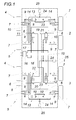
In der Zeichnung ist der Erfindungsgegenstand beispielhaft dargestellt. Es zeigen
- Fig. 1
- ein erfindungsgemäßes Nutzfahrzeug in einem schematischen Blockschaltbild und
- Fig. 2
- das Fahrgestell eines erfindungsgemäßen Nutzfahrzeugs in einer schematischen Draufsicht.
- Fig. 1
- a commercial vehicle according to the invention in a schematic block diagram and
- Fig. 2
- the chassis of a commercial vehicle according to the invention in a schematic plan view.
Das dargestellte Nutzfahrzeug 1 weist gemäß dem Blockschaltbild nach der
Die Lenkzylinder 11 und 12 werden über eine Steuereinrichtung 15 beaufschlagt, die alle Steuer- und Schaltelemente umfasst, um lediglich die vordere oder die hintere Tandemachse 2, 3 oder aber auch beide Tandemachsen 2, 3 zu leneken. Bei einer Allradlenkung kann über die Steuereinrichtung 15 im Bedarfsfall auch eine Beaufschlagung der Lenkzylinder 11, 12 für einen Hundegang gewählt werden. Die Lenkung selbst erfolgt für den über die Steuereinrichtung 15 einstellbaren Betriebszustand durch übliche Lenkventile 16.The
In der Zeichnung ist die Steuereinrichtung 15 durch die Andeutung entsprechender Schaltverbindungen in einer Schaltstellung für eine Allradlenkung gezeichnet. Man erkennt, dass die beiden Lenkzylinder 11, 12 in einer Reihenschaltung in den hydraulischen Lenkkreis eingebunden sind, sodass beispielsweise bei einer Beaufschlagung des Lenkzylinders 11 über die Druckleitung 17 die miteinander über die Lenkstange 10 verbundenen Achsschenkel 7 auf der linken Fahrzeugseite und über das hydraulische Gestänge 13 auch die Achsschenkel 7 der Achsen 4, 5 auf der rechten Fahrzeugseite gegen den Uhrzeigersinn verschwenkt werden. Die Räder der beiden Achsen 4, 5 der vorderen Tandemachse 2 werden somit auf beiden Fahrzeugseiten synchron gelenkt.In the drawing, the
Mit der Beaufschlagung des Lenkzylinders 11 wird auch der Lenkzylinder 12 beaufschlagt, weil das hydraulische Druckmittel durch den Kolben des Lenkzylinders 11 über die Druckleitung 18 in den Lenkzylinder 12 gepumpt wird, der demzufolge eine Auslenkung der Achsschenkel 7 der hinteren Tandemachse 3 im Uhrzeigersinn bedingt. Werden die Lenkventile 16 umgeschaltet, so wird der Lenkzylinder 12 über die Lenkventile 16 mit hydraulischem Druckmittel versorgt, sodass sich ein gegensinniger Lenkausschlag ergibt.With the action of the
Bei einer Drehmomentbeaufschlagung der beispielsweise im Uhrzeigersinn ausgelenkten Räder der hinteren Tandemachse 3 durch äußere Kräfte im Uhrzeigersinn kann diese Drehmomentbelastung der Achsschenkel 7 der hinteren Tandemachse 3 nicht über das hydraulische Druckmittel in der Druckleitung 18 aufgenommen werden, weil das hydraulische Druckmittel in diesem Fall zwischen den Kolben der Lenkzylinder 11 und 12 einer Sogbelastung unterworfen wird. Es besteht daher die Gefahr, dass fehlerhafte Lenkstellungen auftreten, die unter Umständen das Nutzfahrzeug 1 unlenkbar machen. Um solchen Fehlauslenkungen entgegenwirken zu können und eine zwingende Abhängigkeit zwischen den Lenkausschlägen der Achsschenkel 7 der vorderen und der hinteren Tandemachse 2, 3 sicherzustellen, werden die beiden Tandemachsen 2, 3 miteinander zusätzlich durch ein strichpunktiert angedeutetes hydraulisches Gestänge 19 verbunden, das zwei je einer Tandemachse 2, 3 zugeordnete Stellzylinder 20 und 21 aufweist, die an einem der Achsschenkel 7 dieser Tandemachsen 2, 3 angreifen.When torque is applied, for example, in the clockwise direction of the wheels of the
Wird demnach beispielsweise die hintere Tandemachse 3 durch äußere Kräfte mit einem Drehmoment beaufschlagt, das eine Zugbelastung des hydraulischen Druckmittels in der Druckleitung 18 bewirkt, so wird der Stellzylinder 20 über den zugehörigen Achsschenkel 7 mit der Wirkung beaufschlagt, dass über jeweils eine der die Stellzylinder 20 und 21 verbindenden Druckleitungen 22 der Stellzylinder 21 beaufschlagt wird, dessen Kolben sich jedoch am Achsschenkel 7 des zugehörigen Vorderrades abstützt und daher nur unter einer gleichzeitigen Verschwenkung der vorderen Tandemachse 2 verlagert werden kann, sodass über das hydraulische Gestänge 19 die Zwangsabhängigkeit der Lenkausschläge der beiden Tandemachsen 2, 3 sichergestellt wird.If, for example, the
Wie unmittelbar aus dem Ausführungsbeispiel ersichtlich wird, bedingen Leckverluste in den hydraulischen Gestängen 13 und 19, die ja jeweils einen geschlossenen Hydraulikkreis darstellen, eine Veränderung der Lenkgeometrie, die tunlichst zu vermeiden ist. Aus diesem Grund sind die die Stellzylinder 14 bzw. die Stellzylinder 20, 21 verbindenden Druckleitungen 23 bzw. 22 dieser hydraulischen Gestänge 13 bzw. 19 auf der Seite der Kolbenstangen über je ein Rückschlagventil 24 an einen Druckspeicher 25 für das hydraulische Druckmittel angeschlossen, über den in einfacher Art Leckverluste an hydraulischem Druckmittel ausgeglichen werden können.As can be seen directly from the exemplary embodiment, leakage losses in the
In der
Claims (5)
Applications Claiming Priority (1)
| Application Number | Priority Date | Filing Date | Title |
|---|---|---|---|
| AT11212012 | 2012-10-17 |
Publications (3)
| Publication Number | Publication Date |
|---|---|
| EP2722256A2 true EP2722256A2 (en) | 2014-04-23 |
| EP2722256A3 EP2722256A3 (en) | 2014-05-21 |
| EP2722256B1 EP2722256B1 (en) | 2015-06-10 |
Family
ID=49484091
Family Applications (1)
| Application Number | Title | Priority Date | Filing Date |
|---|---|---|---|
| EP13188725.9A Active EP2722256B1 (en) | 2012-10-17 | 2013-10-15 | Commercial vehicle |
Country Status (2)
| Country | Link |
|---|---|
| EP (1) | EP2722256B1 (en) |
| HU (1) | HUE025482T2 (en) |
Cited By (2)
| Publication number | Priority date | Publication date | Assignee | Title |
|---|---|---|---|---|
| CN110027606A (en) * | 2018-01-12 | 2019-07-19 | 芜湖联合新能源重卡产业技术研究院有限公司 | Commercial vehicle and its all-wheel control system |
| WO2019195886A1 (en) * | 2018-04-11 | 2019-10-17 | Bis Industries Limited | Heavy haul vehicle |
Citations (6)
| Publication number | Priority date | Publication date | Assignee | Title |
|---|---|---|---|---|
| DE4219876A1 (en) * | 1991-06-18 | 1992-12-24 | Juergen Hartig | Forestry vehicle with hydraulic drive control - regulates rotation ratio of inner and outer wheels to match curve radius |
| US5368121A (en) * | 1993-06-21 | 1994-11-29 | Priefert; William D. | Telescoping tractor frame |
| DE19510208A1 (en) * | 1995-03-21 | 1996-09-26 | Zahnradfabrik Friedrichshafen | Multi-axle steering system for vehicles |
| AT406571B (en) * | 1996-10-08 | 2000-06-26 | Al Faris Abdallah O | Motor vehicle having hydraulic all-wheel steering |
| EP1302434A1 (en) * | 2001-10-15 | 2003-04-16 | Mitsubishi Heavy Industries, Ltd. | Steering gear of loading and unloading vehicle |
| US20050279563A1 (en) * | 2004-06-16 | 2005-12-22 | Peterson Robin A | Steerable bogie |
-
2013
- 2013-10-15 HU HUE13188725A patent/HUE025482T2/en unknown
- 2013-10-15 EP EP13188725.9A patent/EP2722256B1/en active Active
Patent Citations (6)
| Publication number | Priority date | Publication date | Assignee | Title |
|---|---|---|---|---|
| DE4219876A1 (en) * | 1991-06-18 | 1992-12-24 | Juergen Hartig | Forestry vehicle with hydraulic drive control - regulates rotation ratio of inner and outer wheels to match curve radius |
| US5368121A (en) * | 1993-06-21 | 1994-11-29 | Priefert; William D. | Telescoping tractor frame |
| DE19510208A1 (en) * | 1995-03-21 | 1996-09-26 | Zahnradfabrik Friedrichshafen | Multi-axle steering system for vehicles |
| AT406571B (en) * | 1996-10-08 | 2000-06-26 | Al Faris Abdallah O | Motor vehicle having hydraulic all-wheel steering |
| EP1302434A1 (en) * | 2001-10-15 | 2003-04-16 | Mitsubishi Heavy Industries, Ltd. | Steering gear of loading and unloading vehicle |
| US20050279563A1 (en) * | 2004-06-16 | 2005-12-22 | Peterson Robin A | Steerable bogie |
Cited By (3)
| Publication number | Priority date | Publication date | Assignee | Title |
|---|---|---|---|---|
| CN110027606A (en) * | 2018-01-12 | 2019-07-19 | 芜湖联合新能源重卡产业技术研究院有限公司 | Commercial vehicle and its all-wheel control system |
| WO2019195886A1 (en) * | 2018-04-11 | 2019-10-17 | Bis Industries Limited | Heavy haul vehicle |
| US11135911B2 (en) | 2018-04-11 | 2021-10-05 | Rexx Innovation Pty Ltd | Heavy haul vehicle |
Also Published As
| Publication number | Publication date |
|---|---|
| HUE025482T2 (en) | 2016-10-28 |
| EP2722256B1 (en) | 2015-06-10 |
| EP2722256A3 (en) | 2014-05-21 |
Similar Documents
| Publication | Publication Date | Title |
|---|---|---|
| EP0925199B1 (en) | Wheel suspension with automatic camber response | |
| DE602004002248T2 (en) | Vehicle steering system | |
| DE1755810C3 (en) | ||
| DE3744304B4 (en) | Wheel suspension for a steerable wheel of a vehicle axle | |
| EP1557305B1 (en) | Vehicle trailer | |
| WO2006094795A1 (en) | Road-building machine | |
| EP3299260B1 (en) | Semi-trailer | |
| EP3652002A2 (en) | Axle assembly for a heavy-goods vehicle, heavy-goods vehicle with at least one such axle assembly and a hydraulic unit, in particular for adjusting an adjustable unit designed as a cylinder-piston arrangement | |
| DE112014002319B4 (en) | Suspension device for a turnable wheel | |
| EP2722256B1 (en) | Commercial vehicle | |
| EP1073578B1 (en) | Steering device | |
| DE102014004318A1 (en) | tugger | |
| DE202011108878U1 (en) | Hinterachslenkvorrichtung for trailers, especially for cutting unit carriage | |
| EP1972525B1 (en) | Automotive steering linkage | |
| EP2659758A1 (en) | Reversible plough | |
| DE102016204081A1 (en) | Arm | |
| EP2604491B1 (en) | Steering assembly for commercial vehicles which can be actuated on both sides | |
| EP3461660B1 (en) | Combine | |
| EP2343229B1 (en) | Steering axle | |
| DE202019001532U1 (en) | Vehicle, especially heavy-duty vehicle | |
| EP3718862B1 (en) | Vehicle, in particular heavy-duty vehicle | |
| EP3366550A1 (en) | Mechanical steering device for forced steering of commercial vehicle wheel suspension on semitrailers depending on the relative angle between a towing vehicle and following vehicle | |
| DE10351465A1 (en) | Chassis for heavy goods vehicle, has links forming axle-side support and connection member for pneumatic spring and shock absorber | |
| DE202004000605U1 (en) | Agricultural tractor trailer with hydraulically controlled tandem jointed cross shaft axle at rear end of trailer chassis | |
| DE102015116575A1 (en) | Agricultural trailer |
Legal Events
| Date | Code | Title | Description |
|---|---|---|---|
| PUAL | Search report despatched |
Free format text: ORIGINAL CODE: 0009013 |
|
| PUAI | Public reference made under article 153(3) epc to a published international application that has entered the european phase |
Free format text: ORIGINAL CODE: 0009012 |
|
| AK | Designated contracting states |
Kind code of ref document: A2 Designated state(s): AL AT BE BG CH CY CZ DE DK EE ES FI FR GB GR HR HU IE IS IT LI LT LU LV MC MK MT NL NO PL PT RO RS SE SI SK SM TR |
|
| AX | Request for extension of the european patent |
Extension state: BA ME |
|
| AK | Designated contracting states |
Kind code of ref document: A3 Designated state(s): AL AT BE BG CH CY CZ DE DK EE ES FI FR GB GR HR HU IE IS IT LI LT LU LV MC MK MT NL NO PL PT RO RS SE SI SK SM TR |
|
| AX | Request for extension of the european patent |
Extension state: BA ME |
|
| RIC1 | Information provided on ipc code assigned before grant |
Ipc: B62D 7/15 20060101ALI20140415BHEP Ipc: B62D 21/04 20060101ALI20140415BHEP Ipc: B62D 7/14 20060101AFI20140415BHEP Ipc: B62D 21/18 20060101ALI20140415BHEP |
|
| 17P | Request for examination filed |
Effective date: 20141111 |
|
| RBV | Designated contracting states (corrected) |
Designated state(s): AL AT BE BG CH CY CZ DE DK EE ES FI FR GB GR HR HU IE IS IT LI LT LU LV MC MK MT NL NO PL PT RO RS SE SI SK SM TR |
|
| GRAP | Despatch of communication of intention to grant a patent |
Free format text: ORIGINAL CODE: EPIDOSNIGR1 |
|
| RIC1 | Information provided on ipc code assigned before grant |
Ipc: B62D 7/14 20060101AFI20150115BHEP Ipc: B62D 21/18 20060101ALI20150115BHEP Ipc: B62D 7/15 20060101ALI20150115BHEP Ipc: B62D 21/04 20060101ALI20150115BHEP |
|
| INTG | Intention to grant announced |
Effective date: 20150129 |
|
| RIN1 | Information on inventor provided before grant (corrected) |
Inventor name: GOTTFRIED, JOHANN |
|
| GRAS | Grant fee paid |
Free format text: ORIGINAL CODE: EPIDOSNIGR3 |
|
| RIN1 | Information on inventor provided before grant (corrected) |
Inventor name: GOTTFRIED, ANTON JOHANN |
|
| GRAA | (expected) grant |
Free format text: ORIGINAL CODE: 0009210 |
|
| AK | Designated contracting states |
Kind code of ref document: B1 Designated state(s): AL AT BE BG CH CY CZ DE DK EE ES FI FR GB GR HR HU IE IS IT LI LT LU LV MC MK MT NL NO PL PT RO RS SE SI SK SM TR |
|
| REG | Reference to a national code |
Ref country code: GB Ref legal event code: FG4D Free format text: NOT ENGLISH |
|
| RIN1 | Information on inventor provided before grant (corrected) |
Inventor name: GOTTFRIED, ANTON JOHANN |
|
| REG | Reference to a national code |
Ref country code: CH Ref legal event code: EP |
|
| REG | Reference to a national code |
Ref country code: AT Ref legal event code: REF Ref document number: 730767 Country of ref document: AT Kind code of ref document: T Effective date: 20150715 |
|
| REG | Reference to a national code |
Ref country code: DE Ref legal event code: R096 Ref document number: 502013000736 Country of ref document: DE |
|
| REG | Reference to a national code |
Ref country code: IE Ref legal event code: FG4D Free format text: LANGUAGE OF EP DOCUMENT: GERMAN |
|
| REG | Reference to a national code |
Ref country code: SE Ref legal event code: TRGR |
|
| REG | Reference to a national code |
Ref country code: FR Ref legal event code: PLFP Year of fee payment: 3 |
|
| PG25 | Lapsed in a contracting state [announced via postgrant information from national office to epo] |
Ref country code: LT Free format text: LAPSE BECAUSE OF FAILURE TO SUBMIT A TRANSLATION OF THE DESCRIPTION OR TO PAY THE FEE WITHIN THE PRESCRIBED TIME-LIMIT Effective date: 20150610 Ref country code: NO Free format text: LAPSE BECAUSE OF FAILURE TO SUBMIT A TRANSLATION OF THE DESCRIPTION OR TO PAY THE FEE WITHIN THE PRESCRIBED TIME-LIMIT Effective date: 20150910 Ref country code: ES Free format text: LAPSE BECAUSE OF FAILURE TO SUBMIT A TRANSLATION OF THE DESCRIPTION OR TO PAY THE FEE WITHIN THE PRESCRIBED TIME-LIMIT Effective date: 20150610 |
|
| REG | Reference to a national code |
Ref country code: NL Ref legal event code: MP Effective date: 20150610 |
|
| PG25 | Lapsed in a contracting state [announced via postgrant information from national office to epo] |
Ref country code: RS Free format text: LAPSE BECAUSE OF FAILURE TO SUBMIT A TRANSLATION OF THE DESCRIPTION OR TO PAY THE FEE WITHIN THE PRESCRIBED TIME-LIMIT Effective date: 20150610 Ref country code: BG Free format text: LAPSE BECAUSE OF FAILURE TO SUBMIT A TRANSLATION OF THE DESCRIPTION OR TO PAY THE FEE WITHIN THE PRESCRIBED TIME-LIMIT Effective date: 20150910 Ref country code: GR Free format text: LAPSE BECAUSE OF FAILURE TO SUBMIT A TRANSLATION OF THE DESCRIPTION OR TO PAY THE FEE WITHIN THE PRESCRIBED TIME-LIMIT Effective date: 20150911 Ref country code: LV Free format text: LAPSE BECAUSE OF FAILURE TO SUBMIT A TRANSLATION OF THE DESCRIPTION OR TO PAY THE FEE WITHIN THE PRESCRIBED TIME-LIMIT Effective date: 20150610 |
|
| PG25 | Lapsed in a contracting state [announced via postgrant information from national office to epo] |
Ref country code: EE Free format text: LAPSE BECAUSE OF FAILURE TO SUBMIT A TRANSLATION OF THE DESCRIPTION OR TO PAY THE FEE WITHIN THE PRESCRIBED TIME-LIMIT Effective date: 20150610 |
|
| PG25 | Lapsed in a contracting state [announced via postgrant information from national office to epo] |
Ref country code: RO Free format text: LAPSE BECAUSE OF NON-PAYMENT OF DUE FEES Effective date: 20150610 Ref country code: PL Free format text: LAPSE BECAUSE OF FAILURE TO SUBMIT A TRANSLATION OF THE DESCRIPTION OR TO PAY THE FEE WITHIN THE PRESCRIBED TIME-LIMIT Effective date: 20150610 Ref country code: SK Free format text: LAPSE BECAUSE OF FAILURE TO SUBMIT A TRANSLATION OF THE DESCRIPTION OR TO PAY THE FEE WITHIN THE PRESCRIBED TIME-LIMIT Effective date: 20150610 Ref country code: IS Free format text: LAPSE BECAUSE OF FAILURE TO SUBMIT A TRANSLATION OF THE DESCRIPTION OR TO PAY THE FEE WITHIN THE PRESCRIBED TIME-LIMIT Effective date: 20151010 Ref country code: CZ Free format text: LAPSE BECAUSE OF FAILURE TO SUBMIT A TRANSLATION OF THE DESCRIPTION OR TO PAY THE FEE WITHIN THE PRESCRIBED TIME-LIMIT Effective date: 20150610 Ref country code: PT Free format text: LAPSE BECAUSE OF FAILURE TO SUBMIT A TRANSLATION OF THE DESCRIPTION OR TO PAY THE FEE WITHIN THE PRESCRIBED TIME-LIMIT Effective date: 20151012 |
|
| REG | Reference to a national code |
Ref country code: DE Ref legal event code: R097 Ref document number: 502013000736 Country of ref document: DE |
|
| PLBE | No opposition filed within time limit |
Free format text: ORIGINAL CODE: 0009261 |
|
| STAA | Information on the status of an ep patent application or granted ep patent |
Free format text: STATUS: NO OPPOSITION FILED WITHIN TIME LIMIT |
|
| PG25 | Lapsed in a contracting state [announced via postgrant information from national office to epo] |
Ref country code: DK Free format text: LAPSE BECAUSE OF FAILURE TO SUBMIT A TRANSLATION OF THE DESCRIPTION OR TO PAY THE FEE WITHIN THE PRESCRIBED TIME-LIMIT Effective date: 20150610 |
|
| 26N | No opposition filed |
Effective date: 20160311 |
|
| PG25 | Lapsed in a contracting state [announced via postgrant information from national office to epo] |
Ref country code: LU Free format text: LAPSE BECAUSE OF FAILURE TO SUBMIT A TRANSLATION OF THE DESCRIPTION OR TO PAY THE FEE WITHIN THE PRESCRIBED TIME-LIMIT Effective date: 20151015 Ref country code: SI Free format text: LAPSE BECAUSE OF FAILURE TO SUBMIT A TRANSLATION OF THE DESCRIPTION OR TO PAY THE FEE WITHIN THE PRESCRIBED TIME-LIMIT Effective date: 20150610 |
|
| PG25 | Lapsed in a contracting state [announced via postgrant information from national office to epo] |
Ref country code: MC Free format text: LAPSE BECAUSE OF FAILURE TO SUBMIT A TRANSLATION OF THE DESCRIPTION OR TO PAY THE FEE WITHIN THE PRESCRIBED TIME-LIMIT Effective date: 20150610 |
|
| REG | Reference to a national code |
Ref country code: IE Ref legal event code: MM4A |
|
| REG | Reference to a national code |
Ref country code: FR Ref legal event code: PLFP Year of fee payment: 4 |
|
| REG | Reference to a national code |
Ref country code: HU Ref legal event code: AG4A Ref document number: E025482 Country of ref document: HU |
|
| PG25 | Lapsed in a contracting state [announced via postgrant information from national office to epo] |
Ref country code: IE Free format text: LAPSE BECAUSE OF NON-PAYMENT OF DUE FEES Effective date: 20151015 |
|
| PG25 | Lapsed in a contracting state [announced via postgrant information from national office to epo] |
Ref country code: CY Free format text: LAPSE BECAUSE OF FAILURE TO SUBMIT A TRANSLATION OF THE DESCRIPTION OR TO PAY THE FEE WITHIN THE PRESCRIBED TIME-LIMIT Effective date: 20150610 Ref country code: NL Free format text: LAPSE BECAUSE OF FAILURE TO SUBMIT A TRANSLATION OF THE DESCRIPTION OR TO PAY THE FEE WITHIN THE PRESCRIBED TIME-LIMIT Effective date: 20150610 |
|
| PG25 | Lapsed in a contracting state [announced via postgrant information from national office to epo] |
Ref country code: HR Free format text: LAPSE BECAUSE OF FAILURE TO SUBMIT A TRANSLATION OF THE DESCRIPTION OR TO PAY THE FEE WITHIN THE PRESCRIBED TIME-LIMIT Effective date: 20150610 Ref country code: BE Free format text: LAPSE BECAUSE OF NON-PAYMENT OF DUE FEES Effective date: 20151031 |
|
| PG25 | Lapsed in a contracting state [announced via postgrant information from national office to epo] |
Ref country code: MT Free format text: LAPSE BECAUSE OF FAILURE TO SUBMIT A TRANSLATION OF THE DESCRIPTION OR TO PAY THE FEE WITHIN THE PRESCRIBED TIME-LIMIT Effective date: 20150610 |
|
| REG | Reference to a national code |
Ref country code: FR Ref legal event code: PLFP Year of fee payment: 5 |
|
| PG25 | Lapsed in a contracting state [announced via postgrant information from national office to epo] |
Ref country code: SM Free format text: LAPSE BECAUSE OF FAILURE TO SUBMIT A TRANSLATION OF THE DESCRIPTION OR TO PAY THE FEE WITHIN THE PRESCRIBED TIME-LIMIT Effective date: 20150610 |
|
| PG25 | Lapsed in a contracting state [announced via postgrant information from national office to epo] |
Ref country code: MK Free format text: LAPSE BECAUSE OF FAILURE TO SUBMIT A TRANSLATION OF THE DESCRIPTION OR TO PAY THE FEE WITHIN THE PRESCRIBED TIME-LIMIT Effective date: 20150610 |
|
| REG | Reference to a national code |
Ref country code: FR Ref legal event code: PLFP Year of fee payment: 6 |
|
| PG25 | Lapsed in a contracting state [announced via postgrant information from national office to epo] |
Ref country code: IT Free format text: LAPSE BECAUSE OF NON-PAYMENT OF DUE FEES Effective date: 20181015 Ref country code: TR Free format text: LAPSE BECAUSE OF FAILURE TO SUBMIT A TRANSLATION OF THE DESCRIPTION OR TO PAY THE FEE WITHIN THE PRESCRIBED TIME-LIMIT Effective date: 20150610 Ref country code: AL Free format text: LAPSE BECAUSE OF FAILURE TO SUBMIT A TRANSLATION OF THE DESCRIPTION OR TO PAY THE FEE WITHIN THE PRESCRIBED TIME-LIMIT Effective date: 20150610 |
|
| PG25 | Lapsed in a contracting state [announced via postgrant information from national office to epo] |
Ref country code: IT Free format text: LAPSE BECAUSE OF NON-PAYMENT OF DUE FEES Effective date: 20181015 |
|
| PGRI | Patent reinstated in contracting state [announced from national office to epo] |
Ref country code: IT Effective date: 20181205 |
|
| PGFP | Annual fee paid to national office [announced via postgrant information from national office to epo] |
Ref country code: GB Payment date: 20231025 Year of fee payment: 11 |
|
| PGFP | Annual fee paid to national office [announced via postgrant information from national office to epo] |
Ref country code: SE Payment date: 20231025 Year of fee payment: 11 Ref country code: IT Payment date: 20231013 Year of fee payment: 11 Ref country code: HU Payment date: 20231005 Year of fee payment: 11 Ref country code: FR Payment date: 20231023 Year of fee payment: 11 Ref country code: FI Payment date: 20231023 Year of fee payment: 11 Ref country code: DE Payment date: 20231013 Year of fee payment: 11 Ref country code: CH Payment date: 20231102 Year of fee payment: 11 Ref country code: AT Payment date: 20231013 Year of fee payment: 11 |