EP2722239A1 - Unité d'entraînement pour un système de sécurité d'un véhicule - Google Patents
Unité d'entraînement pour un système de sécurité d'un véhicule Download PDFInfo
- Publication number
- EP2722239A1 EP2722239A1 EP12007233.5A EP12007233A EP2722239A1 EP 2722239 A1 EP2722239 A1 EP 2722239A1 EP 12007233 A EP12007233 A EP 12007233A EP 2722239 A1 EP2722239 A1 EP 2722239A1
- Authority
- EP
- European Patent Office
- Prior art keywords
- drive
- drive unit
- rotor
- pyrotechnic
- gas
- Prior art date
- Legal status (The legal status is an assumption and is not a legal conclusion. Google has not performed a legal analysis and makes no representation as to the accuracy of the status listed.)
- Granted
Links
- 230000033001 locomotion Effects 0.000 claims description 19
- 230000001960 triggered effect Effects 0.000 claims description 6
- 208000027418 Wounds and injury Diseases 0.000 claims description 4
- 230000006378 damage Effects 0.000 claims description 4
- 208000014674 injury Diseases 0.000 claims description 3
- 239000002184 metal Substances 0.000 description 6
- 229910052751 metal Inorganic materials 0.000 description 6
- 238000006073 displacement reaction Methods 0.000 description 5
- 229910000831 Steel Inorganic materials 0.000 description 4
- 230000005540 biological transmission Effects 0.000 description 4
- 239000010959 steel Substances 0.000 description 4
- 239000000463 material Substances 0.000 description 3
- 230000009467 reduction Effects 0.000 description 3
- 241000446313 Lamella Species 0.000 description 2
- 230000001133 acceleration Effects 0.000 description 2
- 230000009471 action Effects 0.000 description 2
- 230000008901 benefit Effects 0.000 description 2
- 238000006243 chemical reaction Methods 0.000 description 2
- 238000010276 construction Methods 0.000 description 2
- 239000004033 plastic Substances 0.000 description 2
- 229920003023 plastic Polymers 0.000 description 2
- 230000002441 reversible effect Effects 0.000 description 2
- 229920002430 Fibre-reinforced plastic Polymers 0.000 description 1
- 238000005452 bending Methods 0.000 description 1
- 239000011248 coating agent Substances 0.000 description 1
- 238000000576 coating method Methods 0.000 description 1
- 230000006835 compression Effects 0.000 description 1
- 238000007906 compression Methods 0.000 description 1
- 230000008878 coupling Effects 0.000 description 1
- 238000010168 coupling process Methods 0.000 description 1
- 238000005859 coupling reaction Methods 0.000 description 1
- 238000004880 explosion Methods 0.000 description 1
- 239000011151 fibre-reinforced plastic Substances 0.000 description 1
- 231100001261 hazardous Toxicity 0.000 description 1
- 230000006698 induction Effects 0.000 description 1
- 230000004941 influx Effects 0.000 description 1
- 150000002739 metals Chemical class 0.000 description 1
- 238000000034 method Methods 0.000 description 1
- 230000008569 process Effects 0.000 description 1
- 230000001681 protective effect Effects 0.000 description 1
- 238000004080 punching Methods 0.000 description 1
- 230000009466 transformation Effects 0.000 description 1
- 238000004804 winding Methods 0.000 description 1
Images


Classifications
-
- B—PERFORMING OPERATIONS; TRANSPORTING
- B60—VEHICLES IN GENERAL
- B60R—VEHICLES, VEHICLE FITTINGS, OR VEHICLE PARTS, NOT OTHERWISE PROVIDED FOR
- B60R22/00—Safety belts or body harnesses in vehicles
- B60R22/34—Belt retractors, e.g. reels
- B60R22/46—Reels with means to tension the belt in an emergency by forced winding up
- B60R22/4628—Reels with means to tension the belt in an emergency by forced winding up characterised by fluid actuators, e.g. pyrotechnic gas generators
Definitions
- the invention relates to a drive unit for a safety system of a vehicle and to such a safety system.
- the object is achieved by a drive unit according to claim 1 and by a security system according to claim 14.
- the drive unit according to the invention for a safety system of a vehicle comprises at least one pyrotechnic drive.
- safety system refers to such a system which, in the event of an accident or a dangerous situation, ensures that at least one vehicle component is moved in order to increase safety for vehicle occupants, in particular in order to reduce a risk of injury to them.
- This refers in particular to belt tensioners or seat adjusters, wherein the pyrotechnic drive can support an electric motor in accident or dangerous situations, but also other systems are conceivable in which, for example, a vehicle seat, a console, an operating element or parts thereof are moved.
- Said pyrotechnic drive has a housing formed in a drive chamber with an outlet for gas.
- the housing encloses at least the said drive chamber, but may possibly also enclose other parts of the pyrotechnic drive.
- the drive chamber is preferably gas-tight.
- materials for the construction of the housing or the chamber wall various materials, in particular metals such as steel or high-strength fiber-reinforced plastics, come into question.
- the chamber can be coated on the inside, for example, with plastic to ensure a lower friction.
- a rotor In the drive chamber, a rotor is arranged, which is axially rotatably mounted.
- the term "axial” here is not to be interpreted as meaning that the rotor or the drive chamber necessarily have a certain (axial) symmetry. Rather, the axial direction is determined by the direction of the axis of rotation of the rotor, whereby the directions “tangential” and “radially” are defined.
- pyrotechnic drive on a pyrotechnic gas generator it is possible to use gas generators which are already known in the prior art and, for example, are used as described in cooperation with pistons or steel balls.
- pyrotechnic gas generator here means any device in which a targeted chemical reaction is triggered, which leads to gas evolution, typically in the form of an explosion or a targeted burnup.
- cartridges are used with biased gas in which, for example, a pyrotechnic gas generator destroys a rupture disc and thus releases the influx of gas from the cartridge to the drive unit.
- the gas generator is used to pressurize the rotor with gas pressure, whereby the rotor is driven.
- the gas generator is arranged on a pressure chamber which is connected to the drive chamber via a connection channel, which is tapered with respect to the pressure chamber.
- the arrangement of the gas generator is in this case selected such that released gas first flows into said pressure chamber.
- This of course includes designs in which the gas generator is arranged in said pressure chamber. But it can also be embedded, for example, in a wall of the pressure chamber.
- the connection channel fulfills two functions.
- a maximum transverse dimension (eg a diameter) of the connecting channel can hereby preferably be between 1% and 90%, more preferably between 5% and 70%, particularly preferably between 10% and 30% of a maximum dimension of the pressure chamber.
- both the pressure chamber and the connecting channel must be stable enough to withstand the occurring gas pressures, which is why they can be formed, for example, within a metal body.
- the dimensioning of the pressure chamber is advantageously comparatively large; their volume may for example be 0.5 times to 500 times, preferably 10 times to 100 times, the volume of the drive chamber. If a gas cartridge is used, its volume must be added to that of the pressure chamber.
- the rotor is designed in the manner of a disk motor.
- Such motors are known in the art, especially in connection with compressed air as a drive means.
- the rotor has a substantially cylindrical plate carrier, which is provided with radially extending slots, are inserted in the slats.
- the drive chamber is also cylindrical, but eccentric to the rotor so that it almost touches the wall of the chamber on one side, while at the opposite side there is a greater distance. On the latter side is typically the outlet opening, while the gas generated is first fed to the part in which the distance between the rotor and the wall is small.
- the lamellae provide a seal between the rotor and the wall, wherein they are typically pressed by centrifugal forces to the outside, whereby an at least predominantly gas-tight closure is ensured.
- the movement of the slats outward can - especially in the initial phase - are supported by gas is guided in the slots inside the slats and the slats are so pressurized with gas pressure.
- the rotor is designed as an impeller.
- the impeller may consist of a single piece, for example of a metal sheet.
- the impeller is flown in the direction of its axis of rotation from the gas. This may be the case in particular in the case of an axial arrangement of the gas generator and / or the pressure chamber.
- the impeller is tangential, ie perpendicular to the axis of rotation, is flown. This is conceivable in particular in the case of a radial arrangement of the gas generator and / or the pressure chamber.
- the drive unit according to the invention allows a small size, whereby it can be used flexibly.
- This flexibility can be further increased by the gas generator and / or the pressure chamber, if present, are arranged in different ways with respect to the rotor.
- one of said elements or both are arranged axially with respect to the rotor. This results in a slim design with respect to the axial direction.
- the gas generator and / or the pressure chamber are arranged radially with respect to the rotor. This is e.g. then advantageous if a shaft which is acted upon by the rotor, to be passed through the pyrotechnic drive, which is hardly possible in an axial arrangement. Furthermore, this arrangement is advantageous if, based on the axial direction, no slim, but a flat design is desired.
- the axial or radial arrangement with respect to the rotor corresponds to an axial or radial arrangement with respect to the drive chamber.
- the gas generator is particularly advantageously arranged on the end of the pressure chamber opposite the drive chamber or the rotor.
- the gas generator is detachably connected to the rest of the pyrotechnic drive. This can be achieved by various types of connections known in the art, such as by snap connections or screw connections.
- the gas generator with a housing part which forms part of the wall of the pressure chamber, is detachably connected, and that this housing part in turn is releasably connected to the rest of the housing.
- This can be especially a connection can be provided by means of a bayonet closure.
- the drive unit comprises a second drive.
- a further pyrotechnic drive is provided, which simultaneously or e.g. staggered in time with the pyrotechnic drive is used.
- it may be another type of drive, such as an electric drive, act.
- the other type of drive is normally used outside of an accident situation.
- An example of this would be a known in the art reversible belt tensioner, which acts by means of an electric drive in dangerous situations with a lower force on the belt.
- the pyrotechnic drive and the second drive can be arranged axially relative to one another and act on the same shaft. This too is a typical situation with a belt tensioner comprising an electric and a pyrotechnic drive.
- the second drive comprises an electric motor, in particular, for example, when both drives act on the same shaft.
- the drives are mechanically coupled to one another in this or in another way, overvoltage can occur due to the strong angular acceleration due to the pyrotechnic drive, the electric motor acting as a generator.
- the overvoltage can, for example, cause the electronics of the electric motor to be destroyed.
- the pyrotechnic drive is designed to trigger a circuit breaker of the electric motor during startup. By this measure, electronic components can be effectively protected from occurring voltage spikes.
- the phrase "at startup” expressly includes such embodiments in which the interruption of the circuit is not carried out simultaneously with the commissioning (ie in particular with the triggering of the gas generator), but with a certain delay; This can result, for example, due to the inertia of components, but is preferably less than 10 ms, more preferably less than 5 ms, particularly preferably less than 2 ms.
- a particularly effective way to implement the above-mentioned protective measure is that at least part of the pyrotechnic drive is axially and / or radially displaceable by applying gas pressure, whereby the circuit breaker is triggered.
- the drive unit preferably comprises a return element for returning the pyrotechnic drive or a part thereof to an initial position after a drop in the gas pressure.
- the displacement can take place, in particular, counter to a spring force, so that, after the gas pressure has been reduced, the displaced part of the pyrotechnic drive returns to its starting position.
- the said part of the drive can e.g. be part of the housing and / or the rotor itself may experience an axial displacement in addition to its tangential movement.
- a housing of the pyrotechnic drive is at least partially subdivided into a stationary outer housing and an axially displaceable inner housing.
- the shifting part of the pyrotechnic actuator can interact with a pressure switch that breaks the circuit.
- a spring element against the force of which the displacement takes place, form part of the circuit. In this case, the interruption of the circuit is effected by the deformation of the spring element.
- the rotational movement generated by the rotor can be used directly, for example, in a belt tensioner.
- the drive unit comprises a gear, with which at least one drive cooperates.
- a gear with which at least one drive cooperates.
- a transmission may include a combination of cooperating internal and external threads whereby the rotational movement of the rotor may be converted into a linear motion.
- the operating parameters of the pyrotechnic drive are influenced by different sizes. These include e.g. the energy released by the gas generator and the dimensioning of pressure chamber, connecting channel and rotor. Also by the design of the flow area between the pressure chamber and disk drive, the speed or an external load torque can be adjusted. However, in certain applications it may make sense to load the drive "artificially" with an additional moment of inertia, which also influences its dynamics. Therefore, in another embodiment, the drive unit comprises an inertia element connected to the pyrotechnic drive. Such an inertia element is coupled to the rotor, typically via a shaft, and has no other functions other than providing an additional moment of inertia. Since a high-density material is advantageous in this case, such an inertia element may consist in particular of metal.
- the drive unit comprises an unlocking element, wherein the gas generator is adapted to act on the unlocking element to release a movement of the drive unit.
- an unlocking element can interact either directly with a drive (eg with the rotor), with a gearbox or even with a vehicle component to be moved in order to lock it. It can thus be achieved, for example, increased stability, as long as the pyrotechnic drive is not triggered. In any case, the movement of the vehicle component is obstructed or impeded by the drive unit as long as the unlocking element is in the locked state. By the action the gas generator is unlocked.
- the gas generator can optionally apply gas pressure to the unlocking element or a mechanical intermediate element (eg a piston) which in turn mechanically acts on the unlocking element.
- a mechanical intermediate element eg a piston
- gas is applied to the rotor only after an unlocking process.
- the invention further provides a security system for a vehicle.
- This safety system comprises a drive unit according to the invention and a vehicle component, wherein the drive unit is designed to move the vehicle component in the event of an accident or a dangerous situation in order to reduce a risk of injury to occupants.
- Vehicles such as cars or trucks come into question here in particular as vehicles.
- the vehicle component may in particular be a rewinder of a safety belt.
- it may also be, as already mentioned, a vehicle seat, a console, an operating element, parts thereof or else.
- a first embodiment of a drive unit 1 according to the invention is shown.
- the drive unit 1 shown here consists of a pyrotechnic drive 10. This is encapsulated in a housing 11 having an opening 26 for receiving a shaft (not shown) for external power transmission. Opposite the opening 26 is another opening, not shown here, so that the shaft can be passed completely through the housing 11.
- a closure lid 24 is releasably connected to the rest of the housing 11.
- a first and second gas outlet opening 18, 19 can be seen.
- a drive chamber 12 is formed within the housing 11, which has a substantially cylindrical shape.
- the drive chamber 12 may in this case be formed in particular within a metal body, although an inner-side coating with plastic may be advantageous in order to minimize friction losses.
- a rotor 13 is arranged within the drive chamber 12. This comprises a substantially cylindrical plate carrier 14, which is provided with the approximately radially extending slots 15. In these slots 15 slats 16 are used.
- the plate carrier 14 also has a centrally disposed recess 17 for receiving a shaft. An axial direction of a rotation axis of the rotor 13 is defined by way of this.
- the drive 10 operates on the principle of a multi-disk motor.
- Fig.2 shows, the rotor 13 with respect to the drive chamber 12 arranged eccentrically.
- a connecting channel 21 opens into the drive chamber 12.
- connection channel 21 the drive chamber 12 communicates with a pressure chamber 20 in connection.
- both the connecting channel 21 and the pressure chamber 20 are constructed substantially cylindrical, although the transverse dimension of the connecting channel 21 is only about one fifth of that of the pressure chamber 20.
- the closure lid 24 in this case forms an end-side closure of the pressure chamber 20.
- a micro gas generator 22 is arranged, which is connected via a snap closure 25 with the closure lid 24.
- a second, smaller connection channel (not shown) is provided, which connects the pressure chamber 20 with a part of the drive chamber 12, which is adjacent to the (radially) inner ends of the slots 15 of the rotor 13. This can be applied to these areas with gas pressure to actively push the fins 16 to the outside.
- the micro gas generator 22 can be ignited electrically in a known manner, for example via the airbag control of a vehicle. If this happens, a high gas pressure builds up within the pressure chamber 20 due to the gas evolution. The resulting pressure wave reaches the working chamber 12 via the connecting channel 21 and begins to drive the rotor 13 on the way to the outlet openings 18, 19. After a short start-up phase, which is in the range of a few milliseconds, typically even less than 1 millisecond, the fins 16 in the slots 15 are due to the centrifugal forces and by the pressure of the guided over the second connecting channel behind the fins 16 gas to the outside Wall of the drive chamber 12 is pressed, whereby a substantially gas-tight closure is formed. This condition is in Fig.2 already shown. The resulting rotational movement of the rotor 13 can be transmitted via a shaft to a vehicle element, for example a belt winder. The pyrotechnic drive 10 in this case enables a very fast provision of high torques.
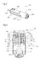
- Fig.3-5 show an alternative embodiment of a drive unit 101.
- this includes in addition to a pyrotechnic drive 110 and a DC motor 140, the side has a connection socket 153 for power supply.
- the said drives 110, 140 act in this case directly on the same shaft 150 a.
- a typical application example of such a configuration is a belt tensioner in which the DC motor 140 provides a reversible drive for potential hazardous situations, while the pyrotechnic drive 110 is provided for accident situations.
- the two drives 110,140 are arranged axially to each other in this embodiment, wherein the entire drive unit 101 has an elongated, approximately cylindrical shape.
- a rotor 113 of the pyrotechnic drive 110 is mounted with a central recess 117 on the shaft 150 and in this case together with this rotatable about an axial direction.
- the rotor 113 is again formed as a plate carrier 114 with inserted into slots 115 fins 116. It is arranged eccentrically in a substantially cylindrical drive chamber 112, which is bounded radially outwardly by an outlet housing 128 in the same manner as in the embodiment shown in FIGS.
- a pressure chamber 120 with a microgas generator 122 arranged therein is not arranged radially but axially relative to the rotor 113.
- the pressure chamber 120 is bounded radially outwards and in the direction of the drive chamber 112 by a pressure housing 127.
- the pressure housing 127 and the axially adjacent outlet housing 128 are arranged axially displaceable within an outer shell housing 111.
- the rotor 113 is rotatably, but axially displaceably connected to the shaft 150.
- a first end member 131 and - in the direction of the pressure chamber 120 - a second end member 132 are arranged, which are each disk-shaped and corresponding to the diameter of the disk carrier 114. However, they are not rotatably connected to the shaft 150 and do not rotate with the rotor 113. They too are axially displaceable.
- pressure chamber 120 and micro gas generator 122 are here substantially identical to the embodiment already discussed. However, in this case, the arrangement and shape of a connecting passage 121 passing through the pressure housing 127 and the outlet housing 128 and connecting the pressure chamber 120 and the driving chamber 112 are different.
- the connecting channel 121 initially leads axially from the pressure chamber in the direction of the drive chamber 112 and then from outside to inside in the radial direction into the drive chamber 112.
- By arrows with dashed lines is in Figure 4 and 5 the path of the gas generated by the micro gas generator 122 indicated, this flows through the connecting channel 121 in the drive chamber 112, the rotor 113 in rotational movement and finally flows out through an outlet openings 118 from.
- the extension of the fins 116 is also supported by the gas pressure in the drive 110 shown here.
- the second closing element 132 has a passage opening 134 which, when installed, adjoins the passage channel 133.
- an inner portion of the slots 115 can be pressurized with gas pressure to push the fins 116 to the outside.
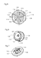
- connection between these contacts 151 is normally made by a plate spring 152, which on the first end member 131st rests and rotationally fixed in an abutment 130 is inserted, which in turn is connected to the jacket housing 111. That is, by the plate spring 152, the circuit of the DC motor 140 is closed.
- the arrangement of the cross-shaped plate spring 152 in the abutment 130 is in Figure 7 to recognize.
- the interruption of the circuit is achieved by a displacement of parts of the pyrotechnic actuator 110. Due to the axial displaceability of the pressure housing 127, the outlet housing 128, the rotor 113 and the end elements 131, 132, the pressure chamber 120 can expand to a slight extent when pressure is applied to an end face 129 facing the drive chamber 112. In this case, a compression of the plate spring 152, whereby on the one hand a restoring force is given, on the other hand, an interruption of the circuit takes place, since the plate spring 152 is no longer in contact with the contacts 151. After reducing the pressure in the pressure chamber, i. After the operation of the pyrotechnic actuator 110 is completed, the axially displaced elements 113, 127, 128, 131, 132 are pushed back into their original position, whereby the circuit of the DC motor 140 is closed again.
- the pyrotechnic drive 110 shown here has a diameter of about 30 mm and a length of about 53 mm.
- the volume of the pressure chamber 120 is approximately 12 cm 3 .
- an average torque of approximately 1.4 Nm and a speed of 1380 U / s can be made available within the first 50 ms.
- the values mentioned here are in no way restrictive with regard to the invention, but are merely intended to illustrate that a high performance can be achieved with a very small design.
- FIG 8 shows a further embodiment of a drive unit 201 according to the invention, which is provided for a seat adjuster of a motor vehicle.
- the drive unit 201 in turn has only one pyrotechnic drive 210. This is intended to be installed between the body and the seat rail of a motor vehicle (not shown).
- a housing 211 of the drive 210 only partially shown. In fact, this forms, as in the already discussed embodiments, a largely gas-tight jacket for a drive chamber 212, in which a rotor 213 is rotatably mounted.
- the rotor 213 is designed here as an impeller. This is made of a circular disc-shaped sheet-metal disc, wherein wings 214 were formed by partially punching and bending of outer portions of the circular disc.
- the rotor 213 has a central recess 215 with serrated edge.
- the rotor 213 is rotatably connected to a cylindrical sleeve member 216 having an internal thread (not shown).
- the internal thread cooperates with an external thread 237 of a lifting bolt 236, which is guided through the sleeve element 216 and through the central recess 215 of the rotor 213.
- the lifting pin 236 is secured against rotation with the seat rail. Upon rotation of the external thread, an axial displacement of the lifting bolt 236 therefore takes place via the internal thread 237.
Landscapes
- Engineering & Computer Science (AREA)
- Mechanical Engineering (AREA)
- Automotive Seat Belt Assembly (AREA)
Priority Applications (2)
| Application Number | Priority Date | Filing Date | Title |
|---|---|---|---|
| EP12007233.5A EP2722239B1 (fr) | 2012-10-19 | 2012-10-19 | Unité d'entraînement pour un système de sécurité d'un véhicule |
| EP20130179282 EP2684748B1 (fr) | 2012-10-19 | 2013-08-05 | Unité d'activation pour un système de sécurisation d'un véhicule automobile |
Applications Claiming Priority (1)
| Application Number | Priority Date | Filing Date | Title |
|---|---|---|---|
| EP12007233.5A EP2722239B1 (fr) | 2012-10-19 | 2012-10-19 | Unité d'entraînement pour un système de sécurité d'un véhicule |
Publications (2)
| Publication Number | Publication Date |
|---|---|
| EP2722239A1 true EP2722239A1 (fr) | 2014-04-23 |
| EP2722239B1 EP2722239B1 (fr) | 2015-04-01 |
Family
ID=47216006
Family Applications (1)
| Application Number | Title | Priority Date | Filing Date |
|---|---|---|---|
| EP12007233.5A Active EP2722239B1 (fr) | 2012-10-19 | 2012-10-19 | Unité d'entraînement pour un système de sécurité d'un véhicule |
Country Status (1)
| Country | Link |
|---|---|
| EP (1) | EP2722239B1 (fr) |
Citations (3)
| Publication number | Priority date | Publication date | Assignee | Title |
|---|---|---|---|---|
| DE2814487A1 (de) * | 1978-04-04 | 1979-10-11 | Repa Feinstanzwerk Gmbh | Rueckstrammer mit pyrotechnischem treibsatz fuer sicherheitsgurtwickelautomaten |
| DE3606021A1 (de) * | 1986-02-25 | 1987-08-27 | Ernst Hans Hellmut | Rotatorischer gurtstrammer fuer sicherheitsgurte |
| GB2314755A (en) * | 1996-07-05 | 1998-01-14 | Autoliv Dev | Safety belt pretensioner with energy absorbing means |
Family Cites Families (3)
| Publication number | Priority date | Publication date | Assignee | Title |
|---|---|---|---|---|
| DE19614997A1 (de) * | 1996-04-16 | 1997-10-23 | Hs Tech & Design | Vorrichtung zum Gurtstraffen |
| DE29609691U1 (de) * | 1996-05-31 | 1996-10-17 | Foehl Artur | Pyrotechnische Antriebseinrichtung für einen Gurtstraffer |
| JPH10238216A (ja) * | 1996-12-27 | 1998-09-08 | Nippon Kuatsu Syst Kk | ドアガラス開放装置 |
-
2012
- 2012-10-19 EP EP12007233.5A patent/EP2722239B1/fr active Active
Patent Citations (3)
| Publication number | Priority date | Publication date | Assignee | Title |
|---|---|---|---|---|
| DE2814487A1 (de) * | 1978-04-04 | 1979-10-11 | Repa Feinstanzwerk Gmbh | Rueckstrammer mit pyrotechnischem treibsatz fuer sicherheitsgurtwickelautomaten |
| DE3606021A1 (de) * | 1986-02-25 | 1987-08-27 | Ernst Hans Hellmut | Rotatorischer gurtstrammer fuer sicherheitsgurte |
| GB2314755A (en) * | 1996-07-05 | 1998-01-14 | Autoliv Dev | Safety belt pretensioner with energy absorbing means |
Also Published As
| Publication number | Publication date |
|---|---|
| EP2722239B1 (fr) | 2015-04-01 |
Similar Documents
| Publication | Publication Date | Title |
|---|---|---|
| EP3516251B1 (fr) | Système d'actionnement et dispositif embrayage pour un véhicule automobile | |
| EP2785566B1 (fr) | Enrouleur de ceinture doté de deux dispositifs de limitation de la force agissant en parallèle | |
| EP3268260B1 (fr) | Colonne de direction pour un véhicule automobile | |
| DE102016214709A1 (de) | Lenksäule für ein Kraftfahrzeug | |
| EP3939839B1 (fr) | Rétracteur comportant un dispositif de limitation de force pourvu de dispositif de découplage | |
| EP3655274B1 (fr) | Module hybride | |
| WO1997049583A1 (fr) | Enrouleur de ceinture de securite muni d'un limiteur de force regulable | |
| WO2007068452A1 (fr) | Tendeur de ceinture pour un système de ceinture de sécurité | |
| DE102011008405A1 (de) | Gurtaufroller mit einer geschwindigkeitsgeregelten Kraftbegrenzungseinrichtung | |
| EP3665063B1 (fr) | Colonne de direction pour un véhicule automobile | |
| WO2015055570A1 (fr) | Dispositif limiteur de force pour système de ceinture de sécurité | |
| DE102011101517B4 (de) | Kraftbegrenzungseinrichtung für ein Kraftfahrzeug und Gurtaufroller | |
| EP3472023B1 (fr) | Colonne de direction pour véhicule à moteur | |
| EP3523096B1 (fr) | Outil de travail | |
| DE102010026285A1 (de) | Kraftbegrenzungseinrichtung für ein Kraftfahrzeug | |
| DE102011101481B4 (de) | Gurtaufroller mit einer geschwindigkeitsgeregelten Kraftbegrenzungseinrichtung | |
| EP1525123B1 (fr) | Combine enrouleur de ceinture-pretensionneur de ceinture comprenant une commande de pretensionneur integree dans l'arbre de ceinture | |
| DE102011101518B4 (de) | Kraftbegrenzungseinrichtung für ein Kraftfahrzeug und Gurtaufroller | |
| DE102014207297A1 (de) | Gurtaufroller für eine Sicherheitsgurteinrichtung | |
| EP2722239B1 (fr) | Unité d'entraînement pour un système de sécurité d'un véhicule | |
| DE102018130819A1 (de) | Elektrische Achsantriebseinheit mit integrierter Bremseinrichtung | |
| EP3123048B1 (fr) | Dispositif de rattrapage à commande proportionnelle à la course pour embrayage à friction | |
| EP3805054A1 (fr) | Unité de moteur électrique pour un dispositif de pré-tension réversible et procédé de fonctionnement d'un dispositif de pré-tension réversible | |
| DE102006002756B4 (de) | Antriebsvorrichtung | |
| DE102013217236B4 (de) | Gurtaufroller für einen Sicherheitsgurt eines Kraftfahrzeuges |
Legal Events
| Date | Code | Title | Description |
|---|---|---|---|
| PUAI | Public reference made under article 153(3) epc to a published international application that has entered the european phase |
Free format text: ORIGINAL CODE: 0009012 |
|
| AK | Designated contracting states |
Kind code of ref document: A1 Designated state(s): AL AT BE BG CH CY CZ DE DK EE ES FI FR GB GR HR HU IE IS IT LI LT LU LV MC MK MT NL NO PL PT RO RS SE SI SK SM TR |
|
| AX | Request for extension of the european patent |
Extension state: BA ME |
|
| 17P | Request for examination filed |
Effective date: 20141006 |
|
| RBV | Designated contracting states (corrected) |
Designated state(s): AL AT BE BG CH CY CZ DE DK EE ES FI FR GB GR HR HU IE IS IT LI LT LU LV MC MK MT NL NO PL PT RO RS SE SI SK SM TR |
|
| GRAP | Despatch of communication of intention to grant a patent |
Free format text: ORIGINAL CODE: EPIDOSNIGR1 |
|
| INTG | Intention to grant announced |
Effective date: 20141219 |
|
| GRAS | Grant fee paid |
Free format text: ORIGINAL CODE: EPIDOSNIGR3 |
|
| GRAA | (expected) grant |
Free format text: ORIGINAL CODE: 0009210 |
|
| AK | Designated contracting states |
Kind code of ref document: B1 Designated state(s): AL AT BE BG CH CY CZ DE DK EE ES FI FR GB GR HR HU IE IS IT LI LT LU LV MC MK MT NL NO PL PT RO RS SE SI SK SM TR |
|
| REG | Reference to a national code |
Ref country code: GB Ref legal event code: FG4D Free format text: NOT ENGLISH |
|
| REG | Reference to a national code |
Ref country code: CH Ref legal event code: EP |
|
| REG | Reference to a national code |
Ref country code: IE Ref legal event code: FG4D Free format text: LANGUAGE OF EP DOCUMENT: GERMAN |
|
| REG | Reference to a national code |
Ref country code: AT Ref legal event code: REF Ref document number: 718876 Country of ref document: AT Kind code of ref document: T Effective date: 20150515 |
|
| REG | Reference to a national code |
Ref country code: DE Ref legal event code: R096 Ref document number: 502012002666 Country of ref document: DE Effective date: 20150521 |
|
| REG | Reference to a national code |
Ref country code: NL Ref legal event code: VDEP Effective date: 20150401 |
|
| REG | Reference to a national code |
Ref country code: LT Ref legal event code: MG4D |
|
| PG25 | Lapsed in a contracting state [announced via postgrant information from national office to epo] |
Ref country code: NL Free format text: LAPSE BECAUSE OF FAILURE TO SUBMIT A TRANSLATION OF THE DESCRIPTION OR TO PAY THE FEE WITHIN THE PRESCRIBED TIME-LIMIT Effective date: 20150401 |
|
| PG25 | Lapsed in a contracting state [announced via postgrant information from national office to epo] |
Ref country code: CZ Free format text: LAPSE BECAUSE OF FAILURE TO SUBMIT A TRANSLATION OF THE DESCRIPTION OR TO PAY THE FEE WITHIN THE PRESCRIBED TIME-LIMIT Effective date: 20150401 Ref country code: NO Free format text: LAPSE BECAUSE OF FAILURE TO SUBMIT A TRANSLATION OF THE DESCRIPTION OR TO PAY THE FEE WITHIN THE PRESCRIBED TIME-LIMIT Effective date: 20150701 Ref country code: PT Free format text: LAPSE BECAUSE OF FAILURE TO SUBMIT A TRANSLATION OF THE DESCRIPTION OR TO PAY THE FEE WITHIN THE PRESCRIBED TIME-LIMIT Effective date: 20150803 Ref country code: HR Free format text: LAPSE BECAUSE OF FAILURE TO SUBMIT A TRANSLATION OF THE DESCRIPTION OR TO PAY THE FEE WITHIN THE PRESCRIBED TIME-LIMIT Effective date: 20150401 Ref country code: ES Free format text: LAPSE BECAUSE OF FAILURE TO SUBMIT A TRANSLATION OF THE DESCRIPTION OR TO PAY THE FEE WITHIN THE PRESCRIBED TIME-LIMIT Effective date: 20150401 Ref country code: LT Free format text: LAPSE BECAUSE OF FAILURE TO SUBMIT A TRANSLATION OF THE DESCRIPTION OR TO PAY THE FEE WITHIN THE PRESCRIBED TIME-LIMIT Effective date: 20150401 Ref country code: FI Free format text: LAPSE BECAUSE OF FAILURE TO SUBMIT A TRANSLATION OF THE DESCRIPTION OR TO PAY THE FEE WITHIN THE PRESCRIBED TIME-LIMIT Effective date: 20150401 |
|
| PG25 | Lapsed in a contracting state [announced via postgrant information from national office to epo] |
Ref country code: IS Free format text: LAPSE BECAUSE OF FAILURE TO SUBMIT A TRANSLATION OF THE DESCRIPTION OR TO PAY THE FEE WITHIN THE PRESCRIBED TIME-LIMIT Effective date: 20150801 Ref country code: RS Free format text: LAPSE BECAUSE OF FAILURE TO SUBMIT A TRANSLATION OF THE DESCRIPTION OR TO PAY THE FEE WITHIN THE PRESCRIBED TIME-LIMIT Effective date: 20150401 Ref country code: LV Free format text: LAPSE BECAUSE OF FAILURE TO SUBMIT A TRANSLATION OF THE DESCRIPTION OR TO PAY THE FEE WITHIN THE PRESCRIBED TIME-LIMIT Effective date: 20150401 Ref country code: GR Free format text: LAPSE BECAUSE OF FAILURE TO SUBMIT A TRANSLATION OF THE DESCRIPTION OR TO PAY THE FEE WITHIN THE PRESCRIBED TIME-LIMIT Effective date: 20150702 |
|
| REG | Reference to a national code |
Ref country code: DE Ref legal event code: R097 Ref document number: 502012002666 Country of ref document: DE |
|
| PG25 | Lapsed in a contracting state [announced via postgrant information from national office to epo] |
Ref country code: DK Free format text: LAPSE BECAUSE OF FAILURE TO SUBMIT A TRANSLATION OF THE DESCRIPTION OR TO PAY THE FEE WITHIN THE PRESCRIBED TIME-LIMIT Effective date: 20150401 Ref country code: EE Free format text: LAPSE BECAUSE OF FAILURE TO SUBMIT A TRANSLATION OF THE DESCRIPTION OR TO PAY THE FEE WITHIN THE PRESCRIBED TIME-LIMIT Effective date: 20150401 |
|
| PLBE | No opposition filed within time limit |
Free format text: ORIGINAL CODE: 0009261 |
|
| STAA | Information on the status of an ep patent application or granted ep patent |
Free format text: STATUS: NO OPPOSITION FILED WITHIN TIME LIMIT |
|
| PG25 | Lapsed in a contracting state [announced via postgrant information from national office to epo] |
Ref country code: SK Free format text: LAPSE BECAUSE OF FAILURE TO SUBMIT A TRANSLATION OF THE DESCRIPTION OR TO PAY THE FEE WITHIN THE PRESCRIBED TIME-LIMIT Effective date: 20150401 Ref country code: RO Free format text: LAPSE BECAUSE OF NON-PAYMENT OF DUE FEES Effective date: 20150401 Ref country code: PL Free format text: LAPSE BECAUSE OF FAILURE TO SUBMIT A TRANSLATION OF THE DESCRIPTION OR TO PAY THE FEE WITHIN THE PRESCRIBED TIME-LIMIT Effective date: 20150401 |
|
| 26N | No opposition filed |
Effective date: 20160105 |
|
| PG25 | Lapsed in a contracting state [announced via postgrant information from national office to epo] |
Ref country code: IT Free format text: LAPSE BECAUSE OF FAILURE TO SUBMIT A TRANSLATION OF THE DESCRIPTION OR TO PAY THE FEE WITHIN THE PRESCRIBED TIME-LIMIT Effective date: 20150401 |
|
| PG25 | Lapsed in a contracting state [announced via postgrant information from national office to epo] |
Ref country code: LU Free format text: LAPSE BECAUSE OF FAILURE TO SUBMIT A TRANSLATION OF THE DESCRIPTION OR TO PAY THE FEE WITHIN THE PRESCRIBED TIME-LIMIT Effective date: 20151019 Ref country code: SI Free format text: LAPSE BECAUSE OF FAILURE TO SUBMIT A TRANSLATION OF THE DESCRIPTION OR TO PAY THE FEE WITHIN THE PRESCRIBED TIME-LIMIT Effective date: 20150401 |
|
| REG | Reference to a national code |
Ref country code: CH Ref legal event code: PL |
|
| PG25 | Lapsed in a contracting state [announced via postgrant information from national office to epo] |
Ref country code: MC Free format text: LAPSE BECAUSE OF FAILURE TO SUBMIT A TRANSLATION OF THE DESCRIPTION OR TO PAY THE FEE WITHIN THE PRESCRIBED TIME-LIMIT Effective date: 20150401 |
|
| REG | Reference to a national code |
Ref country code: IE Ref legal event code: MM4A |
|
| PG25 | Lapsed in a contracting state [announced via postgrant information from national office to epo] |
Ref country code: LI Free format text: LAPSE BECAUSE OF NON-PAYMENT OF DUE FEES Effective date: 20151031 Ref country code: CH Free format text: LAPSE BECAUSE OF NON-PAYMENT OF DUE FEES Effective date: 20151031 |
|
| REG | Reference to a national code |
Ref country code: FR Ref legal event code: ST Effective date: 20160630 |
|
| PG25 | Lapsed in a contracting state [announced via postgrant information from national office to epo] |
Ref country code: FR Free format text: LAPSE BECAUSE OF NON-PAYMENT OF DUE FEES Effective date: 20151102 |
|
| PG25 | Lapsed in a contracting state [announced via postgrant information from national office to epo] |
Ref country code: IE Free format text: LAPSE BECAUSE OF NON-PAYMENT OF DUE FEES Effective date: 20151019 |
|
| PG25 | Lapsed in a contracting state [announced via postgrant information from national office to epo] |
Ref country code: SM Free format text: LAPSE BECAUSE OF FAILURE TO SUBMIT A TRANSLATION OF THE DESCRIPTION OR TO PAY THE FEE WITHIN THE PRESCRIBED TIME-LIMIT Effective date: 20150401 Ref country code: BG Free format text: LAPSE BECAUSE OF FAILURE TO SUBMIT A TRANSLATION OF THE DESCRIPTION OR TO PAY THE FEE WITHIN THE PRESCRIBED TIME-LIMIT Effective date: 20150401 Ref country code: HU Free format text: LAPSE BECAUSE OF FAILURE TO SUBMIT A TRANSLATION OF THE DESCRIPTION OR TO PAY THE FEE WITHIN THE PRESCRIBED TIME-LIMIT; INVALID AB INITIO Effective date: 20121019 |
|
| GBPC | Gb: european patent ceased through non-payment of renewal fee |
Effective date: 20161019 |
|
| PG25 | Lapsed in a contracting state [announced via postgrant information from national office to epo] |
Ref country code: CY Free format text: LAPSE BECAUSE OF FAILURE TO SUBMIT A TRANSLATION OF THE DESCRIPTION OR TO PAY THE FEE WITHIN THE PRESCRIBED TIME-LIMIT Effective date: 20150401 Ref country code: SE Free format text: LAPSE BECAUSE OF FAILURE TO SUBMIT A TRANSLATION OF THE DESCRIPTION OR TO PAY THE FEE WITHIN THE PRESCRIBED TIME-LIMIT Effective date: 20150401 |
|
| PG25 | Lapsed in a contracting state [announced via postgrant information from national office to epo] |
Ref country code: GB Free format text: LAPSE BECAUSE OF NON-PAYMENT OF DUE FEES Effective date: 20161019 Ref country code: BE Free format text: LAPSE BECAUSE OF NON-PAYMENT OF DUE FEES Effective date: 20151031 |
|
| PG25 | Lapsed in a contracting state [announced via postgrant information from national office to epo] |
Ref country code: MT Free format text: LAPSE BECAUSE OF FAILURE TO SUBMIT A TRANSLATION OF THE DESCRIPTION OR TO PAY THE FEE WITHIN THE PRESCRIBED TIME-LIMIT Effective date: 20150401 |
|
| PG25 | Lapsed in a contracting state [announced via postgrant information from national office to epo] |
Ref country code: MK Free format text: LAPSE BECAUSE OF FAILURE TO SUBMIT A TRANSLATION OF THE DESCRIPTION OR TO PAY THE FEE WITHIN THE PRESCRIBED TIME-LIMIT Effective date: 20150401 |
|
| PG25 | Lapsed in a contracting state [announced via postgrant information from national office to epo] |
Ref country code: TR Free format text: LAPSE BECAUSE OF FAILURE TO SUBMIT A TRANSLATION OF THE DESCRIPTION OR TO PAY THE FEE WITHIN THE PRESCRIBED TIME-LIMIT Effective date: 20150401 Ref country code: AL Free format text: LAPSE BECAUSE OF FAILURE TO SUBMIT A TRANSLATION OF THE DESCRIPTION OR TO PAY THE FEE WITHIN THE PRESCRIBED TIME-LIMIT Effective date: 20150401 |
|
| REG | Reference to a national code |
Ref country code: AT Ref legal event code: MM01 Ref document number: 718876 Country of ref document: AT Kind code of ref document: T Effective date: 20171019 |
|
| PG25 | Lapsed in a contracting state [announced via postgrant information from national office to epo] |
Ref country code: AT Free format text: LAPSE BECAUSE OF NON-PAYMENT OF DUE FEES Effective date: 20171019 |
|
| P01 | Opt-out of the competence of the unified patent court (upc) registered |
Effective date: 20230531 |
|
| PGFP | Annual fee paid to national office [announced via postgrant information from national office to epo] |
Ref country code: DE Payment date: 20230929 Year of fee payment: 12 |