EP2722239A1 - Drive unit for a safety system of a vehicle - Google Patents
Drive unit for a safety system of a vehicle Download PDFInfo
- Publication number
- EP2722239A1 EP2722239A1 EP12007233.5A EP12007233A EP2722239A1 EP 2722239 A1 EP2722239 A1 EP 2722239A1 EP 12007233 A EP12007233 A EP 12007233A EP 2722239 A1 EP2722239 A1 EP 2722239A1
- Authority
- EP
- European Patent Office
- Prior art keywords
- drive
- drive unit
- rotor
- pyrotechnic
- gas
- Prior art date
- Legal status (The legal status is an assumption and is not a legal conclusion. Google has not performed a legal analysis and makes no representation as to the accuracy of the status listed.)
- Granted
Links
- 230000033001 locomotion Effects 0.000 claims description 19
- 230000001960 triggered effect Effects 0.000 claims description 6
- 208000027418 Wounds and injury Diseases 0.000 claims description 4
- 230000006378 damage Effects 0.000 claims description 4
- 208000014674 injury Diseases 0.000 claims description 3
- 239000002184 metal Substances 0.000 description 6
- 229910052751 metal Inorganic materials 0.000 description 6
- 238000006073 displacement reaction Methods 0.000 description 5
- 229910000831 Steel Inorganic materials 0.000 description 4
- 230000005540 biological transmission Effects 0.000 description 4
- 239000010959 steel Substances 0.000 description 4
- 239000000463 material Substances 0.000 description 3
- 230000009467 reduction Effects 0.000 description 3
- 241000446313 Lamella Species 0.000 description 2
- 230000001133 acceleration Effects 0.000 description 2
- 230000009471 action Effects 0.000 description 2
- 230000008901 benefit Effects 0.000 description 2
- 238000006243 chemical reaction Methods 0.000 description 2
- 238000010276 construction Methods 0.000 description 2
- 239000004033 plastic Substances 0.000 description 2
- 229920003023 plastic Polymers 0.000 description 2
- 230000002441 reversible effect Effects 0.000 description 2
- 229920002430 Fibre-reinforced plastic Polymers 0.000 description 1
- 238000005452 bending Methods 0.000 description 1
- 239000011248 coating agent Substances 0.000 description 1
- 238000000576 coating method Methods 0.000 description 1
- 230000006835 compression Effects 0.000 description 1
- 238000007906 compression Methods 0.000 description 1
- 230000008878 coupling Effects 0.000 description 1
- 238000010168 coupling process Methods 0.000 description 1
- 238000005859 coupling reaction Methods 0.000 description 1
- 238000004880 explosion Methods 0.000 description 1
- 239000011151 fibre-reinforced plastic Substances 0.000 description 1
- 231100001261 hazardous Toxicity 0.000 description 1
- 230000006698 induction Effects 0.000 description 1
- 230000004941 influx Effects 0.000 description 1
- 150000002739 metals Chemical class 0.000 description 1
- 238000000034 method Methods 0.000 description 1
- 230000008569 process Effects 0.000 description 1
- 230000001681 protective effect Effects 0.000 description 1
- 238000004080 punching Methods 0.000 description 1
- 230000009466 transformation Effects 0.000 description 1
- 238000004804 winding Methods 0.000 description 1
Images


Classifications
-
- B—PERFORMING OPERATIONS; TRANSPORTING
- B60—VEHICLES IN GENERAL
- B60R—VEHICLES, VEHICLE FITTINGS, OR VEHICLE PARTS, NOT OTHERWISE PROVIDED FOR
- B60R22/00—Safety belts or body harnesses in vehicles
- B60R22/34—Belt retractors, e.g. reels
- B60R22/46—Reels with means to tension the belt in an emergency by forced winding up
- B60R22/4628—Reels with means to tension the belt in an emergency by forced winding up characterised by fluid actuators, e.g. pyrotechnic gas generators
Definitions
- the invention relates to a drive unit for a safety system of a vehicle and to such a safety system.
- the object is achieved by a drive unit according to claim 1 and by a security system according to claim 14.
- the drive unit according to the invention for a safety system of a vehicle comprises at least one pyrotechnic drive.
- safety system refers to such a system which, in the event of an accident or a dangerous situation, ensures that at least one vehicle component is moved in order to increase safety for vehicle occupants, in particular in order to reduce a risk of injury to them.
- This refers in particular to belt tensioners or seat adjusters, wherein the pyrotechnic drive can support an electric motor in accident or dangerous situations, but also other systems are conceivable in which, for example, a vehicle seat, a console, an operating element or parts thereof are moved.
- Said pyrotechnic drive has a housing formed in a drive chamber with an outlet for gas.
- the housing encloses at least the said drive chamber, but may possibly also enclose other parts of the pyrotechnic drive.
- the drive chamber is preferably gas-tight.
- materials for the construction of the housing or the chamber wall various materials, in particular metals such as steel or high-strength fiber-reinforced plastics, come into question.
- the chamber can be coated on the inside, for example, with plastic to ensure a lower friction.
- a rotor In the drive chamber, a rotor is arranged, which is axially rotatably mounted.
- the term "axial” here is not to be interpreted as meaning that the rotor or the drive chamber necessarily have a certain (axial) symmetry. Rather, the axial direction is determined by the direction of the axis of rotation of the rotor, whereby the directions “tangential” and “radially” are defined.
- pyrotechnic drive on a pyrotechnic gas generator it is possible to use gas generators which are already known in the prior art and, for example, are used as described in cooperation with pistons or steel balls.
- pyrotechnic gas generator here means any device in which a targeted chemical reaction is triggered, which leads to gas evolution, typically in the form of an explosion or a targeted burnup.
- cartridges are used with biased gas in which, for example, a pyrotechnic gas generator destroys a rupture disc and thus releases the influx of gas from the cartridge to the drive unit.
- the gas generator is used to pressurize the rotor with gas pressure, whereby the rotor is driven.
- the gas generator is arranged on a pressure chamber which is connected to the drive chamber via a connection channel, which is tapered with respect to the pressure chamber.
- the arrangement of the gas generator is in this case selected such that released gas first flows into said pressure chamber.
- This of course includes designs in which the gas generator is arranged in said pressure chamber. But it can also be embedded, for example, in a wall of the pressure chamber.
- the connection channel fulfills two functions.
- a maximum transverse dimension (eg a diameter) of the connecting channel can hereby preferably be between 1% and 90%, more preferably between 5% and 70%, particularly preferably between 10% and 30% of a maximum dimension of the pressure chamber.
- both the pressure chamber and the connecting channel must be stable enough to withstand the occurring gas pressures, which is why they can be formed, for example, within a metal body.
- the dimensioning of the pressure chamber is advantageously comparatively large; their volume may for example be 0.5 times to 500 times, preferably 10 times to 100 times, the volume of the drive chamber. If a gas cartridge is used, its volume must be added to that of the pressure chamber.
- the rotor is designed in the manner of a disk motor.
- Such motors are known in the art, especially in connection with compressed air as a drive means.
- the rotor has a substantially cylindrical plate carrier, which is provided with radially extending slots, are inserted in the slats.
- the drive chamber is also cylindrical, but eccentric to the rotor so that it almost touches the wall of the chamber on one side, while at the opposite side there is a greater distance. On the latter side is typically the outlet opening, while the gas generated is first fed to the part in which the distance between the rotor and the wall is small.
- the lamellae provide a seal between the rotor and the wall, wherein they are typically pressed by centrifugal forces to the outside, whereby an at least predominantly gas-tight closure is ensured.
- the movement of the slats outward can - especially in the initial phase - are supported by gas is guided in the slots inside the slats and the slats are so pressurized with gas pressure.
- the rotor is designed as an impeller.
- the impeller may consist of a single piece, for example of a metal sheet.
- the impeller is flown in the direction of its axis of rotation from the gas. This may be the case in particular in the case of an axial arrangement of the gas generator and / or the pressure chamber.
- the impeller is tangential, ie perpendicular to the axis of rotation, is flown. This is conceivable in particular in the case of a radial arrangement of the gas generator and / or the pressure chamber.
- the drive unit according to the invention allows a small size, whereby it can be used flexibly.
- This flexibility can be further increased by the gas generator and / or the pressure chamber, if present, are arranged in different ways with respect to the rotor.
- one of said elements or both are arranged axially with respect to the rotor. This results in a slim design with respect to the axial direction.
- the gas generator and / or the pressure chamber are arranged radially with respect to the rotor. This is e.g. then advantageous if a shaft which is acted upon by the rotor, to be passed through the pyrotechnic drive, which is hardly possible in an axial arrangement. Furthermore, this arrangement is advantageous if, based on the axial direction, no slim, but a flat design is desired.
- the axial or radial arrangement with respect to the rotor corresponds to an axial or radial arrangement with respect to the drive chamber.
- the gas generator is particularly advantageously arranged on the end of the pressure chamber opposite the drive chamber or the rotor.
- the gas generator is detachably connected to the rest of the pyrotechnic drive. This can be achieved by various types of connections known in the art, such as by snap connections or screw connections.
- the gas generator with a housing part which forms part of the wall of the pressure chamber, is detachably connected, and that this housing part in turn is releasably connected to the rest of the housing.
- This can be especially a connection can be provided by means of a bayonet closure.
- the drive unit comprises a second drive.
- a further pyrotechnic drive is provided, which simultaneously or e.g. staggered in time with the pyrotechnic drive is used.
- it may be another type of drive, such as an electric drive, act.
- the other type of drive is normally used outside of an accident situation.
- An example of this would be a known in the art reversible belt tensioner, which acts by means of an electric drive in dangerous situations with a lower force on the belt.
- the pyrotechnic drive and the second drive can be arranged axially relative to one another and act on the same shaft. This too is a typical situation with a belt tensioner comprising an electric and a pyrotechnic drive.
- the second drive comprises an electric motor, in particular, for example, when both drives act on the same shaft.
- the drives are mechanically coupled to one another in this or in another way, overvoltage can occur due to the strong angular acceleration due to the pyrotechnic drive, the electric motor acting as a generator.
- the overvoltage can, for example, cause the electronics of the electric motor to be destroyed.
- the pyrotechnic drive is designed to trigger a circuit breaker of the electric motor during startup. By this measure, electronic components can be effectively protected from occurring voltage spikes.
- the phrase "at startup” expressly includes such embodiments in which the interruption of the circuit is not carried out simultaneously with the commissioning (ie in particular with the triggering of the gas generator), but with a certain delay; This can result, for example, due to the inertia of components, but is preferably less than 10 ms, more preferably less than 5 ms, particularly preferably less than 2 ms.
- a particularly effective way to implement the above-mentioned protective measure is that at least part of the pyrotechnic drive is axially and / or radially displaceable by applying gas pressure, whereby the circuit breaker is triggered.
- the drive unit preferably comprises a return element for returning the pyrotechnic drive or a part thereof to an initial position after a drop in the gas pressure.
- the displacement can take place, in particular, counter to a spring force, so that, after the gas pressure has been reduced, the displaced part of the pyrotechnic drive returns to its starting position.
- the said part of the drive can e.g. be part of the housing and / or the rotor itself may experience an axial displacement in addition to its tangential movement.
- a housing of the pyrotechnic drive is at least partially subdivided into a stationary outer housing and an axially displaceable inner housing.
- the shifting part of the pyrotechnic actuator can interact with a pressure switch that breaks the circuit.
- a spring element against the force of which the displacement takes place, form part of the circuit. In this case, the interruption of the circuit is effected by the deformation of the spring element.
- the rotational movement generated by the rotor can be used directly, for example, in a belt tensioner.
- the drive unit comprises a gear, with which at least one drive cooperates.
- a gear with which at least one drive cooperates.
- a transmission may include a combination of cooperating internal and external threads whereby the rotational movement of the rotor may be converted into a linear motion.
- the operating parameters of the pyrotechnic drive are influenced by different sizes. These include e.g. the energy released by the gas generator and the dimensioning of pressure chamber, connecting channel and rotor. Also by the design of the flow area between the pressure chamber and disk drive, the speed or an external load torque can be adjusted. However, in certain applications it may make sense to load the drive "artificially" with an additional moment of inertia, which also influences its dynamics. Therefore, in another embodiment, the drive unit comprises an inertia element connected to the pyrotechnic drive. Such an inertia element is coupled to the rotor, typically via a shaft, and has no other functions other than providing an additional moment of inertia. Since a high-density material is advantageous in this case, such an inertia element may consist in particular of metal.
- the drive unit comprises an unlocking element, wherein the gas generator is adapted to act on the unlocking element to release a movement of the drive unit.
- an unlocking element can interact either directly with a drive (eg with the rotor), with a gearbox or even with a vehicle component to be moved in order to lock it. It can thus be achieved, for example, increased stability, as long as the pyrotechnic drive is not triggered. In any case, the movement of the vehicle component is obstructed or impeded by the drive unit as long as the unlocking element is in the locked state. By the action the gas generator is unlocked.
- the gas generator can optionally apply gas pressure to the unlocking element or a mechanical intermediate element (eg a piston) which in turn mechanically acts on the unlocking element.
- a mechanical intermediate element eg a piston
- gas is applied to the rotor only after an unlocking process.
- the invention further provides a security system for a vehicle.
- This safety system comprises a drive unit according to the invention and a vehicle component, wherein the drive unit is designed to move the vehicle component in the event of an accident or a dangerous situation in order to reduce a risk of injury to occupants.
- Vehicles such as cars or trucks come into question here in particular as vehicles.
- the vehicle component may in particular be a rewinder of a safety belt.
- it may also be, as already mentioned, a vehicle seat, a console, an operating element, parts thereof or else.
- a first embodiment of a drive unit 1 according to the invention is shown.
- the drive unit 1 shown here consists of a pyrotechnic drive 10. This is encapsulated in a housing 11 having an opening 26 for receiving a shaft (not shown) for external power transmission. Opposite the opening 26 is another opening, not shown here, so that the shaft can be passed completely through the housing 11.
- a closure lid 24 is releasably connected to the rest of the housing 11.
- a first and second gas outlet opening 18, 19 can be seen.
- a drive chamber 12 is formed within the housing 11, which has a substantially cylindrical shape.
- the drive chamber 12 may in this case be formed in particular within a metal body, although an inner-side coating with plastic may be advantageous in order to minimize friction losses.
- a rotor 13 is arranged within the drive chamber 12. This comprises a substantially cylindrical plate carrier 14, which is provided with the approximately radially extending slots 15. In these slots 15 slats 16 are used.
- the plate carrier 14 also has a centrally disposed recess 17 for receiving a shaft. An axial direction of a rotation axis of the rotor 13 is defined by way of this.
- the drive 10 operates on the principle of a multi-disk motor.
- Fig.2 shows, the rotor 13 with respect to the drive chamber 12 arranged eccentrically.
- a connecting channel 21 opens into the drive chamber 12.
- connection channel 21 the drive chamber 12 communicates with a pressure chamber 20 in connection.
- both the connecting channel 21 and the pressure chamber 20 are constructed substantially cylindrical, although the transverse dimension of the connecting channel 21 is only about one fifth of that of the pressure chamber 20.
- the closure lid 24 in this case forms an end-side closure of the pressure chamber 20.
- a micro gas generator 22 is arranged, which is connected via a snap closure 25 with the closure lid 24.
- a second, smaller connection channel (not shown) is provided, which connects the pressure chamber 20 with a part of the drive chamber 12, which is adjacent to the (radially) inner ends of the slots 15 of the rotor 13. This can be applied to these areas with gas pressure to actively push the fins 16 to the outside.
- the micro gas generator 22 can be ignited electrically in a known manner, for example via the airbag control of a vehicle. If this happens, a high gas pressure builds up within the pressure chamber 20 due to the gas evolution. The resulting pressure wave reaches the working chamber 12 via the connecting channel 21 and begins to drive the rotor 13 on the way to the outlet openings 18, 19. After a short start-up phase, which is in the range of a few milliseconds, typically even less than 1 millisecond, the fins 16 in the slots 15 are due to the centrifugal forces and by the pressure of the guided over the second connecting channel behind the fins 16 gas to the outside Wall of the drive chamber 12 is pressed, whereby a substantially gas-tight closure is formed. This condition is in Fig.2 already shown. The resulting rotational movement of the rotor 13 can be transmitted via a shaft to a vehicle element, for example a belt winder. The pyrotechnic drive 10 in this case enables a very fast provision of high torques.
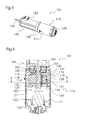
- Fig.3-5 show an alternative embodiment of a drive unit 101.
- this includes in addition to a pyrotechnic drive 110 and a DC motor 140, the side has a connection socket 153 for power supply.
- the said drives 110, 140 act in this case directly on the same shaft 150 a.
- a typical application example of such a configuration is a belt tensioner in which the DC motor 140 provides a reversible drive for potential hazardous situations, while the pyrotechnic drive 110 is provided for accident situations.
- the two drives 110,140 are arranged axially to each other in this embodiment, wherein the entire drive unit 101 has an elongated, approximately cylindrical shape.
- a rotor 113 of the pyrotechnic drive 110 is mounted with a central recess 117 on the shaft 150 and in this case together with this rotatable about an axial direction.
- the rotor 113 is again formed as a plate carrier 114 with inserted into slots 115 fins 116. It is arranged eccentrically in a substantially cylindrical drive chamber 112, which is bounded radially outwardly by an outlet housing 128 in the same manner as in the embodiment shown in FIGS.
- a pressure chamber 120 with a microgas generator 122 arranged therein is not arranged radially but axially relative to the rotor 113.
- the pressure chamber 120 is bounded radially outwards and in the direction of the drive chamber 112 by a pressure housing 127.
- the pressure housing 127 and the axially adjacent outlet housing 128 are arranged axially displaceable within an outer shell housing 111.
- the rotor 113 is rotatably, but axially displaceably connected to the shaft 150.
- a first end member 131 and - in the direction of the pressure chamber 120 - a second end member 132 are arranged, which are each disk-shaped and corresponding to the diameter of the disk carrier 114. However, they are not rotatably connected to the shaft 150 and do not rotate with the rotor 113. They too are axially displaceable.
- pressure chamber 120 and micro gas generator 122 are here substantially identical to the embodiment already discussed. However, in this case, the arrangement and shape of a connecting passage 121 passing through the pressure housing 127 and the outlet housing 128 and connecting the pressure chamber 120 and the driving chamber 112 are different.
- the connecting channel 121 initially leads axially from the pressure chamber in the direction of the drive chamber 112 and then from outside to inside in the radial direction into the drive chamber 112.
- By arrows with dashed lines is in Figure 4 and 5 the path of the gas generated by the micro gas generator 122 indicated, this flows through the connecting channel 121 in the drive chamber 112, the rotor 113 in rotational movement and finally flows out through an outlet openings 118 from.
- the extension of the fins 116 is also supported by the gas pressure in the drive 110 shown here.
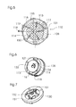
- the second closing element 132 has a passage opening 134 which, when installed, adjoins the passage channel 133.
- an inner portion of the slots 115 can be pressurized with gas pressure to push the fins 116 to the outside.
- connection between these contacts 151 is normally made by a plate spring 152, which on the first end member 131st rests and rotationally fixed in an abutment 130 is inserted, which in turn is connected to the jacket housing 111. That is, by the plate spring 152, the circuit of the DC motor 140 is closed.
- the arrangement of the cross-shaped plate spring 152 in the abutment 130 is in Figure 7 to recognize.
- the interruption of the circuit is achieved by a displacement of parts of the pyrotechnic actuator 110. Due to the axial displaceability of the pressure housing 127, the outlet housing 128, the rotor 113 and the end elements 131, 132, the pressure chamber 120 can expand to a slight extent when pressure is applied to an end face 129 facing the drive chamber 112. In this case, a compression of the plate spring 152, whereby on the one hand a restoring force is given, on the other hand, an interruption of the circuit takes place, since the plate spring 152 is no longer in contact with the contacts 151. After reducing the pressure in the pressure chamber, i. After the operation of the pyrotechnic actuator 110 is completed, the axially displaced elements 113, 127, 128, 131, 132 are pushed back into their original position, whereby the circuit of the DC motor 140 is closed again.
- the pyrotechnic drive 110 shown here has a diameter of about 30 mm and a length of about 53 mm.
- the volume of the pressure chamber 120 is approximately 12 cm 3 .
- an average torque of approximately 1.4 Nm and a speed of 1380 U / s can be made available within the first 50 ms.
- the values mentioned here are in no way restrictive with regard to the invention, but are merely intended to illustrate that a high performance can be achieved with a very small design.
- FIG 8 shows a further embodiment of a drive unit 201 according to the invention, which is provided for a seat adjuster of a motor vehicle.
- the drive unit 201 in turn has only one pyrotechnic drive 210. This is intended to be installed between the body and the seat rail of a motor vehicle (not shown).
- a housing 211 of the drive 210 only partially shown. In fact, this forms, as in the already discussed embodiments, a largely gas-tight jacket for a drive chamber 212, in which a rotor 213 is rotatably mounted.
- the rotor 213 is designed here as an impeller. This is made of a circular disc-shaped sheet-metal disc, wherein wings 214 were formed by partially punching and bending of outer portions of the circular disc.
- the rotor 213 has a central recess 215 with serrated edge.
- the rotor 213 is rotatably connected to a cylindrical sleeve member 216 having an internal thread (not shown).
- the internal thread cooperates with an external thread 237 of a lifting bolt 236, which is guided through the sleeve element 216 and through the central recess 215 of the rotor 213.
- the lifting pin 236 is secured against rotation with the seat rail. Upon rotation of the external thread, an axial displacement of the lifting bolt 236 therefore takes place via the internal thread 237.
Abstract
Description
Die Erfindung betrifft eine Antriebseinheit für ein Sicherheitssystem eines Fahrzeugs sowie ein solches Sicherheitssystem.The invention relates to a drive unit for a safety system of a vehicle and to such a safety system.
Im Fahrzeugbau, insbesondere in Kfz-Bereich, sind verschiedene Sicherheitssysteme bekannt, bei denen im Falle eines Unfalls oder einer Gefahrensituation ein Antrieb auf eine Fahrzeugkomponente einwirkt, um die Sicherheit für die Fahrzeuginsassen zu erhöhen. Hierunter fallen insbesondere Gurtstraffer, bei denen über einen Antrieb der Rückhaltegurt des Fahrers bzw. Beifahrers durch Aufwickeln gestrafft wird, wodurch ein verbesserter Rückhalt für den Insassen gegeben ist. Hierbei sind im Stand der Technik zum einen elektrische Antriebe bekannt, mittels derer es allerdings schwierig ist, ein hinreichendes Drehmoment bei geringer Baugröße aufzubringen. Daneben sind pyrotechnische Antriebe bekannt, die beispielsweise zur Unterstützung ("Boosten") eines Elektroantriebs in Gefahren- oder Unfallsituationen eingesetzt werden. Hierunter fallen Systeme mit Kolben, bei denen die Kolbenbewegung auf einer Zahnstange übertragen wird, die wiederum mit einem Zahnrad zusammenwirkt, durch dessen Drehung der Gurt aufgewickelt wird. Die Flexibilität dieser Systeme ist durch den zumeist geringen Hub des Kolbens begrenzt. Ein weiterer Nachteil besteht in den Reibungsverlusten bei der Umsetzung der linearen Bewegung in eine Drehbewegung. Daneben sind Systeme bekannt, bei denen eine Reihe von Stahlkugeln mittels Gasdruck angetrieben werden, die wiederum ein Flügelrad antreiben, dessen Drehung das Aufwickeln des Gurtes bewirkt. Auch hierbei treten Reibungsverluste auf, zudem zwingen die Forderung nach einem ausreichenden Beschleunigungsweg für die Kugeln einerseits und einer geringen Baugröße andererseits zu Kompromissen.In vehicle construction, in particular in the automotive sector, various safety systems are known in which in the case of an accident or a dangerous situation, a drive acts on a vehicle component in order to increase safety for the vehicle occupants. These include, in particular, belt tensioners in which the restraint belt of the driver or front passenger is tightened by being wound up by means of a drive, whereby an improved support for the occupant is provided. In this case, electric drives are known in the prior art, by means of which, however, it is difficult to apply a sufficient torque with a small size. In addition, pyrotechnic drives are known which are used, for example, to support ("boost") an electric drive in dangerous or accident situations. This includes systems with pistons in which the piston movement is transmitted on a rack, which in turn cooperates with a gear, by the rotation of the belt is wound up. The flexibility of these systems is limited by the usually small stroke of the piston. Another disadvantage is the friction losses in the implementation of the linear movement in a rotary motion. In addition, systems are known in which a number of steel balls are driven by gas pressure, which in turn drive an impeller whose rotation causes the winding of the belt. Here, too, occur friction losses, also force the demand for a sufficient acceleration path for the balls on the one hand and a small size on the other hand to compromise.
Vor diesem Hintergrund ist es Aufgabe der vorliegenden Erfindung, ein effizientes System zum Antrieb eines Sicherheitssystems eines Fahrzeugs, insbesondere eines Gurtstraffers oder eines Sitzverstellers, bereitzustellen.Against this background, it is an object of the present invention to provide an efficient system for driving a safety system of a vehicle, in particular a belt tensioner or a seat adjuster.
Die Aufgabe wird erfindungsgemäß gelöst durch eine Antriebseinheit nach Anspruch 1 sowie durch ein Sicherheitssystem nach Anspruch 14.The object is achieved by a drive unit according to claim 1 and by a security system according to
Die erfindungsgemäße Antriebseinheit für ein Sicherheitssystem eines Fahrzeugs umfasst wenigstens einen pyrotechnischen Antrieb. Wie bereits eingangs erläutert, bezeichnet "Sicherheitssystem" hierbei ein solches System, das im Falle eines Unfalls oder einer Gefahrensituation dafür sorgt, dass wenigstens eine Fahrzeugkomponente bewegt wird, um die Sicherheit für Fahrzeuginsassen zu erhöhen, insbesondere um ein Verletzungsrisiko für diese herabzusetzen. Dies bezieht sich insbesondere auf Gurtstraffer oder Sitzversteller, wobei der pyrotechnische Antrieb in Unfall- oder Gefahrensituationen einen Elektromotor unterstützen kann, daneben sind aber auch weitere Systeme denkbar, bei denen beispielsweise ein Fahrzeugsitz, eine Konsole, ein Bedienelement oder Teile hiervon bewegt werden.The drive unit according to the invention for a safety system of a vehicle comprises at least one pyrotechnic drive. As already explained at the outset, "safety system" here refers to such a system which, in the event of an accident or a dangerous situation, ensures that at least one vehicle component is moved in order to increase safety for vehicle occupants, in particular in order to reduce a risk of injury to them. This refers in particular to belt tensioners or seat adjusters, wherein the pyrotechnic drive can support an electric motor in accident or dangerous situations, but also other systems are conceivable in which, for example, a vehicle seat, a console, an operating element or parts thereof are moved.
Der genannte pyrotechnische Antrieb weist eine in einem Gehäuse ausgebildete Antriebskammer mit einer Austrittsöffnung für Gas auf. Das Gehäuse umschließt hierbei wenigstens die genannte Antriebskammer, kann aber ggf. auch weitere Teile des pyrotechnischen Antriebs umschließen. Abgesehen von der genannten Austrittsöffnung, die dazu ausgelegt ist, dass beim Betrieb durch sie Gas entweicht, - sowie von einer optional vorhandenen Öffnung, durch die Gas einströmt, welche weiter unten diskutiert wird - ist die Antriebskammer bevorzugt gasdicht aufgebaut. Als Materialien für die Konstruktion des Gehäuses bzw. der Kammerwandung kommen verschiedene Materialien, insbesondere Metalle wie Stahl oder hochfeste faserverstärkte Kunststoffe, infrage. Die Kammer kann allerdings innenseitig beispielsweise mit Kunststoff beschichtet sein, um eine geringere Reibung zu gewährleisten. In der Antriebskammer ist ein Rotor angeordnet, der axial drehbar gelagert ist. Der Begriff "axial" ist hierbei nicht dahingehend auszulegen, dass der Rotor oder die Antriebskammer zwangsläufig eine bestimmte (axiale) Symmetrie aufweisen. Vielmehr wird durch die Richtung der Drehachse des Rotors die axiale Richtung festgelegt, wodurch auch die Richtungen "tangential" und "radial" definiert sind.Said pyrotechnic drive has a housing formed in a drive chamber with an outlet for gas. The housing encloses at least the said drive chamber, but may possibly also enclose other parts of the pyrotechnic drive. Apart from the said outlet opening, which is designed so that gas escapes during operation through it, as well as from an optional existing opening through which gas flows, which is discussed below, the drive chamber is preferably gas-tight. As materials for the construction of the housing or the chamber wall, various materials, in particular metals such as steel or high-strength fiber-reinforced plastics, come into question. However, the chamber can be coated on the inside, for example, with plastic to ensure a lower friction. In the drive chamber, a rotor is arranged, which is axially rotatably mounted. The term "axial" here is not to be interpreted as meaning that the rotor or the drive chamber necessarily have a certain (axial) symmetry. Rather, the axial direction is determined by the direction of the axis of rotation of the rotor, whereby the directions "tangential" and "radially" are defined.
Des Weiteren weist der pyrotechnische Antrieb einen pyrotechnischen Gasgenerator auf. Es können hierbei Gasgeneratoren eingesetzt werden, die im Stand der Technik bereits bekannt sind und z.B. im Zusammenwirken mit Kolben oder Stahlkugeln wie geschildert eingesetzt werden. Im Allgemeinen bezeichnet "pyrotechnischer Gasgenerator" hierbei allerdings jede Vorrichtung, in der gezielt eine chemische Reaktion auslösbar ist, die zur Gasentwicklung führt, typischerweise in Form einer Explosion oder eines gezielten Abbrands. In Kombination hiermit können auch Kartuschen mit vorgespanntem Gas verwendete werden, bei denen z.B. ein pyrotechnischer Gasgenerator eine Berstscheibe zerstört und damit den Zustrom von Gas aus der Kartusche zur Antriebseinheit freigibt. Der Gasgenerator dient zum Beaufschlagen des Rotors mit Gasdruck, wodurch der Rotor antreibbar ist. Der Rotor wird hierbei also unmittelbar mit Gasdruck beaufschlagt und dadurch in Drehbewegung versetzt. Es gibt also im Gegensatz zum Stand der Technik keine zwischengeschalteten Elemente, durch die die Drehbewegung erzeugt wird. Hierdurch können zum einen Reibungsverluste minimiert werden, zum anderen ist eine geringere Baugröße möglich. Es ist hierbei also vorgesehen, dass durch ein Auslösen des Gasgenerators ein Gasdruck aufgebaut wird, durch den der Rotor in Drehung versetzt wird, wobei das Gas schließlich durch die Austrittsöffnung entweichen kann. Es können auch mehrere Austrittsöffnung vorhanden sein bzw. die Austrittsöffnung kann Unterteilungen aufweisen. Überhaupt ist im Zusammenhang mit der vorliegenden Erfindung die Angabe "ein(e)", sofern nicht anders angegeben, als "wenigstens ein(e)" zu verstehen.Furthermore, the pyrotechnic drive on a pyrotechnic gas generator. In this case, it is possible to use gas generators which are already known in the prior art and, for example, are used as described in cooperation with pistons or steel balls. In general, however, "pyrotechnic gas generator" here means any device in which a targeted chemical reaction is triggered, which leads to gas evolution, typically in the form of an explosion or a targeted burnup. In combination with this can Also, cartridges are used with biased gas in which, for example, a pyrotechnic gas generator destroys a rupture disc and thus releases the influx of gas from the cartridge to the drive unit. The gas generator is used to pressurize the rotor with gas pressure, whereby the rotor is driven. The rotor is thus directly subjected to gas pressure and thereby set in rotary motion. Thus, in contrast to the prior art, there are no intermediate elements by which the rotational movement is generated. As a result, on the one hand friction losses can be minimized, on the other hand a smaller size is possible. It is thus provided that by triggering the gas generator, a gas pressure is built up by which the rotor is rotated, wherein the gas can finally escape through the outlet opening. There may also be a plurality of outlet opening or the outlet opening may have subdivisions. In general, in the context of the present invention, the term "one (s)", unless otherwise stated, is to be understood as "at least one".
Ein weiterer Vorteil gegenüber bestimmten im Stand der Technik bekannten Lösungen besteht darin, dass die Drehbewegung des Rotors antriebsseitig nur durch die zur Verfügung stehende Gasmenge begrenzt ist, d.h. solange Gasdruck vorhanden ist, kann der Rotor eine Vielzahl von Umdrehungen ausführen. Diese können, falls notwendig, durch eine entsprechende Untersetzung extern reduziert werden. Durch den Einsatz o. g. Gaskartuschen kann die Nutzungsdauer bei Bedarf verlängert werden.Another advantage over certain known in the prior art solutions is that the rotational movement of the rotor on the drive side is limited only by the available amount of gas, i. as long as gas pressure is present, the rotor can make a large number of revolutions. These can, if necessary, be externally reduced by an appropriate reduction ratio. By using o. G. Gas cartridges can extend the useful life if needed.
Wenngleich es denkbar ist, den Gasgenerator unmittelbar in der Antriebskammer anzuordnen, ist es bevorzugt, dass der Gasgenerator an einer Druckkammer angeordnet ist, die mit der Antriebskammer über einen Verbindungskanal verbunden ist, welcher gegenüber der Druckkammer verjüngt ist. Die Anordnung des Gasgenerators ist hierbei derart gewählt, dass freigesetztes Gas zunächst in die genannte Druckkammer strömt. Dies schließt selbstverständlich Bauformen ein, bei denen der Gasgenerator in der genannten Druckkammer angeordnet ist. Er kann aber auch z.B. in eine Wandung der Druckkammer eingelassen sein. Durch den Verbindungskanal strömt das Gas weiter in die Antriebskammer. Hierbei erfüllt der Verbindungskanal zwei Funktionen. Zum einen wird dadurch, dass er gegenüber der Druckkammer verjüngt ist, ein kleinerer Zugangsweg für das Gas geschaffen, wodurch dieses über einen längeren Zeitraum in die Druckkammer strömen kann. Zum anderen ist es durch den Verbindungskanal möglich, das Gas gezielt in einen bestimmten Teil der Antriebskammer zu leiten, wo eine optimale Einwirkung auf den Rotor erfolgt. Eine maximale Querabmessung (z.B. ein Durchmesser) des Verbindungskanals kann hierbei bevorzugt zwischen 1% und 90%, weiter bevorzugt zwischen 5% und 70%, besonders bevorzugt zwischen 10% und 30% einer maximalen Abmessung der Druckkammer betragen. Sowohl die Druckkammer als auch der Verbindungskanal müssen hierbei selbstverständlich stabil genug sein, um den auftretenden Gasdrücken zu widerstehen, weshalb sie beispielsweise innerhalb eines Metallkörpers ausgebildet sein können. Die Dimensionierung der Druckkammer ist vorteilhaft vergleichsweise groß; ihr Volumen kann beispielsweise das 0,5-fache bis 500-fache, bevorzugt das 10-fache bis 100-fache des Volumens der Antriebskammer betragen. Bei Einsatz einer Gaskartusche ist hierbei deren Volumen dem der Druckkammer hinzuzurechnen.Although it is conceivable to arrange the gas generator directly in the drive chamber, it is preferable that the gas generator is arranged on a pressure chamber which is connected to the drive chamber via a connection channel, which is tapered with respect to the pressure chamber. The arrangement of the gas generator is in this case selected such that released gas first flows into said pressure chamber. This of course includes designs in which the gas generator is arranged in said pressure chamber. But it can also be embedded, for example, in a wall of the pressure chamber. Through the connecting channel, the gas flows further into the drive chamber. In this case, the connection channel fulfills two functions. On the one hand, by virtue of the fact that it is tapered with respect to the pressure chamber, a smaller access path for the gas is created, as a result of which it can flow into the pressure chamber over a relatively long period of time. On the other hand, it is possible through the connecting channel to direct the gas targeted into a specific part of the drive chamber, where an optimal action on the rotor takes place. A maximum transverse dimension (eg a diameter) of the connecting channel can hereby preferably be between 1% and 90%, more preferably between 5% and 70%, particularly preferably between 10% and 30% of a maximum dimension of the pressure chamber. Of course, both the pressure chamber and the connecting channel must be stable enough to withstand the occurring gas pressures, which is why they can be formed, for example, within a metal body. The dimensioning of the pressure chamber is advantageously comparatively large; their volume may for example be 0.5 times to 500 times, preferably 10 times to 100 times, the volume of the drive chamber. If a gas cartridge is used, its volume must be added to that of the pressure chamber.
Gemäß einer Ausgestaltung der Erfindung ist der Rotor nach Art eines Lamellenmotors ausgebildet. Solche Motoren sind im Stand der Technik bekannt, insbesondere in Verbindung mit Druckluft als Antriebsmittel. Bei einer typischen Bauform weist hierbei der Rotor einen im Wesentlichen zylindrischen Lamellenträger auf, der mit radial verlaufenden Schlitzen versehen ist, in die Lamellen gesteckt sind. Die Antriebskammer ist ebenfalls zylindrisch ausgebildet, allerdings exzentrisch zum Rotor, so dass dieser an einer Seite nahezu die Wandung der Kammer berührt, während an der gegenüberliegenden Seite ein größerer Abstand besteht. An letzterer Seite befindet sich typischerweise die Austrittsöffnung, während das erzeugte Gas zunächst dem Teil zugeleitet wird, in dem der Abstand zwischen Rotor und Wandung gering ist. Die Lamellen sorgen für eine Abdichtung zwischen Rotor und Wandung, wobei sie typischerweise durch Fliehkräfte nach außen gedrückt werden, wodurch ein zumindest überwiegend gasdichter Abschluss gewährleistet ist. Die Bewegung der Lamellen nach außen kann - insbesondere in der Anfangsphase - unterstützt werden, indem Gas in die Schlitze innenseitig der Lamellen geführt wird und die Lamellen so mit Gasdruck beaufschlagt werden.According to one embodiment of the invention, the rotor is designed in the manner of a disk motor. Such motors are known in the art, especially in connection with compressed air as a drive means. In a typical design, in this case, the rotor has a substantially cylindrical plate carrier, which is provided with radially extending slots, are inserted in the slats. The drive chamber is also cylindrical, but eccentric to the rotor so that it almost touches the wall of the chamber on one side, while at the opposite side there is a greater distance. On the latter side is typically the outlet opening, while the gas generated is first fed to the part in which the distance between the rotor and the wall is small. The lamellae provide a seal between the rotor and the wall, wherein they are typically pressed by centrifugal forces to the outside, whereby an at least predominantly gas-tight closure is ensured. The movement of the slats outward can - especially in the initial phase - are supported by gas is guided in the slots inside the slats and the slats are so pressurized with gas pressure.
In einer alternativen Ausgestaltung ist der Rotor als Flügelrad ausgebildet. Hierbei kann das Flügelrad aus einem einzigen Stück bestehen, z.B. aus einem Metallblech. Es sind zum einen Bauformen denkbar, bei denen das Flügelrad in Richtung seiner Rotationsachse vom Gas angeströmt wird. Dies kann insbesondere bei axialer Anordnung des Gasgenerators und/oder der Druckkammer der Fall sein. Daneben sind auch Bauformen möglich, bei denen das Flügelrad tangential, also senkrecht zur Drehachse, angeströmt wird. Dies ist insbesondere bei radialer Anordnung des Gasgenerators und/oder der Druckkammer denkbar.In an alternative embodiment, the rotor is designed as an impeller. Here, the impeller may consist of a single piece, for example of a metal sheet. There are on the one hand designs conceivable in which the impeller is flown in the direction of its axis of rotation from the gas. This may be the case in particular in the case of an axial arrangement of the gas generator and / or the pressure chamber. In addition, designs are possible in which the impeller is tangential, ie perpendicular to the axis of rotation, is flown. This is conceivable in particular in the case of a radial arrangement of the gas generator and / or the pressure chamber.
Wie bereits dargestellt, ermöglicht die erfindungsgemäße Antriebseinheit eine geringe Baugröße, wodurch sie flexibel einsetzbar ist. Diese Flexibilität lässt sich weiter erhöhen, indem der Gasgenerator und/oder die Druckkammer, sofern diese vorhanden ist, in unterschiedlicher Weise bezüglich des Rotors angeordnet werden. So ist es zum einen denkbar, dass eines der genannten Elemente oder beide axial bezüglich des Rotors angeordnet sind. Hierdurch ergibt sich in Bezug auf die axiale Richtung eine schlanke Bauform.As already shown, the drive unit according to the invention allows a small size, whereby it can be used flexibly. This flexibility can be further increased by the gas generator and / or the pressure chamber, if present, are arranged in different ways with respect to the rotor. Thus, it is conceivable that one of said elements or both are arranged axially with respect to the rotor. This results in a slim design with respect to the axial direction.
Daneben ist es für bestimmte Anwendungen auch sinnvoll, dass der Gasgenerator und/oder die Druckkammer radial bezüglich des Rotors angeordnet sind. Dies ist z.B. dann vorteilhaft, wenn eine Welle, auf die der Rotor einwirkt, durch den pyrotechnischen Antrieb hindurchgeführt werden soll, was bei einer axialen Anordnung kaum möglich ist. Des Weiteren ist diese Anordnung vorteilhaft, wenn bezogen auf die axiale Richtung keine schlanke, sondern eine flache Bauform gewünscht ist.In addition, it is also useful for certain applications that the gas generator and / or the pressure chamber are arranged radially with respect to the rotor. This is e.g. then advantageous if a shaft which is acted upon by the rotor, to be passed through the pyrotechnic drive, which is hardly possible in an axial arrangement. Furthermore, this arrangement is advantageous if, based on the axial direction, no slim, but a flat design is desired.
Falls eine Druckkammer vorhanden ist, an welcher der Gasgenerator angeordnet ist, entspricht die axiale bzw. radiale Anordnung bezüglich des Rotors einer axialen bzw. radialen Anordnung bezüglich der Antriebskammer. In jedem der genannten Fälle ist es bei Vorhandensein eines Verbindungskanals möglich, das austretende Gas denjenigen Teil der Antriebskammer zuzuleiten, in dem eine optimale Beaufschlagung des Rotors erfolgt. Besonders vorteilhaft ist jeweils der Gasgenerator an dem der Antriebskammer bzw. dem Rotor gegenüberliegenden Ende der Druckkammer angeordnet.If a pressure chamber is present on which the gas generator is arranged, the axial or radial arrangement with respect to the rotor corresponds to an axial or radial arrangement with respect to the drive chamber. In each of these cases, in the presence of a connecting channel, it is possible to supply the escaping gas to that part of the drive chamber in which the rotor is optimally loaded. In each case, the gas generator is particularly advantageously arranged on the end of the pressure chamber opposite the drive chamber or the rotor.
Da in der Praxis ein Unfall, der den Einsatz des Sicherheitssystems bedingt, oftmals nicht mit einem Totalschaden des betreffenden Fahrzeugs endet, ist es wünschenswert, eine einfache Wiederverwendbarkeit der Antriebseinheit vorzusehen. Hierbei reicht es in der Regel, den Gasgenerator zu ersetzen, da beim Betrieb die weiteren Bauteile normalerweise allenfalls Gasdruck ausgesetzt sind und somit unbeschädigt bleiben. Daher ist gemäß einer bevorzugten Ausführungsform vorgesehen, dass der Gasgenerator lösbar mit dem Rest des pyrotechnischen Antriebs verbunden ist. Dies kann durch verschiedene Verbindungsarten, die im Stand der Technik bekannt sind, erreicht werden, so z.B. durch Schnappverbindungen oder Schraubverbindungen. Besonders bevorzugt kann hierbei vorgesehen sein, dass der Gasgenerator mit einem Gehäuseteil, der einen Teil der Wandung der Druckkammer bildet, lösbar verbunden ist, und dass dieser Gehäuseteil seinerseits lösbar mit dem Rest des Gehäuses verbunden ist. Hierfür kann insbesondere eine Verbindung mittels eines Bajonettverschlusses vorgesehen sein.In practice, since an accident involving the use of the safety system often does not end in a total loss of the subject vehicle, it is desirable to provide easy reusability of the drive unit. In this case, it is usually sufficient to replace the gas generator, since during operation, the other components are normally exposed to gas pressure at most and thus remain undamaged. Therefore, it is provided according to a preferred embodiment that the gas generator is detachably connected to the rest of the pyrotechnic drive. This can be achieved by various types of connections known in the art, such as by snap connections or screw connections. Particularly preferably, it may be provided that the gas generator with a housing part which forms part of the wall of the pressure chamber, is detachably connected, and that this housing part in turn is releasably connected to the rest of the housing. This can be especially a connection can be provided by means of a bayonet closure.
Gemäß einer Ausgestaltung der Erfindung umfasst die Antriebseinheit einen zweiten Antrieb. Dies kann zum einen bedeuten, dass ein weiterer pyrotechnischer Antrieb vorgesehen ist, der gleichzeitig oder z.B. zeitlich gestaffelt mit dem pyrotechnischen Antrieb zum Einsatz kommt. Zum anderen kann es sich aber um eine andere Antriebsart, wie z.B. einen elektrischen Antrieb, handeln. Die andere Antriebsart kommt normalerweise außerhalb einer Unfallsituation zum Einsatz. Ein Beispiel hierfür wäre ein im Stand der Technik bekannter reversibler Gurtstraffer, der mittels eines elektrischen Antriebes in Gefahrensituationen mit einer geringeren Kraft auf den Gurt einwirkt.According to one embodiment of the invention, the drive unit comprises a second drive. This may mean, on the one hand, that a further pyrotechnic drive is provided, which simultaneously or e.g. staggered in time with the pyrotechnic drive is used. On the other hand, however, it may be another type of drive, such as an electric drive, act. The other type of drive is normally used outside of an accident situation. An example of this would be a known in the art reversible belt tensioner, which acts by means of an electric drive in dangerous situations with a lower force on the belt.
Bei der Kombination zweier Antriebe können insbesondere der pyrotechnische Antrieb und der zweite Antrieb axial zueinander angeordnet sein und auf dieselbe Welle einwirken. Auch dieses ist eine typische Situation bei einem Gurtstraffer, der einen elektrischen und einen pyrotechnischen Antrieb umfasst.In the combination of two drives, in particular the pyrotechnic drive and the second drive can be arranged axially relative to one another and act on the same shaft. This too is a typical situation with a belt tensioner comprising an electric and a pyrotechnic drive.
Ein spezielles Problem ergibt sich, wenn der zweite Antrieb einen Elektromotor umfasst, insbesondere z.B. dann, wenn beide Antriebe auf dieselbe Welle einwirken. Sind die Antriebe in dieser oder in anderer Weise mechanisch aneinander gekoppelt, kann es aufgrund der starken Winkelbeschleunigung durch den pyrotechnischen Antrieb zu Überspannung kommen, wobei der Elektromotor als Generator wirkt. Die Überspannung kann beispielsweise dazu führen, dass die Elektronik des Elektromotors zerstört wird. Um dies zu verhindern, ist in einer bevorzugten Ausgestaltung der Erfindung der pyrotechnische Antrieb dazu ausgebildet, bei Inbetriebnahme einen Schutzschalter des Elektromotors auszulösen. Durch diese Maßnahme können elektronische Bauteile vor auftretenden Spannungsspitzen effektiv geschützt werden. Als Schutzschalter dienen in diesem Zusammenhang insbesondere solche Schalter, durch die ein Stromkreis des Elektromotors getrennt wird und/oder durch die ein alternativer Stromkreis geschlossen wird, um z.B. die Steuerelektronik zu schützen. Hierbei beinhaltet die Formulierung "bei Inbetriebnahme" ausdrücklich auch solche Ausführungsformen, bei denen die Unterbrechung des Stromkreises nicht gleichzeitig mit der Inbetriebnahme (also insbesondere mit dem Auslösen des Gasgenerators) erfolgt, sondern mit einer gewissen Verzögerung; diese kann sich z.B. aufgrund der Trägheit von Bauteilen ergeben, liegt allerdings bevorzugt unter 10 ms, weiter bevorzugt unter 5 ms, besonders bevorzugt unter 2 ms.A special problem arises when the second drive comprises an electric motor, in particular, for example, when both drives act on the same shaft. If the drives are mechanically coupled to one another in this or in another way, overvoltage can occur due to the strong angular acceleration due to the pyrotechnic drive, the electric motor acting as a generator. The overvoltage can, for example, cause the electronics of the electric motor to be destroyed. To prevent this, in a preferred embodiment of the invention, the pyrotechnic drive is designed to trigger a circuit breaker of the electric motor during startup. By this measure, electronic components can be effectively protected from occurring voltage spikes. As a circuit breaker serve in this context, in particular those switches by which a circuit of the electric motor is disconnected and / or closed by an alternative circuit, for example, to protect the control electronics. Here, the phrase "at startup" expressly includes such embodiments in which the interruption of the circuit is not carried out simultaneously with the commissioning (ie in particular with the triggering of the gas generator), but with a certain delay; This can result, for example, due to the inertia of components, but is preferably less than 10 ms, more preferably less than 5 ms, particularly preferably less than 2 ms.
Es ist alternativ zwar denkbar, einen entsprechenden Schutzschalter durch eine übergeordnete Steuerung auszulösen, allerdings ist die direkte Auslösung durch den pyrotechnischen Antrieb besonders wenig störanfällig und ermöglicht einen flexibleren Einsatz ohne die Notwendigkeit zusätzlicher externer Steuerleitungen.Although it is alternatively conceivable to trigger a corresponding circuit breaker by a higher-level control, but the direct triggering by the pyrotechnic drive is particularly susceptible to interference and allows a more flexible use without the need for additional external control lines.
Eine besonders effektive Art, die oben genannte Schutzmaßnahme zu verwirklichen, besteht darin, dass wenigstens ein Teil des pyrotechnischen Antriebs durch Beaufschlagen mit Gasdruck axial und/oder radial verschiebbar ist, wodurch der Schutzschalter ausgelöst wird. Bevorzugt umfasst die Antriebseinheit hierbei ein Rückstellelement zum Rückführen des pyrotechnische Antriebs oder eines Teils desselben in eine Ausgangsposition nach einem Abfallen des Gasdrucks. Hierbei kann die Verschiebung insbesondere entgegen einer Federkraft erfolgen, so dass nach Abbau des Gasdrucks der verschobene Teil des pyrotechnischen Antriebs in seine Ausgangsposition zurückkehrt. Der genannte Teil des Antriebs kann z.B. ein Teil des Gehäuses sein und/oder der Rotor selbst kann zusätzlich zu seiner tangentialen Bewegung eine axiale Verschiebung erfahren. Besonders bevorzugt ist hierbei ein Gehäuse des pyrotechnischen Antriebs wenigstens teilweise in ein stationäres Außengehäuse sowie ein axial verschiebliches Innengehäuse unterteilt. Der sich verschiebende Teil des pyrotechnischen Antriebs kann mit einem Druckschalter zusammenwirken, der für die Unterbrechung des Stromkreises sorgt. Im einfachsten Fall kann auch ein Federelement, entgegen dessen Kraft die Verschiebung erfolgt, einen Teil des Stromkreises bilden. Hierbei erfolgt die Unterbrechung des Stromkreises durch die Verformung des Federelements.A particularly effective way to implement the above-mentioned protective measure is that at least part of the pyrotechnic drive is axially and / or radially displaceable by applying gas pressure, whereby the circuit breaker is triggered. In this case, the drive unit preferably comprises a return element for returning the pyrotechnic drive or a part thereof to an initial position after a drop in the gas pressure. In this case, the displacement can take place, in particular, counter to a spring force, so that, after the gas pressure has been reduced, the displaced part of the pyrotechnic drive returns to its starting position. The said part of the drive can e.g. be part of the housing and / or the rotor itself may experience an axial displacement in addition to its tangential movement. Particularly preferably, a housing of the pyrotechnic drive is at least partially subdivided into a stationary outer housing and an axially displaceable inner housing. The shifting part of the pyrotechnic actuator can interact with a pressure switch that breaks the circuit. In the simplest case, a spring element, against the force of which the displacement takes place, form part of the circuit. In this case, the interruption of the circuit is effected by the deformation of the spring element.
Wie bereits dargestellt wurde, kann die durch den Rotor erzeugte Drehbewegung beispielsweise bei einem Gurtstraffer unmittelbar benutzt werden. Für bestimmte Anwendungen kann aber auch eine Umwandlung der Bewegung vorgesehen werden. Daher umfasst die Antriebseinheit gemäß einer Ausgestaltung der Erfindung ein Getriebe, mit dem wenigstens ein Antrieb zusammenwirkt. Hierbei kann zum einen über eine Kombination von Zahnrädern eine Über- oder Untersetzung erfolgen, es ist aber auch eine Umsetzung in eine lineare Bewegung mittels einer Zahnstange oder ähnlichem denkbar. Auch kann ein Getriebe eine Kombination von zusammenwirkendem Innen- und Außengewinde umfassen, wodurch die Drehbewegung des Rotors in eine lineare Bewegung umgewandelt werden kann. Zwar können durch den Einsatz eines Getriebes wiederum Reibungsverluste auftreten, allerdings ist auch hier der Vorteil gegeben, dass die Bewegung des Rotors antriebsseitig nur durch die zur Verfügung stehende Gasmenge begrenzt ist, nicht jedoch durch den Weg eines Kolben oder die Anzahl zur Verfügung stehender Stahlkugeln. Somit kann z.B. antriebsseitig eine Vielzahl von Umdrehungen erfolgen, die durch eine Untersetzung in eine geringere Umdrehungszahl gewandelt werden, wobei sich allerdings gleichzeitig ein entsprechend höheres Drehmoment ergibt. Wirken zwei Antriebe auf ein Getriebe ein, so können diese beispielsweise unmittelbar über ein und dieselbe Welle einwirken oder aber separat an das Getriebe gekoppelt sein, z.B. über zwei getrennte Wellen. Es kann auch eine Ankopplung mit einer zwischengeschalteten Kupplung (z.B. Fliehkraftkupplung) zur Abkopplung von anderen Bauteilen vorgesehen sein, um eine Beschädigung derselben zu vermeiden. So kann hierdurch z.B. ein Elektromotor auch vor Überspannungen durch Induktion geschützt werden.As already shown, the rotational movement generated by the rotor can be used directly, for example, in a belt tensioner. For certain applications, however, a transformation of the movement can also be provided. Therefore, according to one embodiment of the invention, the drive unit comprises a gear, with which at least one drive cooperates. In this case, on the one hand via a combination of gears over or a reduction done, but it is also a conversion into a linear movement by means of a rack or the like conceivable. Also, a transmission may include a combination of cooperating internal and external threads whereby the rotational movement of the rotor may be converted into a linear motion. Although you can turn by using a gearbox Frictional losses occur, however, there is also the advantage that the movement of the rotor on the drive side is limited only by the available amount of gas, but not by the way a piston or the number of available steel balls. Thus, for example, a plurality of revolutions can be carried out on the drive side, which are converted by a reduction into a lower revolution number, but at the same time results in a correspondingly higher torque. If two drives act on one transmission, they can, for example, act directly on one and the same shaft or be coupled separately to the transmission, eg via two separate shafts. It may also be a coupling with an intermediate clutch (eg centrifugal clutch) for decoupling of other components may be provided to prevent damage to the same. Thus, for example, an electric motor can also be protected against overvoltages by induction.
Die Betriebsparameter des pyrotechnischen Antriebs, insbesondere Drehzahl und Drehmoment, werden durch verschiedene Größen beeinflusst. Hierunter fallen z.B. die vom Gasgenerator freigesetzte Energie und die Dimensionierung von Druckkammer, Verbindungskanal und Rotor. Auch durch die Auslegung des Durchströmquerschnittes zwischen Druckkammer und Lamellenantrieb können die Drehzahl oder ein externes Lastmoment eingestellt werden. Allerdings kann es bei bestimmten Anwendungen sinnvoll sein, den Antrieb gewissermaßen "künstlich" mit einem zusätzlichen Trägheitsmoment zu belasten, wodurch sich dessen Dynamik ebenfalls beeinflussen lässt. Daher umfasst die Antriebseinheit in einer weiteren Ausführungsform ein mit dem pyrotechnischen Antrieb verbundenes Trägheitselement. Ein solches Trägheitselement ist - typischerweise über eine Welle - an den Rotor gekoppelt und hat keine weitere Funktionen außer ein zusätzliches Trägheitsmoment bereitzustellen. Da hierbei ein Material mit hoher Dichte vorteilhaft ist, kann ein solches Trägheitselement insbesondere aus Metall bestehen.The operating parameters of the pyrotechnic drive, in particular speed and torque, are influenced by different sizes. These include e.g. the energy released by the gas generator and the dimensioning of pressure chamber, connecting channel and rotor. Also by the design of the flow area between the pressure chamber and disk drive, the speed or an external load torque can be adjusted. However, in certain applications it may make sense to load the drive "artificially" with an additional moment of inertia, which also influences its dynamics. Therefore, in another embodiment, the drive unit comprises an inertia element connected to the pyrotechnic drive. Such an inertia element is coupled to the rotor, typically via a shaft, and has no other functions other than providing an additional moment of inertia. Since a high-density material is advantageous in this case, such an inertia element may consist in particular of metal.
Gemäß einer Weiterbildung der Erfindung umfasst die Antriebseinheit ein Entriegelungselement, wobei der Gasgenerator dazu ausgebildet ist, auf das Entriegelungselement einzuwirken, um eine Bewegung der Antriebseinheit freizugeben. Ein solches Entriegelungselement kann entweder direkt mit einem Antrieb (z.B. mit dem Rotor), mit einem Getriebe oder sogar mit einer zu bewegenden Fahrzeugkomponente zusammenwirken, um diese zu arretieren. Es kann hierdurch z.B. eine erhöhte Stabilität erreicht werden, solange der pyrotechnische Antrieb nicht ausgelöst wird. In jedem Fall wird die Bewegung der Fahrzeugkomponente durch die Antriebseinheit ver- oder behindert, solange das Entriegelungselement in verriegeltem Zustand ist. Durch die Einwirkung des Gasgenerators erfolgt ein Entriegeln. Der Gasgenerator kann hierbei ggf. das Entriegelungselement selbst mit Gasdruck beaufschlagen oder aber ein mechanisches zwischengeschaltetes Element (z.B. eine Kolben), das seinerseits mechanisch auf das Entriegelungeselement einwirkt. Hierbei kann insbesondere vorgesehen sein, dass erst nach einem Entriegelungsvorgang der Rotor mit Gasdruck beaufschlagt wird.According to one embodiment of the invention, the drive unit comprises an unlocking element, wherein the gas generator is adapted to act on the unlocking element to release a movement of the drive unit. Such an unlocking element can interact either directly with a drive (eg with the rotor), with a gearbox or even with a vehicle component to be moved in order to lock it. It can thus be achieved, for example, increased stability, as long as the pyrotechnic drive is not triggered. In any case, the movement of the vehicle component is obstructed or impeded by the drive unit as long as the unlocking element is in the locked state. By the action the gas generator is unlocked. In this case, the gas generator can optionally apply gas pressure to the unlocking element or a mechanical intermediate element (eg a piston) which in turn mechanically acts on the unlocking element. In this case, it can be provided, in particular, that gas is applied to the rotor only after an unlocking process.
Durch die Erfindung wird des Weiteren ein Sicherheitssystem für ein Fahrzeug bereitgestellt. Dieses Sicherheitssystem umfasst eine erfindungsgemäße Antriebseinheit sowie eine Fahrzeugkomponente, wobei die Antriebseinheit dazu ausgebildet ist, bei einem Unfall oder einer Gefahrensituation die Fahrzeugkomponente zu bewegen, um ein Verletzungsrisiko für Insassen zu verringern. Als Fahrzeuge kommen hier insbesondere Kraftfahrzeuge wie Pkw oder Lkw in Frage. Die Fahrzeugkomponente kann hierbei insbesondere ein Aufwickler eines Sicherheitsgurtes sein. Daneben kann es sich aber auch, wie bereits erwähnt, um einen Fahrzeugsitz, eine Konsole, ein Bedienelement, Teile hiervon oder anderes handeln.The invention further provides a security system for a vehicle. This safety system comprises a drive unit according to the invention and a vehicle component, wherein the drive unit is designed to move the vehicle component in the event of an accident or a dangerous situation in order to reduce a risk of injury to occupants. Vehicles such as cars or trucks come into question here in particular as vehicles. In this case, the vehicle component may in particular be a rewinder of a safety belt. In addition, however, it may also be, as already mentioned, a vehicle seat, a console, an operating element, parts thereof or else.
Details der Erfindungen werden im Folgenden anhand von Ausführungsbeispielen mit Bezug auf die Figuren erläutert. Hierbei zeigt
- Fig.1
- eine perspektivische Darstellung einer ersten Ausführungsform einer erfindungsgemäßen Antriebseinheit;
- Fig.2
- eine Schnittdarstellung der Antriebseinheit aus
Fig.1 ; - Fig.3
- eine perspektivische Darstellung einer zweiten Ausführungsform einer erfindungsgemäßen Antriebseinheit;
- Fig.4
- eine Schnittdarstellung der Antriebseinheit aus
Fig.3 ; - Fig.5
- eine Schnittdarstellung gemäß der Linie A-A aus
Fig.4 ; - Fig.6
- eine perspektivische Darstellung eines Gehäuseteils der Antriebseinheit aus
Fig.3 mit einem darin angeordneten Rotor; - Fig.7
- eine perspektivische Darstellung eines Gehäuseteils der Antriebseinheit aus
Fig.3 mit Elementen eines Schutzschalters; - Fig.8
- eine perspektivische Darstellung einer dritten Ausführungsform einer erfindungsgemäßen Antriebseinheit;
- Fig.9
- eine perspektivische Darstellung des Rotors der Antriebseinheit aus
Fig.8 ; - Fig.10
- eine Schnittdarstellung der Antriebseinheit aus
Fig.8 ;
- Fig.1
- a perspective view of a first embodiment of a drive unit according to the invention;
- Fig.2
- a sectional view of the drive unit
Fig.1 ; - Figure 3
- a perspective view of a second embodiment of a drive unit according to the invention;
- Figure 4
- a sectional view of the drive unit
Figure 3 ; - Figure 5
- a sectional view along the line AA
Figure 4 ; - Figure 6
- a perspective view of a housing part of the drive unit
Figure 3 with a rotor disposed therein; - Figure 7
- a perspective view of a housing part of the drive unit
Figure 3 with elements of a circuit breaker; - Figure 8
- a perspective view of a third embodiment of a drive unit according to the invention;
- Figure 9
- a perspective view of the rotor of the drive unit
Figure 8 ; - Figure 10
- a sectional view of the drive unit
Figure 8 ;
In
Der innere Aufbau des Antriebs 10 wird nunmehr mit Bezug auf die Schnittdarstellung in
Vorliegend arbeitet der Antrieb 10 nach dem Prinzip eines Lamellenmotors. Hierbei ist, wie aus
Über diesen Verbindungskanal 21 steht die Antriebskammer 12 mit einer Druckkammer 20 in Verbindung. Im vorliegenden Fall sind sowohl der Verbindungskanal 21 als auch die Druckkammer 20 im wesentlichen zylindrisch aufgebaut, wobei allerdings die Querabmessung des Verbindungskanals 21 nur ungefähr ein Fünftel derjenigen der Druckkammer 20 beträgt. Der Verschlussdeckel 24 bildet hierbei einen stirnseitigen Abschluss der Druckkammer 20. Innerhalb der Druckkammer 20 ist ein Mikrogasgenerator 22 angeordnet, der über einen Schnappverschluss 25 mit dem Verschlussdeckel 24 verbunden ist. Darüber hinaus ist ein zweiter, kleinerer Verbindungskanal (nicht dargestellt) vorhanden, der die Druckkammer 20 mit einem Teil der Antriebskammer 12 verbindet, der an die (in radialer Richtung) inneren Enden der Schlitze 15 des Rotors 13 angrenzt. Hierüber können diese Bereiche mit Gasdruck beaufschlagt werden, um die Lamellen 16 aktiv nach außen zu drücken.About this
Der Mikrogasgenerator 22 kann in bekannter Weise elektrisch gezündet werden, z.B. über die Airbagsteuerung eines Fahrzeugs. Geschieht dies, so baut sich aufgrund der Gasentwicklung innerhalb der Druckkammer 20 ein hoher Gasdruck auf. Die entstehende Druckwelle erreicht über den Verbindungskanal 21 die Arbeitskammer 12 und beginnt auf dem Weg zu den Austrittsöffnungen 18,19 den Rotor 13 anzutreiben. Nach einer kurzen Anlaufphase, die im Bereich von wenigen Millisekunden, typischerweise sogar unter 1 Millisekunde, liegt, werden hierbei aufgrund der Fliehkräfte sowie durch den Druck des über den zweiten Verbindungskanal hinter die Lamellen 16 geführten Gases die Lamellen 16 in den Schlitzen 15 nach außen zur Wandung der Antriebskammer 12 gedrückt, wodurch ein im wesentlichen gasdichter Abschluss entsteht. Dieser Zustand ist in
Bei dem in
Wie aus den Schnittdarstellungen gemäß
Aufbau und Funktionsweise von Druckkammer 120 und Mikrogasgenerator 122 sind hier im Wesentlichen identisch zu dem bereits diskutierten Ausführungsbeispiel. Allerdings unterscheiden sich in diesem Fall Anordnung und Form eines das Druckgehäuse 127 sowie das Auslassgehäuse 128 durchlaufenden Verbindungskanals 121, der die Druckkammer 120 sowie die Antriebskammer 112 verbindet. Der Verbindungskanal 121 führt zunächst axial von der Druckkammer in Richtung der Antriebskammer 112 und dann von außen nach innen in radialer Richtung in die Antriebskammer 112 hinein. Durch Pfeile mit gestrichelten Linien ist in
Wie bereits beim vorigen Ausführungsbeispiel erwähnt, wird das Ausfahren der Lamellen 116 auch bei dem hier dargestellten Antrieb 110 durch Gasdruck unterstützt. Zu diesem Zweck führt ein Durchlasskanal 133 sehr geringen Querschnitts von der Druckkammer bis zum zweiten Abschlusselement 132. Wie aus
Da bei dieser gezeigten Antriebseinheit 101 der pyrotechnische Antrieb 110 und der Gleichstrommotor 140 über die Welle 150 mechanisch aneinander gekoppelt sind, könnten die beim Einsatz des pyrotechnischen Antriebs 110 auftretenden hohen Drehmomente und Drehzahlen zu Überspannungen im Elektromotor 140 führen. Hierdurch könnte eine (nicht dargestellte) Steuerelektronik des Gleichstrommotors 140 bzw. der Motor 140 selbst beschädigt oder zerstört werden. Um dies zu vermeiden, ist vorgesehen, dass beim Betrieb des pyrotechnischen Antriebs 110 der Stromkreis des Gleichstrommotors 140 unterbrochen wird. Hierzu sind zum einen zwei Kontakte 151, die einen Teil des Stromkreises bilden, in Richtung des pyrotechnischen Antriebs 110 aus dem Elektromotor 140 herausgeführt. Die Verbindung zwischen diesen Kontakten 151 wird im Normalfall durch eine Tellerfeder 152 hergestellt, die auf dem ersten Abschlusselement 131 aufliegt und drehfest in ein Widerlager 130 eingesetzt ist, das seinerseits mit dem Mantelgehäuse 111 verbunden ist. D.h. durch die Tellerfeder 152 ist der Stromkreis des Gleichstrommotors 140 geschlossen. Die Anordnung der kreuzartig ausgebildeten Tellerfeder 152 im Widerlager 130 ist in
Die Unterbrechung des Stromkreises wird durch eine Verschiebung von Teilen des pyrotechnischen Antriebs 110 erreicht. Durch die axiale Verschieblichkeit des Druckgehäuses 127, des Auslassgehäuses 128, des Rotors 113 sowie der Abschlusselemente 131, 132 kann die Druckkammer 120 unter Druckbeaufschlagung einer der Antriebskammer 112 zugewandten Stirnseite 129 in geringem Maße expandieren. Hierbei erfolgt eine Kompression der Tellerfeder 152, wodurch zum einen eine Rückstellkraft gegeben ist, zum anderen eine Unterbrechung des Stromkreises erfolgt, da die Tellerfeder 152 nicht mehr mit den Kontakten 151 in Verbindung steht. Nach dem Abbau des Drucks in der Druckkammer, d.h. nachdem der Betrieb des pyrotechnischen Antriebs 110 beendet ist, werden die axial verschobene Elemente 113, 127, 128, 131, 132 wieder in ihre Ausgangsposition zurückgeschoben, wodurch der Stromkreis des Gleichstrommotors 140 wieder geschlossen wird.The interruption of the circuit is achieved by a displacement of parts of the
Der hier gezeigte pyrotechnische Antrieb 110 weist einen Durchmesser von ca. 30 mm und eine Länge von ca. 53mm auf. Das Volumen der Druckkammer 120 beträgt hierbei ca. 12 cm3. Mit einer Ladung des Mikrogasgenerators 122 von 400 mg können hierbei innerhalb der ersten 50 ms ein mittleres Drehmoment von ca. 1,4 Nm sowie eine Drehzahl von 1380 U/s zur Verfügung gestellt werden. Die hier genannten Werte sind in keiner Weise einschränkend hinsichtlich der Erfindung auszulegen, sondern sollen lediglich illustrieren, dass bei sehr kleiner Bauform eine hohe Leistungsfähigkeit erreicht werden kann.The
Wie insbesondere aus der perspektivischen Darstellung desselben in
Bei dem in
- 11
- Antriebseinheitdrive unit
- 1010
- pyrotechnischer Antriebpyrotechnic drive
- 1111
- Gehäusecasing
- 1212
- Antriebskammerdrive chamber
- 1313
- Rotorrotor
- 1414
- Lamellenträgerplate carrier
- 1515
- Schlitzslot
- 1616
- Lamellelamella
- 1717
- Ausnehmungrecess
- 1818
- erste Gasaustrittsöffnungfirst gas outlet opening
- 1919
- zweite Gasaustrittsöffnungsecond gas outlet opening
- 2020
- Druckkammerpressure chamber
- 2121
- Verbindungskanalconnecting channel
- 2222
- MikrogasgeneratorMicro gas generator
- 2323
- Bajonettverschlussbayonet catch
- 2424
- Verschlussdeckelcap
- 2525
- Schnappverschlusssnap lock
- 2626
- Öffnungopening
- 101101
- Antriebseinheitdrive unit
- 110110
- pyrotechnischer Antriebpyrotechnic drive
- 111111
- Mantelgehäusecover housing
- 112112
- Antriebskammerdrive chamber
- 113113
- Rotorrotor
- 114114
- Lamellenträgerplate carrier
- 115115
- Schlitzslot
- 116116
- Lamellelamella
- 117117
- Ausnehmungrecess
- 118118
- Austrittsöffnungoutlet opening
- 120120
- Druckkammerpressure chamber
- 121121
- Verbindungskanalconnecting channel
- 122122
- MikrogasgeneratorMicro gas generator
- 127127
- Druckgehäusepressure housing
- 128128
- Auslassgehäuseoutlet housing
- 129129
- Stirnseitefront
- 130130
- Widerlagerabutment
- 131131
- erstes Abschlusselementfirst end element
- 132132
- zweites Abschlusselementsecond end element
- 133133
- DurchlasskanalPassageway
- 134134
- DurchlassöffnungPort
- 140140
- GleichstrommotorDC motor
- 150150
- Wellewave
- 151151
- Kontaktecontacts
- 152152
- TellerfederBelleville spring
- 153153
- Anschlussbuchsesocket
- 201201
- Antriebseinheitdrive unit
- 210210
- pyrotechnischer Antriebpyrotechnic drive
- 211211
- Gehäusecasing
- 212212
- Antriebskammerdrive chamber
- 213213
- Rotorrotor
- 214214
- Flügelwing
- 215215
- Ausnehmungrecess
- 216216
- Manschettenelementcollar member
- 218218
- Austrittsöffnungoutlet opening
- 122122
- MikrogasgeneratorMicro gas generator
- 234234
- Kolbenpiston
- 235235
- EntriegelungsschlittenEntriegelungsschlitten
- 236236
- Hubbolzenlifting bolts
- 237237
- Außengewindeexternal thread
- 238238
- Spiralfederspiral spring
Claims (14)
Priority Applications (2)
| Application Number | Priority Date | Filing Date | Title |
|---|---|---|---|
| EP12007233.5A EP2722239B1 (en) | 2012-10-19 | 2012-10-19 | Drive unit for a safety system of a vehicle |
| EP20130179282 EP2684748B1 (en) | 2012-10-19 | 2013-08-05 | Activation unit for a securing system of a motor vehicle |
Applications Claiming Priority (1)
| Application Number | Priority Date | Filing Date | Title |
|---|---|---|---|
| EP12007233.5A EP2722239B1 (en) | 2012-10-19 | 2012-10-19 | Drive unit for a safety system of a vehicle |
Publications (2)
| Publication Number | Publication Date |
|---|---|
| EP2722239A1 true EP2722239A1 (en) | 2014-04-23 |
| EP2722239B1 EP2722239B1 (en) | 2015-04-01 |
Family
ID=47216006
Family Applications (1)
| Application Number | Title | Priority Date | Filing Date |
|---|---|---|---|
| EP12007233.5A Active EP2722239B1 (en) | 2012-10-19 | 2012-10-19 | Drive unit for a safety system of a vehicle |
Country Status (1)
| Country | Link |
|---|---|
| EP (1) | EP2722239B1 (en) |
Citations (3)
| Publication number | Priority date | Publication date | Assignee | Title |
|---|---|---|---|---|
| DE2814487A1 (en) * | 1978-04-04 | 1979-10-11 | Repa Feinstanzwerk Gmbh | BACKSTRAMMER WITH PYROTECHNICAL DRIVE FOR SEAT BELT WRAPPING MACHINE |
| DE3606021A1 (en) * | 1986-02-25 | 1987-08-27 | Ernst Hans Hellmut | Rotary belt tightener for safety belts |
| GB2314755A (en) * | 1996-07-05 | 1998-01-14 | Autoliv Dev | Safety belt pretensioner with energy absorbing means |
Family Cites Families (3)
| Publication number | Priority date | Publication date | Assignee | Title |
|---|---|---|---|---|
| DE19614997A1 (en) * | 1996-04-16 | 1997-10-23 | Hs Tech & Design | Roll-up device for vehicle safety belt |
| DE29609691U1 (en) * | 1996-05-31 | 1996-10-17 | Foehl Artur | Pyrotechnic drive device for a belt tensioner |
| JPH10238216A (en) * | 1996-12-27 | 1998-09-08 | Nippon Kuatsu Syst Kk | Door glass opening device |
-
2012
- 2012-10-19 EP EP12007233.5A patent/EP2722239B1/en active Active
Patent Citations (3)
| Publication number | Priority date | Publication date | Assignee | Title |
|---|---|---|---|---|
| DE2814487A1 (en) * | 1978-04-04 | 1979-10-11 | Repa Feinstanzwerk Gmbh | BACKSTRAMMER WITH PYROTECHNICAL DRIVE FOR SEAT BELT WRAPPING MACHINE |
| DE3606021A1 (en) * | 1986-02-25 | 1987-08-27 | Ernst Hans Hellmut | Rotary belt tightener for safety belts |
| GB2314755A (en) * | 1996-07-05 | 1998-01-14 | Autoliv Dev | Safety belt pretensioner with energy absorbing means |
Also Published As
| Publication number | Publication date |
|---|---|
| EP2722239B1 (en) | 2015-04-01 |
Similar Documents
| Publication | Publication Date | Title |
|---|---|---|
| EP3268260B1 (en) | Steering column for a motor vehicle | |
| DE102016214709A1 (en) | Steering column for a motor vehicle | |
| EP3655274B1 (en) | Hybrid module | |
| WO1997049583A1 (en) | Safety-belt reel with adjustable force limiter | |
| EP3939839B1 (en) | Belt retractor with decoupling device comprising force limiting means | |
| WO2007068452A1 (en) | Belt tensioner for a seatbelt system | |
| DE102011008405A1 (en) | Belt retractor with a speed-controlled force limiting device | |
| EP3665063B1 (en) | Steering column for a motor vehicle | |
| WO2015055570A1 (en) | Force-limiting device for a seat belt system | |
| DE102011101517B4 (en) | Force limiting device for a motor vehicle and belt retractor | |
| EP3472023B1 (en) | Steering column for a motor vehicle | |
| EP3523096B1 (en) | Working tool | |
| DE102010026285A1 (en) | Force limiting device for a motor vehicle | |
| DE102011101481B4 (en) | Belt retractor with a speed-controlled force limiting device | |
| EP1525123B1 (en) | Belt retractor/belt tensioner combination comprising a belt shaft-integrated tensioning drive | |
| DE102011101518B4 (en) | Force limiting device for a motor vehicle and belt retractor | |
| DE102014207297A1 (en) | Belt retractor for a seat belt device | |
| DE4223469A1 (en) | DEVICE FOR PRELOADING A VEHICLE SEAT RESTRAINT | |
| DE102018208535A1 (en) | Energy absorption device for a steering column, steering column and a method for operating a steering column | |
| EP2722239B1 (en) | Drive unit for a safety system of a vehicle | |
| EP2467611B1 (en) | Radially acting rotational stop | |
| EP3123048B1 (en) | Path-controlled adjusting device for a friction clutch | |
| EP3805054A1 (en) | Electric motor unit for a reversible belt tensioner and method for operating a belt tensioner | |
| DE102006002756B4 (en) | driving device | |
| DE102013217236B4 (en) | Belt retractor for a safety belt in a motor vehicle |
Legal Events
| Date | Code | Title | Description |
|---|---|---|---|
| PUAI | Public reference made under article 153(3) epc to a published international application that has entered the european phase |
Free format text: ORIGINAL CODE: 0009012 |
|
| AK | Designated contracting states |
Kind code of ref document: A1 Designated state(s): AL AT BE BG CH CY CZ DE DK EE ES FI FR GB GR HR HU IE IS IT LI LT LU LV MC MK MT NL NO PL PT RO RS SE SI SK SM TR |
|
| AX | Request for extension of the european patent |
Extension state: BA ME |
|
| 17P | Request for examination filed |
Effective date: 20141006 |
|
| RBV | Designated contracting states (corrected) |
Designated state(s): AL AT BE BG CH CY CZ DE DK EE ES FI FR GB GR HR HU IE IS IT LI LT LU LV MC MK MT NL NO PL PT RO RS SE SI SK SM TR |
|
| GRAP | Despatch of communication of intention to grant a patent |
Free format text: ORIGINAL CODE: EPIDOSNIGR1 |
|
| INTG | Intention to grant announced |
Effective date: 20141219 |
|
| GRAS | Grant fee paid |
Free format text: ORIGINAL CODE: EPIDOSNIGR3 |
|
| GRAA | (expected) grant |
Free format text: ORIGINAL CODE: 0009210 |
|
| AK | Designated contracting states |
Kind code of ref document: B1 Designated state(s): AL AT BE BG CH CY CZ DE DK EE ES FI FR GB GR HR HU IE IS IT LI LT LU LV MC MK MT NL NO PL PT RO RS SE SI SK SM TR |
|
| REG | Reference to a national code |
Ref country code: GB Ref legal event code: FG4D Free format text: NOT ENGLISH |
|
| REG | Reference to a national code |
Ref country code: CH Ref legal event code: EP |
|
| REG | Reference to a national code |
Ref country code: IE Ref legal event code: FG4D Free format text: LANGUAGE OF EP DOCUMENT: GERMAN |
|
| REG | Reference to a national code |
Ref country code: AT Ref legal event code: REF Ref document number: 718876 Country of ref document: AT Kind code of ref document: T Effective date: 20150515 |
|
| REG | Reference to a national code |
Ref country code: DE Ref legal event code: R096 Ref document number: 502012002666 Country of ref document: DE Effective date: 20150521 |
|
| REG | Reference to a national code |
Ref country code: NL Ref legal event code: VDEP Effective date: 20150401 |
|
| REG | Reference to a national code |
Ref country code: LT Ref legal event code: MG4D |
|
| PG25 | Lapsed in a contracting state [announced via postgrant information from national office to epo] |
Ref country code: NL Free format text: LAPSE BECAUSE OF FAILURE TO SUBMIT A TRANSLATION OF THE DESCRIPTION OR TO PAY THE FEE WITHIN THE PRESCRIBED TIME-LIMIT Effective date: 20150401 |
|
| PG25 | Lapsed in a contracting state [announced via postgrant information from national office to epo] |
Ref country code: CZ Free format text: LAPSE BECAUSE OF FAILURE TO SUBMIT A TRANSLATION OF THE DESCRIPTION OR TO PAY THE FEE WITHIN THE PRESCRIBED TIME-LIMIT Effective date: 20150401 Ref country code: NO Free format text: LAPSE BECAUSE OF FAILURE TO SUBMIT A TRANSLATION OF THE DESCRIPTION OR TO PAY THE FEE WITHIN THE PRESCRIBED TIME-LIMIT Effective date: 20150701 Ref country code: PT Free format text: LAPSE BECAUSE OF FAILURE TO SUBMIT A TRANSLATION OF THE DESCRIPTION OR TO PAY THE FEE WITHIN THE PRESCRIBED TIME-LIMIT Effective date: 20150803 Ref country code: HR Free format text: LAPSE BECAUSE OF FAILURE TO SUBMIT A TRANSLATION OF THE DESCRIPTION OR TO PAY THE FEE WITHIN THE PRESCRIBED TIME-LIMIT Effective date: 20150401 Ref country code: ES Free format text: LAPSE BECAUSE OF FAILURE TO SUBMIT A TRANSLATION OF THE DESCRIPTION OR TO PAY THE FEE WITHIN THE PRESCRIBED TIME-LIMIT Effective date: 20150401 Ref country code: LT Free format text: LAPSE BECAUSE OF FAILURE TO SUBMIT A TRANSLATION OF THE DESCRIPTION OR TO PAY THE FEE WITHIN THE PRESCRIBED TIME-LIMIT Effective date: 20150401 Ref country code: FI Free format text: LAPSE BECAUSE OF FAILURE TO SUBMIT A TRANSLATION OF THE DESCRIPTION OR TO PAY THE FEE WITHIN THE PRESCRIBED TIME-LIMIT Effective date: 20150401 |
|
| PG25 | Lapsed in a contracting state [announced via postgrant information from national office to epo] |
Ref country code: IS Free format text: LAPSE BECAUSE OF FAILURE TO SUBMIT A TRANSLATION OF THE DESCRIPTION OR TO PAY THE FEE WITHIN THE PRESCRIBED TIME-LIMIT Effective date: 20150801 Ref country code: RS Free format text: LAPSE BECAUSE OF FAILURE TO SUBMIT A TRANSLATION OF THE DESCRIPTION OR TO PAY THE FEE WITHIN THE PRESCRIBED TIME-LIMIT Effective date: 20150401 Ref country code: LV Free format text: LAPSE BECAUSE OF FAILURE TO SUBMIT A TRANSLATION OF THE DESCRIPTION OR TO PAY THE FEE WITHIN THE PRESCRIBED TIME-LIMIT Effective date: 20150401 Ref country code: GR Free format text: LAPSE BECAUSE OF FAILURE TO SUBMIT A TRANSLATION OF THE DESCRIPTION OR TO PAY THE FEE WITHIN THE PRESCRIBED TIME-LIMIT Effective date: 20150702 |
|
| REG | Reference to a national code |
Ref country code: DE Ref legal event code: R097 Ref document number: 502012002666 Country of ref document: DE |
|
| PG25 | Lapsed in a contracting state [announced via postgrant information from national office to epo] |
Ref country code: DK Free format text: LAPSE BECAUSE OF FAILURE TO SUBMIT A TRANSLATION OF THE DESCRIPTION OR TO PAY THE FEE WITHIN THE PRESCRIBED TIME-LIMIT Effective date: 20150401 Ref country code: EE Free format text: LAPSE BECAUSE OF FAILURE TO SUBMIT A TRANSLATION OF THE DESCRIPTION OR TO PAY THE FEE WITHIN THE PRESCRIBED TIME-LIMIT Effective date: 20150401 |
|
| PLBE | No opposition filed within time limit |
Free format text: ORIGINAL CODE: 0009261 |
|
| STAA | Information on the status of an ep patent application or granted ep patent |
Free format text: STATUS: NO OPPOSITION FILED WITHIN TIME LIMIT |
|
| PG25 | Lapsed in a contracting state [announced via postgrant information from national office to epo] |
Ref country code: SK Free format text: LAPSE BECAUSE OF FAILURE TO SUBMIT A TRANSLATION OF THE DESCRIPTION OR TO PAY THE FEE WITHIN THE PRESCRIBED TIME-LIMIT Effective date: 20150401 Ref country code: RO Free format text: LAPSE BECAUSE OF NON-PAYMENT OF DUE FEES Effective date: 20150401 Ref country code: PL Free format text: LAPSE BECAUSE OF FAILURE TO SUBMIT A TRANSLATION OF THE DESCRIPTION OR TO PAY THE FEE WITHIN THE PRESCRIBED TIME-LIMIT Effective date: 20150401 |
|
| 26N | No opposition filed |
Effective date: 20160105 |
|
| PG25 | Lapsed in a contracting state [announced via postgrant information from national office to epo] |
Ref country code: IT Free format text: LAPSE BECAUSE OF FAILURE TO SUBMIT A TRANSLATION OF THE DESCRIPTION OR TO PAY THE FEE WITHIN THE PRESCRIBED TIME-LIMIT Effective date: 20150401 |
|
| PG25 | Lapsed in a contracting state [announced via postgrant information from national office to epo] |
Ref country code: LU Free format text: LAPSE BECAUSE OF FAILURE TO SUBMIT A TRANSLATION OF THE DESCRIPTION OR TO PAY THE FEE WITHIN THE PRESCRIBED TIME-LIMIT Effective date: 20151019 Ref country code: SI Free format text: LAPSE BECAUSE OF FAILURE TO SUBMIT A TRANSLATION OF THE DESCRIPTION OR TO PAY THE FEE WITHIN THE PRESCRIBED TIME-LIMIT Effective date: 20150401 |
|
| REG | Reference to a national code |
Ref country code: CH Ref legal event code: PL |
|
| PG25 | Lapsed in a contracting state [announced via postgrant information from national office to epo] |
Ref country code: MC Free format text: LAPSE BECAUSE OF FAILURE TO SUBMIT A TRANSLATION OF THE DESCRIPTION OR TO PAY THE FEE WITHIN THE PRESCRIBED TIME-LIMIT Effective date: 20150401 |
|
| REG | Reference to a national code |
Ref country code: IE Ref legal event code: MM4A |
|
| PG25 | Lapsed in a contracting state [announced via postgrant information from national office to epo] |
Ref country code: LI Free format text: LAPSE BECAUSE OF NON-PAYMENT OF DUE FEES Effective date: 20151031 Ref country code: CH Free format text: LAPSE BECAUSE OF NON-PAYMENT OF DUE FEES Effective date: 20151031 |
|
| REG | Reference to a national code |
Ref country code: FR Ref legal event code: ST Effective date: 20160630 |
|
| PG25 | Lapsed in a contracting state [announced via postgrant information from national office to epo] |
Ref country code: FR Free format text: LAPSE BECAUSE OF NON-PAYMENT OF DUE FEES Effective date: 20151102 |
|
| PG25 | Lapsed in a contracting state [announced via postgrant information from national office to epo] |
Ref country code: IE Free format text: LAPSE BECAUSE OF NON-PAYMENT OF DUE FEES Effective date: 20151019 |
|
| PG25 | Lapsed in a contracting state [announced via postgrant information from national office to epo] |
Ref country code: SM Free format text: LAPSE BECAUSE OF FAILURE TO SUBMIT A TRANSLATION OF THE DESCRIPTION OR TO PAY THE FEE WITHIN THE PRESCRIBED TIME-LIMIT Effective date: 20150401 Ref country code: BG Free format text: LAPSE BECAUSE OF FAILURE TO SUBMIT A TRANSLATION OF THE DESCRIPTION OR TO PAY THE FEE WITHIN THE PRESCRIBED TIME-LIMIT Effective date: 20150401 Ref country code: HU Free format text: LAPSE BECAUSE OF FAILURE TO SUBMIT A TRANSLATION OF THE DESCRIPTION OR TO PAY THE FEE WITHIN THE PRESCRIBED TIME-LIMIT; INVALID AB INITIO Effective date: 20121019 |
|
| GBPC | Gb: european patent ceased through non-payment of renewal fee |
Effective date: 20161019 |
|
| PG25 | Lapsed in a contracting state [announced via postgrant information from national office to epo] |
Ref country code: CY Free format text: LAPSE BECAUSE OF FAILURE TO SUBMIT A TRANSLATION OF THE DESCRIPTION OR TO PAY THE FEE WITHIN THE PRESCRIBED TIME-LIMIT Effective date: 20150401 Ref country code: SE Free format text: LAPSE BECAUSE OF FAILURE TO SUBMIT A TRANSLATION OF THE DESCRIPTION OR TO PAY THE FEE WITHIN THE PRESCRIBED TIME-LIMIT Effective date: 20150401 |
|
| PG25 | Lapsed in a contracting state [announced via postgrant information from national office to epo] |
Ref country code: GB Free format text: LAPSE BECAUSE OF NON-PAYMENT OF DUE FEES Effective date: 20161019 Ref country code: BE Free format text: LAPSE BECAUSE OF NON-PAYMENT OF DUE FEES Effective date: 20151031 |
|
| PG25 | Lapsed in a contracting state [announced via postgrant information from national office to epo] |
Ref country code: MT Free format text: LAPSE BECAUSE OF FAILURE TO SUBMIT A TRANSLATION OF THE DESCRIPTION OR TO PAY THE FEE WITHIN THE PRESCRIBED TIME-LIMIT Effective date: 20150401 |
|
| PG25 | Lapsed in a contracting state [announced via postgrant information from national office to epo] |
Ref country code: MK Free format text: LAPSE BECAUSE OF FAILURE TO SUBMIT A TRANSLATION OF THE DESCRIPTION OR TO PAY THE FEE WITHIN THE PRESCRIBED TIME-LIMIT Effective date: 20150401 |
|
| PG25 | Lapsed in a contracting state [announced via postgrant information from national office to epo] |
Ref country code: TR Free format text: LAPSE BECAUSE OF FAILURE TO SUBMIT A TRANSLATION OF THE DESCRIPTION OR TO PAY THE FEE WITHIN THE PRESCRIBED TIME-LIMIT Effective date: 20150401 Ref country code: AL Free format text: LAPSE BECAUSE OF FAILURE TO SUBMIT A TRANSLATION OF THE DESCRIPTION OR TO PAY THE FEE WITHIN THE PRESCRIBED TIME-LIMIT Effective date: 20150401 |
|
| REG | Reference to a national code |
Ref country code: AT Ref legal event code: MM01 Ref document number: 718876 Country of ref document: AT Kind code of ref document: T Effective date: 20171019 |
|
| PG25 | Lapsed in a contracting state [announced via postgrant information from national office to epo] |
Ref country code: AT Free format text: LAPSE BECAUSE OF NON-PAYMENT OF DUE FEES Effective date: 20171019 |
|
| P01 | Opt-out of the competence of the unified patent court (upc) registered |
Effective date: 20230531 |
|
| PGFP | Annual fee paid to national office [announced via postgrant information from national office to epo] |
Ref country code: DE Payment date: 20230929 Year of fee payment: 12 |