EP2721373B1 - Verfahren zur kartendatenverarbeitung für industriefahrzeugnavigation - Google Patents
Verfahren zur kartendatenverarbeitung für industriefahrzeugnavigation Download PDFInfo
- Publication number
- EP2721373B1 EP2721373B1 EP12741123.9A EP12741123A EP2721373B1 EP 2721373 B1 EP2721373 B1 EP 2721373B1 EP 12741123 A EP12741123 A EP 12741123A EP 2721373 B1 EP2721373 B1 EP 2721373B1
- Authority
- EP
- European Patent Office
- Prior art keywords
- sub
- map
- industrial vehicle
- vehicle
- data
- Prior art date
- Legal status (The legal status is an assumption and is not a legal conclusion. Google has not performed a legal analysis and makes no representation as to the accuracy of the status listed.)
- Active
Links
- 238000000034 method Methods 0.000 title claims description 84
- 238000012545 processing Methods 0.000 title claims description 17
- 230000003068 static effect Effects 0.000 claims description 19
- 238000005259 measurement Methods 0.000 claims description 15
- 230000008859 change Effects 0.000 claims description 8
- 230000007613 environmental effect Effects 0.000 claims description 7
- 238000000638 solvent extraction Methods 0.000 claims description 5
- 238000013459 approach Methods 0.000 claims description 4
- 238000004891 communication Methods 0.000 claims description 3
- 238000012544 monitoring process Methods 0.000 claims description 3
- 230000004807 localization Effects 0.000 description 33
- 238000013507 mapping Methods 0.000 description 19
- 230000008569 process Effects 0.000 description 18
- 238000010586 diagram Methods 0.000 description 12
- 238000003860 storage Methods 0.000 description 12
- 238000012937 correction Methods 0.000 description 9
- 239000000284 extract Substances 0.000 description 9
- 230000033001 locomotion Effects 0.000 description 6
- 238000000605 extraction Methods 0.000 description 5
- 239000002994 raw material Substances 0.000 description 5
- 241000282414 Homo sapiens Species 0.000 description 4
- 230000006870 function Effects 0.000 description 4
- 230000001133 acceleration Effects 0.000 description 2
- 238000009826 distribution Methods 0.000 description 2
- 230000003993 interaction Effects 0.000 description 2
- 238000004519 manufacturing process Methods 0.000 description 2
- 239000002184 metal Substances 0.000 description 2
- 230000003287 optical effect Effects 0.000 description 2
- 238000005192 partition Methods 0.000 description 2
- 230000002123 temporal effect Effects 0.000 description 2
- 208000027418 Wounds and injury Diseases 0.000 description 1
- 230000006378 damage Effects 0.000 description 1
- 230000002498 deadly effect Effects 0.000 description 1
- 230000001934 delay Effects 0.000 description 1
- 230000001419 dependent effect Effects 0.000 description 1
- 239000000835 fiber Substances 0.000 description 1
- 230000005484 gravity Effects 0.000 description 1
- 208000014674 injury Diseases 0.000 description 1
- 239000003550 marker Substances 0.000 description 1
- 238000012986 modification Methods 0.000 description 1
- 230000004048 modification Effects 0.000 description 1
- 238000002360 preparation method Methods 0.000 description 1
- 230000009467 reduction Effects 0.000 description 1
- 230000000979 retarding effect Effects 0.000 description 1
Images


Classifications
-
- G—PHYSICS
- G01—MEASURING; TESTING
- G01C—MEASURING DISTANCES, LEVELS OR BEARINGS; SURVEYING; NAVIGATION; GYROSCOPIC INSTRUMENTS; PHOTOGRAMMETRY OR VIDEOGRAMMETRY
- G01C21/00—Navigation; Navigational instruments not provided for in groups G01C1/00 - G01C19/00
- G01C21/20—Instruments for performing navigational calculations
- G01C21/206—Instruments for performing navigational calculations specially adapted for indoor navigation
-
- B—PERFORMING OPERATIONS; TRANSPORTING
- B66—HOISTING; LIFTING; HAULING
- B66F—HOISTING, LIFTING, HAULING OR PUSHING, NOT OTHERWISE PROVIDED FOR, e.g. DEVICES WHICH APPLY A LIFTING OR PUSHING FORCE DIRECTLY TO THE SURFACE OF A LOAD
- B66F9/00—Devices for lifting or lowering bulky or heavy goods for loading or unloading purposes
- B66F9/06—Devices for lifting or lowering bulky or heavy goods for loading or unloading purposes movable, with their loads, on wheels or the like, e.g. fork-lift trucks
- B66F9/063—Automatically guided
-
- B—PERFORMING OPERATIONS; TRANSPORTING
- B66—HOISTING; LIFTING; HAULING
- B66F—HOISTING, LIFTING, HAULING OR PUSHING, NOT OTHERWISE PROVIDED FOR, e.g. DEVICES WHICH APPLY A LIFTING OR PUSHING FORCE DIRECTLY TO THE SURFACE OF A LOAD
- B66F9/00—Devices for lifting or lowering bulky or heavy goods for loading or unloading purposes
- B66F9/06—Devices for lifting or lowering bulky or heavy goods for loading or unloading purposes movable, with their loads, on wheels or the like, e.g. fork-lift trucks
- B66F9/075—Constructional features or details
- B66F9/0755—Position control; Position detectors
-
- G—PHYSICS
- G01—MEASURING; TESTING
- G01C—MEASURING DISTANCES, LEVELS OR BEARINGS; SURVEYING; NAVIGATION; GYROSCOPIC INSTRUMENTS; PHOTOGRAMMETRY OR VIDEOGRAMMETRY
- G01C21/00—Navigation; Navigational instruments not provided for in groups G01C1/00 - G01C19/00
- G01C21/38—Electronic maps specially adapted for navigation; Updating thereof
- G01C21/3804—Creation or updating of map data
- G01C21/3807—Creation or updating of map data characterised by the type of data
- G01C21/383—Indoor data
-
- G—PHYSICS
- G01—MEASURING; TESTING
- G01C—MEASURING DISTANCES, LEVELS OR BEARINGS; SURVEYING; NAVIGATION; GYROSCOPIC INSTRUMENTS; PHOTOGRAMMETRY OR VIDEOGRAMMETRY
- G01C21/00—Navigation; Navigational instruments not provided for in groups G01C1/00 - G01C19/00
- G01C21/38—Electronic maps specially adapted for navigation; Updating thereof
- G01C21/3804—Creation or updating of map data
- G01C21/3833—Creation or updating of map data characterised by the source of data
- G01C21/3841—Data obtained from two or more sources, e.g. probe vehicles
-
- G—PHYSICS
- G01—MEASURING; TESTING
- G01C—MEASURING DISTANCES, LEVELS OR BEARINGS; SURVEYING; NAVIGATION; GYROSCOPIC INSTRUMENTS; PHOTOGRAMMETRY OR VIDEOGRAMMETRY
- G01C21/00—Navigation; Navigational instruments not provided for in groups G01C1/00 - G01C19/00
- G01C21/38—Electronic maps specially adapted for navigation; Updating thereof
- G01C21/3804—Creation or updating of map data
- G01C21/3833—Creation or updating of map data characterised by the source of data
- G01C21/3848—Data obtained from both position sensors and additional sensors
-
- G—PHYSICS
- G01—MEASURING; TESTING
- G01C—MEASURING DISTANCES, LEVELS OR BEARINGS; SURVEYING; NAVIGATION; GYROSCOPIC INSTRUMENTS; PHOTOGRAMMETRY OR VIDEOGRAMMETRY
- G01C21/00—Navigation; Navigational instruments not provided for in groups G01C1/00 - G01C19/00
- G01C21/38—Electronic maps specially adapted for navigation; Updating thereof
- G01C21/3804—Creation or updating of map data
- G01C21/3859—Differential updating map data
-
- G—PHYSICS
- G01—MEASURING; TESTING
- G01C—MEASURING DISTANCES, LEVELS OR BEARINGS; SURVEYING; NAVIGATION; GYROSCOPIC INSTRUMENTS; PHOTOGRAMMETRY OR VIDEOGRAMMETRY
- G01C21/00—Navigation; Navigational instruments not provided for in groups G01C1/00 - G01C19/00
- G01C21/38—Electronic maps specially adapted for navigation; Updating thereof
- G01C21/3863—Structures of map data
- G01C21/387—Organisation of map data, e.g. version management or database structures
-
- G—PHYSICS
- G05—CONTROLLING; REGULATING
- G05D—SYSTEMS FOR CONTROLLING OR REGULATING NON-ELECTRIC VARIABLES
- G05D1/00—Control of position, course or altitude of land, water, air, or space vehicles, e.g. automatic pilot
- G05D1/02—Control of position or course in two dimensions
- G05D1/021—Control of position or course in two dimensions specially adapted to land vehicles
- G05D1/0268—Control of position or course in two dimensions specially adapted to land vehicles using internal positioning means
- G05D1/0274—Control of position or course in two dimensions specially adapted to land vehicles using internal positioning means using mapping information stored in a memory device
-
- G—PHYSICS
- G05—CONTROLLING; REGULATING
- G05D—SYSTEMS FOR CONTROLLING OR REGULATING NON-ELECTRIC VARIABLES
- G05D1/00—Control of position, course or altitude of land, water, air, or space vehicles, e.g. automatic pilot
- G05D1/02—Control of position or course in two dimensions
- G05D1/021—Control of position or course in two dimensions specially adapted to land vehicles
- G05D1/0287—Control of position or course in two dimensions specially adapted to land vehicles involving a plurality of land vehicles, e.g. fleet or convoy travelling
- G05D1/0291—Fleet control
- G05D1/0297—Fleet control by controlling means in a control room
-
- G—PHYSICS
- G09—EDUCATION; CRYPTOGRAPHY; DISPLAY; ADVERTISING; SEALS
- G09B—EDUCATIONAL OR DEMONSTRATION APPLIANCES; APPLIANCES FOR TEACHING, OR COMMUNICATING WITH, THE BLIND, DEAF OR MUTE; MODELS; PLANETARIA; GLOBES; MAPS; DIAGRAMS
- G09B29/00—Maps; Plans; Charts; Diagrams, e.g. route diagram
- G09B29/003—Maps
- G09B29/006—Representation of non-cartographic information on maps, e.g. population distribution, wind direction, radiation levels, air and sea routes
-
- G—PHYSICS
- G01—MEASURING; TESTING
- G01C—MEASURING DISTANCES, LEVELS OR BEARINGS; SURVEYING; NAVIGATION; GYROSCOPIC INSTRUMENTS; PHOTOGRAMMETRY OR VIDEOGRAMMETRY
- G01C21/00—Navigation; Navigational instruments not provided for in groups G01C1/00 - G01C19/00
- G01C21/38—Electronic maps specially adapted for navigation; Updating thereof
- G01C21/3885—Transmission of map data to client devices; Reception of map data by client devices
- G01C21/3889—Transmission of selected map data, e.g. depending on route
-
- G—PHYSICS
- G01—MEASURING; TESTING
- G01C—MEASURING DISTANCES, LEVELS OR BEARINGS; SURVEYING; NAVIGATION; GYROSCOPIC INSTRUMENTS; PHOTOGRAMMETRY OR VIDEOGRAMMETRY
- G01C21/00—Navigation; Navigational instruments not provided for in groups G01C1/00 - G01C19/00
- G01C21/38—Electronic maps specially adapted for navigation; Updating thereof
- G01C21/3885—Transmission of map data to client devices; Reception of map data by client devices
- G01C21/3896—Transmission of map data from central databases
-
- G—PHYSICS
- G05—CONTROLLING; REGULATING
- G05D—SYSTEMS FOR CONTROLLING OR REGULATING NON-ELECTRIC VARIABLES
- G05D1/00—Control of position, course or altitude of land, water, air, or space vehicles, e.g. automatic pilot
- G05D1/02—Control of position or course in two dimensions
- G05D1/021—Control of position or course in two dimensions specially adapted to land vehicles
- G05D1/0231—Control of position or course in two dimensions specially adapted to land vehicles using optical position detecting means
- G05D1/0238—Control of position or course in two dimensions specially adapted to land vehicles using optical position detecting means using obstacle or wall sensors
- G05D1/024—Control of position or course in two dimensions specially adapted to land vehicles using optical position detecting means using obstacle or wall sensors in combination with a laser
-
- G—PHYSICS
- G05—CONTROLLING; REGULATING
- G05D—SYSTEMS FOR CONTROLLING OR REGULATING NON-ELECTRIC VARIABLES
- G05D1/00—Control of position, course or altitude of land, water, air, or space vehicles, e.g. automatic pilot
- G05D1/02—Control of position or course in two dimensions
- G05D1/021—Control of position or course in two dimensions specially adapted to land vehicles
- G05D1/0231—Control of position or course in two dimensions specially adapted to land vehicles using optical position detecting means
- G05D1/0246—Control of position or course in two dimensions specially adapted to land vehicles using optical position detecting means using a video camera in combination with image processing means
-
- G—PHYSICS
- G05—CONTROLLING; REGULATING
- G05D—SYSTEMS FOR CONTROLLING OR REGULATING NON-ELECTRIC VARIABLES
- G05D1/00—Control of position, course or altitude of land, water, air, or space vehicles, e.g. automatic pilot
- G05D1/02—Control of position or course in two dimensions
- G05D1/021—Control of position or course in two dimensions specially adapted to land vehicles
- G05D1/0255—Control of position or course in two dimensions specially adapted to land vehicles using acoustic signals, e.g. ultra-sonic singals
-
- G—PHYSICS
- G05—CONTROLLING; REGULATING
- G05D—SYSTEMS FOR CONTROLLING OR REGULATING NON-ELECTRIC VARIABLES
- G05D1/00—Control of position, course or altitude of land, water, air, or space vehicles, e.g. automatic pilot
- G05D1/02—Control of position or course in two dimensions
- G05D1/021—Control of position or course in two dimensions specially adapted to land vehicles
- G05D1/0268—Control of position or course in two dimensions specially adapted to land vehicles using internal positioning means
- G05D1/0272—Control of position or course in two dimensions specially adapted to land vehicles using internal positioning means comprising means for registering the travel distance, e.g. revolutions of wheels
Definitions
- Embodiments of the present invention generally relate to environment based navigation systems for industrial vehicles and, more particular, to a method for facilitating map data processing for industrial vehicle navigation.
- Entities regularly operate numerous facilities in order to meet supply and/or demand goals.
- small to large corporations, government organizations and/or the like employ a variety of logistics management and inventory management paradigms to move objects (e.g., raw materials, goods, machines and/or the like) into a variety of physical environments (e.g., warehouses, cold rooms, factories, plants, stores and/or the like).
- a multinational company may build warehouses in one country to store raw materials for manufacture into goods, which are housed in a warehouse in another country for distribution into local retail markets.
- the warehouses must be well-organized in order to maintain and/or improve production and sales. If raw materials are not transported to the factory at an optimal rate, fewer goods are manufactured. As a result, revenue is not generated for the unmanufactured goods to counterbalance the costs of the raw materials.
- Some warehouses utilize equipment for automating these tasks.
- these warehouses may employ automated industrial vehicles, such as forklifts, to carry objects on paths and then, unload these objects onto designated locations.
- automated industrial vehicles such as forklifts
- it is necessary to process map data efficiently and quickly in order to formulate these paths. If the industrial vehicle must compare sensor measurements with feature information associated with each and every landmark to compute the vehicle position, the time required to perform the computations requires the industrial vehicle to move slowly and ineffectively.
- EKF Extended Kalman filter
- US 2005/149256 A1 discloses a device mounted to an autonomous mobile system, like a driverless forklift, for determining its position. The device has means for distinguishing between fixed and variable landmarks.
- Various embodiments of the present invention generally include a method of partitioning map data for industrial vehicle navigation in a physical environment.
- the physical environment comprises static features representing objects that do not change within the physical environment and dynamic features representing objects that change within the physical environment.
- a mobile computer is attached to the industrial vehicle, and a sensor array is communicably coupled to the mobile computer.
- the mobile computer comprises a central processing unit and a memory.
- the memory comprises an environment based navigation module.
- the mobile computer includes a map module.
- the map module includes a feature selection module and map data representing static features within the physical environment.
- the memory comprises a plurality of sub-area maps.
- the sensor array comprises a plurality of devices mounted to the industrial vehicle for monitoring the physical environment and capturing sensor data representing the physical environment.
- the method comprises segmenting the physical environment, as represented by the map data, into a plurality of sub-areas with corresponding map data stored in the plurality of sub-area maps.
- the method also comprises utilizing the environment based navigation module and environmental features extracted from the sensor data to determine a location of the industrial vehicle relative to a particular sub-area.
- the method further comprises utilizing the environment based navigation module to derive respective pose uncertainties associated with the dynamic features based upon data comprising noise in the sensor data and uncertainty in the determined location of the industrial vehicle.
- the method also includes selecting a sub-area map for use by the environment based navigation module based on a determined location of the industrial vehicle.
- the method also includes utilizing the feature selection module to manage the addition of dynamic features to the sub-area map based on the respective pose uncertainties associated with the dynamic features, and updating by the environment based navigation module the selected sub-area map to include dynamic features within the particular sub-area.
- the method further comprises utilizing the environment based navigation module to determine an estimate of the current industrial vehicle location and its uncertainty based on the updated sub-area map.
- the method comprises navigating the industrial vehicle using the updated sub-area map and the current location of the industrial vehicle.
- Figure 1 illustrates a schematic, perspective view of a physical environment 100 comprising one or more embodiments of the present invention.
- the physical environment 100 includes a vehicle 102 that is coupled to a mobile computer 104, a central computer 106 as well as a sensor array 108.
- the sensor array 108 includes a plurality of devices for analyzing various objects within the physical environment 100 and transmitting data (e.g., image data, video data, map data, three-dimensional graph data and/or the like) to the mobile computer 104 and/or the central computer 106, as explained further below.
- the sensor array 108 includes various types of sensors, such as encoders, ultrasonic range finders, laser range finders, pressure transducers and/or the like.
- the physical environment 100 further includes a floor 110 supporting a plurality of objects.
- the plurality of objects include a plurality of pallets 112, a plurality of units 114 and/or the like as explained further below.
- the physical environment 100 also includes various obstructions (not pictured) to the proper operation of the vehicle 102. Some of the plurality of objects may constitute obstructions along various paths (e.g., pre-programmed or dynamically computed routes) if such objects disrupt task completion. For example, an obstacle includes a broken pallet at a target destination associated with an object load being transported.
- the physical environment 100 also includes a plurality of markers 116. The plurality of markers 116 are illustrated as objects attached to a ceiling.
- the markers 116 may be located on the floor or a combination of the floor and ceiling.
- the plurality of markers 116 are beacons that facilitate environment based navigation as explained further below.
- the plurality of markers 116 as well as other objects around the physical environment 100 form landmarks defined by environmental features.
- the mobile computer 104 extracts the environment features and determines an accurate, current vehicle pose.
- the physical environment 100 may include a warehouse or cold store for housing the plurality of units 114 in preparation for future transportation.
- warehouses may include loading docks to load and unload the plurality of units from commercial vehicles, railways, airports and/or seaports.
- the plurality of units 114 generally include various goods, products and/or raw materials and/or the like.
- the plurality of units 114 may be consumer goods that are placed on ISO standard pallets and loaded into pallet racks by forklifts to be distributed to retail stores.
- the vehicle 102 facilitates such a distribution by moving the consumer goods to designated locations where commercial vehicles (e.g., trucks) load and subsequently deliver the consumer goods to one or more target destinations.
- the vehicle 102 may be an automated guided vehicle (AGV), such as an automated forklift, which is configured to handle and/or move the plurality of units 114 about the floor 110.
- AGV automated guided vehicle
- the vehicle 102 utilizes one or more lifting elements, such as forks, to lift one or more units 114 and then, transport these units 114 along a path within a transit area 120 (e.g., corridor) to be placed at a slot area 122.
- a transit area 120 e.g., corridor
- the one or more units 114 may be arranged on a pallet 112 of which the vehicle 102 lifts and moves to the designated location.
- Each of the plurality of pallets 112 is a flat transport structure that supports goods in a stable fashion while being lifted by the vehicle 102 and/or another jacking device (e.g., a pallet jack and/or a front loader).
- the pallet 112 is the structural foundation of an object load and permits handling and storage efficiencies.
- Various ones of the plurality of pallets 112 may be utilized within a rack system (not pictured).
- gravity rollers or tracks allow one or more units 114 on one or more pallets 112 to flow to the front.
- the one or more pallets 112 move forward until slowed or stopped by a retarding device, a physical stop or another pallet 112.
- the mobile computer 104 and the central computer 106 are computing devices that control the vehicle 102 and perform various tasks within the physical environment 100.
- the mobile computer 104 is adapted to couple with the vehicle 102 as illustrated.
- the mobile computer 104 may also receive and aggregate data (e.g., laser scanner data, image data and/or any other related sensor data) that is transmitted by the sensor array 108.
- data e.g., laser scanner data, image data and/or any other related sensor data
- Various software modules within the mobile computer 104 control operation of hardware components associated with the vehicle 102 as explained further below.
- the physical environment 100 may be characterized as a dynamic shared use area in which pallets are expected to be placed on the floor 110 at known locations.
- Both the mobile computer 104 and/or central computer 106 perform dynamic mapping of the physical environment 100 at run time to maintain an up-to-date global map of the physical environment.
- the central computer 106 segments a global map into smaller sub-area maps and sends the sub-area maps to the vehicles.
- the mobile computer 104 has less features of landmarks to process at any given time, e.g., only processing landmarks which are either in a sub-area map in which the industrial vehicle 102 currently operates or are visible to the industrial vehicle 102 at its current position or a combination of both.
- the global map is stored by the mobile computer 104 and the mobile computer 104 uses only a sub-area map extracted from the global map to navigate.
- the central computer 106 sends a corresponding sub-area map, or the mobile computer 104 extracts a corresponding sub-area map from its locally stored global map.
- the mobile computer 104 may also update the corresponding sub-area map with feature information that is communicated by at least one second industrial vehicle 102.
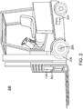
- Figure 2 illustrates a perspective view of the forklift 200 for facilitating automation of various tasks within a physical environment according to one or more embodiments of the present invention.
- the forklift 200 (i.e., a lift truck, a high/low, a stacker-truck, trailer loader, sideloader or a fork hoist) is a powered industrial truck having various load capacities and used to lift and transport various objects.
- the forklift 200 is configured to move one or more pallets (e.g., the pallets 112 of Figure 1 ) of units (e.g., the units 114 of Figure 1 ) along paths within the physical environment (e.g., the physical environment 100 of Figure 1 ).
- the paths may be pre-defined or dynamically computed as tasks are received.
- the forklift 200 may travel inside a storage bay that is multiple pallet positions deep to place or retrieve a pallet.
- the forklift 200 is guided into the storage bay and places the pallet on cantilevered arms or rails.
- the dimensions of the forklift 200 including overall width and mast width, must be accurate when determining an orientation associated with an object and/or a target destination.
- the forklift 200 typically includes two or more forks (i.e., skids or tines) for lifting and carrying units within the physical environment.
- the forklift 200 may include one or more metal poles (not pictured) in order to lift certain units (e.g., carpet rolls, metal coils and/or the like).
- the forklift 200 includes hydraulics-powered, telescopic forks that permit two or more pallets to be placed behind each other without an aisle between these pallets.
- the forklift 200 may further include various mechanical, hydraulic and/or electrically operated actuators according to one or more embodiments.
- the forklift 200 includes one or more hydraulic actuator (not labeled) that permit lateral and/or rotational movement of two or more forks.
- the forklift 200 includes a hydraulic actuator (not labeled) for moving the forks together and apart.
- the forklift 200 includes a mechanical or hydraulic component for squeezing a unit (e.g., barrels, kegs, paper rolls and/or the like) to be transported.
- the forklift 200 may be coupled with the mobile computer 104, which includes software modules for operating the forklift 200 in accordance with one or more tasks.
- the forklift 200 is also coupled with an array comprising various sensor devices (e.g., the sensor array 108 of Figure 1 ), which transmits sensor data (e.g., image data, video data, range map data and/or three-dimensional graph data) to the mobile computer 104 for extracting information associated with environmental features.
- sensor data e.g., image data, video data, range map data and/or three-dimensional graph data
- Exemplary embodiments of the forklift 200 typically includes a camera 202, a planar laser scanner 204 attached to each side and/or an encoder 206 attached to each wheel 208.
- the forklift 200 includes only the planar laser scanner 204 and the encoder 206.
- the forklift 200 may use any sensor array with a field of view that extends to a current direction of motion (e.g., travel forwards, backwards, fork motion up/down, reach out/in and/or the like).
- These encoders determine motion data related to vehicle movement.
- Externally mounted sensors may include laser scanners or cameras positioned where the rich data set available from such sensors would enhance automated operations.
- External sensors may include a limited set transponders and/or other active or passive means by which an automated vehicle could obtain an approximate position to see a localization function.
- a number of sensor devices e.g., laser scanners, laser range finders, encoders, pressure transducers and/or the like
- their position on the forklift 200 are vehicle dependent, and the position at which these sensors are mounted affects the processing of the measurement data. For example, by ensuring that all of the laser scanners are placed at a measurable position, the sensor array 108 may process the laser scan data and transpose it to a center point for the forklift 200. Furthermore, the sensor array 108 may combine multiple laser scans into a single virtual laser scan, which may be used by various software modules to control the forklift 200.
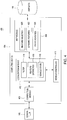
- Figure 3 is a structural block diagram of a system 300 for providing accurate localization for an industrial vehicle according to one or more embodiments.
- the system 300 includes the mobile computer 104, the central computer 106 and the sensor array 108 in which each component is coupled to each other through a network 302.
- the mobile computer 104 is a type of computing device (e.g., a laptop, a desktop, a Personal Desk Assistant (PDA) and the like) that comprises a central processing unit (CPU) 304, various support circuits 306 and a memory 308.
- the CPU 304 may comprise one or more commercially available microprocessors or microcontrollers that facilitate data processing and storage.
- Various support circuits 306 facilitate operation of the CPU 304 and may include clock circuits, buses, power supplies, input/output circuits and/or the like.
- the memory 308 includes a read only memory, random access memory, disk drive storage, optical storage, removable storage, and the like.
- the memory 308 includes various data, such as map data 310, a plurality of sub-area maps 312, feature information 314, pose measurement data 316, a vehicle heading 317, pose prediction data 318 and a path 319.
- the memory 308 includes various software packages, such as an environment based navigation module 320.
- the central computer 106 is a type of computing device (e.g., a laptop computer, a desktop computer, a Personal Desk Assistant (PDA) and the like) that comprises a central processing unit (CPU) 322, various support circuits 324 and a memory 326.
- the CPU 322 may comprise one or more commercially available microprocessors or microcontrollers that facilitate data processing and storage.
- Various support circuits 324 facilitate operation of the CPU 322 and may include clock circuits, buses, power supplies, input/output circuits and/or the like.
- the memory 326 includes a read only memory, random access memory, disk drive storage, optical storage, removable storage, and the like.
- the memory 326 includes various software packages, such as a mapping module 328, as well as various data, such as a task 330.
- the memory 326 stores a copy of global map data 310 (representing a global map) and/or the sub-area maps 312.
- the network 302 comprises a communication system that connects computing devices by wire, cable, fiber optic, and/or wireless links facilitated by various types of well-known network elements, such as hubs, switches, routers, and the like.
- the network 302 may employ various well-known protocols to communicate information amongst the network resources.
- the network 302 may be part of the Internet or intranet using various communications infrastructure such as Ethernet, WiFi, WiMax, General Packet Radio Service (GPRS), and the like.
- GPRS General Packet Radio Service
- the sensor array 108 is communicably coupled to the mobile computer 104, which is attached to an automated vehicle, such as a forklift (e.g., the forklift 200 of Figure 2 ).
- the sensor array 108 includes a plurality of devices 322 for monitoring a physical environment and capturing various data, which is stored by the mobile computer 104 as the sensor input messages 312.
- the sensor array 108 may include any combination of one or more laser scanners and/or one or more cameras.
- the sensor array includes a plurality of devices 332 mounted to the automated vehicle. For example, a laser scanner and a camera may be attached to a lift carriage at a position above the forks. Alternatively, the laser scanner and the camera may be located below the forks.
- the sensor array may also comprise devices 332 distributed throughout the physical environment at fixed positions.
- the global map data 310 includes static features of a physical environment.
- the global map data 310 includes dynamic features and static features of a physical environment, such a shared use area for human workers and automated industrial vehicles.
- the global map data 310 comprises feature information 340 and landmark data 342.
- the feature information includes dynamic and/or static features representing a physical environment proximate the vehicle, such as a shared use area for human workers and automated industrial vehicles.
- Static features represent objects that do not change within the environment, e.g., walls, storage racks, and the like.
- the local map data 310 may be organized to form a vector of known landmarks, static and dynamic features.
- feature information 340 include: feature geometry (line, corner, arc, etc.); a feature pose in global coordinate system; and a feature pose uncertainty. Typically, the pose uncertainty for static features is zero.
- dynamic features represent objects that change within the environment, e.g. temporary obstructions such as broken pallets, objects to be stored, and the like. These features are likely to be stationary for a sufficient amount of time for the system to use them as localization map features. The system does not contain a-priori information about the pose of these features and thus the pose of these dynamic features can only be inferred by superimposing the vehicle centric measurement from sensors onto the estimated pose of the vehicle with respect to the global coordinate system. Because of the noise in sensor data, as well as the uncertainty in the vehicle pose estimation, all dynamic features have a pose uncertainty associated with their pose.
- the physical environment is segmented into a plurality of sub-areas with corresponding map data stored in the plurality of sub-area maps 312.
- the feature information 314 defines features (e.g., curves, lines and/or the like) associated with various landmarks. These landmarks may be pre-defined and identified in a static map of the physical environment.
- the map module 328 may designate one or more objects (i.e., unloaded objects, such as a product item or pallet) as unique landmarks that correspond to specific sub-areas, such as a room in a warehouse
- the pose prediction data 318 includes an estimate of vehicle position and/or orientation of which the present disclosure may refer to as the vehicle pose prediction.
- the environment based navigation module 320 may produce such an estimate using a prior vehicle pose in addition to a vehicle motion model.
- the environment based navigation module 320 may also use a process filter to estimate uncertainty and/or noise for an upcoming vehicle pose prediction and update steps.
- the environment based navigation module 320 determines an estimate of a current vehicle position.
- the uncertainty in a vehicle pose creates an uncertainty in the position of observed features.
- the pose uncertainty in the feature information 312 is derived from a combination of vehicle position uncertainty and sensor noise.
- the environment based navigation module 320 includes processor-executable instructions for performing localization and mapping for an industrial vehicle.
- the environment based navigation module 320 reduces a number of known (landmark) features to compare with the feature information 314 by eliminating portions of the map data 310 from being processed during the localization.
- a number of static and/or dynamic landmarks being processed at any given time are limited to the number of landmarks in a particular sub-area map in which the industrial vehicle currently operates.
- the module 320 may request a sub-area map 312 from the central computer, or the central computer 106 may automatically send a new sub-area map as the vehicle approaches the edge of a prior sub-area map.
- the EBN module may contain a mobile map module 344 that extracts a sub-area map 312 from the locally stored map data 310.
- a map module 328/344 (global or mobile) constructs a new sub-area map 312 that corresponds with a portion of the physical environment required by the vehicle to navigate in the new location.
- the environment based navigation module 320 only uses known features associated with the new sub-area map 312.
- the environment based navigation module 320 updates the map data 310 with new dynamic features.
- FIG 4 is a functional block diagram of a system 400 for providing accurate localization for an industrial vehicle according to one or more embodiments.
- the system 400 includes the mobile computer 104, which couples to an industrial vehicle, such as a forklift, as well as the sensor array 108.
- Various software modules within the mobile computer 104 collectively form an environment based navigation module (e.g., the environment based navigation module 320 of Figure 3 ).
- the mobile computer 104 includes various software modules (i.e., components) for performing navigational functions, such as a localization module 402, a mapping module 404, a correction module 408, and a vehicle controller 410.
- the mobile computer 104 provides accurate localization for the industrial vehicle and updates map data 406 with information associated with environmental features.
- the localization module 402 also includes various components, such as a filter 414 and a feature extraction module 416 for determining a vehicle state 418.
- the map module 404 includes various data, such as dynamic features 422 and static features 424.
- the map module 404 also includes various components, such as a feature selection module 420.
- the sensor data is corrected in correction module 408 to correct for temporal and/or spatial distortion.
- the localization module 402 processes the corrected data and extracts features from the sensor data using feature extraction component 416. These features are matched with the features from map module 404, with the feature pose uncertainty and observation noise taken into account, and vehicle state 418 is then adjusted by the filter 414.
- the vehicle pose 418 which is modeled by the filter 414, refers to a current vehicle state and includes data (e.g., coordinates) that indicate vehicle position, orientation, velocity, acceleration and the like.
- the localization module 402 communicates data associated with the vehicle pose 418 to the mapping module 404 while also communicating such data to the vehicle controller 410. Based on the vehicle position and orientation, the vehicle controller 410 navigates the industrial vehicle to a destination.
- the localization module 402 also includes the feature extraction module 416 for extracting standard features from the corrected sensor data.
- the map module 404 compares the vehicle pose 418 with the static features 424 and dynamic features 422 to reduce a number of features to examine by eliminating features not currently visible from the features.
- the map module 404 partitions the map data 406 into a plurality of maps that correspond with specific sub-areas of the physical environment.
- the feature selection module 420 manages addition and modification of the dynamic features 422 to the map data 406.
- the feature selection module 420 can update the map data 406 to indicate areas recently occupied or cleared of certain features, such as known placed and picked items.
- the system 400 may employ several computing devices to perform environment based navigation. Any of the software modules within the computing device 104 may be deployed on different or multiple physical hardware components, such as other computing devices.
- the mapping module 404 may be executed on a server computer (e.g., the central computer 102 of Figure 1 ) over a network (e.g., the network 302 of Figure 4 ) to connect with multiple mobile computing devices for the purpose of sharing and updating the map data 406 with a current vehicle position and orientation.
- the correction module 408 processes sensor input messages from disparate data sources, such as the sensor array 108, having different sample/publish rates for the vehicle pose 418 as well as different (internal) system delays.
- the correction module 408 extracts observed pose measurements from the sensor data within these messages.
- the correction module 402 examines each message separately in order to preserve the consistency of each observation.
- FIG. 5 is an interaction diagram illustrating a localization and mapping process 500 for an industrial vehicle according to one or more embodiments.
- the localization and mapping process 500 includes processing and communicating various data between components or layers 502, such as sensor data correction 504, an interface 506, feature extraction 508, data association 510, EKF 512 and dynamic map 514.
- the localization and mapping process 500 supports industrial vehicle operation using primarily environmental features.
- the interface 506 facilitates control over the layers 502 and is added to an environment based navigation module.
- the feature extraction 508 examines data inputted by sensor devices and extracts observed features (e.g. lines and corners).
- the data association 510 compares the observed features with known feature information to identify matching features with existing static and/or dynamic map data.
- the EKF 512 is an extended Kalman Filter that, given measurements associated with the matching features and a previous vehicle pose, provides a most likely current vehicle pose.
- the dynamic map manager 514 maintains an up-to-date dynamic map of features used for localization that are not found in a-priori static map.
- Figure 6 is a schematic illustration of a map 600 for estimating a position for the industrial vehicle 102 according to one or more embodiments.
- Various software modules stored within a computer coupled to the industrial vehicle 102 execute the position estimation 600.
- the industrial vehicle 102 uses various sensor devices (e.g., the plurality of sensor devices 332 of Figure 3 ) to sense objects within a visibility range 602.
- the visibility range 602 may refer to a laser range that is formed by laser scanners.
- the industrial vehicle senses landmarks 604 whose features are used to form grid lines 606 for estimating the pose of an industrial vehicle according to some embodiments.
- the landmarks 604 combine to form an infrastructure unit 608.
- Physical environments such as a warehouse, include landmarks having related features, which can be extracted to facilitate localization and mapping.
- related features include the rack legs of high density racking where the set of legs form an infrastructure unit 608.
- Data associated with the infrastructure unit such as the virtual line, or gridline 606, that joins each and every leg in a racking bay may be used to assist localization.
- the virtual feature may be treated by the localization module (the localization module 402 of figure 4 ) equivalent to a virtual wall.
- the localization module the localization module 402 of figure 4
- a mobile computer e.g., the mobile computer 104 of Figure 1
- the industrial vehicle 102 identifies racking legs, which are stored as landmarks. Common features amongst the racking legs indicate that these landmarks are related. For example, each racking leg is similar or identical in size, shape and orientation to each other.
- the industrial vehicle 102 fits lines to these racking legs to provide gridlines 606 to correct a vehicle pose.
- walls are generally not within the range 602. Therefore, either these gridlines 606, or an aisle defined by both sets of parallel gridlines 606, can be used to adjust the vehicle position and heading.
- the gridline 606 and aisle is stored as a virtual feature in the map which is associated with the racking legs 604.
- Figure 7 is a functional block diagram illustrating a localization and mapping process 700 for navigating an industrial vehicle according to one or more embodiments.
- a time and distortion correction module 702 rearranges sensor input messages based on acquisition time.
- a geometry extract module 706 examines the corrected sensor data identifies candidate geometries from the sensor corrected sensor data.
- the known standard features 710 are selected using the current vehicle pose 712. The selection may be performed according to a specific sub-area of the physical environment, a sensor visibility constraint (e.g. the sensor range 602 of figure 6 ) or other selection criteria that are well known in the art.
- the geometries from the sensor data are associated with the features 708 as the resulting identified features list presented to the filter 714. Accordingly, such a reduction in a number of features to process enhances feature association data processing and filter data processing by limiting the number of features to be processed.
- the filter 714 uses the feature list and the corrected odometry sensor data, the filter 714 updates a pose prediction/estimation as well as map data.
- the filter 714 provides real time positioning information (localization) for an automated industrial vehicle or manually driven vehicle.
- the filter 714 also helps provide data indicating uncertainty associated with the vehicle pose measurements.
- the filter 714 continues to provide accurate localization by updating the vehicle pose along with determining indicia of uncertainty.
- the industrial vehicle may operate within a defined degree of uncertainty before an error triggers the alarm 718.
- the module 704 receives readings (i.e., observations) taken from each sensor device. These readings may be provided by a laser and/or camera or any other type of sensor device for extracting environment features.
- the time and distortion correction step 702 also corrects for any distortion that may be due to finite measurement time and the speed of travel of the industrial vehicle. This distortion occurs as the industrial vehicle and sensors are moving (e.g., during a scan), which associates a temporal characteristic with the data.
- the module 706 extracts various environment features from the sensor data, such as a line, corner, arc, or marker, which are provided in a standard geometry format for data association 708. Pose measurements from the sensor devices 704 provide a relative change in position, velocity, or acceleration.
- the known feature list 710 includes a map of a physical environment.
- the data association 708 compares a subset of the known feature list 710 provided by feature selection 712 with the extracted standard geometries in order to estimate vehicle position.
- the vehicle pose include x-y coordinates associated with the vehicle position as well as a vehicle heading.
- the odometry data provides gives a linear velocity and a rotational velocity.
- the linear velocity refers to the velocity of the wheel upon which an encoder or velocity measurement device is installed.
- the rotational velocity indicates how much the heading of the vehicle has changed with respect to the global coordinate system and the vehicle.
- the filter 714 corrects the vehicle pose by eliminating process noise (i.e., odometry noise) by modeling wheel slip (proportional to linear velocity) and angular slip (proportional to angular velocity).
- Figure 8 is a flow diagram of a method for partitioning map data into sub-area maps according to one or more embodiments.
- an environment based navigation module e.g., the environment based navigation module 320 of Figure 3
- a mapping module e.g., the mapping module 328 of Figure 3
- the environment based navigation module is stored within a mobile computer (e.g., the mobile computer 104 of Figure 1 ) that is operably coupled to an industrial vehicle (e.g., the industrial vehicle 102 of Figure 1 ).
- the map module is stored within a central computer or mobile computer (e.g., the central computer 106 or mobile computer 104 of Figure 1 ) that communicates with the industrial vehicle as well as one or more second industrial vehicles.
- a central computer or mobile computer e.g., the central computer 106 or mobile computer 104 of Figure 1
- the central computer instructs the mobile computer to navigate the industrial vehicle along a particular path (e.g., the path 319 of Figure 3 ).
- the method 800 starts at step 802 and proceeds to step 804.
- the method 800 processes map data (e.g., the map data 310 of Figure 3 ).
- the environment based navigation module examines the map data in order to localize the industrial vehicle. Before following the path, the environment based navigation must determine an accurate vehicle pose.
- the map module may optionally communicate map data (e.g., the map data 310 of Figure 3 ) to the mobile computer.
- map data may be a global map of an entire physical environment (e.g., the physical environment 100 of Figure 1 ) or a sub area map.
- the method 800 segments the map data into a plurality of sub-area maps.
- Each sub-area map may be associated with a certain portion of the physical environment, such as a specific room of a warehouse.
- the method 800 uses feature information associated with the physical environment.
- the method 800 defines a sub-area map based on vehicle pose and other available information such as the planned path for the vehicle.
- These sub-area maps contains a subset of landmarks expected to be seen by the vehicle given its pose and, for example, planned path. These landmarks may include static, dynamic, and/or virtual features.
- the method 800 determines a current vehicle location.
- the method 800 accesses the map data and extracts a vehicle pose (e.g., the vehicle pose 318) that includes the current vehicle location.
- the method 800 generates a sub-area map that corresponds with the current vehicle location.
- the sub-area map includes feature information for a sub-area of the physical environment that would be likely to be observed by the industrial vehicle.
- the method 800 navigates the industrial vehicle using the identified sub-area map.
- the environment based navigation module directly controls vehicle operations and navigates the industrial vehicle along the path according to some embodiments.
- the method 800 identifies another sub-area map that corresponds with a new vehicle location.
- the environment based navigation module requests the other sub-area map from the map module and the map module creates the sub-area map upon request.
- the map module selects the other sub-area map from the plurality of sub-area maps.
- the sub-area maps are generated (or selected) as a sequence.
- Each map is provided by the map module prior to the vehicle reaching the edge of the current map.
- the maps generally overlap in coverage such that a gap in map information is not created as the vehicle moves from one sub-area map coverage to the next.
- step 814 the method 800 ends.
- FIG 9 is a flow diagram of a method 900 for facilitating map data processing according to one or more embodiments.
- an environment based navigation module e.g., the environment based navigation module 320 of Figure 3
- a mapping module e.g., the map module 328/344 of Figure 3
- the environment based navigation module is stored within a mobile computer (e.g., the mobile computer 104 of Figure 1 ) that is operably coupled to an industrial vehicle (e.g., the industrial vehicle 102 of Figure 1 ).
- the map module is stored within a central computer or the mobile computer that communicates with the industrial vehicle as well as one or more second industrial vehicles.
- the central computer instructs the mobile computer to navigate the industrial vehicle along a particular path (e.g., the path 319 of Figure 3 ).
- the method 900 starts at step 902 and proceeds to step 904.
- the method 900 processes map data by selecting a subset of features from the map that are likely to be observed by the industrial vehicle. Processing the map data will reduce the number and landmarks and consequently features to be processed by the industrial vehicle to those in the proximate area of the industrial vehicle.
- the method 900 identifies landmarks that have common features to which virtual landmarks may be mapped. These landmarks may include static (e.g. racking legs), dynamic (e.g. pallets placed during system operation).
- the identified landmarks are mapped to the virtual landmarks stored in the map (e.g. the aisle formed by rows of racking system).
- all landmarks are expanded into features that may be detected by the sensor array 108 associated with an industrial vehicle. These features may be geometric representation of the physical landmarks, such as lines and arcs.
- the method 900 updates the map data with the selected feature information.
- the method 900 fits the feature information with known feature information for the infrastructure unit. For example, the method 900 compares the feature information with known dimension data for the racking system.
- the method 900 determines a vehicle pose prediction according to odometry sensor data (e.g., pose prediction data 318 of Figure 3 ). In some embodiments, the method 900 examines a previous vehicle pose and predicts a new vehicle pose after a time interval.
- the method 900 processes pose measurements.
- the method 900 corrects the vehicle pose prediction. After sensing pose measurement data (e.g., the pose measurement data 316 of Figure 3 ) related to one or more landmarks, the method 900 updates the vehicle pose prediction to produce an accurate vehicle pose.
- pose measurement data e.g., the pose measurement data 316 of Figure 3
- the method 900 determines whether the change to the map requires the vehicle to recalculate a path in order to complete the task (e.g., the path 319 of Figure 3 ). If the method 900 decides to recalculate the path, the method 900 proceeds to step 922. If, on the other hand, the method 900 decides not to update the path, the method 900 proceeds to step 924. At step 922, the method 900 recalculates the path. At step 924, the method 900 determines whether to continue performing localization and mapping for executing the task. If the method 900 decides to continue performing the localization and mapping, the method 900 returns to step 912. If, on the other hand, the method 900 decides not to continue, the method 900 proceeds to step 926. At step 926, the method 900 ends.
Claims (12)
- Verfahren zum Aufteilen von Kartendaten für Industriefahrzeugnavigation in einer physischen Umgebung, wobei:die physische Umgebung statische Merkmale, die Objekte darstellen, die sich innerhalb der physischen Umgebung nicht ändern, und dynamische Merkmale, die Objekte darstellen, die sich innerhalb der physischen Umgebung ändern, umfasst,ein mobiler Rechner (104) an dem Industriefahrzeug befestigt ist und eine Sensoranordnung (108) kommunizierbar mit dem mobilen Rechner (104) verbunden ist,der mobile Rechner (104) eine Zentraleinheit (304) und einen Speicher (308) umfasst, wobei der Speicher ein umgebungsbasiertes Navigationsmodul (320) umfasst, wobei der mobile Rechner (104) ein Kartenmodul (404) einschließt, wobei das Kartenmodul ein Merkmalsauswahlmodul (420) einschließt, wobei Kartendaten statische Merkmale (424) innerhalb der physischen Umgebung darstellen und der Speicher (308) mehrere Untergebietskarten umfasst,die Sensoranordnung (108) mehrere Geräte (332) umfasst, die an dem Industriefahrzeug (102, 200) angebracht sind, zum Überwachen der physischen Umgebung und Erfassen von Sensordaten, welche die physische Umgebung darstellen, unddas Verfahren Folgendes umfasst:Segmentieren der physischen Umgebung, wie sie durch die Kartendaten dargestellt wird, in mehrere Untergebiete mit entsprechenden Kartendaten, die in den mehreren Untergebietskarten (312) gespeichert sind,Benutzen des umgebungsbasierten Navigationsmoduls (320) und von Umgebungsmerkmalen, die aus den Sensordaten extrahiert werden, um einen Standort des Industriefahrzeugs im Verhältnis zu einem bestimmten Untergebiet festzustellen,Benutzen des umgebungsbasierten Navigationsmoduls (320), um jeweilige Stellungsunbestimmtheiten, die mit den dynamischen Merkmalen verknüpft sind, auf der Grundlage von Daten abzuleiten, die Rauschen in den Sensordaten und Unbestimmtheit bei dem festgestellten Standort des Industriefahrzeugs umfassen,Auswählen einer Untergebietskarte (312) zur Verwendung durch das umgebungsbasierte Navigationsmodul auf der Grundlage des festgestellten Standorts des Industriefahrzeugs,Benutzen des Merkmalsauswahlmoduls (420), um das Hinzufügen dynamischer Merkmale zu der Untergebietskarte auf der Grundlage der jeweiligen Stellungsunbestimmtheiten, die mit den dynamischen Merkmalen verknüpft sind zu handhaben, und Aktualisieren der ausgewählten Untergebietskarte durch das umgebungsbasierte Navigationsmodul (320), um dynamische Merkmale innerhalb des bestimmten Untergebiets einzuschließen,Benutzen des umgebungsbasierten Navigationsmoduls (320), um eine Abschätzung des gegenwärtigen Standorts des Industriefahrzeugs und ihre Unbestimmtheit auf der Grundlage der aktualisierten Untergebietskarte zu bestimmen, undNavigieren des Industriefahrzeugs unter Verwendung der aktualisierten Untergebietskarte und des gegenwärtigen Standorts des Industriefahrzeugs.
- Verfahren nach Anspruch 1, wobei die ausgewählte Untergebietskarte durch Verwendung des Merkmalsauswahlmoduls aktualisiert wird, um Merkmale zu beseitigen, die gegenwärtig nicht innerhalb der Sensordaten sichtbar sind, auf der Grundlage eines Vergleichs der Fahrzeugstellung mit statischen und dynamischen Merkmalen.
- Verfahren nach Anspruch 1, wobei die Untergebietskarte (312) Merkmalsinformationen für ein Untergebiet der physischen Umgebung, die wahrscheinlich durch das Industriefahrzeug wahrzunehmen wären, einschließt.
- Verfahren nach Anspruch 1, wobei das Verfahren ferner das Auslösen eines Alarms umfasst, wenn das Industriefahrzeug außerhalb eines definierten Grades von Unbestimmtheit arbeitet, die mit der Fahrzeugstellung verbunden ist.
- Verfahren nach Anspruch 1, wobei das Verfahren ferner Folgendes umfasst:Schlussfolgern einer Stellung der dynamischen Merkmale durch Überlagern von fahrzeugzentrischen Messungen von den Sensoranordnungsvorrichtungen auf eine abgeschätzte Stellung des Industriefahrzeugs in Bezug auf ein globales Koordinatensystem undModifizieren der dynamischen Merkmale der ausgewählten Untergebietskarte.
- Verfahren nach Anspruch 1, wobei sich die Stellung des Industriefahrzeugs auf einen gegenwärtigen Fahrzeugzustand bezieht und Positionsdaten, Ausrichtungsdaten und Geschwindigkeitsdaten umfasst.
- Verfahren nach Anspruch 1, wobei die Sensoranordnung (108) eine oder mehrere Kameras umfasst.
- Verfahren nach Anspruch 1, wobei das umgebungsbasierte Navigationsmodul (320) eine neue Untergebietskarte durch Anfordern der Untergebietskarte (312) von dem mobilen Rechner (104) auswählt.
- Verfahren nach Anspruch 1, wobei die Untergebietskarte (312) ausgewählt wird, wenn sich das Industriefahrzeug dem Rand einer vorherigen Untergebietskarte annähert.
- Verfahren nach Anspruch 1, wobei der mobile Rechner (104) in Kommunikation mit einem zweiten Industriefahrzeug steht und die ausgewählte Untergebietskarte (312) aktualisiert wird, um Merkmalsinformationen einzuschließen, die durch das zweite Industriefahrzeug mitgeteilt werden.
- Verfahren nach Anspruch 1, wobei:
die physische Umgebung einen dynamischen Bereich gemeinsamer Nutzung umfasst, in dem zu erwarten ist, dass Paletten auf einem Boden der physischen Umgebung platziert sind. - Verfahren nach Anspruch 11, wobei das Merkmalsauswahlmodul (420) ferner dazu benutzt wird, Kartendaten zu aktualisieren, um Bereiche anzugeben, die kürzlich durch platzierte oder aufgenommene Gegenstände eingenommen oder von denselben geräumt wurden.
Applications Claiming Priority (2)
| Application Number | Priority Date | Filing Date | Title |
|---|---|---|---|
| US13/159,501 US8589012B2 (en) | 2011-06-14 | 2011-06-14 | Method and apparatus for facilitating map data processing for industrial vehicle navigation |
| PCT/NZ2012/000091 WO2012173496A1 (en) | 2011-06-14 | 2012-06-08 | Method and apparatus for facilitating map data processing for industrial vehicle navigation |
Publications (2)
| Publication Number | Publication Date |
|---|---|
| EP2721373A1 EP2721373A1 (de) | 2014-04-23 |
| EP2721373B1 true EP2721373B1 (de) | 2018-08-08 |
Family
ID=46598914
Family Applications (1)
| Application Number | Title | Priority Date | Filing Date |
|---|---|---|---|
| EP12741123.9A Active EP2721373B1 (de) | 2011-06-14 | 2012-06-08 | Verfahren zur kartendatenverarbeitung für industriefahrzeugnavigation |
Country Status (9)
| Country | Link |
|---|---|
| US (1) | US8589012B2 (de) |
| EP (1) | EP2721373B1 (de) |
| KR (1) | KR101437952B1 (de) |
| CN (1) | CN103635779B (de) |
| AU (1) | AU2012269799B2 (de) |
| BR (1) | BR112013032070A2 (de) |
| CA (1) | CA2837776C (de) |
| RU (1) | RU2542932C1 (de) |
| WO (1) | WO2012173496A1 (de) |
Families Citing this family (39)
| Publication number | Priority date | Publication date | Assignee | Title |
|---|---|---|---|---|
| EP2562309B1 (de) * | 2011-08-22 | 2014-04-02 | Joseph Vögele AG | Straßenfertiger mit Messvorrichtung |
| WO2013033193A1 (en) * | 2011-08-29 | 2013-03-07 | Crown Equipment Corporation | Forklift navigation system |
| BR112014004817A2 (pt) | 2011-08-29 | 2017-05-30 | Crow Equipment Corp | sistema para prover uma interface de controle de navegação veicular, e, veículo |
| EP4167042A1 (de) | 2011-08-29 | 2023-04-19 | Crown Equipment Corporation | Multimodale fahrzeugnavigationssteuerung |
| US9969081B2 (en) * | 2012-07-27 | 2018-05-15 | Alberto Daniel Lacaze | Method and system for the directed control of robotic assets |
| CN103278153B (zh) * | 2013-04-27 | 2016-01-13 | 中南大学 | 一种基于空间二维映射的汽车起重机三维路径规划方法 |
| US9354070B2 (en) | 2013-10-31 | 2016-05-31 | Crown Equipment Corporation | Systems, methods, and industrial vehicles for determining the visibility of features |
| CN104376286A (zh) * | 2014-11-24 | 2015-02-25 | 苏州立瓷电子技术有限公司 | 一种基于rfid的叉车定位监控系统 |
| US9358975B1 (en) | 2015-04-10 | 2016-06-07 | Google Inc. | Virtual moving safety limits for vehicles transporting objects |
| EP3304002B1 (de) | 2015-05-26 | 2019-02-06 | Crown Equipment Corporation | Systeme und verfahren zur odometriekalibrierung eines materialhandhabungsfahrzeugs |
| CA2986698C (en) | 2015-05-26 | 2023-08-01 | Crown Equipment Corporation | Systems and methods for image capture device calibration for a materials handling vehicle |
| EP3130891B1 (de) * | 2015-08-11 | 2018-01-03 | Continental Automotive GmbH | Verfahren zur aktualisierung einer präzisionsstrassendatenbank auf einem server |
| CN105446334A (zh) * | 2015-11-13 | 2016-03-30 | 上海诺力智能科技有限公司 | 一种引导车导航系统及一种引导车导航方法 |
| CN109313829B (zh) * | 2016-06-24 | 2021-08-20 | 克朗设备公司 | 间接电子徽章跟踪 |
| KR102299378B1 (ko) * | 2016-08-24 | 2021-09-07 | 구글 엘엘씨 | 변화 검출 기반의 맵 인터페이스 업데이트 시스템 |
| EP4060288A3 (de) * | 2016-08-31 | 2023-02-01 | Topcon Positioning Systems, Inc. | Vorrichtung und verfahren zur fahrzeugpositionierung |
| DE102017204357A1 (de) * | 2017-03-16 | 2018-09-20 | Robert Bosch Gmbh | Verfahren und Vorrichtung zum Aktualisieren einer digitalen Karte zur Fahrzeugnavigation |
| US10429188B2 (en) * | 2017-03-30 | 2019-10-01 | Crown Equipment Corporation | Warehouse mapping tools |
| WO2018218146A1 (en) * | 2017-05-26 | 2018-11-29 | Google Llc | Data layers for a vehicle map service |
| KR102064222B1 (ko) * | 2017-09-22 | 2020-03-02 | 엘지전자 주식회사 | 차량의 운행 시스템을 제어하는 방법 |
| US11117743B2 (en) | 2017-09-28 | 2021-09-14 | Symbotic Llc | Storage and retrieval system |
| DE102018104780A1 (de) * | 2018-03-02 | 2019-09-05 | Sick Ag | Verfahren zur Bestimmung einer elektronischen nützbaren Repräsentation einer Umgebung, Vorrichtung hierfür, Datenträger |
| CN114440898A (zh) * | 2018-04-03 | 2022-05-06 | 御眼视觉技术有限公司 | 用于车辆导航的系统和方法 |
| US20190339082A1 (en) * | 2018-05-02 | 2019-11-07 | Blackberry Limited | Method and system for hybrid collective perception and map crowdsourcing |
| CN108762277A (zh) * | 2018-06-11 | 2018-11-06 | 蚁群(上海)智能装备有限公司 | 一种分布式agv调度方法及调度系统 |
| CN109141446B (zh) * | 2018-07-04 | 2021-11-12 | 阿波罗智能技术(北京)有限公司 | 用于获得地图的方法、装置、设备和计算机可读存储介质 |
| AU2019305588A1 (en) | 2018-07-17 | 2021-02-25 | Crown Equipment Corporation | Systems and methods for vehicle position calibration using rack leg identification |
| CN110836668A (zh) * | 2018-08-16 | 2020-02-25 | 科沃斯商用机器人有限公司 | 定位导航方法、装置、机器人及存储介质 |
| DE102018215560A1 (de) * | 2018-08-28 | 2020-03-05 | Robert Bosch Gmbh | Verfahren zum Koordinieren und Überwachen von Objekten |
| MX2021009139A (es) * | 2019-02-06 | 2021-12-10 | Crown Equip Corp | Sistemas y metodos para la proteccion del final de pasillo y calibracion de posicion de vehiculo mediante la identificacion de pata de rejilla. |
| WO2020172039A1 (en) * | 2019-02-19 | 2020-08-27 | Crown Equipment Corporation | Systems and methods for calibration of a pose of a sensor relative to a materials handling vehicle |
| CN110146110B (zh) * | 2019-05-20 | 2022-11-15 | 哈尔滨工程大学 | 一种室内环境机器人线特征icnn数据关联的误匹配判定方法 |
| DE102019128253A1 (de) * | 2019-10-18 | 2021-04-22 | StreetScooter GmbH | Verfahren zum Navigieren eines Flurförderzeugs |
| US11919761B2 (en) * | 2020-03-18 | 2024-03-05 | Crown Equipment Corporation | Based on detected start of picking operation, resetting stored data related to monitored drive parameter |
| CN112180940A (zh) * | 2020-10-16 | 2021-01-05 | 三一机器人科技有限公司 | 用于有反定位的建图方法及装置、车辆运行方法及装置 |
| CN113539043A (zh) * | 2021-07-14 | 2021-10-22 | 王康静 | 一种电子信息工程物联网综合实验设备、系统及其实验方法 |
| KR102571837B1 (ko) * | 2021-11-25 | 2023-08-30 | 웨이즈원 주식회사 | V2x 메시지 처리 장치 및 방법 |
| US20230418297A1 (en) * | 2022-06-23 | 2023-12-28 | Boston Dynamics, Inc. | Ground clutter avoidance for a mobile robot |
| US11885625B1 (en) | 2022-10-03 | 2024-01-30 | Googe Llc | Data fusion system |
Family Cites Families (76)
| Publication number | Priority date | Publication date | Assignee | Title |
|---|---|---|---|---|
| JPS6067818A (ja) | 1983-09-22 | 1985-04-18 | Hitachi Ltd | 車載用ナビゲ−タ |
| US4855915A (en) | 1987-03-13 | 1989-08-08 | Dallaire Rodney J | Autoguided vehicle using reflective materials |
| US4858132A (en) | 1987-09-11 | 1989-08-15 | Ndc Technologies, Inc. | Optical navigation system for an automatic guided vehicle, and method |
| US5011358A (en) | 1988-10-25 | 1991-04-30 | Andersen Eric T | Height indicator for a fork lift truck |
| US5179329A (en) | 1989-04-25 | 1993-01-12 | Shinko Electric Co., Ltd. | Travel control method, travel control device, and mobile robot for mobile robot systems |
| US5051906A (en) | 1989-06-07 | 1991-09-24 | Transitions Research Corporation | Mobile robot navigation employing retroreflective ceiling features |
| US5956250A (en) | 1990-02-05 | 1999-09-21 | Caterpillar Inc. | Apparatus and method for autonomous vehicle navigation using absolute data |
| US5170352A (en) | 1990-05-07 | 1992-12-08 | Fmc Corporation | Multi-purpose autonomous vehicle with path plotting |
| US5202832A (en) * | 1991-01-29 | 1993-04-13 | R. R. Donnelley & Sons Co. | Material handling automation system using portable transfer module |
| US5491670A (en) | 1993-01-21 | 1996-02-13 | Weber; T. Jerome | System and method for sonic positioning |
| US5539638A (en) | 1993-08-05 | 1996-07-23 | Pavilion Technologies, Inc. | Virtual emissions monitor for automobile |
| US5471393A (en) | 1994-01-26 | 1995-11-28 | Bolger; Joe | Driver's associate: a system for vehicle navigation and driving assistance |
| US5961571A (en) | 1994-12-27 | 1999-10-05 | Siemens Corporated Research, Inc | Method and apparatus for automatically tracking the location of vehicles |
| US5916285A (en) | 1995-10-18 | 1999-06-29 | Jervis B. Webb Company | Method and apparatus for sensing forward, reverse and lateral motion of a driverless vehicle |
| SE9601440D0 (sv) | 1996-04-15 | 1996-04-15 | Apogeum Ab | Förfarande för positionsbestämning av ett flertal fasta objekt |
| US6092010A (en) | 1997-09-03 | 2000-07-18 | Jervis B. Webb Company | Method and system for describing, generating and checking non-wire guidepaths for automatic guided vehicles |
| SE511504C2 (sv) | 1997-10-17 | 1999-10-11 | Apogeum Ab | Sätt och anordning för associering av anonyma reflektorer till detekterade vinkellägen |
| DE19757333C1 (de) | 1997-12-22 | 1999-09-16 | Litef Gmbh | Selbsttätige, schnelle Kalibrierung einer bordautonomen Messung eines Geschwindigkeitsvektors |
| JPH11296229A (ja) | 1998-02-13 | 1999-10-29 | Komatsu Ltd | 車両の誘導装置 |
| JP3316841B2 (ja) | 1998-08-06 | 2002-08-19 | 村田機械株式会社 | 無人搬送車システム |
| JP3316842B2 (ja) | 1998-08-06 | 2002-08-19 | 村田機械株式会社 | 無人搬送車システムと無人搬送車の誘導方法 |
| US7123166B1 (en) | 2000-11-17 | 2006-10-17 | Haynes Michael N | Method for managing a parking lot |
| JP2002048579A (ja) | 2000-04-28 | 2002-02-15 | Matsushita Electric Ind Co Ltd | 通信型ナビゲーションシステム |
| US6917839B2 (en) * | 2000-06-09 | 2005-07-12 | Intellectual Assets Llc | Surveillance system and method having an operating mode partitioned fault classification model |
| JP2002108446A (ja) | 2000-09-29 | 2002-04-10 | Nippon Seiki Co Ltd | 移動体の誘導方法 |
| US6428439B1 (en) | 2000-10-04 | 2002-08-06 | Gkn Automotive, Inc. | Integrated viscous transmission in a differential |
| US6952488B2 (en) | 2001-08-27 | 2005-10-04 | Carnegie Mellon University | System and method for object localization |
| JP3968501B2 (ja) | 2001-11-30 | 2007-08-29 | ソニー株式会社 | ロボットの自己位置同定システム及び自己位置同定方法 |
| US7844364B2 (en) | 2002-04-16 | 2010-11-30 | Irobot Corporation | Systems and methods for dispersing and clustering a plurality of robotic devices |
| AU2003223091A1 (en) * | 2002-04-30 | 2003-11-17 | Telmap Ltd. | Dynamic navigation system |
| DE10220936A1 (de) | 2002-05-10 | 2003-12-04 | Siemens Ag | Vorrichtung zur Lokalisierung mit festen und/oder veränderlichen Landmarken |
| US20050149256A1 (en) * | 2002-05-10 | 2005-07-07 | Siemens Aktiengesellschaft | Device for determining the position by means of fixed and/or variable landmarks |
| GB2389947B (en) | 2002-07-25 | 2004-06-02 | Golden River Traffic Ltd | Automatic validation of sensing devices |
| DE10234730A1 (de) * | 2002-07-30 | 2004-02-19 | Josef Schreiner | Verfahren zur Positionsbestimmung eines Transportfahrzeuges |
| KR100495635B1 (ko) * | 2002-09-02 | 2005-06-16 | 엘지전자 주식회사 | 네비게이션 시스템의 위치오차 보정방법 |
| KR100498987B1 (ko) * | 2002-10-11 | 2005-07-01 | 엘지전자 주식회사 | Gps 위치 데이터 수신 불량 지역에서의 이동체 위치예측 방법 |
| US7177737B2 (en) | 2002-12-17 | 2007-02-13 | Evolution Robotics, Inc. | Systems and methods for correction of drift via global localization with a visual landmark |
| KR100506533B1 (ko) | 2003-01-11 | 2005-08-05 | 삼성전자주식회사 | 이동로봇 및 그에 따른 자율주행 시스템 및 방법 |
| US7319877B2 (en) * | 2003-07-22 | 2008-01-15 | Microsoft Corporation | Methods for determining the approximate location of a device from ambient signals |
| JP4409904B2 (ja) | 2003-10-08 | 2010-02-03 | 株式会社日立製作所 | 経路情報提供システムおよび経路情報提供方法 |
| KR100982058B1 (ko) * | 2003-10-20 | 2010-09-13 | 엘지전자 주식회사 | 이동체의 지도 데이터 관리 방법 |
| US7689321B2 (en) | 2004-02-13 | 2010-03-30 | Evolution Robotics, Inc. | Robust sensor fusion for mapping and localization in a simultaneous localization and mapping (SLAM) system |
| JP5056009B2 (ja) | 2004-03-03 | 2012-10-24 | 日本電気株式会社 | 測位システム、測位方法、及びそのプログラム |
| KR100571837B1 (ko) | 2004-03-05 | 2006-04-17 | 삼성전자주식회사 | 자율주행기기의 주행제어방법 및 장치 |
| US7720554B2 (en) | 2004-03-29 | 2010-05-18 | Evolution Robotics, Inc. | Methods and apparatus for position estimation using reflected light sources |
| US7148458B2 (en) | 2004-03-29 | 2006-12-12 | Evolution Robotics, Inc. | Circuit for estimating position and orientation of a mobile object |
| KR100703692B1 (ko) | 2004-11-03 | 2007-04-05 | 삼성전자주식회사 | 공간상에 존재하는 오브젝트들을 구별하기 위한 시스템,장치 및 방법 |
| US20100222925A1 (en) | 2004-12-03 | 2010-09-02 | Takashi Anezaki | Robot control apparatus |
| WO2006065563A2 (en) | 2004-12-14 | 2006-06-22 | Sky-Trax Incorporated | Method and apparatus for determining position and rotational orientation of an object |
| US8497761B2 (en) | 2005-01-13 | 2013-07-30 | Rite-Hite Holding Corporation | System and method for remotely controlling docking station components |
| US8930023B2 (en) | 2009-11-06 | 2015-01-06 | Irobot Corporation | Localization by learning of wave-signal distributions |
| KR101323597B1 (ko) * | 2005-09-02 | 2013-11-01 | 니토 로보틱스 인코퍼레이티드 | 다기능 로봇 장치 |
| GB0520576D0 (en) | 2005-10-10 | 2005-11-16 | Applied Generics Ltd | Using traffic monitoring information to provide better driver route planning |
| DE112006003044T5 (de) | 2005-10-21 | 2008-10-23 | Deere & Company, Moline | Vielseitiges Robotersteuermodul |
| US8381982B2 (en) | 2005-12-03 | 2013-02-26 | Sky-Trax, Inc. | Method and apparatus for managing and controlling manned and automated utility vehicles |
| US7634336B2 (en) | 2005-12-08 | 2009-12-15 | Electronics And Telecommunications Research Institute | Localization system and method of mobile robot based on camera and landmarks |
| US7616642B2 (en) | 2006-01-04 | 2009-11-10 | Sap Ag | Priority assignment and transmission of sensor data |
| US8050863B2 (en) | 2006-03-16 | 2011-11-01 | Gray & Company, Inc. | Navigation and control system for autonomous vehicles |
| US7646336B2 (en) | 2006-03-24 | 2010-01-12 | Containertrac, Inc. | Automated asset positioning for location and inventory tracking using multiple positioning techniques |
| US8996172B2 (en) * | 2006-09-01 | 2015-03-31 | Neato Robotics, Inc. | Distance sensor system and method |
| JP4975503B2 (ja) | 2007-04-06 | 2012-07-11 | 本田技研工業株式会社 | 脚式移動ロボット |
| JP4328813B2 (ja) | 2007-04-06 | 2009-09-09 | 本田技研工業株式会社 | 移動装置、ならびにその制御方法および制御プログラム |
| DE102007021693A1 (de) | 2007-05-09 | 2008-11-13 | Götting jun., Hans-Heinrich, Dipl.-Ing. (FH) | Hilfssystem zur Lagebestimmung eines Fahrzeugs |
| JP5047709B2 (ja) * | 2007-07-04 | 2012-10-10 | 株式会社日立製作所 | 移動装置、システム、移動方法及び移動プログラム |
| WO2009007983A2 (en) | 2007-07-12 | 2009-01-15 | Carmel - Haifa University Economic Corp Ltd. | Localization method for mobile robots based on landmarks |
| US20090140887A1 (en) | 2007-11-29 | 2009-06-04 | Breed David S | Mapping Techniques Using Probe Vehicles |
| US20090216438A1 (en) | 2008-02-21 | 2009-08-27 | Microsoft Corporation | Facility map framework |
| US8126642B2 (en) | 2008-10-24 | 2012-02-28 | Gray & Company, Inc. | Control and systems for autonomously driven vehicles |
| JP4655139B2 (ja) | 2008-11-19 | 2011-03-23 | トヨタ自動車株式会社 | 移動体位置測位装置 |
| KR101214143B1 (ko) | 2008-12-22 | 2012-12-20 | 한국전자통신연구원 | 이동체의 위치 및 방향 인식 장치 및 그 방법 |
| CN102782600B (zh) | 2009-11-27 | 2015-06-24 | 丰田自动车株式会社 | 自动移动体及其控制方法 |
| US8340438B2 (en) | 2009-12-17 | 2012-12-25 | Deere & Company | Automated tagging for landmark identification |
| US20110153338A1 (en) | 2009-12-17 | 2011-06-23 | Noel Wayne Anderson | System and method for deploying portable landmarks |
| US20120101784A1 (en) | 2010-10-25 | 2012-04-26 | Trimble Navigation Limited | Wide-area agricultural monitoring and prediction |
| US20120191272A1 (en) | 2011-01-24 | 2012-07-26 | Sky-Trax, Inc. | Inferential load tracking |
| US8594923B2 (en) * | 2011-06-14 | 2013-11-26 | Crown Equipment Limited | Method and apparatus for sharing map data associated with automated industrial vehicles |
-
2011
- 2011-06-14 US US13/159,501 patent/US8589012B2/en active Active
-
2012
- 2012-06-08 CN CN201280029042.7A patent/CN103635779B/zh active Active
- 2012-06-08 AU AU2012269799A patent/AU2012269799B2/en active Active
- 2012-06-08 BR BR112013032070A patent/BR112013032070A2/pt not_active Application Discontinuation
- 2012-06-08 KR KR1020147000894A patent/KR101437952B1/ko active IP Right Grant
- 2012-06-08 RU RU2013154309/08A patent/RU2542932C1/ru not_active IP Right Cessation
- 2012-06-08 CA CA2837776A patent/CA2837776C/en active Active
- 2012-06-08 EP EP12741123.9A patent/EP2721373B1/de active Active
- 2012-06-08 WO PCT/NZ2012/000091 patent/WO2012173496A1/en unknown
Non-Patent Citations (1)
| Title |
|---|
| None * |
Also Published As
| Publication number | Publication date |
|---|---|
| US8589012B2 (en) | 2013-11-19 |
| CN103635779B (zh) | 2016-08-17 |
| RU2542932C1 (ru) | 2015-02-27 |
| AU2012269799A1 (en) | 2013-05-02 |
| WO2012173496A8 (en) | 2013-02-21 |
| CA2837776A1 (en) | 2012-12-20 |
| EP2721373A1 (de) | 2014-04-23 |
| US20120323432A1 (en) | 2012-12-20 |
| CN103635779A (zh) | 2014-03-12 |
| AU2012269799B2 (en) | 2014-05-15 |
| CA2837776C (en) | 2014-12-09 |
| KR101437952B1 (ko) | 2014-09-05 |
| BR112013032070A2 (pt) | 2016-12-13 |
| KR20140038523A (ko) | 2014-03-28 |
| WO2012173496A1 (en) | 2012-12-20 |
Similar Documents
| Publication | Publication Date | Title |
|---|---|---|
| EP2721373B1 (de) | Verfahren zur kartendatenverarbeitung für industriefahrzeugnavigation | |
| EP2721374B1 (de) | Verfahren und vorrichtung zur gemeinsamen nutzung von kartendaten in zusammenhang mit automatisierten industriefahrzeugen | |
| AU2012304464B2 (en) | Method and apparatus for using pre-positioned objects to localize an industrial vehicle | |
| US9056754B2 (en) | Method and apparatus for using pre-positioned objects to localize an industrial vehicle | |
| US9580285B2 (en) | Method and apparatus for using unique landmarks to locate industrial vehicles at start-up | |
| EP2863284B1 (de) | Verfahren und Vorrichtung zur Verwendung eindeutiger Markierungen zur Ortung von Industriefahrzeugen beim Start | |
| US20120303255A1 (en) | Method and apparatus for providing accurate localization for an industrial vehicle | |
| AU2016266099B2 (en) | Method and apparatus for using unique landmarks to locate industrial vehicles at start-up |
Legal Events
| Date | Code | Title | Description |
|---|---|---|---|
| PUAI | Public reference made under article 153(3) epc to a published international application that has entered the european phase |
Free format text: ORIGINAL CODE: 0009012 |
|
| 17P | Request for examination filed |
Effective date: 20140103 |
|
| AK | Designated contracting states |
Kind code of ref document: A1 Designated state(s): AL AT BE BG CH CY CZ DE DK EE ES FI FR GB GR HR HU IE IS IT LI LT LU LV MC MK MT NL NO PL PT RO RS SE SI SK SM TR |
|
| DAX | Request for extension of the european patent (deleted) | ||
| RAP1 | Party data changed (applicant data changed or rights of an application transferred) |
Owner name: CROWN EQUIPMENT CORPORATION |
|
| GRAP | Despatch of communication of intention to grant a patent |
Free format text: ORIGINAL CODE: EPIDOSNIGR1 |
|
| STAA | Information on the status of an ep patent application or granted ep patent |
Free format text: STATUS: GRANT OF PATENT IS INTENDED |
|
| INTG | Intention to grant announced |
Effective date: 20170726 |
|
| GRAJ | Information related to disapproval of communication of intention to grant by the applicant or resumption of examination proceedings by the epo deleted |
Free format text: ORIGINAL CODE: EPIDOSDIGR1 |
|
| STAA | Information on the status of an ep patent application or granted ep patent |
Free format text: STATUS: REQUEST FOR EXAMINATION WAS MADE |
|
| GRAJ | Information related to disapproval of communication of intention to grant by the applicant or resumption of examination proceedings by the epo deleted |
Free format text: ORIGINAL CODE: EPIDOSDIGR1 |
|
| INTG | Intention to grant announced |
Effective date: 20170726 |
|
| GRAP | Despatch of communication of intention to grant a patent |
Free format text: ORIGINAL CODE: EPIDOSNIGR1 |
|
| STAA | Information on the status of an ep patent application or granted ep patent |
Free format text: STATUS: GRANT OF PATENT IS INTENDED |
|
| INTC | Intention to grant announced (deleted) | ||
| INTG | Intention to grant announced |
Effective date: 20180213 |
|
| GRAS | Grant fee paid |
Free format text: ORIGINAL CODE: EPIDOSNIGR3 |
|
| GRAA | (expected) grant |
Free format text: ORIGINAL CODE: 0009210 |
|
| STAA | Information on the status of an ep patent application or granted ep patent |
Free format text: STATUS: THE PATENT HAS BEEN GRANTED |
|
| AK | Designated contracting states |
Kind code of ref document: B1 Designated state(s): AL AT BE BG CH CY CZ DE DK EE ES FI FR GB GR HR HU IE IS IT LI LT LU LV MC MK MT NL NO PL PT RO RS SE SI SK SM TR |
|
| REG | Reference to a national code |
Ref country code: GB Ref legal event code: FG4D |
|
| REG | Reference to a national code |
Ref country code: CH Ref legal event code: EP Ref country code: AT Ref legal event code: REF Ref document number: 1027520 Country of ref document: AT Kind code of ref document: T Effective date: 20180815 |
|
| REG | Reference to a national code |
Ref country code: IE Ref legal event code: FG4D |
|
| REG | Reference to a national code |
Ref country code: DE Ref legal event code: R096 Ref document number: 602012049473 Country of ref document: DE |
|
| REG | Reference to a national code |
Ref country code: NL Ref legal event code: MP Effective date: 20180808 |
|
| REG | Reference to a national code |
Ref country code: LT Ref legal event code: MG4D |
|
| REG | Reference to a national code |
Ref country code: AT Ref legal event code: MK05 Ref document number: 1027520 Country of ref document: AT Kind code of ref document: T Effective date: 20180808 |
|
| PG25 | Lapsed in a contracting state [announced via postgrant information from national office to epo] |
Ref country code: AT Free format text: LAPSE BECAUSE OF FAILURE TO SUBMIT A TRANSLATION OF THE DESCRIPTION OR TO PAY THE FEE WITHIN THE PRESCRIBED TIME-LIMIT Effective date: 20180808 Ref country code: SE Free format text: LAPSE BECAUSE OF FAILURE TO SUBMIT A TRANSLATION OF THE DESCRIPTION OR TO PAY THE FEE WITHIN THE PRESCRIBED TIME-LIMIT Effective date: 20180808 Ref country code: IS Free format text: LAPSE BECAUSE OF FAILURE TO SUBMIT A TRANSLATION OF THE DESCRIPTION OR TO PAY THE FEE WITHIN THE PRESCRIBED TIME-LIMIT Effective date: 20181208 Ref country code: NO Free format text: LAPSE BECAUSE OF FAILURE TO SUBMIT A TRANSLATION OF THE DESCRIPTION OR TO PAY THE FEE WITHIN THE PRESCRIBED TIME-LIMIT Effective date: 20181108 Ref country code: FI Free format text: LAPSE BECAUSE OF FAILURE TO SUBMIT A TRANSLATION OF THE DESCRIPTION OR TO PAY THE FEE WITHIN THE PRESCRIBED TIME-LIMIT Effective date: 20180808 Ref country code: GR Free format text: LAPSE BECAUSE OF FAILURE TO SUBMIT A TRANSLATION OF THE DESCRIPTION OR TO PAY THE FEE WITHIN THE PRESCRIBED TIME-LIMIT Effective date: 20181109 Ref country code: RS Free format text: LAPSE BECAUSE OF FAILURE TO SUBMIT A TRANSLATION OF THE DESCRIPTION OR TO PAY THE FEE WITHIN THE PRESCRIBED TIME-LIMIT Effective date: 20180808 Ref country code: BG Free format text: LAPSE BECAUSE OF FAILURE TO SUBMIT A TRANSLATION OF THE DESCRIPTION OR TO PAY THE FEE WITHIN THE PRESCRIBED TIME-LIMIT Effective date: 20181108 Ref country code: NL Free format text: LAPSE BECAUSE OF FAILURE TO SUBMIT A TRANSLATION OF THE DESCRIPTION OR TO PAY THE FEE WITHIN THE PRESCRIBED TIME-LIMIT Effective date: 20180808 Ref country code: PL Free format text: LAPSE BECAUSE OF FAILURE TO SUBMIT A TRANSLATION OF THE DESCRIPTION OR TO PAY THE FEE WITHIN THE PRESCRIBED TIME-LIMIT Effective date: 20180808 Ref country code: LT Free format text: LAPSE BECAUSE OF FAILURE TO SUBMIT A TRANSLATION OF THE DESCRIPTION OR TO PAY THE FEE WITHIN THE PRESCRIBED TIME-LIMIT Effective date: 20180808 |
|
| PG25 | Lapsed in a contracting state [announced via postgrant information from national office to epo] |
Ref country code: HR Free format text: LAPSE BECAUSE OF FAILURE TO SUBMIT A TRANSLATION OF THE DESCRIPTION OR TO PAY THE FEE WITHIN THE PRESCRIBED TIME-LIMIT Effective date: 20180808 Ref country code: LV Free format text: LAPSE BECAUSE OF FAILURE TO SUBMIT A TRANSLATION OF THE DESCRIPTION OR TO PAY THE FEE WITHIN THE PRESCRIBED TIME-LIMIT Effective date: 20180808 Ref country code: AL Free format text: LAPSE BECAUSE OF FAILURE TO SUBMIT A TRANSLATION OF THE DESCRIPTION OR TO PAY THE FEE WITHIN THE PRESCRIBED TIME-LIMIT Effective date: 20180808 |
|
| PG25 | Lapsed in a contracting state [announced via postgrant information from national office to epo] |
Ref country code: CZ Free format text: LAPSE BECAUSE OF FAILURE TO SUBMIT A TRANSLATION OF THE DESCRIPTION OR TO PAY THE FEE WITHIN THE PRESCRIBED TIME-LIMIT Effective date: 20180808 Ref country code: RO Free format text: LAPSE BECAUSE OF FAILURE TO SUBMIT A TRANSLATION OF THE DESCRIPTION OR TO PAY THE FEE WITHIN THE PRESCRIBED TIME-LIMIT Effective date: 20180808 Ref country code: ES Free format text: LAPSE BECAUSE OF FAILURE TO SUBMIT A TRANSLATION OF THE DESCRIPTION OR TO PAY THE FEE WITHIN THE PRESCRIBED TIME-LIMIT Effective date: 20180808 Ref country code: EE Free format text: LAPSE BECAUSE OF FAILURE TO SUBMIT A TRANSLATION OF THE DESCRIPTION OR TO PAY THE FEE WITHIN THE PRESCRIBED TIME-LIMIT Effective date: 20180808 Ref country code: IT Free format text: LAPSE BECAUSE OF FAILURE TO SUBMIT A TRANSLATION OF THE DESCRIPTION OR TO PAY THE FEE WITHIN THE PRESCRIBED TIME-LIMIT Effective date: 20180808 |
|
| REG | Reference to a national code |
Ref country code: DE Ref legal event code: R097 Ref document number: 602012049473 Country of ref document: DE |
|
| PG25 | Lapsed in a contracting state [announced via postgrant information from national office to epo] |
Ref country code: SM Free format text: LAPSE BECAUSE OF FAILURE TO SUBMIT A TRANSLATION OF THE DESCRIPTION OR TO PAY THE FEE WITHIN THE PRESCRIBED TIME-LIMIT Effective date: 20180808 Ref country code: DK Free format text: LAPSE BECAUSE OF FAILURE TO SUBMIT A TRANSLATION OF THE DESCRIPTION OR TO PAY THE FEE WITHIN THE PRESCRIBED TIME-LIMIT Effective date: 20180808 Ref country code: SK Free format text: LAPSE BECAUSE OF FAILURE TO SUBMIT A TRANSLATION OF THE DESCRIPTION OR TO PAY THE FEE WITHIN THE PRESCRIBED TIME-LIMIT Effective date: 20180808 |
|
| PLBE | No opposition filed within time limit |
Free format text: ORIGINAL CODE: 0009261 |
|
| STAA | Information on the status of an ep patent application or granted ep patent |
Free format text: STATUS: NO OPPOSITION FILED WITHIN TIME LIMIT |
|
| 26N | No opposition filed |
Effective date: 20190509 |
|
| PG25 | Lapsed in a contracting state [announced via postgrant information from national office to epo] |
Ref country code: SI Free format text: LAPSE BECAUSE OF FAILURE TO SUBMIT A TRANSLATION OF THE DESCRIPTION OR TO PAY THE FEE WITHIN THE PRESCRIBED TIME-LIMIT Effective date: 20180808 |
|
| PG25 | Lapsed in a contracting state [announced via postgrant information from national office to epo] |
Ref country code: MC Free format text: LAPSE BECAUSE OF FAILURE TO SUBMIT A TRANSLATION OF THE DESCRIPTION OR TO PAY THE FEE WITHIN THE PRESCRIBED TIME-LIMIT Effective date: 20180808 |
|
| REG | Reference to a national code |
Ref country code: CH Ref legal event code: PL |
|
| REG | Reference to a national code |
Ref country code: BE Ref legal event code: MM Effective date: 20190630 |
|
| PG25 | Lapsed in a contracting state [announced via postgrant information from national office to epo] |
Ref country code: TR Free format text: LAPSE BECAUSE OF FAILURE TO SUBMIT A TRANSLATION OF THE DESCRIPTION OR TO PAY THE FEE WITHIN THE PRESCRIBED TIME-LIMIT Effective date: 20180808 |
|
| PG25 | Lapsed in a contracting state [announced via postgrant information from national office to epo] |
Ref country code: IE Free format text: LAPSE BECAUSE OF NON-PAYMENT OF DUE FEES Effective date: 20190608 |
|
| PG25 | Lapsed in a contracting state [announced via postgrant information from national office to epo] |
Ref country code: BE Free format text: LAPSE BECAUSE OF NON-PAYMENT OF DUE FEES Effective date: 20190630 Ref country code: LI Free format text: LAPSE BECAUSE OF NON-PAYMENT OF DUE FEES Effective date: 20190630 Ref country code: CH Free format text: LAPSE BECAUSE OF NON-PAYMENT OF DUE FEES Effective date: 20190630 Ref country code: LU Free format text: LAPSE BECAUSE OF NON-PAYMENT OF DUE FEES Effective date: 20190608 |
|
| PG25 | Lapsed in a contracting state [announced via postgrant information from national office to epo] |
Ref country code: PT Free format text: LAPSE BECAUSE OF FAILURE TO SUBMIT A TRANSLATION OF THE DESCRIPTION OR TO PAY THE FEE WITHIN THE PRESCRIBED TIME-LIMIT Effective date: 20181208 |
|
| PG25 | Lapsed in a contracting state [announced via postgrant information from national office to epo] |
Ref country code: CY Free format text: LAPSE BECAUSE OF FAILURE TO SUBMIT A TRANSLATION OF THE DESCRIPTION OR TO PAY THE FEE WITHIN THE PRESCRIBED TIME-LIMIT Effective date: 20180808 |
|
| PG25 | Lapsed in a contracting state [announced via postgrant information from national office to epo] |
Ref country code: MT Free format text: LAPSE BECAUSE OF FAILURE TO SUBMIT A TRANSLATION OF THE DESCRIPTION OR TO PAY THE FEE WITHIN THE PRESCRIBED TIME-LIMIT Effective date: 20180808 Ref country code: HU Free format text: LAPSE BECAUSE OF FAILURE TO SUBMIT A TRANSLATION OF THE DESCRIPTION OR TO PAY THE FEE WITHIN THE PRESCRIBED TIME-LIMIT; INVALID AB INITIO Effective date: 20120608 |
|
| PG25 | Lapsed in a contracting state [announced via postgrant information from national office to epo] |
Ref country code: MK Free format text: LAPSE BECAUSE OF FAILURE TO SUBMIT A TRANSLATION OF THE DESCRIPTION OR TO PAY THE FEE WITHIN THE PRESCRIBED TIME-LIMIT Effective date: 20180808 |
|
| P01 | Opt-out of the competence of the unified patent court (upc) registered |
Effective date: 20230529 |
|
| PGFP | Annual fee paid to national office [announced via postgrant information from national office to epo] |
Ref country code: FR Payment date: 20230524 Year of fee payment: 12 Ref country code: DE Payment date: 20230523 Year of fee payment: 12 |
|
| PGFP | Annual fee paid to national office [announced via postgrant information from national office to epo] |
Ref country code: GB Payment date: 20230523 Year of fee payment: 12 |