EP2721258B1 - Verfahren zum betrieb einer rotationsmaschine - Google Patents
Verfahren zum betrieb einer rotationsmaschine Download PDFInfo
- Publication number
- EP2721258B1 EP2721258B1 EP12742844.9A EP12742844A EP2721258B1 EP 2721258 B1 EP2721258 B1 EP 2721258B1 EP 12742844 A EP12742844 A EP 12742844A EP 2721258 B1 EP2721258 B1 EP 2721258B1
- Authority
- EP
- European Patent Office
- Prior art keywords
- bearing
- rotor
- thrust
- axial
- track
- Prior art date
- Legal status (The legal status is an assumption and is not a legal conclusion. Google has not performed a legal analysis and makes no representation as to the accuracy of the status listed.)
- Active
Links
Images


Classifications
-
- F—MECHANICAL ENGINEERING; LIGHTING; HEATING; WEAPONS; BLASTING
- F01—MACHINES OR ENGINES IN GENERAL; ENGINE PLANTS IN GENERAL; STEAM ENGINES
- F01D—NON-POSITIVE DISPLACEMENT MACHINES OR ENGINES, e.g. STEAM TURBINES
- F01D25/00—Component parts, details, or accessories, not provided for in, or of interest apart from, other groups
- F01D25/16—Arrangement of bearings; Supporting or mounting bearings in casings
-
- F—MECHANICAL ENGINEERING; LIGHTING; HEATING; WEAPONS; BLASTING
- F01—MACHINES OR ENGINES IN GENERAL; ENGINE PLANTS IN GENERAL; STEAM ENGINES
- F01D—NON-POSITIVE DISPLACEMENT MACHINES OR ENGINES, e.g. STEAM TURBINES
- F01D3/00—Machines or engines with axial-thrust balancing effected by working-fluid
- F01D3/04—Machines or engines with axial-thrust balancing effected by working-fluid axial thrust being compensated by thrust-balancing dummy piston or the like
-
- F—MECHANICAL ENGINEERING; LIGHTING; HEATING; WEAPONS; BLASTING
- F01—MACHINES OR ENGINES IN GENERAL; ENGINE PLANTS IN GENERAL; STEAM ENGINES
- F01D—NON-POSITIVE DISPLACEMENT MACHINES OR ENGINES, e.g. STEAM TURBINES
- F01D25/00—Component parts, details, or accessories, not provided for in, or of interest apart from, other groups
- F01D25/16—Arrangement of bearings; Supporting or mounting bearings in casings
- F01D25/166—Sliding contact bearing
- F01D25/168—Sliding contact bearing for axial load mainly
-
- F—MECHANICAL ENGINEERING; LIGHTING; HEATING; WEAPONS; BLASTING
- F16—ENGINEERING ELEMENTS AND UNITS; GENERAL MEASURES FOR PRODUCING AND MAINTAINING EFFECTIVE FUNCTIONING OF MACHINES OR INSTALLATIONS; THERMAL INSULATION IN GENERAL
- F16C—SHAFTS; FLEXIBLE SHAFTS; ELEMENTS OR CRANKSHAFT MECHANISMS; ROTARY BODIES OTHER THAN GEARING ELEMENTS; BEARINGS
- F16C17/00—Sliding-contact bearings for exclusively rotary movement
- F16C17/04—Sliding-contact bearings for exclusively rotary movement for axial load only
-
- F—MECHANICAL ENGINEERING; LIGHTING; HEATING; WEAPONS; BLASTING
- F16—ENGINEERING ELEMENTS AND UNITS; GENERAL MEASURES FOR PRODUCING AND MAINTAINING EFFECTIVE FUNCTIONING OF MACHINES OR INSTALLATIONS; THERMAL INSULATION IN GENERAL
- F16C—SHAFTS; FLEXIBLE SHAFTS; ELEMENTS OR CRANKSHAFT MECHANISMS; ROTARY BODIES OTHER THAN GEARING ELEMENTS; BEARINGS
- F16C17/00—Sliding-contact bearings for exclusively rotary movement
- F16C17/12—Sliding-contact bearings for exclusively rotary movement characterised by features not related to the direction of the load
- F16C17/24—Sliding-contact bearings for exclusively rotary movement characterised by features not related to the direction of the load with devices affected by abnormal or undesired positions, e.g. for preventing overheating, for safety
- F16C17/243—Sliding-contact bearings for exclusively rotary movement characterised by features not related to the direction of the load with devices affected by abnormal or undesired positions, e.g. for preventing overheating, for safety related to temperature and heat, e.g. for preventing overheating
-
- F—MECHANICAL ENGINEERING; LIGHTING; HEATING; WEAPONS; BLASTING
- F16—ENGINEERING ELEMENTS AND UNITS; GENERAL MEASURES FOR PRODUCING AND MAINTAINING EFFECTIVE FUNCTIONING OF MACHINES OR INSTALLATIONS; THERMAL INSULATION IN GENERAL
- F16C—SHAFTS; FLEXIBLE SHAFTS; ELEMENTS OR CRANKSHAFT MECHANISMS; ROTARY BODIES OTHER THAN GEARING ELEMENTS; BEARINGS
- F16C25/00—Bearings for exclusively rotary movement adjustable for wear or play
- F16C25/02—Sliding-contact bearings
-
- F—MECHANICAL ENGINEERING; LIGHTING; HEATING; WEAPONS; BLASTING
- F05—INDEXING SCHEMES RELATING TO ENGINES OR PUMPS IN VARIOUS SUBCLASSES OF CLASSES F01-F04
- F05D—INDEXING SCHEME FOR ASPECTS RELATING TO NON-POSITIVE-DISPLACEMENT MACHINES OR ENGINES, GAS-TURBINES OR JET-PROPULSION PLANTS
- F05D2240/00—Components
- F05D2240/50—Bearings
- F05D2240/53—Hydrodynamic or hydrostatic bearings
-
- F—MECHANICAL ENGINEERING; LIGHTING; HEATING; WEAPONS; BLASTING
- F16—ENGINEERING ELEMENTS AND UNITS; GENERAL MEASURES FOR PRODUCING AND MAINTAINING EFFECTIVE FUNCTIONING OF MACHINES OR INSTALLATIONS; THERMAL INSULATION IN GENERAL
- F16C—SHAFTS; FLEXIBLE SHAFTS; ELEMENTS OR CRANKSHAFT MECHANISMS; ROTARY BODIES OTHER THAN GEARING ELEMENTS; BEARINGS
- F16C2360/00—Engines or pumps
- F16C2360/23—Gas turbine engines
Definitions
- the invention relates to a method for operating a rotary machine according to the preamble of claim 1.
- a generic rotary machine is for example in the WO 00/28190 A1 described.
- the rotary machine is a gas turbine of the axial type, with the components usually present compressor, combustion chamber, turbine and a common rotor for compressor and turbine.
- the known gas turbine comprises a compressor-side thrust bearing with a main track and a secondary track for the axial positioning of the gas turbine rotor.
- Main track and secondary track can rest on a side surface of a respective shaft collar to form a hydrodynamic sliding film of hydraulic oil. Which of the two tracks specifies the axial position of the rotor is dependent on the operation.
- a suitable hydraulic control is from the EP 1 479 875 A1 known. It can be pressurized by means of a 4/2-way valve, either the main track or the secondary track, depending on whether the rotor should be moved axially or not.
- the side surface of the first shaft collar abuts against the main track of the axial bearing, since the flow forces of the hot gas acting axially on the rotor in the turbine region are greater than the flow forces in the compressor and thus push it steadily from the compressor towards the turbine unit.
- the secondary track is instead of the main track then in the power flow of the thrust bearing when the rotor of the gas turbine is accelerated from standstill to rated speed.
- the gas turbine rotor axially acting resultant thrust which is directed opposite to the operating thrust, namely from the turbine unit towards the compressor.
- the current thrust direction changes abruptly, so that then the axial positioning of the rotor changes from the secondary lane to the main lane.
- the previously known thrust bearing is also equipped with axially displaceable bearing elements to move the rotor during stationary operation of the gas turbine against the flow direction of the hot gas and thus to minimize radial gaps in the turbine between blade tips and a housing wall opposite thereto.
- the object of the invention is therefore to provide a method for operating a rotary machine in which the axial vibrations of the rotor are damped or even avoided.
- the inventors have recognized that with the help of the respective unloaded track - so the second thrust bearing - there is the possibility to bring in the occurrence of axial vibrations and the second thrust bearing into engagement with the rotor and thereby damping the axial vibrations on the reduction of the axial play on the loaded - ie the first track storage - to reach.
- the rotor of the rotary machine is additionally subjected to a further force acting in the same direction in order to reduce the tendency of the rotor to oscillate.
- this is the first thrust bearing applied with a higher force than generated by the thrust, it is usually not overloaded thereby.
- the method can be used to ensure that, although not the cause of the axial vibrations of the rotor, but their properties are significantly changed: the amplitude of the axial vibrations is limited. This reliably avoids damage to the bearing or components in the power flow.
- the bearing and thus the two thrust bearings are each configured as a hydrodynamic sliding bearing in which the frictional coupling of thrust bearing and rotor is achieved by feeding a hydraulic oil into the existing between thrust bearing and rotor axial gap.
- the method is particularly preferred during a transient operating state and / or during a partial load operation carried out as a turbo machine designed rotary machine.
- axial oscillations can occur at unsteady operating conditions, such as the startup of the gas turbine from standstill to rated speed. Even at low part load such vibration conditions can occur.
- the second thrust bearing is positively connected to the rotor.
- the second thrust bearing is not frictionally coupled to the rotor in full-load operation, but only the first thrust bearing, as in this operating condition Axialschwingept usually do not occur. This saves energy needed to supply the second track bearing with hydraulic fluid.
- the axial vibrations of the rotor are detected by a sensor and compared with a limit value.
- Vorzugszweise the proposed damping of the rotor is activated only by exceeding the limits, while simultaneously activating the second thrust bearing so that it generates a force acting in the main thrust direction on the first thrust bearing via the rotor.
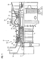
- FIG. 1 shows a stationary gas turbine 10 in a longitudinal partial section.
- the gas turbine 10 has inside a rotatably mounted about an axis of rotation 12 rotor 14, which is also referred to as a turbine runner.
- rotor 14 Along the rotor 14 follow one another an intake housing 16, a compressor 18, a toroidal annular combustion chamber 20 with a plurality of rotationally symmetrical mutually arranged burners 22, a turbine unit 24 and an exhaust housing 26.
- the compressor 18 comprises an annular compressor duct 25 with compressor stages of rotor blade and vane rings following each other in cascade.
- the rotor blades 14 arranged on the blades 27 are with their free-ending blade tips 29 an outer channel wall of the compressor passage 25 against.
- the compressor passage 25 opens via a compressor outlet diffuser 36 in a plenum 38.
- the annular combustion chamber 20 with her Combustion chamber 28 is provided which communicates with an annular hot gas channel 30 of the turbine unit 24.
- four successive turbine stages 32 are arranged.
- a generator or a working machine (each not shown) is coupled.
- the compressor 18 sucks through the intake housing 16 as a medium to be compressed ambient air 34 and compresses them.
- the compressed air is guided through the compressor outlet diffuser 36 into the plenum 38, from where it flows into the burner 22.
- Fuel also passes into the combustion space 28 via the burners 22.
- the fuel is burned to a hot gas M with the addition of the compressed air.
- the hot gas M then flows into the hot gas duct 30, where it relaxes to perform work on the turbine blades of the turbine unit 24.
- the energy released during this time is absorbed by the rotor 14 and used on the one hand to drive the compressor 18 and on the other hand to drive a work machine or electric generator.
- a compressor-side bearing 39 for supporting the rotor 14 is in FIG. 1 only shown schematically.
- the bearing 39 is shown in a longitudinal section in detail.
- the bearing 39 comprises a central bearing body 40, in which two thrust bearings 47, 49 and a radial bearing 41 are provided.
- the thrust bearings 47, 49 are designed as a main track bearing and as an auxiliary track bearing.
- the two thrust bearings 47, 49 are referred to below as the main track 47 or secondary track 49 or collectively as tracks 47, 49.
- All bearings 41, 47, 49 are designed as hydrodynamic plain bearings.
- the main track 47 comprises an element carrier 51 and a plurality of bearing elements 46 which are seated in it and distributed over the circumference, each having a bearing surface 50.
- the bearing surfaces 50 of the bearing elements 46 are the lateral rotor surface 42 immediately adjacent.
- the secondary track 49 comprises an element carrier 53 with a plurality of bearing elements 48 distributed over the circumference, each of which has a bearing surface 52 lying opposite the lateral rotor surface 44.
- the bearing elements 46, 48 can be pressed by axial force acting on the element carrier 51, 53 hydraulic fluid to the rotor surfaces 42, 44 for axial bearing of the rotor 14.
- a hydraulic system 60 ( FIG. 3 ) is provided, by means of which both at shifted and when not shifted rotor 14, an inventive damping of axial vibrations can be activated.
- This hydraulic system 60 comprises, in addition to a tank 62 for the hydraulic means 61, a conduit system for connecting the tank 62 to a supply terminal 64 of the main track 47 and a supply terminal 64 of the secondary track 49.
- For each track 47, 49 is a supply line 68, 70 with a plurality of Valves intended for control.
- a first pump P 1 may provide the hydraulic fluid 61 at a higher pressure p 1 than a second pump P 2 .
- the latter provides hydraulic means 61 with a lower pressure p 2 .
- the setting of the pressures p 1 , p 2 takes place with the aid of pressure-limiting valves 72, 74 whose input-side connections are connected to the output-side connections of the pumps P 1 , P 2 .
- the pressure relief valves 72, 74 return the excess hydraulic fluid 61 back to the tank 62.
- a 4/2-way valve V 12 which is connected to the input of the pump P 1 input side, hydraulic fluid 61 at a higher pressure p 1 with activated electric drive K 1 via a shuttle valve V 7 of the main track 47 or activated electric drive K 2nd via a shuttle valve V 8 of the secondary track 49 feed.
- V 3 , V 4 can with the occurrence or after the occurrence of impermissibly large Axialschwingungsamplituden of the rotor 14 not supplied with a high pressure p 1 track 47, 49 via the corresponding shuttle valve V 7 , V 8 hydraulic fluid 61 are supplied at a lower pressure p 2 .
- To activate the 3/2-way valves V3, V4 is the respective associated electric drive K 3 or K 4 to operate.
- valves V 3 , V 4 , V 5 , V 6 are reset by spring force with deactivated electrical drives K x .
- the electric drives are designed as electromagnetic coils.
- FIG. 4 also shows the electrical circuit diagram for controlling the electric drives K 1 to K 6 of the hydraulic system 60.
- the circuit diagram comprises six current paths SP1 to SP6.
- a switch S1 By operating a switch S1 is switched from a non-displaced rotor 14 operation to a shifted rotor 14 operation.
- a switch S2 By actuating a switch S2, the damping of the rotor 14 can be activated, which will be explained in more detail below.
- the gas turbine rotor 14 When starting up the gas turbine 10, the gas turbine rotor 14 is accelerated from 0 min -1 to rated speed. Meanwhile, and also during operation of the gas turbine 10 occur both in the compressor 18 and in the turbine unit 24 flow forces acting on the rotor 14. Their axial components are directed counter to each other and partially compensate each other. At start-up, the resulting axial flow force initially pushes the rotor 14 toward the intake housing 16. Only upon reaching an envelope speed slightly below the rated speed does the resulting axial thrust abruptly revolve, causing the rotor 14 to move toward the exhaust housing 26 pushes. Even in normal operation of the gas turbine, the rotor 14 of the flow forces of the hot gas M in this Pushed direction. This direction is referred to as the main thrust direction.
- a film of hydraulic fluid 54 is applied between the rotor 14 and the radial bearing 41.
- the two surfaces 44, 52 are only separated by a thin film of a hydraulic medium, for example hydraulic oil or turbine oil, for its axial bearing.
- the rotor 14 and the secondary track 49 are then frictionally connected, whereas between the bearing surface 50 and the rotor surface 42, an air gap (not in FIG. 2 shown) is present. This means that a frictional coupling of the main track 47 with the rotor 14 is then not given.
- the axial bearing changes from the secondary track 49 to the main track 47.
- a hydrodynamically acting film forms from the hydraulic medium between the bearing surface 50 and the rotor surface 42.
- the secondary track 49 is unloaded by an air gap 55 between the bearing surface 52 and rotor surface 44 occurs (shown in FIG. 2 ).
- the bearing member 46 is axially displaceable for adjusting radial gaps, wherein the axial displacement in the bearing 39, an oil chamber 56 is arranged, which is fed by pressing the switch S1 hydraulic oil at a higher pressure p 1 , so that a synchronous axial displacement of element carrier 51 and Bearing elements 46 is achieved.
- the higher pressure p 1 is achieved in that the pressure relief valve 72 is set accordingly.
- the element carrier 51 has to the oil chamber 56 toward an inner diameter and an outer diameter in each case a sealing ring. Also the bearing element 48 and cooperating with him element carrier 53 are also formed axially displaceable.
- the secondary track 49 as a second thrust bearing 45 by simultaneously supplying the hydraulic fluid in the gap between the bearing surface 52 and rotor surface 44 are frictionally coupled with the aim of reducing the axial play of the rotor 14.
- a large pressure in the hydraulic means of the second track bearing 45 is required that an additionally acting in the main thrust direction of the rotor 14 force is generated from the second thrust bearing 45 via the rotor 14 to the first thrust bearing 43.
- the method is not only applicable to gas turbines, but also in other rotary machines.
- the invention thus relates to a method for operating a rotary machine with a stored in a bearing 39 rotor 14, which rotor 14 is exposed to an operating time of a mainly acting in only one axial thrust and thrust of a first thrust bearing 43 of the bearing 39 via lubricant is received and derived, wherein the bearing 39 has a second thrust bearing 45.
- a thrust acting force is generated on the first thrust bearing 43.
Landscapes
- Engineering & Computer Science (AREA)
- General Engineering & Computer Science (AREA)
- Mechanical Engineering (AREA)
- Support Of The Bearing (AREA)
- Magnetic Bearings And Hydrostatic Bearings (AREA)
Description
- Die Erfindung betrifft ein Verfahren zum Betrieb einer Rotationsmaschine gemäß dem Oberbegriff des Anspruchs 1.
- Eine gattungsgemäße Rotationsmaschine ist beispielsweise in der
WO 00/28190 A1 EP 1 479 875 A1 bekannt. Dabei kann mit Hilfe eines 4/2-Wegeventils entweder die Hauptspur oder die Nebenspur druckbeaufschlagt werden, je nachdem, ob der Rotor axial verschoben werden soll oder nicht. - Dazu alternative Axiallager gehen aus
WO 91/02174 A1 US 5,795,073 hervor. - Im bestimmungsgemäßen Betrieb der Gasturbine liegt die Seitenfläche des ersten Wellenbunds an der Hauptspur des Axiallagers an, da die im Turbinenbereich auf den Rotor axial einwirkenden Strömungskräfte des Heißgases größer sind als die Strömungskräfte im Verdichter und somit diesen stetig vom Verdichter in Richtung Turbineneinheit schieben. Die Nebenspur ist anstelle der Hauptspur dann im Kraftfluss des Axiallagers, wenn der Rotor der Gasturbine vom Stillstand auf Nenndrehzahl beschleunigt wird. Während dieses Hochfahrens tritt eine auf den Gasturbinenrotor axial wirkende resultierende Schubkraft auf, die entgegengesetzt zur Betriebs-Schubkraft gerichtet ist, nämlich von der Turbineneinheit in Richtung Verdichter. Etwas vor Erreichen der Nenndrehzahl ändert sich die aktuelle Schubrichtung schlagartig, so dass dann die Axialpositionierung des Rotors von der Nebenspur auf die Hauptspur wechselt.
- Das vorbekannte Axiallager ist zudem mit axial verschieblichen Lagerelementen ausgestattet, um den Rotor während des stationären Betriebs der Gasturbine entgegen der Strömungsrichtung des Heißgases zu verschieben und damit Radialspalte in der Turbine zwischen Laufschaufelspitzen und einer diesen gegenüberliegenden Gehäusewand zu minimieren.
- Es hat sich gezeigt, dass Betriebszustände beim Betrieb der Gasturbine auftreten können, die zu Axialschwingungen des Rotors führen. Diese Axialschwingungen können schlechtestenfalls zur Schädigung des Axiallagers oder von im Kraftfluss befindlichen Bauteilen führen, sofern die Amplituden der Axialschwingungen eine kritische Größe überschreiten. Die Axialschwingungen werden zumeist durch einen innerhalb der Brennkammer ablaufenden instabilen Verbrennungsprozess hervorgerufen. Die Ursachen der Instabilität sind häufig vielfältig und nicht kausal vorhersagbar.
- Aufgabe der Erfindung ist daher die Bereitstellung eines Verfahrens zum Betrieb einer Rotationsmaschine, bei welchem die Axialschwingungen des Rotors gedämpft oder gar vermieden werden.
- Die auf das Verfahren gerichtete Aufgabe wird mit einem solchen gemäß den Merkmalen des Anspruchs 1 gelöst. Vorteilhafte Ausgestaltungen und weitere Merkmale der Erfindung sind in den Unteransprüchen angegeben.
- Beim erfindungsgemäßen Verfahren zum Betrieb einer Rotationsmaschine mit einem in einem Lager gelagerten Rotor, welcher Rotor zu einem Betriebszeitpunkt einer hauptsächlich in nur einer Axialrichtung - d.h. Hauptschubrichtung - wirkenden Schubkraft ausgesetzt ist und welche Schubkraft von einem ersten Spurlager des Lagers über Gleitmittel aufgenommen und abgeleitet wird, wobei das Lager ein zweites Spurlager aufweist, wird während dem Auftreten der Schubkraft zumindest zeitweise gleichzeitig das zweite Spurlager so angesteuert, dass es über den Rotor eine in Hauptschubrichtung wirkende Kraft auf das erste Spurlager erzeugt.
- Die Erfinder haben erkannt, dass mit Hilfe der jeweils unbelasteten Spur - also dem zweiten Spurlager - die Möglichkeit besteht, beim Auftreten von Axialschwingungen auch das zweite Spurlager in Eingriff mit dem Rotor zu bringen und dadurch eine Dämpfung der Axialschwingungen über die Reduktion des Axialspiels an der belasteten - also dem ersten Spurlager - zu erreichen. Insofern wird der Rotor der Rotationsmaschine trotz Vorhandensein einer zum Zeitpunkt in nur einer Axialrichtung wirkenden Schubkraft zusätzlich mit einer weiteren, in der gleichen Richtung wirkenden Kraft beaufschlagt, um die Neigung des Rotors zum Schwingen zu verringern. Obwohl dadurch das erste Spurlager mit einer höheren Kraft beaufschlagt wird als durch die Schubkraft erzeugt, wird es üblicherweise dadurch nicht überlastet. Mit dem Verfahren kann sichergestellt werden, dass zwar nicht die Ursache der Axialschwingungen des Rotors, jedoch deren Eigenschaften signifikant verändert werden: die Amplitude der Axialschwingungen wird begrenzt. Dies vermeidet zuverlässig Schädigungen des Lagers oder von im Kraftfluss befindlichen Bauteilen.
- Vorzugsweise ist das Lager und somit die beiden Spurlager jeweils als hydrodynamisches Gleitlager ausgestaltet, bei dem die kraftschlüssige Kopplung von Spurlager und Rotor durch das Einspeisen eines Hydrauliköls in den zwischen Spurlager und Rotor vorhandenen Axialspalt erreicht wird.
- Besonders bevorzugt wird das Verfahren während eines instationären Betriebszustands und/oder während eines Teillastbetriebs einer als Turbomaschine ausgestalteten Rotationsmaschine durchgeführt. Insbesondere bei stationären Gasturbinen, bei denen üblicherweise eine in Axialrichtung wirkende Schubkraft auf den Rotor auftritt, können bei instationären Betriebszuständen, wie z.B. dem Anfahren der Gasturbine aus dem Stillstand bis auf Nenndrehzahl, Axialschwingungen auftreten. Auch bei niedriger Teillast können derartige Schwingungszustände auftreten. Insofern ist es von Vorteil, wenn lediglich während dieser Betriebszustände auch das zweite Spurlager kraftschlüssig mit dem Rotor verbunden ist. Üblicherweise ist im Volllastbetrieb das zweite Spurlager nicht kraftschlüssig an den Rotor gekoppelt, sondern lediglich nur das erste Spurlager, da in diesem Betriebszustand Axialschwingungen in der Regel nicht auftreten. Das spart die zur Versorgung des zweiten Spurlagers mit Hydraulikmittel benötigte Energie.
- Weiter bevorzugt werden die Axialschwingungen des Rotors von einem Messaufnehmer erfasst und mit einem Grenzwert verglichen. Vorzugszweise wird erst bei Grenzwertüberschreitungen die vorgeschlagene Dämpfung des Rotors aktiviert, indem gleichzeitig das zweite Spurlager so angesteuert, dass es über den Rotor eine in Hauptschubrichtung wirkende Kraft auf das erste Spurlager erzeugt.
- Selbstverständlich ist das Verfahren auch durchführbar vor, während und/oder nach einer Axialverschiebung des Rotors.
- Die Erfindung wird nachfolgend anhand eines hydraulischen Axiallagers beschrieben. Selbstverständlich ist es auch möglich, die beiden Spuren des Axiallager durch zwei entgegengesetzt wirkende magnetische Axiallager zu ersetzen, die entsprechend der Erfindung gleichzeitig entgegengesetzte Schubkräfte auf den zu lagernden Rotor beim Auftreten von Axialschwingungen erzeugen können.
- Weitere Vorteile und Merkmale der Erfindung ergeben sich aus einem Ausführungsbeispiel, welches in den angehangenen Figuren näher beschrieben ist. Es zeigen:
- FIG 1
- eine stationäre Gasturbine in einem Längsteilquerschnitt,
- FIG 2
- einen Längsschnitt durch ein Lager einer Rotationsmaschine mit einem ersten und einem zweiten Spurlager,
- FIG 3
- das Hydrauliksystem zur Betätigung des hydraulischen Axiallagers nach
FIG 2 und - FIG 4
- einen elektrischen Schaltplan zu Ansteuerung des Hydrauliksystems nach
FIG 3 . - In allen Figuren sind identische Merkmale mit den gleichen Bezugszeichen versehen.
-
Figur 1 zeigt eine stationäre Gasturbine 10 in einem Längsteilschnitt. Die Gasturbine 10 weist im Innern einen um eine Rotationsachse 12 drehgelagerten Rotor 14 auf, der auch als Turbinenläufer bezeichnet wird. Entlang des Rotors 14 folgen aufeinander ein Ansauggehäuse 16, ein Verdichter 18, eine torusartige Ringbrennkammer 20 mit mehreren rotationssymmetrisch zueinander angeordneten Brennern 22, eine Turbineneinheit 24 und ein Abgasgehäuse 26. - Der Verdichter 18 umfasst einen ringförmig ausgebildeten Verdichterkanal 25 mit darin kaskadisch aufeinanderfolgenden Verdichterstufen aus Laufschaufel- und Leitschaufelkränzen. Die am Rotor 14 angeordneten Laufschaufeln 27 liegen mit ihren frei endenden Schaufelblattspitzen 29 einer äußeren Kanalwand des Verdichterkanals 25 gegenüber. Der Verdichterkanal 25 mündet über einen Verdichterausgangsdiffusor 36 in einem Plenum 38. Darin ist die Ringbrennkammer 20 mit ihrem Verbrennungsraum 28 vorgesehen, der mit einem ringförmigen Heißgaskanal 30 der Turbineneinheit 24 kommuniziert. In der Turbineneinheit 24 sind vier hintereinander geschaltete Turbinenstufen 32 angeordnet. Am Rotor 14 ist ein Generator oder eine Arbeitsmaschine (jeweils nicht dargestellt) angekoppelt.
- Im Betrieb der Gasturbine 10 saugt der Verdichter 18 durch das Ansauggehäuse 16 als zu verdichtendes Medium Umgebungsluft 34 an und verdichtet diese. Die verdichtete Luft wird durch den Verdichterausgangsdiffusor 36 in das Plenum 38 geführt, von wo aus es in die Brenner 22 einströmt. Über die Brenner 22 gelangt auch Brennstoff in den Verbrennungsraum 28. Dort wird der Brennstoff unter Zugabe der verdichteten Luft zu einem Heißgas M verbrannt. Das Heißgas M strömt anschließend in den Heißgaskanal 30, wo es sich arbeitsleistend an den Turbinenschaufeln der Turbineneinheit 24 entspannt. Die währenddessen freigesetzte Energie wird vom Rotor 14 aufgenommen und einerseits zum Antrieb des Verdichters 18 und andererseits zum Antrieb einer Arbeitsmaschine oder elektrischen Generators genutzt.
- Ein verdichterseitiges Lager 39 zur Lagerung des Rotors 14 ist in
Figur 1 lediglich schematisch dargestellt. - In
FIG 2 ist das Lager 39 in einem Längsschnitt im Detail dargestellt. Das Lager 39 umfasst einen zentralen Lagerkörper 40, in dem zwei Axiallager 47, 49 und ein Radiallager 41 vorgesehen sind. Die Axiallager 47, 49 sind dabei als Hauptspurlager und als Nebenspurlager ausgebildet. Die beiden Axiallager 47, 49 werden nachfolgend kurz als Hauptspur 47 bzw. Nebenspur 49 oder gemeinsam als Spuren 47, 49 bezeichnet. Alle Lager 41, 47, 49 sind als hydrodynamische Gleitlager ausgebildet. - Die Hauptspur 47 umfasst einen Elementträger 51 und mehrere darin sitzende, über den Umfang verteilte Lagerelemente 46, welche jeweils eine Lagerfläche 50 besitzen. Die Lagerflächen 50 der Lagerelemente 46 sind der seitlichen Rotorfläche 42 unmittelbar benachbart. Ebenso umfasst die Nebenspur 49 einen Elementträger 53 mit mehreren, über den Umfang verteilten Lagerelementen 48, die jeweils eine der seitlichen Rotorfläche 44 gegenüberliegende Lagerfläche 52 besitzen. Die Lagerelemente 46, 48 können dabei durch auf die Elementträger 51, 53 einwirkendes Hydraulikmittel an die Rotorflächen 42, 44 zur Axiallagerung des Rotors 14 angepresst werden.
- Zur Betätigung der beiden Spurlager 43, 45 ist ein Hydrauliksystem 60 (
FIG 3 ) vorgesehen, mittels welchem sowohl bei verschobenem als auch bei nicht verschobenem Rotor 14 eine erfindungsgemäße Dämpfung von Axialschwingungen aktivierbar ist. Dieses Hydrauliksystem 60 umfasst neben einem Tank 62 für das Hydraulikmittel 61 ein Leitungssystem zum Verbinden des Tanks 62 mit einem Versorgungsanschluss 64 der Hauptspur 47 und einem Versorgungsanschluss 64 der Nebenspur 49. Für jede Spur 47, 49 ist eine Versorgungsleitung 68, 70 mit einer Vielzahl an Ventilen zur Steuerung vorgesehen. Eine erste Pumpe P1 kann das Hydraulikmittel 61 mit einem höheren Druck p1 bereitstellen als eine zweite Pumpe P2. Letztere stellt Hydraulikmittel 61 mit einem geringeren Druck p2 bereit. Die Einstellung der Drücke p1, p2 erfolgt mit Hilfe von Druckbegrenzungsventilen 72, 74, deren eingangsseitigen Anschlüsse mit den ausgangsseitigen Anschlüssen der Pumpen P1, P2 verbunden sind. Die Druckbegrenzungsventile 72, 74 führen das überschüssige Hydraulikmittel 61 zurück in den Tank 62. - Ein 4/2-Wegeventil V12, welches mit den Ausgang der Pumpe P1 eingangsseitig verbunden ist, kann Hydraulikmittel 61 mit höherem Druck p1 bei aktiviertem elektrischem Antrieb K1 über ein Wechselventil V7 der Hauptspur 47 oder bei aktiviertem elektrischem Antrieb K2 über ein Wechselventil V8 der Nebenspur 49 zuführen. Mit Hilfe von zwei 3/2-Wegeventilen V3, V4 kann mit dem Auftreten oder nach dem Auftreten von unzulässig großen Axialschwingungsamplituden des Rotors 14 die nicht mit einem hohen Druck p1 versorgte Spur 47, 49 über das entsprechende Wechselventil V7, V8 Hydraulikmittel 61 mit niedrigerem Druck p2 zugeführt werden. Zur Aktivierung der 3/2-Wegeventile V3, V4 ist der jeweils zugehörige elektrische Antrieb K3 bzw. K4 zu betätigen.
- Aus den Spuren 47, 49 zurückfließendes Hydraulikmittel, was bei der Deaktivierung der Axialverschiebung des Rotors 14 oder bei der Deaktivierung der Dämpfung auftritt, wird über die zu den Wechselventilen V7 und V8 jeweils parallelgeschalteten 2/2-Wegenventile V5, V6 und anschließend über das 4/2-Wegeventil V12 in den Tank 62 zurückgeführt.
- Die Ventile V3, V4, V5, V6 werden über Federkraft zurückgestellt bei deaktivierten, elektrischen Antrieben Kx. Üblicherweise sind die elektrischen Antriebe als elektromagnetische Spulen ausgebildet.
-
FIG 4 zeigt zudem das elektrische Schaltbild zur Ansteuerung der elektrischen Antriebe K1 bis K6 des Hydrauliksystems 60. Das Schaltbild umfasst sechs Strompfade SP1 bis SP6. Durch Betätigen eines Schalters S1 wird von einem Betrieb mit nicht verschobenem Rotor 14 zu einem Betrieb mit verschobenem Rotor 14 umgeschaltet. Durch die Betätigung eines Schalters S2 kann die Dämpfung des Rotors 14 aktiviert werden, was nachfolgend noch näher erläutert wird. - Beim Hochfahren der Gasturbine 10 wird der Gasturbinenrotor 14 von 0 min-1 bis auf Nenndrehzahl beschleunigt. Währenddessen und auch im Betrieb der Gasturbine 10 treten sowohl im Verdichter 18 als auch in der Turbineneinheit 24 Strömungskräfte auf, die auf den Rotor 14 einwirken. Deren axialen Komponenten sind einander gegengerichtet und kompensieren sich teilweise. Beim Hochfahren schiebt die resultierende axiale Strömungskraft den Rotor 14 anfänglich in Richtung des Ansauggehäuses 16. Erst mit dem Erreichen einer UmschlagDrehzahl, die etwas unterhalb der Nenndrehzahl liegt, dreht sich die resultierende axiale Schubkraft schlagartig um, so dass der Rotor 14 dann in Richtung Abgasgehäuse 26 schiebt. Auch im bestimmungsgemäßen Betrieb der Gasturbine wird der Rotor 14 von den Strömungskräften des Heißgases M in diese Richtung geschoben. Diese Richtung wird als Hauptschubrichtung bezeichnet.
- Während des Hochfahrens und auch im Betrieb der Gasturbine 10 liegt ein Film aus Hydraulikmittel 54 zwischen dem Rotor 14 und dem Radiallager 41 an.
Solange der Rotor 14 entgegen der Hauptschubrichtung schiebt, sind zu dessen Axiallagerung die beiden Flächen 44, 52 lediglich durch einen dünnen Film aus einem Hydraulikmittel, beispielsweise Hydrauliköl oder Turbinenöl, getrennt. Der Rotor 14 und die Nebenspur 49 sind dann kraftschlüssig verbunden, wohingegen zwischen der Lagerfläche 50 und der Rotorfläche 42 ein Luftspalt (nicht inFIG 2 dargestellt) vorhanden ist. Dies bedeutet, dass eine kraftschlüssige Kopplung der Hauptspur 47 mit dem Rotor 14 dann nicht gegeben ist. - Nach dem Erreichen der Umschlag-Drehzahl wechselt die Axiallagerung von der Nebenspur 49 auf die Hauptspur 47. Dazu bildet sich zwischen Lagerfläche 50 und Rotorfläche 42 ein hydrodynamisch wirkender Film aus dem Hydraulikmittel aus. Gleichzeitig wird die Nebenspur 49 unbelastet, indem ein Luftspalt 55 zwischen Lagerfläche 52 und Rotorfläche 44 auftritt (dargestellt in
FIG 2 ). - Zu diesem Zeitpunkt ist weder Schalter S1 noch Schalter S2 betätigt, so über den Stromkreis SP2 allein Antrieb K2 aktiviert ist.
- Das Lagerelement 46 ist zur Einstellung von Radialspalten axial verschieblich, wobei zur Axialverschiebung in dem Lager 39 ein Ölraum 56 angeordnet ist, dem durch Betätigen des Schalters S1 Hydrauliköl mit einem höheren Druck p1 einspeisbar ist, so dass eine synchrone axiale Verschiebung von Elementträger 51 und Lagerelementen 46 erreicht wird. Der höhere Druck p1 wird dadurch erreicht, dass das Druckbegrenzungsventil 72 entsprechend eingestellt ist. Der Elementträger 51 weist zum Ölraum 56 hin an einem Innendurchmesser und einem Außendurchmesser jeweils einen Dichtring auf. Auch das Lagerelement 48 und der mit ihm zusammenwirkende Elementträger 53 sind ebenso axialverschieblich ausgebildet.
- Für den Fall, dass der Rotor 14 aufgrund von Verbrennungsinstabilitäten im Teillastbetrieb der Gasturbine 10 zu Axialschwingungen neigt, kann zusätzlich zu der im Kraftfluss befindlichen (belasteten) Hauptspur 47 als erstes Spurlager 43 die Nebenspur 49 als zweites Spurlager 45 durch gleichzeitiges Zuführen des Hydraulikmittels auch in den Spalt zwischen Lagerfläche 52 und Rotorfläche 44 kraftschlüssig gekoppelt werden mit dem Ziel, das Axialspiel des Rotors 14 zu verringern. Dazu ist ein derartig großer Druck im Hydraulikmittel des zweiten Spurlagers 45 erforderlich, dass eine zusätzlich in Hauptschubrichtung des Rotors 14 wirkende Kraft vom zweiten Spurlager 45 über den Rotor 14 auf das erste Spurlager 43 erzeugt wird. Diese Kraft dämpft und begrenzt beim Auftreten von Axialschwingungen das Zurückpendeln des Rotors 14 entgegen der Strömungsrichtung des Heißgases M. Dadurch können Schädigungen sowohl am Rotor 14 als auch an den im Kraftschluss befindlichen Lagerbauteilen der Gasturbine 10 sicher vermieden werden. Um dies zu erreichen, wird S2 manuell oder selbsttätig bei Überschreiten einer unzulässig großen Axialschwingung betätigt, wodurch der Antrieb K4 dann das Ventil V4 betätigt. Nach der Beendigung des Axialschwingungsdämpfungsschrittes wird S2 deaktiviert, wodurch der Antrieb K6 das Ventil V6 betätigt. Dadurch kann das Hydraulikmittel der Nebenspur 49 über die Leitung 70, die Ventil V6 und V12 in den Tank 62 abfließen.
Sofern während des Hochfahrens Axialschwingungen auftreten, können diese gedämpft werden, indem zu der bereits belasteten Nebenspur 49 die Hauptspur 47 zugeschaltet wird. In diesem Fall ist der Schalter S1 unbetätigt und der Schalter S2 betätigt. Die Hauptspur 47 erzeugt dann eine zusätzliche Kraft, welche über den Rotor 14 die Nebenspur 49 weiter belastet. - Selbstverständlich ist das Verfahren nicht nur bei Gasturbinen anwendbar, sondern auch bei anderen Rotationsmaschinen. Insgesamt betrifft die Erfindung somit ein Verfahren zum Betrieb einer Rotationsmaschine mit einem in einem Lager 39 gelagerten Rotor 14, welcher Rotor 14 zu einem Betriebszeitpunkt einer hauptsächlich in nur einer Axialrichtung wirkenden Schubkraft ausgesetzt ist und welche Schubkraft von einem ersten Spurlager 43 des Lagers 39 über Gleitmittel aufgenommen und abgeleitet wird, wobei das Lager 39 ein zweites Spurlager 45 aufweist. Um Verfahren anzugeben, bei welchem die Axialschwingungen des Rotors 14 gedämpft oder gar vermieden werden, wird vorgeschlagen, dass während dem Auftreten der Schubkraft zumindest zeitweise gleichzeitig das zweite Spurlager 45 eine in Schubrichtung wirkende Kraft auf das erste Spurlager 43 erzeugt wird. Hierdurch wird der Rotor 14 - in Axialrichtung gesehen -verspannt, wobei er währenddessen selbstverständlich weiterhin drehbar gelagert ist.
Claims (6)
- Verfahren zum Betrieb einer Rotationsmaschine mit einem in einem Lager (39) gelagerten Rotor (14),
welcher Rotor (14) zu einem Betriebszeitpunkt einer hauptsächlich in nur einer Axialrichtung wirkenden Schubkraft ausgesetzt ist und welche Schubkraft von einem ersten Spurlager (43) des Lagers (39) über Gleitmittel aufgenommen und abgeleitet wird,
wobei das Lager (39) ein zweites Spurlager (45) aufweist, gekennzeichnet durch den Schritt,
dass während dem Auftreten der Schubkraft
zumindest zeitweise gleichzeitig das zweite Spurlager (45) eine in Schubrichtung wirkende Kraft auf das erste Spurlager (43) erzeugt. - Verfahren nach Anspruch 1,
bei dem erst nach bzw. mit dem Auftreten von Axialschwingungen des Rotors (14) die in Hauptschubrichtung wirkende Kraft aktiviert wird. - Verfahren nach Anspruch 1 oder 2,
welches während instationären Betriebszuständen und/oder während eines Teillastbetriebs einer als Turbomaschine ausgestalteten Rotationsmaschine durchgeführt wird. - Verfahren nach Anspruch 4,
welches bei einer als stationäre Gasturbine (10) ausgestalteten Turbomaschine durchgeführt wird. - Verfahren nach einem der vorangehenden Ansprüche,
welches vor und/oder während einer Axialverschiebung des Rotors (14) durchgeführt wird. - Verfahren, bei dem das Lager als hydraulisches Axiallager ausgestaltet ist.
Priority Applications (1)
| Application Number | Priority Date | Filing Date | Title |
|---|---|---|---|
| EP12742844.9A EP2721258B1 (de) | 2011-07-21 | 2012-07-23 | Verfahren zum betrieb einer rotationsmaschine |
Applications Claiming Priority (3)
| Application Number | Priority Date | Filing Date | Title |
|---|---|---|---|
| EP11174791A EP2549059A1 (de) | 2011-07-21 | 2011-07-21 | Verfahren zum Betrieb einer Rotationsmaschine |
| PCT/EP2012/064411 WO2013011150A1 (de) | 2011-07-21 | 2012-07-23 | Verfahren zum betrieb einer rotationsmaschine |
| EP12742844.9A EP2721258B1 (de) | 2011-07-21 | 2012-07-23 | Verfahren zum betrieb einer rotationsmaschine |
Publications (2)
| Publication Number | Publication Date |
|---|---|
| EP2721258A1 EP2721258A1 (de) | 2014-04-23 |
| EP2721258B1 true EP2721258B1 (de) | 2015-06-24 |
Family
ID=46603915
Family Applications (2)
| Application Number | Title | Priority Date | Filing Date |
|---|---|---|---|
| EP11174791A Withdrawn EP2549059A1 (de) | 2011-07-21 | 2011-07-21 | Verfahren zum Betrieb einer Rotationsmaschine |
| EP12742844.9A Active EP2721258B1 (de) | 2011-07-21 | 2012-07-23 | Verfahren zum betrieb einer rotationsmaschine |
Family Applications Before (1)
| Application Number | Title | Priority Date | Filing Date |
|---|---|---|---|
| EP11174791A Withdrawn EP2549059A1 (de) | 2011-07-21 | 2011-07-21 | Verfahren zum Betrieb einer Rotationsmaschine |
Country Status (6)
| Country | Link |
|---|---|
| US (1) | US9494046B2 (de) |
| EP (2) | EP2549059A1 (de) |
| JP (1) | JP5792387B2 (de) |
| CN (1) | CN103688022B (de) |
| RU (1) | RU2601067C2 (de) |
| WO (1) | WO2013011150A1 (de) |
Families Citing this family (5)
| Publication number | Priority date | Publication date | Assignee | Title |
|---|---|---|---|---|
| EP2873880A1 (de) | 2013-11-13 | 2015-05-20 | Siemens Aktiengesellschaft | Nicht symmetrisches bidirektionales Drucklager mit zwei aktiven Flächen |
| EP3250834B1 (de) | 2015-01-30 | 2021-01-20 | Siemens Aktiengesellschaft | Kippsegmentenlager zur lagerung eines rotorzapfens in einem turbinenmotor |
| WO2018056709A1 (ko) * | 2016-09-22 | 2018-03-29 | 엘지전자 주식회사 | 영상 코딩 시스템에서 인터 예측 방법 및 장치 |
| EP3760886A1 (de) * | 2019-07-03 | 2021-01-06 | Siemens Aktiengesellschaft | Lageranordnung für ein axiallager |
| DE102020212567A1 (de) | 2020-10-06 | 2022-04-07 | Siemens Energy Global GmbH & Co. KG | Lager, Gasturbineneinheit mit einem solchen Lager sowie Verfahren zum Betreiben einer Gasturbineneinheit |
Family Cites Families (24)
| Publication number | Priority date | Publication date | Assignee | Title |
|---|---|---|---|---|
| US3192000A (en) * | 1963-05-10 | 1965-06-29 | John G Williams | Force balance hydrostatic-hydrodynamic thrust bearing |
| US3895689A (en) * | 1970-01-07 | 1975-07-22 | Judson S Swearingen | Thrust bearing lubricant measurement and balance |
| DE2357881A1 (de) * | 1973-11-16 | 1975-05-22 | Mannesmann Meer Ag | Hydraulisch beaufschlagtes axialdrucklager |
| US4273390A (en) * | 1978-05-15 | 1981-06-16 | Rotoflow Corporation | Bearing system with thrust compensation means |
| CA1232855A (en) | 1982-07-22 | 1988-02-16 | Tsoung-Yuan | Hydroisomerization of catalytically dewaxed lubricating oils |
| DE3433351C1 (de) * | 1984-09-11 | 1986-01-02 | MTU Motoren- und Turbinen-Union München GmbH, 8000 München | Kapazitives Messsystem zur Messung des Abstandes zwischen zwei relativ zueinander beweglichen Teilen |
| JPH0266316A (ja) | 1988-07-29 | 1990-03-06 | General Electric Co <Ge> | スラスト軸受潤滑装置 |
| SE464370B (sv) | 1989-07-27 | 1991-04-15 | Desart Ab | Foer en radiellt lagrad axel avsett axiallagringssystem |
| US5248239A (en) * | 1992-03-19 | 1993-09-28 | Acd, Inc. | Thrust control system for fluid handling rotary apparatus |
| US5795073A (en) * | 1993-09-17 | 1998-08-18 | Arvidsson; Thomas | Radial and thrust bearing system |
| DE4445957A1 (de) * | 1994-12-22 | 1996-06-27 | Abb Management Ag | Verfahren und Vorrichtung zur Eigenschmierung der Wälzlager von Turbomaschinen |
| US6067791A (en) | 1997-12-11 | 2000-05-30 | Pratt & Whitney Canada Inc. | Turbine engine with a thermal valve |
| WO2000028190A1 (de) | 1998-11-11 | 2000-05-18 | Siemens Aktiengesellschaft | Wellenlager für eine strömungsmaschine, strömungsmaschine sowie verfahren zum betrieb einer strömungsmaschine |
| WO2002004827A1 (en) * | 2000-07-10 | 2002-01-17 | Bently Nevada Corporation | A hydrostatic bearing for use in a turbocharger |
| JP2002095212A (ja) * | 2000-09-12 | 2002-03-29 | Sumitomo Electric Ind Ltd | スピンドルモータの耐振構造 |
| JP4245897B2 (ja) | 2002-10-24 | 2009-04-02 | Ntn株式会社 | 動圧軸受装置の製造方法 |
| EP1479875A1 (de) * | 2003-05-23 | 2004-11-24 | Siemens Aktiengesellschaft | Lager für die axiale Lagerung eines Läufers einer Gasturbine |
| EP1524411B1 (de) | 2003-10-13 | 2011-07-20 | Siemens Aktiengesellschaft | Turbine und Verfahren zur Minimierung des Spaltes zwischen einer Laufschaufel und einem Gehäuse einer Turbine |
| JP2005121114A (ja) * | 2003-10-16 | 2005-05-12 | Canon Inc | スピンドル装置 |
| US7108488B2 (en) | 2004-03-26 | 2006-09-19 | Honeywell International, Inc. | Turbocharger with hydrodynamic foil bearings |
| JP2007271009A (ja) | 2006-03-31 | 2007-10-18 | Matsushita Electric Ind Co Ltd | 流体軸受回転装置および記録再生装置 |
| ITMI20072442A1 (it) * | 2007-12-28 | 2009-06-29 | Ansaldo Energia Spa | Gruppo cuscinetto per una turbina a gas |
| JP5109690B2 (ja) | 2008-01-31 | 2012-12-26 | 日本電産株式会社 | 流体動圧軸受装置、スピンドルモータ、ディスク駆動装置、および軸受装置の製造方法 |
| CN101383536B (zh) | 2008-10-24 | 2010-12-22 | 大连电机集团有限公司 | 轴向大载荷永磁直驱电机 |
-
2011
- 2011-07-21 EP EP11174791A patent/EP2549059A1/de not_active Withdrawn
-
2012
- 2012-07-23 US US14/233,514 patent/US9494046B2/en active Active
- 2012-07-23 RU RU2014106549/06A patent/RU2601067C2/ru not_active IP Right Cessation
- 2012-07-23 CN CN201280036184.6A patent/CN103688022B/zh active Active
- 2012-07-23 EP EP12742844.9A patent/EP2721258B1/de active Active
- 2012-07-23 WO PCT/EP2012/064411 patent/WO2013011150A1/de not_active Ceased
- 2012-07-23 JP JP2014520690A patent/JP5792387B2/ja active Active
Also Published As
| Publication number | Publication date |
|---|---|
| RU2014106549A (ru) | 2015-09-10 |
| US9494046B2 (en) | 2016-11-15 |
| CN103688022A (zh) | 2014-03-26 |
| EP2721258A1 (de) | 2014-04-23 |
| WO2013011150A1 (de) | 2013-01-24 |
| JP2014527136A (ja) | 2014-10-09 |
| JP5792387B2 (ja) | 2015-10-14 |
| CN103688022B (zh) | 2016-01-06 |
| RU2601067C2 (ru) | 2016-10-27 |
| EP2549059A1 (de) | 2013-01-23 |
| US20140147247A1 (en) | 2014-05-29 |
Similar Documents
| Publication | Publication Date | Title |
|---|---|---|
| EP1131537B1 (de) | Verfahren zum betrieb einer strömungsmaschine | |
| DE60133629T2 (de) | Verfahren zum betrieb einer gasturbine mit verstellbaren leitschaufeln | |
| EP2011963B1 (de) | Verfahren zum Betrieb einer Gasturbine mit Axialschubausgleich | |
| CH706862A2 (de) | Labyrinthdichtungsdesign und aktive Spaltsteuerungsstrategie für Turbomaschinen. | |
| EP2017435A2 (de) | Turbomaschine mit elektrischer Maschine und Magnetlagern | |
| DE102018124206B4 (de) | Untersetzungsgetriebe | |
| EP1795725B1 (de) | Gasturbine mit geregelter Luftkühlung | |
| EP2824288B1 (de) | Flugtriebwerk | |
| WO2013011150A1 (de) | Verfahren zum betrieb einer rotationsmaschine | |
| CH708441A2 (de) | Systeme und Verfahren betreffend die axiale Positionierung von Turbinengehäusen und den Schaufelspitzenspalt in Gasturbinen. | |
| EP2723993B1 (de) | Verfahren zum hochfahren einer stationären gasturbine | |
| DE102006040757A1 (de) | Fluidrückführung im Trennkörper von Strömungsarbeitsmaschinen mit Nebenstromkonfiguration | |
| EP2458181A1 (de) | Verfahren zum Betreiben einer Gasturbine, Vorrichtung zum Regeln des Betriebs einer Gasturbine und Kraftwerk | |
| WO2003076780A1 (de) | Verfahren zum betreiben einer turbine | |
| EP1654442A1 (de) | Flugtriebwerk | |
| DE102018106564B4 (de) | Planetengetriebe, Gasturbinentriebwerk mit Planetengetriebe und Verfahren zum Herstellen eines Planetengetriebes | |
| WO2007051443A1 (de) | Turbomaschine mit einem zuganker bestehend aus zug- und druckhülsen | |
| CH705822B1 (de) | Axialverdichter für eine Strömungsmaschine, insbesondere eine Gasturbine. | |
| DE102019204507A1 (de) | Gleitlagervorrichtung, ein Verfahren zum Betrieb einer Gleitlagervorrichtung und ein Gasturbinentriebwerk | |
| DE69104324T2 (de) | Wegziehbare axiale Lagereinheit mit flexibler Membran für eine rotierende Maschine. | |
| DE19907907A1 (de) | Mehrstufiger Turboverdichter | |
| EP2394029A2 (de) | Turbomaschine mit einem ausgleichskolben | |
| WO2018206157A1 (de) | Lageranordnung zur lagerung eines turbinenrotors einer turbomaschine | |
| EP4034756B1 (de) | Gasturbinentriebwerk eines luftfahrzeuges mit einem getriebe | |
| DE102004042258B3 (de) | Verfahren zur Herstellung eines Konturspalts sowie Strömungsmaschine mit einem Konturspalt |
Legal Events
| Date | Code | Title | Description |
|---|---|---|---|
| PUAI | Public reference made under article 153(3) epc to a published international application that has entered the european phase |
Free format text: ORIGINAL CODE: 0009012 |
|
| 17P | Request for examination filed |
Effective date: 20131217 |
|
| AK | Designated contracting states |
Kind code of ref document: A1 Designated state(s): AL AT BE BG CH CY CZ DE DK EE ES FI FR GB GR HR HU IE IS IT LI LT LU LV MC MK MT NL NO PL PT RO RS SE SI SK SM TR |
|
| DAX | Request for extension of the european patent (deleted) | ||
| GRAP | Despatch of communication of intention to grant a patent |
Free format text: ORIGINAL CODE: EPIDOSNIGR1 |
|
| INTG | Intention to grant announced |
Effective date: 20150123 |
|
| GRAS | Grant fee paid |
Free format text: ORIGINAL CODE: EPIDOSNIGR3 |
|
| GRAA | (expected) grant |
Free format text: ORIGINAL CODE: 0009210 |
|
| AK | Designated contracting states |
Kind code of ref document: B1 Designated state(s): AL AT BE BG CH CY CZ DE DK EE ES FI FR GB GR HR HU IE IS IT LI LT LU LV MC MK MT NL NO PL PT RO RS SE SI SK SM TR |
|
| REG | Reference to a national code |
Ref country code: GB Ref legal event code: FG4D Free format text: NOT ENGLISH |
|
| REG | Reference to a national code |
Ref country code: CH Ref legal event code: EP |
|
| REG | Reference to a national code |
Ref country code: AT Ref legal event code: REF Ref document number: 732973 Country of ref document: AT Kind code of ref document: T Effective date: 20150715 |
|
| REG | Reference to a national code |
Ref country code: IE Ref legal event code: FG4D Free format text: LANGUAGE OF EP DOCUMENT: GERMAN |
|
| REG | Reference to a national code |
Ref country code: DE Ref legal event code: R096 Ref document number: 502012003564 Country of ref document: DE |
|
| REG | Reference to a national code |
Ref country code: CH Ref legal event code: NV Representative=s name: SIEMENS SCHWEIZ AG, CH |
|
| REG | Reference to a national code |
Ref country code: FR Ref legal event code: PLFP Year of fee payment: 4 |
|
| PG25 | Lapsed in a contracting state [announced via postgrant information from national office to epo] |
Ref country code: NO Free format text: LAPSE BECAUSE OF FAILURE TO SUBMIT A TRANSLATION OF THE DESCRIPTION OR TO PAY THE FEE WITHIN THE PRESCRIBED TIME-LIMIT Effective date: 20150924 Ref country code: FI Free format text: LAPSE BECAUSE OF FAILURE TO SUBMIT A TRANSLATION OF THE DESCRIPTION OR TO PAY THE FEE WITHIN THE PRESCRIBED TIME-LIMIT Effective date: 20150624 Ref country code: LT Free format text: LAPSE BECAUSE OF FAILURE TO SUBMIT A TRANSLATION OF THE DESCRIPTION OR TO PAY THE FEE WITHIN THE PRESCRIBED TIME-LIMIT Effective date: 20150624 Ref country code: HR Free format text: LAPSE BECAUSE OF FAILURE TO SUBMIT A TRANSLATION OF THE DESCRIPTION OR TO PAY THE FEE WITHIN THE PRESCRIBED TIME-LIMIT Effective date: 20150624 |
|
| REG | Reference to a national code |
Ref country code: LT Ref legal event code: MG4D |
|
| PG25 | Lapsed in a contracting state [announced via postgrant information from national office to epo] |
Ref country code: BG Free format text: LAPSE BECAUSE OF FAILURE TO SUBMIT A TRANSLATION OF THE DESCRIPTION OR TO PAY THE FEE WITHIN THE PRESCRIBED TIME-LIMIT Effective date: 20150924 Ref country code: GR Free format text: LAPSE BECAUSE OF FAILURE TO SUBMIT A TRANSLATION OF THE DESCRIPTION OR TO PAY THE FEE WITHIN THE PRESCRIBED TIME-LIMIT Effective date: 20150925 Ref country code: LV Free format text: LAPSE BECAUSE OF FAILURE TO SUBMIT A TRANSLATION OF THE DESCRIPTION OR TO PAY THE FEE WITHIN THE PRESCRIBED TIME-LIMIT Effective date: 20150624 Ref country code: RS Free format text: LAPSE BECAUSE OF FAILURE TO SUBMIT A TRANSLATION OF THE DESCRIPTION OR TO PAY THE FEE WITHIN THE PRESCRIBED TIME-LIMIT Effective date: 20150624 |
|
| REG | Reference to a national code |
Ref country code: NL Ref legal event code: MP Effective date: 20150624 |
|
| PG25 | Lapsed in a contracting state [announced via postgrant information from national office to epo] |
Ref country code: EE Free format text: LAPSE BECAUSE OF FAILURE TO SUBMIT A TRANSLATION OF THE DESCRIPTION OR TO PAY THE FEE WITHIN THE PRESCRIBED TIME-LIMIT Effective date: 20150624 |
|
| PG25 | Lapsed in a contracting state [announced via postgrant information from national office to epo] |
Ref country code: ES Free format text: LAPSE BECAUSE OF FAILURE TO SUBMIT A TRANSLATION OF THE DESCRIPTION OR TO PAY THE FEE WITHIN THE PRESCRIBED TIME-LIMIT Effective date: 20150624 Ref country code: PL Free format text: LAPSE BECAUSE OF FAILURE TO SUBMIT A TRANSLATION OF THE DESCRIPTION OR TO PAY THE FEE WITHIN THE PRESCRIBED TIME-LIMIT Effective date: 20150624 Ref country code: IS Free format text: LAPSE BECAUSE OF FAILURE TO SUBMIT A TRANSLATION OF THE DESCRIPTION OR TO PAY THE FEE WITHIN THE PRESCRIBED TIME-LIMIT Effective date: 20151024 Ref country code: PT Free format text: LAPSE BECAUSE OF FAILURE TO SUBMIT A TRANSLATION OF THE DESCRIPTION OR TO PAY THE FEE WITHIN THE PRESCRIBED TIME-LIMIT Effective date: 20151026 Ref country code: SK Free format text: LAPSE BECAUSE OF FAILURE TO SUBMIT A TRANSLATION OF THE DESCRIPTION OR TO PAY THE FEE WITHIN THE PRESCRIBED TIME-LIMIT Effective date: 20150624 Ref country code: CZ Free format text: LAPSE BECAUSE OF FAILURE TO SUBMIT A TRANSLATION OF THE DESCRIPTION OR TO PAY THE FEE WITHIN THE PRESCRIBED TIME-LIMIT Effective date: 20150624 Ref country code: RO Free format text: LAPSE BECAUSE OF NON-PAYMENT OF DUE FEES Effective date: 20150624 |
|
| REG | Reference to a national code |
Ref country code: DE Ref legal event code: R097 Ref document number: 502012003564 Country of ref document: DE |
|
| PG25 | Lapsed in a contracting state [announced via postgrant information from national office to epo] |
Ref country code: MC Free format text: LAPSE BECAUSE OF FAILURE TO SUBMIT A TRANSLATION OF THE DESCRIPTION OR TO PAY THE FEE WITHIN THE PRESCRIBED TIME-LIMIT Effective date: 20150624 |
|
| REG | Reference to a national code |
Ref country code: IE Ref legal event code: MM4A |
|
| PG25 | Lapsed in a contracting state [announced via postgrant information from national office to epo] |
Ref country code: DK Free format text: LAPSE BECAUSE OF FAILURE TO SUBMIT A TRANSLATION OF THE DESCRIPTION OR TO PAY THE FEE WITHIN THE PRESCRIBED TIME-LIMIT Effective date: 20150624 |
|
| PLBE | No opposition filed within time limit |
Free format text: ORIGINAL CODE: 0009261 |
|
| STAA | Information on the status of an ep patent application or granted ep patent |
Free format text: STATUS: NO OPPOSITION FILED WITHIN TIME LIMIT |
|
| 26N | No opposition filed |
Effective date: 20160329 |
|
| REG | Reference to a national code |
Ref country code: FR Ref legal event code: PLFP Year of fee payment: 5 |
|
| PG25 | Lapsed in a contracting state [announced via postgrant information from national office to epo] |
Ref country code: IE Free format text: LAPSE BECAUSE OF NON-PAYMENT OF DUE FEES Effective date: 20150723 |
|
| PG25 | Lapsed in a contracting state [announced via postgrant information from national office to epo] |
Ref country code: SI Free format text: LAPSE BECAUSE OF FAILURE TO SUBMIT A TRANSLATION OF THE DESCRIPTION OR TO PAY THE FEE WITHIN THE PRESCRIBED TIME-LIMIT Effective date: 20150624 |
|
| PG25 | Lapsed in a contracting state [announced via postgrant information from national office to epo] |
Ref country code: MT Free format text: LAPSE BECAUSE OF FAILURE TO SUBMIT A TRANSLATION OF THE DESCRIPTION OR TO PAY THE FEE WITHIN THE PRESCRIBED TIME-LIMIT Effective date: 20150624 |
|
| PG25 | Lapsed in a contracting state [announced via postgrant information from national office to epo] |
Ref country code: HU Free format text: LAPSE BECAUSE OF FAILURE TO SUBMIT A TRANSLATION OF THE DESCRIPTION OR TO PAY THE FEE WITHIN THE PRESCRIBED TIME-LIMIT; INVALID AB INITIO Effective date: 20120723 Ref country code: SM Free format text: LAPSE BECAUSE OF FAILURE TO SUBMIT A TRANSLATION OF THE DESCRIPTION OR TO PAY THE FEE WITHIN THE PRESCRIBED TIME-LIMIT Effective date: 20150624 |
|
| PG25 | Lapsed in a contracting state [announced via postgrant information from national office to epo] |
Ref country code: SE Free format text: LAPSE BECAUSE OF FAILURE TO SUBMIT A TRANSLATION OF THE DESCRIPTION OR TO PAY THE FEE WITHIN THE PRESCRIBED TIME-LIMIT Effective date: 20150624 Ref country code: CY Free format text: LAPSE BECAUSE OF FAILURE TO SUBMIT A TRANSLATION OF THE DESCRIPTION OR TO PAY THE FEE WITHIN THE PRESCRIBED TIME-LIMIT Effective date: 20150624 Ref country code: NL Free format text: LAPSE BECAUSE OF FAILURE TO SUBMIT A TRANSLATION OF THE DESCRIPTION OR TO PAY THE FEE WITHIN THE PRESCRIBED TIME-LIMIT Effective date: 20150624 |
|
| REG | Reference to a national code |
Ref country code: FR Ref legal event code: PLFP Year of fee payment: 6 |
|
| PG25 | Lapsed in a contracting state [announced via postgrant information from national office to epo] |
Ref country code: BE Free format text: LAPSE BECAUSE OF NON-PAYMENT OF DUE FEES Effective date: 20150731 |
|
| REG | Reference to a national code |
Ref country code: CH Ref legal event code: PCOW Free format text: NEW ADDRESS: WERNER-VON-SIEMENS-STRASSE 1, 80333 MUENCHEN (DE) |
|
| PG25 | Lapsed in a contracting state [announced via postgrant information from national office to epo] |
Ref country code: LU Free format text: LAPSE BECAUSE OF NON-PAYMENT OF DUE FEES Effective date: 20150723 |
|
| PG25 | Lapsed in a contracting state [announced via postgrant information from national office to epo] |
Ref country code: TR Free format text: LAPSE BECAUSE OF FAILURE TO SUBMIT A TRANSLATION OF THE DESCRIPTION OR TO PAY THE FEE WITHIN THE PRESCRIBED TIME-LIMIT Effective date: 20150624 Ref country code: MK Free format text: LAPSE BECAUSE OF FAILURE TO SUBMIT A TRANSLATION OF THE DESCRIPTION OR TO PAY THE FEE WITHIN THE PRESCRIBED TIME-LIMIT Effective date: 20150624 |
|
| REG | Reference to a national code |
Ref country code: FR Ref legal event code: PLFP Year of fee payment: 7 |
|
| REG | Reference to a national code |
Ref country code: AT Ref legal event code: MM01 Ref document number: 732973 Country of ref document: AT Kind code of ref document: T Effective date: 20170723 |
|
| PG25 | Lapsed in a contracting state [announced via postgrant information from national office to epo] |
Ref country code: AL Free format text: LAPSE BECAUSE OF FAILURE TO SUBMIT A TRANSLATION OF THE DESCRIPTION OR TO PAY THE FEE WITHIN THE PRESCRIBED TIME-LIMIT Effective date: 20150624 |
|
| PG25 | Lapsed in a contracting state [announced via postgrant information from national office to epo] |
Ref country code: AT Free format text: LAPSE BECAUSE OF NON-PAYMENT OF DUE FEES Effective date: 20170723 |
|
| PGFP | Annual fee paid to national office [announced via postgrant information from national office to epo] |
Ref country code: GB Payment date: 20180711 Year of fee payment: 7 |
|
| PGFP | Annual fee paid to national office [announced via postgrant information from national office to epo] |
Ref country code: CH Payment date: 20181005 Year of fee payment: 7 |
|
| REG | Reference to a national code |
Ref country code: CH Ref legal event code: PL |
|
| GBPC | Gb: european patent ceased through non-payment of renewal fee |
Effective date: 20190723 |
|
| PG25 | Lapsed in a contracting state [announced via postgrant information from national office to epo] |
Ref country code: GB Free format text: LAPSE BECAUSE OF NON-PAYMENT OF DUE FEES Effective date: 20190723 |
|
| PG25 | Lapsed in a contracting state [announced via postgrant information from national office to epo] |
Ref country code: LI Free format text: LAPSE BECAUSE OF NON-PAYMENT OF DUE FEES Effective date: 20190731 Ref country code: CH Free format text: LAPSE BECAUSE OF NON-PAYMENT OF DUE FEES Effective date: 20190731 |
|
| REG | Reference to a national code |
Ref country code: DE Ref legal event code: R081 Ref document number: 502012003564 Country of ref document: DE Owner name: SIEMENS ENERGY GLOBAL GMBH & CO. KG, DE Free format text: FORMER OWNER: SIEMENS AKTIENGESELLSCHAFT, 80333 MUENCHEN, DE |
|
| PGFP | Annual fee paid to national office [announced via postgrant information from national office to epo] |
Ref country code: DE Payment date: 20250728 Year of fee payment: 14 |
|
| PGFP | Annual fee paid to national office [announced via postgrant information from national office to epo] |
Ref country code: IT Payment date: 20250721 Year of fee payment: 14 |
|
| PGFP | Annual fee paid to national office [announced via postgrant information from national office to epo] |
Ref country code: FR Payment date: 20250725 Year of fee payment: 14 |