EP2720526B2 - Speed control for power tools - Google Patents
Speed control for power tools Download PDFInfo
- Publication number
- EP2720526B2 EP2720526B2 EP11749480.7A EP11749480A EP2720526B2 EP 2720526 B2 EP2720526 B2 EP 2720526B2 EP 11749480 A EP11749480 A EP 11749480A EP 2720526 B2 EP2720526 B2 EP 2720526B2
- Authority
- EP
- European Patent Office
- Prior art keywords
- speed mode
- motor
- current
- driven element
- control circuit
- Prior art date
- Legal status (The legal status is an assumption and is not a legal conclusion. Google has not performed a legal analysis and makes no representation as to the accuracy of the status listed.)
- Active
Links
- 238000000034 method Methods 0.000 claims description 24
- 238000011068 loading method Methods 0.000 claims description 5
- 230000001419 dependent effect Effects 0.000 claims 2
- 244000025254 Cannabis sativa Species 0.000 description 3
- 230000001351 cycling effect Effects 0.000 description 3
- 230000000694 effects Effects 0.000 description 3
- 230000005611 electricity Effects 0.000 description 3
- 230000005540 biological transmission Effects 0.000 description 2
- 230000003213 activating effect Effects 0.000 description 1
- 230000007423 decrease Effects 0.000 description 1
- 238000004134 energy conservation Methods 0.000 description 1
- 238000004804 winding Methods 0.000 description 1
Images

Classifications
-
- H—ELECTRICITY
- H02—GENERATION; CONVERSION OR DISTRIBUTION OF ELECTRIC POWER
- H02P—CONTROL OR REGULATION OF ELECTRIC MOTORS, ELECTRIC GENERATORS OR DYNAMO-ELECTRIC CONVERTERS; CONTROLLING TRANSFORMERS, REACTORS OR CHOKE COILS
- H02P7/00—Arrangements for regulating or controlling the speed or torque of electric DC motors
- H02P7/06—Arrangements for regulating or controlling the speed or torque of electric DC motors for regulating or controlling an individual dc dynamo-electric motor by varying field or armature current
-
- A—HUMAN NECESSITIES
- A01—AGRICULTURE; FORESTRY; ANIMAL HUSBANDRY; HUNTING; TRAPPING; FISHING
- A01D—HARVESTING; MOWING
- A01D69/00—Driving mechanisms or parts thereof for harvesters or mowers
- A01D69/02—Driving mechanisms or parts thereof for harvesters or mowers electric
-
- B—PERFORMING OPERATIONS; TRANSPORTING
- B25—HAND TOOLS; PORTABLE POWER-DRIVEN TOOLS; MANIPULATORS
- B25F—COMBINATION OR MULTI-PURPOSE TOOLS NOT OTHERWISE PROVIDED FOR; DETAILS OR COMPONENTS OF PORTABLE POWER-DRIVEN TOOLS NOT PARTICULARLY RELATED TO THE OPERATIONS PERFORMED AND NOT OTHERWISE PROVIDED FOR
- B25F5/00—Details or components of portable power-driven tools not particularly related to the operations performed and not otherwise provided for
Definitions
- This invention relates to power tools, such as, non-exclusively, battery-powered lawnmowers.
- Battery operated power tools are now well known in the prior art, and typically comprise an electric battery as a power source, an electric motor controlled by a control circuit of some kind, and a driven element such as a blade or a rotary bit, driven by the motor. They allow the tools to be much more portable than if they were tied to mains electricity by means of a power cord.
- the patent document EP 2281650 discloses an electric power tool being configured with a transmission assembly with a high speed path and a low speed path. A control unit is also provided for engaging or disengaging the high speed transmission path.
- WO 2007098227 suggests a power drill configured to change between two sets of motor windings - one for a high-torque mode, and another for an energy-saving mode.
- Battery powered lawnmowers have been proposed. A traditional rear-collect lawnmower will typically have a blade of diameter 30 to 50 centimetres. Energy is absorbed by the grass as it is cut; running the blade at an unnecessarily high speed will result in unnecessarily high energy losses, particularly losses to windage (that is, energy carried in the movement of air).
- this allows the tool to use a low speed mode when that is all that required; when the current flowing through the motor indicates that strenuous activity is occurring (as the load on the motor increases), then the speed of the motor will be increased. Because the motor is only run at the higher speed when deemed necessary, more efficient use of power is made. Furthermore, the tool will generally run quieter, as the generally noisier high speed mode will only be used when it is necessary.
- the switch between modes can be automatic and transparent to the user.
- the tool is a battery-operated power tool, where the power source comprises a battery. In such a case, the need to conserver electricity is even more important.
- control circuit will be arranged so as to switch to the high speed mode when the current signal indicates increasing current (generally indicating higher load), and to switch to the low speed mode when the current signal indicates lessening current (thus indicating lower load).
- the control circuit may be arranged so as to switch from the low speed mode to the high speed mode when the current signal indicates a current exceeding a first threshold, and possibly also to switch from the high speed mode to the low speed mode when the current signal indicates a current below a second threshold; typically, the first and second thresholds will be different (although they need not be).
- the first threshold may be higher than the second threshold, so as to avoid the control circuit oscillating quickly between the two modes.
- the control circuit may be arranged so that, when it switches from the high speed mode to the low speed mode or from the low speed mode to the high speed mode, it will not switch back into the other mode for a predetermined period of time, typically at least 1, 2, 3 or 4 seconds; the predetermined period may be different for switching between one pair of modes and the other.
- the delay prevents, or at least reduces, unnecessarily frequency cycling between modes.
- the control circuit may be arranged so that, when determining whether the current signal indicates a current that has crossed at least one of the first or second thresholds, it does not so determine unless the current has crossed the first or second threshold for a period of time, typically 1, 2, 3, or 4 seconds.
- the tool will be a lawnmower, with the driven element being a grass-cutting blade.
- the first desired speed may be between 2900 to 3300 revolutions per minute (rpm) (typically between 3000 to 3200 rpm) and the second desired speed may be between 2500 to 2900 rpm (typically between 2600 to 2800 rpm).
- the tool need not be a lawnmower, and may instead be a hedge trimmer, line trimmer, drill or so on.
- this allows the tool to use a low speed mode when that is all that required; when the current flowing through the motor indicates that strenuous activity is occurring (as the load on the motor increases), then the speed of the motor will be increased. Because the motor is only run at the higher speed when deemed necessary, more efficient use of power is made. Furthermore, the tool will generally run quieter, as the generally noisier high speed mode will only be used when it is necessary.
- the tool is a battery-operated power tool, where the power source comprises a battery. In such a case, the need to conserver electricity is even more important.
- method will comprise switching to the high speed mode when the current increases (generally indicating higher load), and switching to the low speed mode when the current lessens (thus indicating lower load).
- the method may comprise switching from the low speed mode to the high speed mode when the current exceeds a first threshold, and possibly switching from the high speed mode to the low speed mode when the current falls below a second threshold; typically, the first and second thresholds will be different (although they need not be).
- the first threshold may be higher than the second threshold, so as to avoid the control circuit oscillating quickly between the two modes.
- the method may comprise, after switching from the high speed mode to the low speed mode or from the low speed mode to the high speed mode, not switching back into the other mode for a predetermined period of time, at least 1, 2, 3 or 4 seconds; the predetermined period may be different for switching between one pair of modes and the other. This delay prevents, or at least reduces, unnecessarily frequency cycling between modes.
- the method may comprise, when determining whether the current signal indicates a current that has crossed at least one of the first or second thresholds, not so determining unless the current has crossed the first or second threshold for a period of time, typically 1, 2, 3, or 4 seconds.
- the tool will be a lawnmower, with the driven element being a grass-cutting blade.
- the first desired speed may be between 2900 to 3300 revolutions per minute (rpm) (typically between 3000 to 3200 rpm) and the second desired speed may be between 2500 to 2900 rpm (typically between 2600 to 2800 rpm).
- the tool need not be a lawnmower, and may instead be a hedge trimmer, line trimmer, drill or so on.
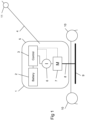
- a lawnmower 1 according to an embodiment of the invention is shown in Figure 1 of the accompanying drawings.
- This lawnmower comprises a housing 5, supported on wheels 10 (although the lawnmower could equally well be a hover mower, which is supported on a cushion of air in use).
- the lawnmower 1 is a battery-powered lawnmower, in that its source of power is an electric battery 2 contained within the housing.
- the battery is used to power an electric motor 7, which drives a rotary blade 9 by means of drive axle 8 coupled to the motor out-put shaft, typically by means of a gearbox (not shown).
- the supply of electric current from the battery 2 to the motor 7 is controlled by a control circuit 3.
- This is arranged so as to be able to control the motor so as to rotate at a given rotational speed over a range of loadings; such control techniques are well known in the art.
- the control circuit 3 will determine the speed of the motor by means of a sensor that is part of the motor 7 and use this to determine how much current to supply to the motor 7.
- the user pushes the lawnmower by means of handle 4.
- the operation (typically on/off) of the lawnmower 1 is controlled by control switch 11, which is connected to the control circuit 3.
- a current sensor 6 is provided between the battery 2 and the motor 7, to monitor the level of current flowing into the motor.
- the output of the current sensor (shown as a dotted line in Figure 1 ) is connected to the control circuit 3.
- control circuit 3 carries out the method shown in Figure 2 of the accompanying drawings. In this method, whenever the user starts up the lawnmower (by activating control switch 11), the control circuit carries out the following checks at step 20:
- control circuit checks whether the results of the above checks are within normal limits; if not, the control circuit 3 proceeds to step 24 and terminates, preventing the starting of the motor.
- the control circuit starts (at step 26) the motor running at a low speed, such that the speed of the blade 9 is kept at approximately 2600 to 2800 revolutions per minute (rpm), depending on the size of the blade (it being desirable for the linear velocity of the tip of the blade to be the same regardless of the size of the blade within the typical range of blade sizes of 30 to 50 centimetre diameter).
- This speed should normally be sufficient for use in light cutting conditions, such as those experienced by a user cutting the same lawn once or twice a week.
- the method enters the loop at decision block 30. This decides whether the speed of the motor 7 is low. On entry the speed generally will be, because that is what the control circuit 3 started with at step 26. As such, the method enters the low speed mode 32.
- the low speed mode starts by waiting (at step 34) a second before changing any status of the motor 7. As such, the control circuit 3 will stay in the low speed mode 32 for at least a second.
- the control circuit then, at step 36, continually checks whether the current is above a first threshold at step 36, using the output of the current sensor 6. If not, then the blade 9 is not under such load as to require extra assistance in cutting, and so the control circuit 3 can remain in the low speed mode, and the method returns to step 36 so as to check the current once again.
- the control circuit at step 38, increase the speed of the motor 7 to a high speed, typically 3000 to 3200 rpm (again, it being desirable for the linear velocity of the tip of the blade to be the same regardless of the size of the blade within the typical range of blade sizes of 30 to 50 centimetre diameter). This speedwill still be less than the maximum speed of the motor if the speed were uncontrolled, but still provides significant extra assistance in grass cutting.
- the low speed mode 32 is exited, and the method returns to decision block 30.
- the speed is now not low, and so the high speed mode 40 is entered.
- the high speed mode first contains a pause, this time of four seconds (step 42); these pauses 34, 42 prevent unnecessarily frequent switching of modes.
- the control circuit then starts to continually monitor (at step 44) the current flowing through the motor 7, using the output of the current sensor 6. If the current stays above a second threshold, which is lower than the first threshold (again to prevent unnecessary cycling between modes) for a predetermined period of time (say four seconds), then the method continues to monitor the current at step 44. If the current does fall below the second threshold, then the load on the blade 9 has lessened, and so the user does not require the boost in assistance any further. As such, the control circuit commences, at step 46, to control the motor 7 so as to run at the low speed once more.
- the high speed mode 40 then exits and returns control to the decision block 30. As the speed of the motor is now low, the low speed mode 32 is once more entered, as discussed above.
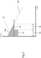
- the motor when the load is low, in range 56, the motor will be run at the low speed 52. Once the load increases into range 58, the motor will be run at the high speed 54. Both of these speeds are lower than the maximum speed 50a of the motor 7 for the given load. As such, the shaded area 56 between the lines 50a, 52 and 54 represents the area where energy is being saved, without any action by the user.
Description
- This invention relates to power tools, such as, non-exclusively, battery-powered lawnmowers.
- Battery operated power tools are now well known in the prior art, and typically comprise an electric battery as a power source, an electric motor controlled by a control circuit of some kind, and a driven element such as a blade or a rotary bit, driven by the motor. They allow the tools to be much more portable than if they were tied to mains electricity by means of a power cord.
- However, with such tools it is important to save energy, to make efficient use of the energy stored within the battery to avoid the need to charge or replace the battery becoming unnecessarily frequent. Of course, energy conservation is advantageous as a general rule. The patent document
EP 2281650 discloses an electric power tool being configured with a transmission assembly with a high speed path and a low speed path. A control unit is also provided for engaging or disengaging the high speed transmission path.WO 2007098227 suggests a power drill configured to change between two sets of motor windings - one for a high-torque mode, and another for an energy-saving mode. Battery powered lawnmowers have been proposed. A traditional rear-collect lawnmower will typically have a blade ofdiameter 30 to 50 centimetres. Energy is absorbed by the grass as it is cut; running the blade at an unnecessarily high speed will result in unnecessarily high energy losses, particularly losses to windage (that is, energy carried in the movement of air). - According to a first aspect of the invention, there is provided a power tool according to
claim 1. - As such, this allows the tool to use a low speed mode when that is all that required; when the current flowing through the motor indicates that strenuous activity is occurring (as the load on the motor increases), then the speed of the motor will be increased. Because the motor is only run at the higher speed when deemed necessary, more efficient use of power is made. Furthermore, the tool will generally run quieter, as the generally noisier high speed mode will only be used when it is necessary. The switch between modes can be automatic and transparent to the user.
- The tool is a battery-operated power tool, where the power source comprises a battery. In such a case, the need to conserver electricity is even more important.
- Typically, the control circuit will be arranged so as to switch to the high speed mode when the current signal indicates increasing current (generally indicating higher load), and to switch to the low speed mode when the current signal indicates lessening current (thus indicating lower load).
- The control circuit may be arranged so as to switch from the low speed mode to the high speed mode when the current signal indicates a current exceeding a first threshold, and possibly also to switch from the high speed mode to the low speed mode when the current signal indicates a current below a second threshold; typically, the first and second thresholds will be different (although they need not be). The first threshold may be higher than the second threshold, so as to avoid the control circuit oscillating quickly between the two modes.
- The control circuit may be arranged so that, when it switches from the high speed mode to the low speed mode or from the low speed mode to the high speed mode, it will not switch back into the other mode for a predetermined period of time, typically at least 1, 2, 3 or 4 seconds; the predetermined period may be different for switching between one pair of modes and the other. The delay prevents, or at least reduces, unnecessarily frequency cycling between modes. Additionally or alternatively, the control circuit may be arranged so that, when determining whether the current signal indicates a current that has crossed at least one of the first or second thresholds, it does not so determine unless the current has crossed the first or second threshold for a period of time, typically 1, 2, 3, or 4 seconds.
- Typically, the tool will be a lawnmower, with the driven element being a grass-cutting blade. In such a case, the first desired speed may be between 2900 to 3300 revolutions per minute (rpm) (typically between 3000 to 3200 rpm) and the second desired speed may be between 2500 to 2900 rpm (typically between 2600 to 2800 rpm).
- However, the tool need not be a lawnmower, and may instead be a hedge trimmer, line trimmer, drill or so on.
- According to a second aspect of the invention, there is provided a method of controlling a power tool according to
claim 7. - As such, this allows the tool to use a low speed mode when that is all that required; when the current flowing through the motor indicates that strenuous activity is occurring (as the load on the motor increases), then the speed of the motor will be increased. Because the motor is only run at the higher speed when deemed necessary, more efficient use of power is made. Furthermore, the tool will generally run quieter, as the generally noisier high speed mode will only be used when it is necessary.
- The tool is a battery-operated power tool, where the power source comprises a battery. In such a case, the need to conserver electricity is even more important.
- Typically, method will comprise switching to the high speed mode when the current increases (generally indicating higher load), and switching to the low speed mode when the current lessens (thus indicating lower load).
- The method may comprise switching from the low speed mode to the high speed mode when the current exceeds a first threshold, and possibly switching from the high speed mode to the low speed mode when the current falls below a second threshold; typically, the first and second thresholds will be different (although they need not be). The first threshold may be higher than the second threshold, so as to avoid the control circuit oscillating quickly between the two modes.
- The method may comprise, after switching from the high speed mode to the low speed mode or from the low speed mode to the high speed mode, not switching back into the other mode for a predetermined period of time, at least 1, 2, 3 or 4 seconds; the predetermined period may be different for switching between one pair of modes and the other. This delay prevents, or at least reduces, unnecessarily frequency cycling between modes.
- Additionally or alternatively, the method may comprise, when determining whether the current signal indicates a current that has crossed at least one of the first or second thresholds, not so determining unless the current has crossed the first or second threshold for a period of time, typically 1, 2, 3, or 4 seconds.
- Typically, the tool will be a lawnmower, with the driven element being a grass-cutting blade. In such a case, the first desired speed may be between 2900 to 3300 revolutions per minute (rpm) (typically between 3000 to 3200 rpm) and the second desired speed may be between 2500 to 2900 rpm (typically between 2600 to 2800 rpm).
- However, the tool need not be a lawnmower, and may instead be a hedge trimmer, line trimmer, drill or so on.
- There now follows, by way of example only, an embodiment of the present invention, described with reference to an as illustrated in the accompanying drawings, in which:
- Figure 1
- shows a schematic view of a lawnmower according to an embodiment of the invention;
- Figure 2
- shows a flowchart showing the operation of the control circuit of the lawnmower of
Figure 1 ; and - Figure 3
- shows a graph of blade speed against blade load.
- A
lawnmower 1 according to an embodiment of the invention is shown inFigure 1 of the accompanying drawings. This lawnmower comprises ahousing 5, supported on wheels 10 (although the lawnmower could equally well be a hover mower, which is supported on a cushion of air in use). Thelawnmower 1 is a battery-powered lawnmower, in that its source of power is anelectric battery 2 contained within the housing. The battery is used to power anelectric motor 7, which drives arotary blade 9 by means of driveaxle 8 coupled to the motor out-put shaft, typically by means of a gearbox (not shown). - The supply of electric current from the
battery 2 to themotor 7 is controlled by acontrol circuit 3. This is arranged so as to be able to control the motor so as to rotate at a given rotational speed over a range of loadings; such control techniques are well known in the art. Typically, thecontrol circuit 3 will determine the speed of the motor by means of a sensor that is part of themotor 7 and use this to determine how much current to supply to themotor 7. - The user pushes the lawnmower by means of
handle 4. The operation (typically on/off) of thelawnmower 1 is controlled bycontrol switch 11, which is connected to thecontrol circuit 3. - A
current sensor 6 is provided between thebattery 2 and themotor 7, to monitor the level of current flowing into the motor. The output of the current sensor (shown as a dotted line inFigure 1 ) is connected to thecontrol circuit 3. - In order to control the lawnmower, the
control circuit 3 carries out the method shown inFigure 2 of the accompanying drawings. In this method, whenever the user starts up the lawnmower (by activating control switch 11), the control circuit carries out the following checks at step 20: - Motor temperature check
- Controller temperature check
- Battery Management Logic output check
- Supply Voltage check (that is, that the
battery 2 has sufficient charge) - Motor hall sensor (magnetic position sensors that can observe the passage of the magnetic poles in the motor's rotor; used to determine the speed of the rotor) check
- At
step 22, the control circuit checks whether the results of the above checks are within normal limits; if not, thecontrol circuit 3 proceeds to step 24 and terminates, preventing the starting of the motor. - If the results of the tests are successful, the control circuit starts (at step 26) the motor running at a low speed, such that the speed of the
blade 9 is kept at approximately 2600 to 2800 revolutions per minute (rpm), depending on the size of the blade (it being desirable for the linear velocity of the tip of the blade to be the same regardless of the size of the blade within the typical range of blade sizes of 30 to 50 centimetre diameter). This speed should normally be sufficient for use in light cutting conditions, such as those experienced by a user cutting the same lawn once or twice a week. - The remainder of the method shown forms a loop, which will run until the user switches off power once again.
- The method enters the loop at
decision block 30. This decides whether the speed of themotor 7 is low. On entry the speed generally will be, because that is what thecontrol circuit 3 started with atstep 26. As such, the method enters thelow speed mode 32. - The low speed mode starts by waiting (at step 34) a second before changing any status of the
motor 7. As such, thecontrol circuit 3 will stay in thelow speed mode 32 for at least a second. The control circuit then, atstep 36, continually checks whether the current is above a first threshold atstep 36, using the output of thecurrent sensor 6. If not, then theblade 9 is not under such load as to require extra assistance in cutting, and so thecontrol circuit 3 can remain in the low speed mode, and the method returns to step 36 so as to check the current once again. - If the current has increased above the first threshold, then the user will likely be cutting grass that has put significant extra load on the blade. Thus, in order to provide extra assistance to the cutting, the control circuit, at step 38, increase the speed of the
motor 7 to a high speed, typically 3000 to 3200 rpm (again, it being desirable for the linear velocity of the tip of the blade to be the same regardless of the size of the blade within the typical range of blade sizes of 30 to 50 centimetre diameter). This speedwill still be less than the maximum speed of the motor if the speed were uncontrolled, but still provides significant extra assistance in grass cutting. - Once the motor has been sped up to the high speed, the
low speed mode 32 is exited, and the method returns todecision block 30. The speed is now not low, and so thehigh speed mode 40 is entered. - As with the
low speed mode 32, the high speed mode first contains a pause, this time of four seconds (step 42); thesepauses - The control circuit then starts to continually monitor (at step 44) the current flowing through the
motor 7, using the output of thecurrent sensor 6. If the current stays above a second threshold, which is lower than the first threshold (again to prevent unnecessary cycling between modes) for a predetermined period of time (say four seconds), then the method continues to monitor the current atstep 44. If the current does fall below the second threshold, then the load on theblade 9 has lessened, and so the user does not require the boost in assistance any further. As such, the control circuit commences, atstep 46, to control themotor 7 so as to run at the low speed once more. - The
high speed mode 40 then exits and returns control to thedecision block 30. As the speed of the motor is now low, thelow speed mode 32 is once more entered, as discussed above. - The effects of the invention as applied in this embodiment can be seen in
Figure 3 of the accompanying drawings, which show a graph of motor speed against load.Straight line segments blade 9 is driven decreases. - However, if the method of this embodiment is employed, then when the load is low, in
range 56, the motor will be run at thelow speed 52. Once the load increases intorange 58, the motor will be run at thehigh speed 54. Both of these speeds are lower than themaximum speed 50a of themotor 7 for the given load. As such, the shadedarea 56 between thelines - Above
range 58, the method of the present embodiment will run themotor 7 at the same speed as the prior art would achieve (50b); there is therefore no energy saving in this area, but no extra energy expenditure.
Claims (12)
- A battery-operated power tool (1), comprising: a driven element (9), an electric motor (7) coupled to the driven element (9) so as to drive the driven element (9), an electric power source (2) electrically coupled to the motor (7) so as to supply electric current to the motor (2), the power source (2) comprising a battery, a control circuit (3) arranged to control the supply of electric current to the motor (7) from the power source (2), and a current sensor (6) operable to out-put a current signal indicative of the current flowing through the motor (7), the power tool being characterized in that the control circuit (3) has a high speed mode and a low speed mode, the control circuit (3) being arranged so that:when it is in the high speed mode, the control circuit (3) supplies electric current to the motor (7) so as to attempt to drive the driven element (9) at a first speed;when it is in the low speed mode, the control circuit (3) supplies electric current to the motor (7) so as to attempt to drive the driven element (9) at a second desired speed which is lower than the first desired speed; andthe control circuit (3) switches between the high speed mode and the low speed mode dependent on the current signal, whereinthe control circuit (3) is arranged to control the motor (7), when in the high speed mode, over a range of loadings of the driven element (9), such that the motor (7) runs at a speed such that the driven element (9) is driven at the first desired speed and, when in the low speed mode, over a range of loadings of the driven element (9), such that the motor (7) runs at a speed such that the driven element (9) is driven at the second desired speed.
- The tool (1) of claim 1, in which the control circuit (3) is arranged so as to switch to the high speed mode when the current signal indicates in-creasing current and to switch to the low speed mode when the current signal indicates lessening current.
- The tool (1) of any preceding claim, in which the control circuit (3) is arranged so as to switch from the low speed mode to the high speed mode when the current signal indicates a current exceeding a first threshold, and to switch from the high speed mode to the low speed mode when the current signal indicates a current below a second threshold.
- The tool (1) of any proceeding claim, in which the control circuit (3) is arranged so that, when it switches from the high speed mode to the low speed mode or from the low speed mode to the high speed mode, it will not switch back into the other mode for a pre-determined period of time.
- The tool (1) of any proceeding claim, being a lawn-mower, with the driven element (9) being a grass-cutting blade.
- The tool (1) of claim 6, in which the first desired speed is between 2900 to 3300 revolutions per minute (rpm) (typically between 3000 to 3200 rpm) and the second desired speed is between 2500 to 2900 rpm (typically between 2600 to 2800 rpm).
- A method of controlling a battery-operated power tool (1), the power tool (1) comprising a driven element (9), an electric motor (7) coupled to the driven element (9) so as to drive the driven element (9), and an electric power source (2) electrically coupled to the motor (7) so as to supply electric current to the motor (2), the electric power source comprising a battery, wherein said method comprises:controlling, by means of a control circuit (3), the supply of electric current to the motor (7) from the power source (2) the method being characterized inthe control circuit (3) driving the electric motor (7) in a high speed mode by supplying electric current to the motor (7) so as to attempt to drive the driven element (9) at a first desired speedand in a low speed mode by supplying electric current to the motor (7) so as to attempt to drive the driven element (9) at a second desired speed which is lower than the first desired speed; andthe control circuit (3) also switching between the high speed mode and the low speed mode dependent of the current flowing through the motor (7), andcomprising controlling the motor (2) to run, when in the high speed mode, over a range of loadings of the driven element (9), at a speed such that the driven element (9) is driven at the first desired speed and, when in the low speed mode, over a range of loading of the driven element (9), at a speed such that the driven element (9) is driven at the second desired speed.
- The method of claim 7, comprising switching to the high speed mode when the current increases and switching to the low speed mode when the current lessens.
- The method of claim 7 or claim 8, comprising switching from the low speed mode to the high speed mode when the current exceeds a first threshold, and switching from the high speed mode to the low speed mode when the current falls below a second threshold.
- The method of any of claims 7 to 9, comprising, after switching from the high speed mode to the low speed mode or from the low speed mode to the high speed mode, not switching back into the other mode for a predetermined period of time.
- The method of any of claims 7 to 10, in which the tool (1) is a lawnmower, with the driven element (9) being a grass-cutting blade.
- The method of claim 11, in which the first desired speed is between 2900 to 3300 revolutions per minute (rpm) (typically between 3000 to 3200 rpm) and the second desired speed is between 2500 to 2900 rpm (typically between 2600 to 2800 rpm).
Applications Claiming Priority (1)
| Application Number | Priority Date | Filing Date | Title |
|---|---|---|---|
| PCT/GB2011/051149 WO2012175901A1 (en) | 2011-06-20 | 2011-06-20 | Speed control for power tools |
Publications (3)
| Publication Number | Publication Date |
|---|---|
| EP2720526A1 EP2720526A1 (en) | 2014-04-23 |
| EP2720526B1 EP2720526B1 (en) | 2019-01-23 |
| EP2720526B2 true EP2720526B2 (en) | 2024-03-20 |
Family
ID=44532940
Family Applications (1)
| Application Number | Title | Priority Date | Filing Date |
|---|---|---|---|
| EP11749480.7A Active EP2720526B2 (en) | 2011-06-20 | 2011-06-20 | Speed control for power tools |
Country Status (3)
| Country | Link |
|---|---|
| US (1) | US9257925B2 (en) |
| EP (1) | EP2720526B2 (en) |
| WO (1) | WO2012175901A1 (en) |
Families Citing this family (34)
| Publication number | Priority date | Publication date | Assignee | Title |
|---|---|---|---|---|
| ES2707155T3 (en) | 2006-03-17 | 2019-04-02 | Irobot Corp | Robot confinement |
| DE202014102422U1 (en) * | 2013-05-31 | 2014-08-08 | Hitachi Koki Co., Ltd. | Electric power tools |
| JP2015024486A (en) * | 2013-07-29 | 2015-02-05 | 日立工機株式会社 | Electric tool |
| AU2015241429B2 (en) | 2014-03-31 | 2018-12-06 | Irobot Corporation | Autonomous mobile robot |
| CN203831362U (en) * | 2014-04-24 | 2014-09-17 | 天佑电器(苏州)有限公司 | Electric tool kit |
| CN103963023A (en) * | 2014-04-24 | 2014-08-06 | 天佑电器(苏州)有限公司 | Combined electric tool and control method thereof |
| US9516806B2 (en) | 2014-10-10 | 2016-12-13 | Irobot Corporation | Robotic lawn mowing boundary determination |
| US9510505B2 (en) | 2014-10-10 | 2016-12-06 | Irobot Corporation | Autonomous robot localization |
| US9420741B2 (en) | 2014-12-15 | 2016-08-23 | Irobot Corporation | Robot lawnmower mapping |
| US9538702B2 (en) | 2014-12-22 | 2017-01-10 | Irobot Corporation | Robotic mowing of separated lawn areas |
| US20160353659A1 (en) * | 2015-06-05 | 2016-12-08 | Mtd Products Inc | High-efficiency lawn maintenance tool |
| US11115798B2 (en) | 2015-07-23 | 2021-09-07 | Irobot Corporation | Pairing a beacon with a mobile robot |
| US10034421B2 (en) | 2015-07-24 | 2018-07-31 | Irobot Corporation | Controlling robotic lawnmowers |
| CN106416588B (en) * | 2015-08-05 | 2019-08-02 | 南京德朔实业有限公司 | Grass trimmer and control method thereof |
| DE102015217053A1 (en) * | 2015-09-07 | 2017-03-09 | Robert Bosch Gmbh | Hand tool |
| CN106576569B (en) * | 2015-10-14 | 2020-01-31 | 南京德朔实业有限公司 | Electric tool and control method thereof |
| EP3400109A4 (en) | 2016-01-05 | 2019-10-16 | Milwaukee Electric Tool Corporation | Vibration reduction system and method for power tools |
| US10021830B2 (en) | 2016-02-02 | 2018-07-17 | Irobot Corporation | Blade assembly for a grass cutting mobile robot |
| CN108778651B (en) | 2016-02-03 | 2021-06-18 | 米沃奇电动工具公司 | System and method for configuring a reciprocating saw |
| US10459063B2 (en) | 2016-02-16 | 2019-10-29 | Irobot Corporation | Ranging and angle of arrival antenna system for a mobile robot |
| WO2019013989A1 (en) | 2017-07-14 | 2019-01-17 | Irobot Corporation | Blade assembly for a grass cutting mobile robot |
| IT201700087949A1 (en) * | 2017-07-31 | 2019-01-31 | Stiga S P A In Breve Anche St S P A | Mower with tilt sensor to inhibit starting |
| JP6901346B2 (en) * | 2017-08-09 | 2021-07-14 | 株式会社マキタ | Electric work machine |
| EP3711471B1 (en) * | 2017-11-17 | 2021-12-08 | Honda Motor Co., Ltd. | Work machine |
| US11338405B2 (en) | 2018-02-28 | 2022-05-24 | Milwaukee Electric Tool Corporation | Eco-indicator for power tool |
| CN111788053A (en) | 2018-02-28 | 2020-10-16 | 米沃奇电动工具公司 | Simulated stagnation systems and methods for power tools |
| CN213646135U (en) | 2018-03-16 | 2021-07-09 | 米沃奇电动工具公司 | Blade clamp and reciprocating electric tool |
| USD887806S1 (en) | 2018-04-03 | 2020-06-23 | Milwaukee Electric Tool Corporation | Jigsaw |
| EP3774148A4 (en) | 2018-04-03 | 2021-12-15 | Milwaukee Electric Tool Corporation | Jigsaw |
| JP6641607B2 (en) * | 2018-12-28 | 2020-02-05 | 工機ホールディングス株式会社 | Electric tool |
| JP2020145986A (en) * | 2019-03-14 | 2020-09-17 | 株式会社丸山製作所 | Bush cutter |
| JP6885455B2 (en) * | 2019-12-27 | 2021-06-16 | 工機ホールディングス株式会社 | Electric tool |
| US11919135B2 (en) | 2020-07-06 | 2024-03-05 | Milwaukee Electric Tool Corporation | Automatic ramp load sense for power tools |
| EP4263138A1 (en) | 2020-12-18 | 2023-10-25 | Black & Decker Inc. | Impact tools and control modes |
Citations (3)
| Publication number | Priority date | Publication date | Assignee | Title |
|---|---|---|---|---|
| DE3214482A1 (en) † | 1982-04-20 | 1983-11-03 | Kress-elektrik GmbH & Co, Elektromotorenfabrik, 7457 Bisingen | Circuit arrangement for speed control of a hand-held machine tool |
| DE19809988A1 (en) † | 1998-03-09 | 1999-10-07 | Gardena Kress & Kastner Gmbh | Hand-held work tool driven by an electric motor |
| DE102007015991A1 (en) † | 2006-04-21 | 2007-10-25 | Andreas Stihl Ag & Co. Kg | Weed whacker, has control unit operating electrical drive motor in idle operation after one of operating curves and in loading condition after another operating curve, where operating curves are assigned to control unit |
Family Cites Families (7)
| Publication number | Priority date | Publication date | Assignee | Title |
|---|---|---|---|---|
| US5937622A (en) | 1995-07-26 | 1999-08-17 | Black & Decker Inc. | Cordless electric lawn mower having energy management control system |
| US7602137B2 (en) * | 2006-02-20 | 2009-10-13 | Black & Decker Inc. | Electronically commutated motor and control system |
| US7479754B2 (en) * | 2006-10-17 | 2009-01-20 | Desa Ip Llc | Hybrid electric lawnmower |
| CN101247100B (en) | 2007-02-16 | 2012-01-25 | 苏州宝时得电动工具有限公司 | Electric tool control method and electric tool using the same |
| EP2030709A3 (en) * | 2007-08-29 | 2013-01-16 | Positec Power Tools (Suzhou) Co., Ltd. | Power tool |
| JP5112956B2 (en) * | 2008-05-30 | 2013-01-09 | 株式会社マキタ | Rechargeable power tool |
| US8172004B2 (en) | 2009-08-05 | 2012-05-08 | Techtronic Power Tools Technology Limited | Automatic transmission for a power tool |
-
2011
- 2011-06-20 US US14/125,225 patent/US9257925B2/en active Active
- 2011-06-20 EP EP11749480.7A patent/EP2720526B2/en active Active
- 2011-06-20 WO PCT/GB2011/051149 patent/WO2012175901A1/en active Application Filing
Patent Citations (3)
| Publication number | Priority date | Publication date | Assignee | Title |
|---|---|---|---|---|
| DE3214482A1 (en) † | 1982-04-20 | 1983-11-03 | Kress-elektrik GmbH & Co, Elektromotorenfabrik, 7457 Bisingen | Circuit arrangement for speed control of a hand-held machine tool |
| DE19809988A1 (en) † | 1998-03-09 | 1999-10-07 | Gardena Kress & Kastner Gmbh | Hand-held work tool driven by an electric motor |
| DE102007015991A1 (en) † | 2006-04-21 | 2007-10-25 | Andreas Stihl Ag & Co. Kg | Weed whacker, has control unit operating electrical drive motor in idle operation after one of operating curves and in loading condition after another operating curve, where operating curves are assigned to control unit |
Also Published As
| Publication number | Publication date |
|---|---|
| EP2720526B1 (en) | 2019-01-23 |
| WO2012175901A1 (en) | 2012-12-27 |
| US20140117892A1 (en) | 2014-05-01 |
| US9257925B2 (en) | 2016-02-09 |
| EP2720526A1 (en) | 2014-04-23 |
Similar Documents
| Publication | Publication Date | Title |
|---|---|---|
| EP2720526B2 (en) | Speed control for power tools | |
| EP2835045B1 (en) | Vegetation cutting device | |
| US7741793B2 (en) | Hybrid electric device | |
| US7728534B2 (en) | Hybrid electric lawnmower | |
| US9787225B2 (en) | Hybrid electric device | |
| US7886509B2 (en) | Load-responsive energy-saving motor-driven grass mower | |
| CN103660997B (en) | Electric lawn tractor power management system and method | |
| KR101160478B1 (en) | A motor-driven grass mower | |
| US20140165525A1 (en) | Motor drive device and electric mowing machine | |
| EP3155887B1 (en) | Power tool and control method thereof | |
| US20080086997A1 (en) | Hybrid electric device | |
| US11700787B2 (en) | Electric walk behind greens mower | |
| GB2303719A (en) | Control device for an electric motor | |
| KR20180096774A (en) | Electric lawn mower with automatic blade clogging function and control method of such lawn mower | |
| CN103518487A (en) | Hay mower driven by double battery packs | |
| US20190344419A1 (en) | Power Device, Electric Power Tool, and System | |
| EP2027768B1 (en) | Cutting apparatus | |
| CN107771510B (en) | Locked-rotor control method of intelligent mower and intelligent mower | |
| CN203575118U (en) | Dual battery pack driven mowing machine | |
| CN201110271Y (en) | DC brushless evaporation fan for bus air conditioner non position sensor | |
| CN115173624A (en) | Direct-current brushless motor with starting protection function for mower | |
| CN201563384U (en) | Plant cover trimming machine | |
| JP2020068703A (en) | Lawn mower | |
| CN115843529A (en) | Heat dissipation control method of electric grass trimmer | |
| JP2012157269A (en) | Drive control device of electric husbandry machine |
Legal Events
| Date | Code | Title | Description |
|---|---|---|---|
| PUAI | Public reference made under article 153(3) epc to a published international application that has entered the european phase |
Free format text: ORIGINAL CODE: 0009012 |
|
| 17P | Request for examination filed |
Effective date: 20140120 |
|
| AK | Designated contracting states |
Kind code of ref document: A1 Designated state(s): AL AT BE BG CH CY CZ DE DK EE ES FI FR GB GR HR HU IE IS IT LI LT LU LV MC MK MT NL NO PL PT RO RS SE SI SK SM TR |
|
| RAP1 | Party data changed (applicant data changed or rights of an application transferred) |
Owner name: HUSQVARNA AB |
|
| DAX | Request for extension of the european patent (deleted) | ||
| STAA | Information on the status of an ep patent application or granted ep patent |
Free format text: STATUS: EXAMINATION IS IN PROGRESS |
|
| 17Q | First examination report despatched |
Effective date: 20170905 |
|
| REG | Reference to a national code |
Ref country code: DE Ref legal event code: R079 Ref document number: 602011055909 Country of ref document: DE Free format text: PREVIOUS MAIN CLASS: A01D0034000000 Ipc: B25F0005000000 |
|
| RIC1 | Information provided on ipc code assigned before grant |
Ipc: B25F 5/00 20060101AFI20180627BHEP Ipc: H02P 7/06 20060101ALI20180627BHEP Ipc: A01D 34/00 20060101ALI20180627BHEP Ipc: A01D 69/02 20060101ALI20180627BHEP |
|
| GRAP | Despatch of communication of intention to grant a patent |
Free format text: ORIGINAL CODE: EPIDOSNIGR1 |
|
| STAA | Information on the status of an ep patent application or granted ep patent |
Free format text: STATUS: GRANT OF PATENT IS INTENDED |
|
| INTG | Intention to grant announced |
Effective date: 20180815 |
|
| GRAS | Grant fee paid |
Free format text: ORIGINAL CODE: EPIDOSNIGR3 |
|
| GRAA | (expected) grant |
Free format text: ORIGINAL CODE: 0009210 |
|
| STAA | Information on the status of an ep patent application or granted ep patent |
Free format text: STATUS: THE PATENT HAS BEEN GRANTED |
|
| AK | Designated contracting states |
Kind code of ref document: B1 Designated state(s): AL AT BE BG CH CY CZ DE DK EE ES FI FR GB GR HR HU IE IS IT LI LT LU LV MC MK MT NL NO PL PT RO RS SE SI SK SM TR |
|
| REG | Reference to a national code |
Ref country code: GB Ref legal event code: FG4D |
|
| REG | Reference to a national code |
Ref country code: CH Ref legal event code: EP |
|
| REG | Reference to a national code |
Ref country code: AT Ref legal event code: REF Ref document number: 1091084 Country of ref document: AT Kind code of ref document: T Effective date: 20190215 |
|
| REG | Reference to a national code |
Ref country code: IE Ref legal event code: FG4D |
|
| REG | Reference to a national code |
Ref country code: DE Ref legal event code: R096 Ref document number: 602011055909 Country of ref document: DE |
|
| REG | Reference to a national code |
Ref country code: NL Ref legal event code: MP Effective date: 20190123 |
|
| PG25 | Lapsed in a contracting state [announced via postgrant information from national office to epo] |
Ref country code: NL Free format text: LAPSE BECAUSE OF FAILURE TO SUBMIT A TRANSLATION OF THE DESCRIPTION OR TO PAY THE FEE WITHIN THE PRESCRIBED TIME-LIMIT Effective date: 20190123 |
|
| PG25 | Lapsed in a contracting state [announced via postgrant information from national office to epo] |
Ref country code: PL Free format text: LAPSE BECAUSE OF FAILURE TO SUBMIT A TRANSLATION OF THE DESCRIPTION OR TO PAY THE FEE WITHIN THE PRESCRIBED TIME-LIMIT Effective date: 20190123 Ref country code: FI Free format text: LAPSE BECAUSE OF FAILURE TO SUBMIT A TRANSLATION OF THE DESCRIPTION OR TO PAY THE FEE WITHIN THE PRESCRIBED TIME-LIMIT Effective date: 20190123 Ref country code: LT Free format text: LAPSE BECAUSE OF FAILURE TO SUBMIT A TRANSLATION OF THE DESCRIPTION OR TO PAY THE FEE WITHIN THE PRESCRIBED TIME-LIMIT Effective date: 20190123 Ref country code: ES Free format text: LAPSE BECAUSE OF FAILURE TO SUBMIT A TRANSLATION OF THE DESCRIPTION OR TO PAY THE FEE WITHIN THE PRESCRIBED TIME-LIMIT Effective date: 20190123 Ref country code: SE Free format text: LAPSE BECAUSE OF FAILURE TO SUBMIT A TRANSLATION OF THE DESCRIPTION OR TO PAY THE FEE WITHIN THE PRESCRIBED TIME-LIMIT Effective date: 20190123 Ref country code: NO Free format text: LAPSE BECAUSE OF FAILURE TO SUBMIT A TRANSLATION OF THE DESCRIPTION OR TO PAY THE FEE WITHIN THE PRESCRIBED TIME-LIMIT Effective date: 20190423 Ref country code: PT Free format text: LAPSE BECAUSE OF FAILURE TO SUBMIT A TRANSLATION OF THE DESCRIPTION OR TO PAY THE FEE WITHIN THE PRESCRIBED TIME-LIMIT Effective date: 20190523 |
|
| REG | Reference to a national code |
Ref country code: AT Ref legal event code: MK05 Ref document number: 1091084 Country of ref document: AT Kind code of ref document: T Effective date: 20190123 |
|
| PG25 | Lapsed in a contracting state [announced via postgrant information from national office to epo] |
Ref country code: IS Free format text: LAPSE BECAUSE OF FAILURE TO SUBMIT A TRANSLATION OF THE DESCRIPTION OR TO PAY THE FEE WITHIN THE PRESCRIBED TIME-LIMIT Effective date: 20190523 Ref country code: HR Free format text: LAPSE BECAUSE OF FAILURE TO SUBMIT A TRANSLATION OF THE DESCRIPTION OR TO PAY THE FEE WITHIN THE PRESCRIBED TIME-LIMIT Effective date: 20190123 Ref country code: LV Free format text: LAPSE BECAUSE OF FAILURE TO SUBMIT A TRANSLATION OF THE DESCRIPTION OR TO PAY THE FEE WITHIN THE PRESCRIBED TIME-LIMIT Effective date: 20190123 Ref country code: GR Free format text: LAPSE BECAUSE OF FAILURE TO SUBMIT A TRANSLATION OF THE DESCRIPTION OR TO PAY THE FEE WITHIN THE PRESCRIBED TIME-LIMIT Effective date: 20190424 Ref country code: BG Free format text: LAPSE BECAUSE OF FAILURE TO SUBMIT A TRANSLATION OF THE DESCRIPTION OR TO PAY THE FEE WITHIN THE PRESCRIBED TIME-LIMIT Effective date: 20190423 Ref country code: RS Free format text: LAPSE BECAUSE OF FAILURE TO SUBMIT A TRANSLATION OF THE DESCRIPTION OR TO PAY THE FEE WITHIN THE PRESCRIBED TIME-LIMIT Effective date: 20190123 |
|
| REG | Reference to a national code |
Ref country code: DE Ref legal event code: R026 Ref document number: 602011055909 Country of ref document: DE |
|
| PLBI | Opposition filed |
Free format text: ORIGINAL CODE: 0009260 |
|
| PG25 | Lapsed in a contracting state [announced via postgrant information from national office to epo] |
Ref country code: AL Free format text: LAPSE BECAUSE OF FAILURE TO SUBMIT A TRANSLATION OF THE DESCRIPTION OR TO PAY THE FEE WITHIN THE PRESCRIBED TIME-LIMIT Effective date: 20190123 Ref country code: CZ Free format text: LAPSE BECAUSE OF FAILURE TO SUBMIT A TRANSLATION OF THE DESCRIPTION OR TO PAY THE FEE WITHIN THE PRESCRIBED TIME-LIMIT Effective date: 20190123 Ref country code: SK Free format text: LAPSE BECAUSE OF FAILURE TO SUBMIT A TRANSLATION OF THE DESCRIPTION OR TO PAY THE FEE WITHIN THE PRESCRIBED TIME-LIMIT Effective date: 20190123 Ref country code: RO Free format text: LAPSE BECAUSE OF FAILURE TO SUBMIT A TRANSLATION OF THE DESCRIPTION OR TO PAY THE FEE WITHIN THE PRESCRIBED TIME-LIMIT Effective date: 20190123 Ref country code: IT Free format text: LAPSE BECAUSE OF FAILURE TO SUBMIT A TRANSLATION OF THE DESCRIPTION OR TO PAY THE FEE WITHIN THE PRESCRIBED TIME-LIMIT Effective date: 20190123 Ref country code: EE Free format text: LAPSE BECAUSE OF FAILURE TO SUBMIT A TRANSLATION OF THE DESCRIPTION OR TO PAY THE FEE WITHIN THE PRESCRIBED TIME-LIMIT Effective date: 20190123 Ref country code: DK Free format text: LAPSE BECAUSE OF FAILURE TO SUBMIT A TRANSLATION OF THE DESCRIPTION OR TO PAY THE FEE WITHIN THE PRESCRIBED TIME-LIMIT Effective date: 20190123 |
|
| PLAX | Notice of opposition and request to file observation + time limit sent |
Free format text: ORIGINAL CODE: EPIDOSNOBS2 |
|
| 26 | Opposition filed |
Opponent name: ANDREAS STIHL AG & CO. KG Effective date: 20191022 |
|
| PG25 | Lapsed in a contracting state [announced via postgrant information from national office to epo] |
Ref country code: SM Free format text: LAPSE BECAUSE OF FAILURE TO SUBMIT A TRANSLATION OF THE DESCRIPTION OR TO PAY THE FEE WITHIN THE PRESCRIBED TIME-LIMIT Effective date: 20190123 |
|
| PG25 | Lapsed in a contracting state [announced via postgrant information from national office to epo] |
Ref country code: AT Free format text: LAPSE BECAUSE OF FAILURE TO SUBMIT A TRANSLATION OF THE DESCRIPTION OR TO PAY THE FEE WITHIN THE PRESCRIBED TIME-LIMIT Effective date: 20190123 |
|
| PG25 | Lapsed in a contracting state [announced via postgrant information from national office to epo] |
Ref country code: MC Free format text: LAPSE BECAUSE OF FAILURE TO SUBMIT A TRANSLATION OF THE DESCRIPTION OR TO PAY THE FEE WITHIN THE PRESCRIBED TIME-LIMIT Effective date: 20190123 |
|
| REG | Reference to a national code |
Ref country code: CH Ref legal event code: PL |
|
| GBPC | Gb: european patent ceased through non-payment of renewal fee |
Effective date: 20190620 |
|
| PG25 | Lapsed in a contracting state [announced via postgrant information from national office to epo] |
Ref country code: SI Free format text: LAPSE BECAUSE OF FAILURE TO SUBMIT A TRANSLATION OF THE DESCRIPTION OR TO PAY THE FEE WITHIN THE PRESCRIBED TIME-LIMIT Effective date: 20190123 |
|
| PLBB | Reply of patent proprietor to notice(s) of opposition received |
Free format text: ORIGINAL CODE: EPIDOSNOBS3 |
|
| REG | Reference to a national code |
Ref country code: BE Ref legal event code: MM Effective date: 20190630 |
|
| PG25 | Lapsed in a contracting state [announced via postgrant information from national office to epo] |
Ref country code: TR Free format text: LAPSE BECAUSE OF FAILURE TO SUBMIT A TRANSLATION OF THE DESCRIPTION OR TO PAY THE FEE WITHIN THE PRESCRIBED TIME-LIMIT Effective date: 20190123 |
|
| PG25 | Lapsed in a contracting state [announced via postgrant information from national office to epo] |
Ref country code: IE Free format text: LAPSE BECAUSE OF NON-PAYMENT OF DUE FEES Effective date: 20190620 Ref country code: GB Free format text: LAPSE BECAUSE OF NON-PAYMENT OF DUE FEES Effective date: 20190620 |
|
| PG25 | Lapsed in a contracting state [announced via postgrant information from national office to epo] |
Ref country code: BE Free format text: LAPSE BECAUSE OF NON-PAYMENT OF DUE FEES Effective date: 20190630 Ref country code: CH Free format text: LAPSE BECAUSE OF NON-PAYMENT OF DUE FEES Effective date: 20190630 Ref country code: LI Free format text: LAPSE BECAUSE OF NON-PAYMENT OF DUE FEES Effective date: 20190630 Ref country code: LU Free format text: LAPSE BECAUSE OF NON-PAYMENT OF DUE FEES Effective date: 20190620 |
|
| PG25 | Lapsed in a contracting state [announced via postgrant information from national office to epo] |
Ref country code: CY Free format text: LAPSE BECAUSE OF FAILURE TO SUBMIT A TRANSLATION OF THE DESCRIPTION OR TO PAY THE FEE WITHIN THE PRESCRIBED TIME-LIMIT Effective date: 20190123 |
|
| RDAF | Communication despatched that patent is revoked |
Free format text: ORIGINAL CODE: EPIDOSNREV1 |
|
| PG25 | Lapsed in a contracting state [announced via postgrant information from national office to epo] |
Ref country code: MT Free format text: LAPSE BECAUSE OF FAILURE TO SUBMIT A TRANSLATION OF THE DESCRIPTION OR TO PAY THE FEE WITHIN THE PRESCRIBED TIME-LIMIT Effective date: 20190123 Ref country code: HU Free format text: LAPSE BECAUSE OF FAILURE TO SUBMIT A TRANSLATION OF THE DESCRIPTION OR TO PAY THE FEE WITHIN THE PRESCRIBED TIME-LIMIT; INVALID AB INITIO Effective date: 20110620 |
|
| APAH | Appeal reference modified |
Free format text: ORIGINAL CODE: EPIDOSCREFNO |
|
| APBM | Appeal reference recorded |
Free format text: ORIGINAL CODE: EPIDOSNREFNO |
|
| APBP | Date of receipt of notice of appeal recorded |
Free format text: ORIGINAL CODE: EPIDOSNNOA2O |
|
| APBQ | Date of receipt of statement of grounds of appeal recorded |
Free format text: ORIGINAL CODE: EPIDOSNNOA3O |
|
| PG25 | Lapsed in a contracting state [announced via postgrant information from national office to epo] |
Ref country code: MK Free format text: LAPSE BECAUSE OF FAILURE TO SUBMIT A TRANSLATION OF THE DESCRIPTION OR TO PAY THE FEE WITHIN THE PRESCRIBED TIME-LIMIT Effective date: 20190123 |
|
| APAH | Appeal reference modified |
Free format text: ORIGINAL CODE: EPIDOSCREFNO |
|
| P01 | Opt-out of the competence of the unified patent court (upc) registered |
Effective date: 20230419 |
|
| PGFP | Annual fee paid to national office [announced via postgrant information from national office to epo] |
Ref country code: FR Payment date: 20230522 Year of fee payment: 13 Ref country code: DE Payment date: 20230508 Year of fee payment: 13 |
|
| APBU | Appeal procedure closed |
Free format text: ORIGINAL CODE: EPIDOSNNOA9O |
|
| RDAE | Information deleted related to despatch of communication that patent is revoked |
Free format text: ORIGINAL CODE: EPIDOSDREV1 |
|
| PUAH | Patent maintained in amended form |
Free format text: ORIGINAL CODE: 0009272 |
|
| STAA | Information on the status of an ep patent application or granted ep patent |
Free format text: STATUS: PATENT MAINTAINED AS AMENDED |
|
| 27A | Patent maintained in amended form |
Effective date: 20240320 |
|
| AK | Designated contracting states |
Kind code of ref document: B2 Designated state(s): AL AT BE BG CH CY CZ DE DK EE ES FI FR GB GR HR HU IE IS IT LI LT LU LV MC MK MT NL NO PL PT RO RS SE SI SK SM TR |
|
| REG | Reference to a national code |
Ref country code: DE Ref legal event code: R102 Ref document number: 602011055909 Country of ref document: DE |