CN108778651B - System and method for configuring a reciprocating saw - Google Patents
System and method for configuring a reciprocating saw Download PDFInfo
- Publication number
- CN108778651B CN108778651B CN201780009905.7A CN201780009905A CN108778651B CN 108778651 B CN108778651 B CN 108778651B CN 201780009905 A CN201780009905 A CN 201780009905A CN 108778651 B CN108778651 B CN 108778651B
- Authority
- CN
- China
- Prior art keywords
- motor
- power tool
- speed
- cut
- electronic processor
- Prior art date
- Legal status (The legal status is an assumption and is not a legal conclusion. Google has not performed a legal analysis and makes no representation as to the accuracy of the status listed.)
- Active
Links
Images


Classifications
-
- B—PERFORMING OPERATIONS; TRANSPORTING
- B23—MACHINE TOOLS; METAL-WORKING NOT OTHERWISE PROVIDED FOR
- B23D—PLANING; SLOTTING; SHEARING; BROACHING; SAWING; FILING; SCRAPING; LIKE OPERATIONS FOR WORKING METAL BY REMOVING MATERIAL, NOT OTHERWISE PROVIDED FOR
- B23D51/00—Sawing machines or sawing devices working with straight blades, characterised only by constructional features of particular parts; Carrying or attaching means for tools, covered by this subclass, which are connected to a carrier at both ends
- B23D51/16—Sawing machines or sawing devices working with straight blades, characterised only by constructional features of particular parts; Carrying or attaching means for tools, covered by this subclass, which are connected to a carrier at both ends of drives or feed mechanisms for straight tools, e.g. saw blades, or bows
-
- B—PERFORMING OPERATIONS; TRANSPORTING
- B27—WORKING OR PRESERVING WOOD OR SIMILAR MATERIAL; NAILING OR STAPLING MACHINES IN GENERAL
- B27B—SAWS FOR WOOD OR SIMILAR MATERIAL; COMPONENTS OR ACCESSORIES THEREFOR
- B27B17/00—Chain saws; Equipment therefor
- B27B17/0016—Devices to adapt the chain saw for other purposes, e.g. drilling
-
- B—PERFORMING OPERATIONS; TRANSPORTING
- B23—MACHINE TOOLS; METAL-WORKING NOT OTHERWISE PROVIDED FOR
- B23D—PLANING; SLOTTING; SHEARING; BROACHING; SAWING; FILING; SCRAPING; LIKE OPERATIONS FOR WORKING METAL BY REMOVING MATERIAL, NOT OTHERWISE PROVIDED FOR
- B23D59/00—Accessories specially designed for sawing machines or sawing devices
- B23D59/001—Measuring or control devices, e.g. for automatic control of work feed pressure on band saw blade
-
- B—PERFORMING OPERATIONS; TRANSPORTING
- B25—HAND TOOLS; PORTABLE POWER-DRIVEN TOOLS; MANIPULATORS
- B25F—COMBINATION OR MULTI-PURPOSE TOOLS NOT OTHERWISE PROVIDED FOR; DETAILS OR COMPONENTS OF PORTABLE POWER-DRIVEN TOOLS NOT PARTICULARLY RELATED TO THE OPERATIONS PERFORMED AND NOT OTHERWISE PROVIDED FOR
- B25F5/00—Details or components of portable power-driven tools not particularly related to the operations performed and not otherwise provided for
-
- B—PERFORMING OPERATIONS; TRANSPORTING
- B27—WORKING OR PRESERVING WOOD OR SIMILAR MATERIAL; NAILING OR STAPLING MACHINES IN GENERAL
- B27B—SAWS FOR WOOD OR SIMILAR MATERIAL; COMPONENTS OR ACCESSORIES THEREFOR
- B27B17/00—Chain saws; Equipment therefor
- B27B17/08—Drives or gearings; Devices for swivelling or tilting the chain saw
-
- B—PERFORMING OPERATIONS; TRANSPORTING
- B27—WORKING OR PRESERVING WOOD OR SIMILAR MATERIAL; NAILING OR STAPLING MACHINES IN GENERAL
- B27B—SAWS FOR WOOD OR SIMILAR MATERIAL; COMPONENTS OR ACCESSORIES THEREFOR
- B27B33/00—Sawing tools for saw mills, sawing machines, or sawing devices
- B27B33/14—Saw chains
- B27B33/141—Saw chains with means to control the depth of cut
-
- G—PHYSICS
- G08—SIGNALLING
- G08C—TRANSMISSION SYSTEMS FOR MEASURED VALUES, CONTROL OR SIMILAR SIGNALS
- G08C17/00—Arrangements for transmitting signals characterised by the use of a wireless electrical link
- G08C17/02—Arrangements for transmitting signals characterised by the use of a wireless electrical link using a radio link
Abstract
Systems and methods for configuring a power tool. A system includes a power tool communication system including an external device and a power tool. The external device includes a user interface configured to receive a first selection to enable a feature of the power tool and to receive a second selection of a threshold value of a motor characteristic of the power tool. The power tool includes a motor within a housing. The power tool receives the selected feature and the selected threshold from the external device. The power tool includes a sensor configured to monitor a motor characteristic of the motor. The power tool also includes an electronic processor that controls the motor to operate according to the selected characteristic and adjusts an operating parameter of the motor upon determining that the motor characteristic exceeds a selected threshold.
Description
Cross Reference to Related Applications
This patent application claims priority to U.S. provisional patent application No. 62/290,808, filed 2016, 2, 3, the entire contents of which are incorporated herein by reference.
Technical Field
The present invention relates to a power tool that communicates with an external device.
Background
Power tools are known to include a motor that actuates a drive device and allows the drive device to perform a particular task, a primary power source (e.g., a battery pack) is coupled to the power tool and provides power to energize the motor. The motor is energized based on the position of the trigger. The motor is energized when the trigger is depressed, and is de-energized when the trigger is released.
Disclosure of Invention
In one embodiment, a power tool is provided that includes a housing. The power tool includes a motor within a housing, the motor including a rotor and a stator. The power tool also includes a transmission coupled between the motor and the reciprocating spindle. The transmission device converts the rotary motion of the motor into the reciprocating motion of the reciprocating main shaft. The power tool also includes a tool post coupled to the reciprocating spindle, and a sensor configured to monitor the motor current. The power tool also includes an electronic processor coupled to the sensor. The electronic processor initiates driving of the motor in response to determining that the trigger has been depressed. The electronic processor also determines whether the article is cut based on the motor current and whether the article is no longer cut based on the motor current. The electronic processor stops driving the motor in response to determining that the article is no longer being cut.
In another embodiment, there is provided a power tool including: a housing. A motor within the housing, the motor including a rotor and a stator. The power tool also includes a transmission coupled between the motor and the reciprocating spindle. The transmission device converts the rotary motion of the motor into the reciprocating motion of the reciprocating main shaft. The power tool also includes a tool post coupled to the reciprocating spindle, and a sensor configured to monitor the motor current. The power tool also includes an electronic processor coupled to the sensor. The electronic processor initiates driving of the motor in response to determining that the trigger has been depressed. The electronic processor also determines whether the first material is cut based on the motor current. The electronic processor determines a motor current acceleration based on the motor current when the first material is cut. The electronic processor also determines whether the second material is cut based on the motor current acceleration. Stopping driving the motor in response to determining that the second material is cut.
In one embodiment, a power tool communication system is provided that includes an external device and a power tool. The external device includes: a user interface configured to: the method includes receiving a first selection of a type of material to be cut, receiving a second selection of a thickness of the material to be cut, receiving a third selection of a blade type for a blade to cut the material. The external device further includes a first electronic processor configured to control the user interface to display a recommended motor speed based on at least one of the group consisting of: the type of blade selected, the type of material selected, and the thickness of the material selected. The electric tool includes: a housing, and a motor within the housing. The motor includes a rotor and a stator. The power tool further includes a transmission coupled between the motor and the reciprocating spindle. The transmission device converts the rotary motion of the motor into the reciprocating motion of the reciprocating main shaft. The power tool also includes a tool post coupled to the reciprocating spindle. The power tool also includes a wireless communication controller that receives a recommended motor speed from an external device. The power tool also includes a second electronic processor coupled to the wireless communication controller. The second electronic processor controls the motor to operate at the recommended motor speed.
In another embodiment, a power tool communication system is provided, comprising: an external device and a power tool. The external device includes: a user interface configured to: a first selection of a first speed of a motor of the power tool is received, and a second selection of a second speed of the motor of the power tool is received. The user interface is also configured to receive a third selection of a characteristic to be monitored to adjust the speed of the motor from the first speed to the second speed, and receive a fourth selection of a threshold value of the selected characteristic to be monitored. The electric tool includes: a housing, a motor within the housing. The motor includes a rotor and a stator. The power tool further includes a transmission coupled between the motor and the reciprocating spindle. The transmission device converts the rotary motion of the motor into the reciprocating motion of the reciprocating main shaft. The power tool also includes a tool holder coupled to the reciprocating spindle. The power tool also includes a wireless communication controller that receives the selected first speed, the selected second speed, the selected feature to be monitored, and the selected threshold from an external device. The power tool further includes a sensor configured to monitor the selected characteristic; and an electronic processor coupled to the sensor and the wireless communication controller. An electronic processor: in response to determining that the trigger has been depressed, starting to drive the motor, the motor speed is set to a first speed. The electronic processor also determines whether the selected characteristic has exceeded a selected threshold, and increases the motor speed from a first speed to a second speed in response to determining that the selected characteristic has exceeded the selected threshold.
In one embodiment, a method of configuring a power tool is provided. The method includes initiating driving of the motor by the electronic processor in response to determining that the trigger has been depressed. The motor includes a rotor and a stator, and is located within a housing of the power tool. The motor is coupled to a transmission that is coupled to the reciprocating main shaft and converts the rotational motion of the motor into reciprocating motion of the reciprocating main shaft. The reciprocating spindle is coupled to the tool holder. The method also includes monitoring the motor current with a sensor coupled to the electronic processor. The method also includes determining, with the electronic processor, whether the article is cut based on the motor current. The method also includes determining, with the electronic processor, whether the article is no longer cut based on the motor current. The method also includes stopping the drive motor with the electronic processor in response to determining that the article is no longer being cut.
In another embodiment, a method of configuring a power tool is provided. The method includes initiating driving of the motor with the electronic processor in response to determining that the trigger has been depressed. The motor includes a rotor and a stator, and is located within a housing of the power tool. The motor is coupled to a transmission that is coupled to the reciprocating main shaft and converts the rotational motion of the motor into reciprocating motion of the reciprocating main shaft. The reciprocating spindle is coupled to the tool holder. The method also includes monitoring the motor current with a sensor coupled to the electronic processor. The method also includes determining, with the electronic processor, whether the first material is cut based on the motor current. The method also includes determining, with the electronic processor, a motor current acceleration based on the motor current as the first material is cut. The method also includes determining, with the electronic processor, whether the second material is cut based on the motor current acceleration. The method also includes stopping the drive motor with the electronic processor in response to determining that the second material is cut.
In another embodiment, a method of configuring a power tool is provided. The method includes receiving, via a user interface of an external device, a first selection of a type of material to be cut. The method also includes receiving, via a user interface of an external device, a second selection of a thickness of the material to be cut. The method also includes receiving, via a user interface of an external device, a third selection of a blade type of a blade for cutting the material. The method also includes determining, with the first electronic processor of the external device, a recommended motor speed based on at least one of the group consisting of the selected blade type, the selected material type, and the thickness of the selected material. The method also includes displaying the recommended motor speed with a user interface of an external device. The method also includes receiving, with a wireless communication controller of a power tool, a recommended motor speed from an external device, the power tool including a motor. The motor includes a rotor and a stator, and is located within a housing of the power tool. The motor is coupled to a transmission that is coupled to the reciprocating main shaft and converts the rotational motion of the motor into reciprocating motion of the reciprocating main shaft. The reciprocating spindle is coupled to the tool holder. The method also includes controlling, with a second electronic processor of the power tool, the motor to operate at a recommended motor speed. The second electronic processor is coupled to the wireless communication controller.
In another embodiment, a method of configuring a power tool is provided. The method includes receiving, via a user interface of an external device, a first selection of a first speed of a motor of a power tool. The method also includes receiving, via a user interface of an external device, a second selection of a second speed of a motor of the power tool. The method also includes receiving, via a user interface of an external device, a third selection of a characteristic to be monitored to adjust the speed of the motor from the first speed to the second speed. The method also includes receiving, by a user interface of the external device, a fourth selection of a threshold value for the selected feature to be monitored. The method also includes receiving, with a wireless communications controller of a power tool, the power tool including a motor, the selected first speed, the selected second speed, the selected characteristic to be monitored, and the selected threshold from an external device. The motor includes a rotor and a stator, and is located within a housing of the power tool. The motor is coupled to a transmission that is coupled to the reciprocating main shaft and converts the rotational motion of the motor into reciprocating motion of the reciprocating main shaft. The reciprocating spindle is coupled to the tool holder. The method also includes initiating driving of the motor with the electronic processor of the power tool in response to determining that the trigger has been depressed. The method also includes setting, with an electronic processor of the power tool, the motor speed to a first speed. The method also includes monitoring the selected characteristic with a sensor coupled to the electronic processor. The method also includes determining, with an electronic processor of the power tool, whether the selected characteristic has crossed the selected threshold. The method also includes increasing, with an electronic processor of the power tool, the motor speed from a first speed to a second speed in response to determining that the selected characteristic has crossed the selected threshold.
In one embodiment, a power tool communication system is provided that includes an external device and a power tool. The external device includes a user interface configured to receive a first selection to enable a feature of the power tool and to receive a second selection of a threshold value of a motor characteristic of the power tool. The external device also includes a first wireless communication controller configured to transmit the selected characteristic and the selected threshold to the power tool. The power tool includes a housing and a motor within the housing. The motor includes a rotor and a stator. The drive mechanism is coupled between the motor and the reciprocating spindle. The drive mechanism converts the rotational motion of the motor into a reciprocating motion of a reciprocating main shaft. The power tool also includes a tool holder coupled to the reciprocating spindle. The power tool also includes a second wireless communication controller configured to receive the selected characteristic of the power tool and the selected threshold from the first wireless communication controller. The power tool also includes a sensor configured to monitor a motor characteristic of the motor. The power tool also includes an electronic processor coupled to the sensor and the second wireless communication controller. The electronic processor controls the motor to operate in accordance with the selected characteristic and adjusts an operating parameter of the motor upon determining that the characteristic of the motor exceeds the selected threshold.
Drawings
Fig. 1 shows a communication system according to one embodiment of the invention.
Fig. 2 shows a power tool of the communication system.
Fig. 3A-3B show schematic views of a power tool.
Fig. 4 shows a mode key (mode pad) of the electric power tool.
Fig. 5 shows a schematic diagram of a communication system including a power tool.
Fig. 6-12 illustrate exemplary screen shots of a user interface of an external device of the communication system.
Fig. 13A and 13B show a flow diagram of an exemplary embodiment of a plunging cutting profile on a power tool.
Fig. 14 illustrates another exemplary screenshot of a user interface of an external device of the communication system.
FIG. 15 illustrates a flow chart of an exemplary embodiment of a cut stop feature on a power tool.
Fig. 16 illustrates another exemplary screenshot of a user interface of an external device of the communication system.
Fig. 17 shows a flow diagram of an exemplary embodiment of a blind cut feature on a power tool.
Fig. 18 illustrates another exemplary screenshot of a user interface of an external device of the communication system.
Fig. 19 shows a flow diagram of an exemplary embodiment of a wave cut feature on a power tool.
Fig. 20 illustrates another exemplary screenshot of a user interface of an external device of the communication system.
FIG. 21 illustrates a flow chart of an exemplary embodiment of a vibration reduction feature on a power tool.
Fig. 22A and 22B illustrate another exemplary screenshot of a user interface of an external device of a communication system.
FIG. 23 illustrates a flow chart of an exemplary general embodiment of various features of a power tool.
Detailed Description
Before any embodiments of the invention are explained in detail, it is to be understood that the invention is not limited in its application to the details of construction and the arrangement of components set forth in the following description or illustrated in the following drawings. The invention is capable of other embodiments and of being practiced or of being carried out in various ways. Also, it is to be understood that the phraseology and terminology used herein is for the purpose of description and should not be regarded as limiting. The use of "including," "comprising," or "having" and variations thereof herein is meant to encompass the items listed thereafter and equivalents thereof as well as additional items. The terms "mounted," "connected," and "coupled" are used broadly and encompass both direct and indirect mounting, connecting, and coupling. Further, "connected" and "coupled" are not restricted to physical or mechanical connections or couplings, and can include electrical connections or couplings, whether direct or indirect.
It should be noted that the present invention can be implemented using a plurality of hardware and software based devices as well as a plurality of different structural components. Furthermore, and as described in subsequent paragraphs, the specific configurations illustrated in the drawings are intended to exemplify embodiments of the invention and that other alternative configurations are possible. Unless otherwise specified, the terms "processor," "central processing unit," and "CPU" are interchangeable. Where the term "processor" or "central processing unit" or "CPU" is used to identify a unit that performs a particular function, it should be understood that unless otherwise noted, these functions may be performed by a single processor or multiple processors arranged in any form, including parallel processors, serial processors, or cloud processing/cloud computing configurations.
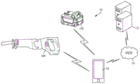
Fig. 1 shows a communication system 100. The communication system 100 includes a power tool device 102 and an external device 108. Each power tool device 102 (e.g., the reciprocating saw and the power tool battery pack 102b as the power tool 104) and the external device 108 may communicate wirelessly when they are within communication range of each other. Each power tool device 102 may communicate power tool status, power tool operation statistics, power tool identification, stored power tool usage information, power tool maintenance data, and the like. Thus, by using the external device 108, the user may access stored power tool usage or power tool maintenance data. Using this tool data, a user can determine how to use the power tool apparatus 102, whether to recommend maintenance or whether maintenance has been performed in the past, and identify faulty components or other causes that cause certain performance problems. The external device 108 may also send data to the power tool device 102 for power tool configuration, firmware updates, or send commands (e.g., turn on a work light). The external device 108 also allows the user to set operational parameters, safety parameters, select tool modes, etc. for the power tool device 102.
The external device 108 may be, for example, a smart phone (as shown), a laptop computer, a tablet computer, a Personal Digital Assistant (PDA), or another electronic device capable of wirelessly communicating with the power tool device 102 and providing a user interface. The external device 108 provides a user interface and allows the user to access and interact with tool information. The external device 108 may receive user input to determine operating parameters, enable or disable features, and the like. The user interface of the external device 108 provides an easy-to-use interface for a user to control and customize the operation of the power tool.
The external device 108 includes a communication interface compatible with the wireless communication interface or module of the power tool device 102. The communication interface of the external device 108 may include a wireless communication controller (e.g., a bluetooth module), or similar component. Thus, the external device 108 authorizes the user to access data associated with the power tool device 102 and provides a user interface so that the user can interact with the controller of the power tool device 102.
Additionally, as shown in fig. 1, the external device 108 may also share information obtained from the power tool device 102 with a remote server 112 connected via a network 114. The remote server 112 may be used to store data obtained from the external device 108, provide additional functionality and services to the user, or a combination thereof. In one embodiment, storing the information on remote server 112 allows a user to access the information from a plurality of different locations. In another embodiment, the remote server 112 may collect information about their power tool devices from various users and provide statistics or statistical measures to the users based on information obtained from different power tools. For example, remote server 112 may provide the following statistics: regarding the efficiency experienced by the power tool device 102, typical usage of the power tool device 102, and other relevant characteristics and/or measurements of the power tool device 102. The network 114 may include various network elements (routers, hubs, switches, cell towers, wired connections, wireless connections, etc.) for connecting to, for example, the internet, a cellular data network, a local network, or a combination thereof. In some embodiments, the power tool device 102 may be configured to communicate directly with the server 112 through an additional wireless interface or through the same wireless interface that the power tool device 102 uses to communicate with the external device 108.
The power tool device 102 is configured to perform one or more specific tasks (e.g., drilling, cutting, fastening, pressing, lubricant application, sanding, heating, grinding, bending, shaping, impacting, polishing, illuminating, etc.). For example, impact wrenches are associated with the task of generating a rotary output (e.g., driving a drill bit), while reciprocating saws are associated with the task of generating a reciprocating output motion (e.g., for pushing and pulling a saw blade).
Fig. 2 shows an example of a power tool apparatus 102, a reciprocating saw (here a power tool 104). While fig. 2 shows the power tool 104 as a saber saw, it should be understood that the present invention may be implemented on other types of reciprocating saws, including but not limited to jig saws, scroll saws, and rotary reciprocating saws. The power tool 104 defines a longitudinal axis a. The power tool 104 generally includes a shoe assembly 12, a body 14 having a motor 214, the motor 214 being powered by an electrical cord (AC version), a battery pack (DC version), or a compressed air source (pneumatic version). The drive mechanism 44 (i.e., transmission) converts the rotational motion of the motor 214 into reciprocating motion of the reciprocating spindle 18 to reciprocate the saw blade 20 in a direction generally parallel to the longitudinal axis a of the power tool 104. The saw blade 20 is held in place by a tool holder (e.g., a blade clamp 21) coupled to the reciprocating spindle 18. The power tool 104 also includes a handle assembly 22, the handle assembly 22 being positioned at a distal end of the body 14 opposite the shoe assembly. The handle assembly 22 includes a grip portion 24 and a trigger 212 adjacent the grip portion 24 for actuating a motor 214. The trigger 212 is positioned such that the user can actuate the trigger 212 using the same hand that holds the grip portion 24, for example, with the index finger 24. The power tool 104 also includes a mode key 208. The mode key 208 allows the user to select a mode of the power tool 104 and indicates to the user the currently selected mode of the power tool 104, as will be described in more detail below.
The shoe assembly 12 includes a shoe post 28 and a shoe 30. The shoe 30 is pivotally mounted on the distal end of the shoe post 28 remote from the main body 14. In other constructions, the cushion 30 may be fixedly mounted on the cushion post 28 or mounted on the cushion post 28 in other suitable manners. In other constructions, other types of shoe assemblies may be employed. The shoe assembly 12 is fixed relative to the body 14 of the power tool 104 and provides a guide surface 46 for the power tool 104 to rest on a workpiece (not shown) during a cutting operation. The shoe assembly 12 includes a longitudinally extending shoe post 28 extending generally parallel to a longitudinal axis a of the power tool 104, which is at least partially disposed within an aperture of the main body 14 of the power tool 104. The shoe post 28 is axially movable relative to the body 14 of the power tool 104 in a direction generally parallel to the axis a and includes a locking mechanism 32 for stabilizing the shoe assembly 12 in one of a plurality of axial positions relative to the body 14. For example, the locking mechanism 32 may include a ball detent system. In other constructions, other suitable types of locking mechanisms may be employed, such as magnets, cams, other types of detent mechanisms, and the like.
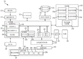
Fig. 3A shows a schematic of the power tool 104 including the motor 214. The motor 214 actuates the drive device 210 and allows the drive device 210 to perform a particular task. A main power source (e.g., a battery pack) 205 is coupled to the power tool 104 and provides power to energize the motor 214. The motor 214 is energized based on the position of the trigger 212. When the trigger 212 is depressed, the motor 214 is energized, and when the trigger 212 is released, the motor 214 is de-energized. In the illustrated embodiment, the trigger 212 extends partially down the length of the grip portion 24; however, in other embodiments, the trigger 212 extends down the entire length of the grip portion 24, or may be positioned elsewhere on the power tool 104. The trigger 212 is movably coupled to the grip portion 24 such that the trigger 212 moves relative to the tool housing. The trigger 212 is coupled to a push rod that may be engaged with a trigger switch 213 (see fig. 3A). When the user depresses the trigger 212, the trigger 212 moves in a first direction toward the grip portion 24. The trigger 212 is biased (e.g., with a spring) such that when the trigger 212 is released by a user, the trigger 212 moves in a second direction away from the grip portion 24. The push rod activates the trigger switch 213 when the user presses the trigger 212, and the trigger switch 213 is deactivated when the user releases the trigger 212. In other embodiments, the trigger 212 is coupled to an electrical trigger switch 213. In this embodiment, the trigger switch 213 may comprise, for example, a transistor. Additionally, for such electronic embodiments, the trigger 212 may not include a push rod for activating the mechanical switch. Rather, the electrical trigger switch 213 can be activated by, for example, a position sensor (e.g., a hall effect sensor) that relays information about the relative position of the trigger 212 to the tool housing or the electrical trigger switch 213. The switch 213 outputs a signal indicating the position of the flip-flop 212. In some cases, the signal is binary and indicates that the trigger 212 is pressed or released. In other cases, the signal indicates the position of the trigger 212 with greater accuracy. For example, the flip-flop switch 213 may output various 0 to 5 volt analog signals depending on the degree to which the flip-flop 212 is pressed. For example, a 0V output indicates that the flip-flop 212 is released, a 1V output indicates that the flip-flop 212 is pressed 20%, a 2V output indicates that the flip-flop 212 is pressed 40%, a 3V output indicates that the flip-flop 212 is pressed 60%, a 4V output indicates that the flip-flop 212 is pressed 80%, and a 5V output indicates that the flip-flop 212 is pressed 100%. The signal output by the trigger switch 213 may be analog or digital.
As also shown in fig. 3A, the power tool 104 further includes a power source 205, a switching network 216, a sensor 218, an indicator 220, a power input unit 224, a controller 226, a wireless communication controller 250, and a backup power source 252. The power source 205 supplies power to the power input unit 224. The power input unit 224 includes active and/or passive components (e.g., voltage step-down controllers, voltage converters, rectifiers, filters, etc.) to regulate or control power from the power source 205 through the wireless communication controller 250 and the controller 226.
In some embodiments, the power tool 104 includes a battery pack interface (not shown). In this embodiment, the battery pack interface is coupled to the controller 226 and to the battery pack. The battery pack interface includes a combination of mechanical (e.g., battery pack receiving portion) and electronic components configured and operable for engaging (e.g., mechanically, electrically, and communicatively connecting) the power tool 104 with the battery pack 102 b. The battery pack interface is coupled to the power input unit 224. The battery pack interface transmits power received from the battery pack to the power input unit 224.
The switching network 216 enables the controller 226 to control the operation of the motor 214. Typically, when the trigger 212 is depressed (as indicated by the output of the trigger switch 213), current is provided from the battery pack interface to the motor 214 via the switching network 216. When the trigger 212 is not depressed, no current is supplied to the motor 214 from the battery pack port.
In response to the controller 226 receiving an activation signal from the trigger switch 213, the controller 226 activates the switch network 216 to provide power to the motor 214. The switching network 216 controls the amount of current available to the motor 214, thereby controlling the speed and torque output of the motor 214. The switching network 216 may include a number of FETs, bipolar transistors, or other types of electrical switches. For example, the switching network 216 may include a six FET bridge that receives a Pulse Width Modulated (PWM) signal from the controller 226 to drive the motor 214.
The sensor 218 is coupled to the controller 226 and communicates various signals indicative of different parameters of the power tool 104 or the motor 214 to the controller 226. The sensors 218 include a hall sensor 218a, a current sensor 218b, a vibration sensor 218c, a distance sensor 218d, a shoe contact sensor 218e, and other sensors, such as one or more voltage sensors, one or more temperature sensors, and one or more torque sensors. The specific function of the sensor 218 will be described in more detail below.
Each hall sensor 218a outputs motor feedback information to the controller 226, such as an indication (e.g., a pulse) as the magnet of the motor rotor rotates on the surface of the hall sensor 218 a. Based on the motor feedback information from the hall sensor 218a, the controller 226 can determine the position, speed, and acceleration of the rotor. In response to the motor feedback information and the signal from the trigger switch 213, the controller 226 sends a control signal to control the switching network 216 to drive the motor 214. For example, by selectively enabling and disabling the FETs of the switching network 216, power received via the power supply 205 is selectively applied to the stator coils of the motor 214 to cause rotation of the rotor thereof. The controller 226 uses the motor feedback information to ensure that the control signals are properly timed to the switching network 216 and, in some cases, provides closed loop feedback to control the speed of the motor 214 at a desired level.
The indicator 220 is also coupled to the controller 226 and receives control signals from the controller 226 to turn on and off or otherwise communicate information based on different states of the power tool 104. The indicator 220 includes, for example, one or more light emitting diodes ("LEDs") or a display screen. The indicator 220 may be configured to display a status of the power tool 104 or information related to the power tool 104. For example, the indicator 220 is configured to indicate a measured electrical characteristic of the power tool 104, a status of the power tool 104, and a mode of the power tool 104 (discussed below). The indicator 220 may also include elements that convey information to the user through audible or tactile outputs.
As described above, the controller 226 is electrically and/or communicatively connected to the various modules or components of the power tool 104. In some embodiments, the controller 226 includes a plurality of electrical and electronic components that provide power, operational control, and protection to the controller 226 and/or components and modules within the power tool 104. For example, the controller 226 includes, among other things, a processing unit (e.g., a microprocessor, microcontroller, or other suitable programmable device), a power tool memory 232, an input unit 234, and an output unit 236. The processing unit, here electronic processor 230, includes, among other things, a control unit 240, an arithmetic logic unit ("ALU") 242, and a plurality of registers 244 (shown in fig. 3A as a set of registers). In some embodiments, the controller 226 is partially or completely implemented on a semiconductor (e.g., a field programmable gate array [ "FPGA" ] semiconductor) chip, such as a chip developed through a register transfer level ("RTL") design process.
The power tool memory 232 includes, for example, a program storage area 233a and a data storage area 233 b. The program storage area 233a and the data storage area 233b can include a combination of different types of memory, such as read only memory ("ROM"), random access memory ("RAM") (e.g., dynamic RAM [ "DRAM" ], synchronous DRAM [ "SDRAM" ], etc.), electrically erasable programmable read only memory ("EEPROM"), flash memory, a hard disk, an SD card, or other suitable magnetic, optical, physical, or electronic memory devices. The electronic processor 230 is connected to the power tool memory 232 and executes software instructions that can be stored in RAM of the power tool memory 232 (e.g., during execution), ROM of the power tool memory 232 (e.g., typically permanently), or another non-transitory computer-readable medium, such as another memory or disk. Software included in embodiments of the power tool 104 may be stored in the power tool memory 232 of the controller 226. The software includes, for example, firmware, one or more applications, program data, filters, rules, one or more program modules, and other executable instructions. The controller 226 is configured to retrieve from memory and execute, among other things, instructions related to the control processes and methods described herein. The controller 226 is also configured to store power tool information on the power tool memory 232, including operational data, information identifying the type of tool, a unique identifier for a particular tool, and other information related to the operation or maintenance of the power tool 104. Tool usage information (e.g., current level, motor speed, motor acceleration, motor direction, etc.) may be captured or inferred from the data output by the sensors 218. The user may then access such power tool information using the external device 108. In other constructions, the controller 226 includes additional, fewer, or different components.
As shown in fig. 3B, the wireless communication controller 250 includes a radio transceiver and antenna 254, a wireless communication controller memory 256, a wireless communication controller processor 258, and a Real Time Clock (RTC) 260. The radio transceiver and antenna 254 operate together to send wireless messages to the external device 108 and the wireless communication controller processor 258 and to receive wireless messages from the external device 108 and the wireless communication controller processor 258. The wireless communication controller memory 256 may store instructions to be implemented by the wireless communication controller processor 258 and/or may store data relating to communications between the power tool 104 and the external communication device 108, etc. The wireless communication controller processor 258 for the wireless communication controller 250 controls wireless communication between the power tool 104 and the external device 108. For example, a wireless communication controller processor 258 associated with the wireless communication controller 250 buffers input and/or output data, communicates with the controller 226, determines communication protocols and/or settings used in wireless communication.
In the illustrated embodiment, the wireless communication controller 250 is a bluetooth controller. The bluetooth controller communicates with the external device 108 using the bluetooth protocol. Thus, in the illustrated embodiment, the external device 108 and the power tool 104 are within communication range of each other (i.e., in proximity) as they exchange data. In other embodiments, wireless communication controller 250 communicates over different types of wireless networks using other protocols (e.g., Wi-Fi, cellular protocols, proprietary protocols, etc.). For example, the wireless communication controller 250 may be configured to communicate over a wide area network or a local area network, such as the internet, via Wi-Fi, or over a piconet (e.g., using infrared or NFC communications). Communications via the wireless communication controller 250 may be encrypted to protect data exchanged between the power tool 104 and the external device/network 108 from third parties.
The wireless communication controller 250 is configured to receive data from the power tool controller 226 and relay the information to the external device 108 via the transceiver and antenna 254. In a similar manner, the wireless communication controller 250 is configured to receive information (e.g., configuration and programming information) from the external device 108 via the transceiver and antenna 254 and relay the information to the power tool controller 226.
The Real Time Clock (RTC)260 increments and maintains time independent of other power tool components. The RTC 260 receives power from the power source 205 when the power source 205 is connected to the power tool 104, and the RTC 260 receives power from the backup power source 252 when the power source 205 is not connected to the power tool 104. The RTC 260, with a clock that is independently powered, enables time stamping of operational data (stored in the power tool memory 232 for later export) and security features whereby a user sets a lock-out time and the tool is locked when the time of the RTC 260 exceeds the set lock-out time.
The power tool memory 232 stores various identification information of the power tool 104, including a Unique Binary Identifier (UBID), an ASCII serial number, an ASCII alias, and a decimal directory number. The UBID both uniquely identifies the type of tool and provides a unique serial number for each power tool 104. Additional or alternative techniques for uniquely identifying the power tool 104 are used in some embodiments.
Fig. 4 shows a more detailed view of the mode key 208. Mode key 208 is a user interface on the foot of tool 104. The mode key 208 includes a mode selection switch 290 and a mode indicator LED block 292 having mode indicators 294a-e, each mode indicator 294a-e including one of the LEDs 296a-e (see FIG. 3A) and an associated one of the indicator symbols 298a-e (e.g., "1", "2", "3", "4" and a radio wave symbol). When the LED is enabled, the associated indicator symbol 298 is illuminated. For example, when the LED 296a is activated, a "1" (indicator 298a) is illuminated.
The power tool 104 has five selectable modes (one, two, three, four, and adaptive), each associated with a different one of the mode indicators 294 a-e. The mode select switch 290 is a button that cycles through five selectable modes (e.g., modes 1, 2, 3, 4, 5, 1, 2, etc.) upon each press. The adaptive mode is represented by an indication symbol 298e (radio wave symbol). In the adaptive mode, the user is able to configure the power tool 104 via the external device 108, as described in further detail below. For example, the external device 108 may send a new configuration to the power tool 104, which may be stored in the configuration library 302. In other embodiments, the power tool 104 has more or fewer modes, and the mode selection switch 290 can be a different type of switch, e.g., a slide switch, a rotary switch, etc.
Referring to fig. 5, each of modes one, two, three, and four are associated with a mode configuration data block ("mode configuration") 300a-d, respectively, which is stored in the power tool memory 232 in the (mode) configuration repository 302. Each mode configuration includes configuration data that defines the operation of the tool 104 when the user activates the tool (e.g., when the trigger 212 is pressed). For example, each configuration may enable different features to be performed by the power tool 104. Each configured feature may be enabled and disabled and parameters related to the feature may be adjusted by a user, as explained in more detail below. For example, a particular mode configuration may specify motor speed, when to stop the motor, duration and intensity of the operating lights (not shown), and other operating characteristics. The adaptive mode is associated with a temporary mode configuration 300e that is saved in the power tool memory 232. Also stored in the power tool memory 232 is tool operational data 304, which includes, for example, information regarding the use of the power tool 104 (e.g., obtained via the sensor 218), information regarding maintenance of the power tool 104, power tool trigger event information (e.g., whether and when a trigger is pressed and the amount of the press). Additionally, the power tool memory 232 may store user adjustable features that may be implemented on multiple modes on the power tool 104. The user may adjust the parameters of these features similar to how the user adjusts the parameters of the configuration, as explained in more detail below.
The external device 108 includes an external device memory 310 that stores core application software 312, tool mode configuration 314, temporary configuration data 316, tool interface 318, tool data 320, the tool data 320 including a received tool identifier 322 and received tool usage data 324 (e.g., tool operation data). The external device 108 also includes an external device processor 330, a touch screen 332, and an external wireless communication controller 334. The external device processor 330 and the external device memory 310 may be part of a controller having similar components as the controller 226 of the power tool 104. The touch screen 332 allows the external device 108 to output visual data to the user and receive user input. Although not shown, the external device 108 may include additional user input devices (e.g., buttons, dials, toggle switches, and a microphone for voice control) as well as additional user outputs (e.g., a speaker and haptic feedback elements). Additionally, in some cases, the external device 108 has a display without touch screen input capability and receives user input via other input devices (e.g., buttons, dials, and toggle switches). The external device 108 wirelessly communicates with the wireless communication controller 250 via the external wireless communication controller 334, for example, using bluetooth or Wi-Fi protocols. The external wireless communication controller 334 also communicates with the server 112 through the network 114. The external wireless communication controller 334 includes at least one transceiver to enable wireless communication between the external device 108 and the wireless communication controller 250 of the power tool 104 or the server 112 over the network 114. In some cases, the external wireless communication controller 334 includes two separate wireless communication controllers, one for communicating with the wireless communication controller 250 (e.g., using bluetooth or Wi-Fi communication) and one for communicating over the network 114 (e.g., using Wi-Fi or cellular communication).
The server 112 includes a server processor 340 that communicates with the external device 108 over the network 114 using a network interface 342. The communication links between the network interface 342, the network 114, and the external wireless communication controller 334 may include various wired and wireless communication paths, various network components, and various communication protocols. The server 112 also includes a server memory 344, the server memory 344 including a tool configuration library 346 and tool data 348.
Returning to the external device 108, the core application software 312 is executed by the external device processor 330 to generate a Graphical User Interface (GUI) on the touch screen 332 to enable a user to interact with the power tool 104 and the server 112. In some embodiments, a user may use external device 108 to access a repository of software applications (e.g., "application store app store" or "application market app markplace") to locate and download core application software 312 (which may be referred to as an "app"). In some embodiments, the tool mode configuration 314, the tool interface 318, or both may be bundled with the core application software 312 such that, for example, downloading an "app" includes downloading the core application software 312, the tool mode configuration 314, and the tool interface 318. In some embodiments, the app is obtained using other techniques, such as downloading from a website using a web browser on the external device 108. As will become apparent from the description below, in at least some embodiments, the app on the external device 108 provides a single entry point to the user for controlling, accessing, and/or interacting with a variety of different types of tools. This approach is in contrast to, for example, a unique app for each type of tool or a small grouping of related types of tools.
FIG. 6 shows a nearby device screen 350 of the GUI on the touch screen 332. The nearby device screen 350 is used to identify and communicatively pair with the power tool 104 within wireless communication range of the external device 108 (e.g., a local power tool). For example, in response to the user selecting the "scan" input 352, the external wireless communication controller 334 scans the radio wave communication spectrum used by the power tools 104 and identifies any power tools 104 within broadcast range (e.g., broadcasts their UBID and other limited information). The identified broadcasting power tool 104 is then listed on the nearby device screen 350. As shown in fig. 6, in response to the scan, three broadcasting power tools 104 (broadcasting tools 354a-c) are listed in the identified tools list 356. In some embodiments, if the power tool 104 has been communicatively paired with a different external device, the power tool 104 does not broadcast and, therefore, even though the power tool 104 may be near (within wireless communication range of) the external device 108, it is not listed in the identified list of tools 356. The external device 108 is operable to be paired with the tool 354 in a connectable state. The external device 108 provides a visual status indication 358 in the identified tools list 356 to indicate whether the tool 354 being broadcast is in a connectable state or a broadcast state. For example, the visual status indication 358 of the tool may be displayed in one color when the tool is in the connectable state and in another color when the tool is not in the connectable state. The UBID received from the tools 354 is used by the external device 108 to identify the tool type of each tool 354.
From the nearby device screen 350, the user may select one of the tools 354 from the identified list of tools 356 to communicatively pair with the selected tool 354. Each type of power tool 104 with which the external device 108 may communicate includes: an associated tool graphical user interface (tool interface) stored in tool interface 318. Once communication pairing occurs, core application software 312 accesses tool interface 318 (e.g., using the UBID) to obtain an applicable tool interface for the paired tool type. The touch screen 332 then displays the applicable tool interface. The tool interface includes a series of screens that enable a user to obtain tool operational data, configuration tools, or both. Although some of the screens and options of a tool interface are common to multiple tool interfaces of different tool types, typically, each tool interface includes screens and options specific to the relevant type of tool. The power tool 104 has limited space for user input buttons, triggers, switches, and dials. However, the external device 108 and the touch screen 332 provide the user with the ability to map additional functions and configurations to the power tool 104 to change the operation of the tool 104. Thus, in effect, the external device 108 provides an extended user interface for the power tool 104 to provide further customization and configuration of the power tool 104, rather than through physical user interface components on the tool as may be possible or desirable. Examples of aspects and benefits of extending the user interface are further explained below.
Fig. 7 shows a home screen 370 of the tool interface when the power tool 104 is a reciprocating saw. The home screen 370 includes an icon 371 for a particular paired power tool 104, which may be the same as the icon shown in the list 356. The home screen 370 also includes a disconnect input 372 that enables a user to break the communication pairing between the external device 108 and the paired power tool 104. The home screen 370 also includes four selectable options: tool control 374, management configuration 376, identification tool 378, and factory reset 379. The selection recognition tool 378 sends a command to the paired power tool 104 requesting that the paired power tool 104 provide a user-perceptible indication, such as flashing an operating light, a light of the indicator 220, flashing an LED, emitting an audible beep using a speaker of the indicator 220, and/or causing the tool to vibrate using the motor 214. The user may then identify the particular tool in communication with the external device 108.
Selecting the tool control 374 causes a control screen of the tool interface to be displayed, such as the control screens shown in fig. 8A-8B, which includes a top 380a and a bottom 380B. Generally, the control screens shown depend on the particular type of configuration. In other words, generally, each type of mode configuration has a specific control screen. Each control screen has certain customizable parameters that together form a schema configuration. The particular control screen displayed on the external device 108 when the tool control 374 is selected is the currently selected mode configuration (e.g., one of the mode configurations 300 a-e) of the power tool 104. To this end, upon selection of the tool control 374, the external device 108 requests and receives the currently selected one of the mode configurations 300a-e from the power tool 104. The external device 108 identifies the mode configuration type of the selected one of the mode configurations 300a-e, generates an appropriate control screen for the mode configuration type, and populates various parameter settings according to the settings from the received mode configuration.
When in the adaptive mode, the currently selected mode configuration displayed on the control screen is the temporary mode configuration 300 e. In addition, when the power tool 104 is in the adaptive mode, the power tool 104 operates according to the temporary mode configuration 300 e. The source of the configuration data (and the content displayed on the control screen) in the temporary mode configuration 300e is varied. Initially, upon entering the adaptive mode via the mode select switch 290, the mode configuration 300a (associated with mode 1) is copied into the temporary mode configuration 300e of the power tool 104. Thus, after the user enters the power tool 104 into the adaptive mode using the mode select switch 290, the power tool 104 initially operates when the trigger is pulled, as with the currently selected mode 1 (mode configuration 300 a). In addition, when the control screen displays the mode configuration saved as the temporary mode configuration 300e, the mode configuration 300a just copied to the temporary mode configuration 300e is displayed on the control screen.
In some embodiments, upon first entering the adaptive mode, another mode configuration (e.g., 300b-d) is copied into the temporary mode configuration 300e and provided (as the temporary mode configuration 300e) to the external device 108 for populating the control screen. In another embodiment, upon selection of the tool control 374, the control screen shown is a default control screen with default configuration data for a particular type of tool, and the external device 108 does not first obtain configuration data from the power tool 104. In these cases, the default mode configuration is sent to the power tool 104 and saved as the temporary mode configuration 300 e.
Further, assuming that the power tool 104 is in the adaptive mode, the user may select a new configuration data source for the temporary file after the external device 108 initially loads the control screen (e.g., control screen) when selecting the tool control 374. For example, upon selection of one of the mode configuration buttons 400 (e.g., mode 1, mode 2, mode 3, or mode 4), the associated mode configuration 300a-d is saved as a temporary mode configuration 300e and sent to the external device 108, and the control screen is populated (according to the mode configuration type and mode configuration parameters). In addition, assuming that the power tool 104 is in the adaptive mode, the user can select the mode configuration type using the setting selector 401. Upon selection of the settings selector 401, a list of available configurations 402 (configuration list) for a particular type of paired power tool 104 is displayed (see, e.g., fig. 9). The configuration list 402 includes configurations 404 obtained from the tool configuration 314 and/or from the tool configuration library 346 over the network 114. These listed configurations 404 may include default configurations and custom configurations previously generated and saved by the user, as described in more detail below. Upon selection of one of the tool configurations 404, the selected configuration 404 and its default parameters are shown on the control screen of the external device 108, and the currently configured configuration 404 is sent to the power tool 104 and saved as the temporary mode configuration 300 e. Thus, upon further trigger pulls, the power tool 104 will operate according to the selected one of the tool configurations 404.
When the adaptive mode is currently selected on the power tool 104, as shown by reference numeral 298e (fig. 4), the user is able to configure (e.g., change some parameters of the temporary mode configuration 300e) the power tool 104 using the control screen. When the power tool 104 is in one of the other four tool modes (as indicated by one of the indicator symbols 298 a-d), the power tool 104 is not currently configurable via the control screen. For example, in fig. 10, a control screen 381 is shown when the power tool is not currently in the adaptive mode. Here, the control screen 381 is similar to the control screen, but includes a message 382 indicating that the tool is not in the adaptive mode, and a wireless symbol 384 is displayed in gray as another indication that the power tool is not in the adaptive mode. Thus, when the power tool 104 is not in the adaptive mode and the user selects one of the mode configuration buttons 400, the power tool 104 provides the mode configuration of the associated mode selected by the user, but does not override the temporary mode configuration 300e with that mode configuration. Thus, when the power tool 104 is not in the adaptive mode, the mode configuration of the power tool 104 is not updated.
Referring back to fig. 8A-8B, when the power tool 104 is in the adaptive mode and the user selects the tool control 374 on the home screen, the user can configure the configuration data of the power tool 104 using the control screen of the tool interface. For example, through the control screen, the user can configure the current configuration data of the temporary mode configuration 300e of the power tool 104. As shown, the user can adjust the launch speed using the speed text box 390 or the speed slider 391; adjust the ending speed using the speed text box 392 or the speed slider 393; adjust a trigger acceleration (ramp-up) period with the slider 394; adjust the worklight duration with slider 395a, worklight text box 395b and "normally open" switch 395 c; and adjust operating light intensity using operating light brightness option 396.
In some embodiments, the external device 108 and the power tool 104 implement real-time updates of the temporary mode configuration 300 e. When updated in real time, the temporary mode configuration 300e of the power tool 104 is updated as changes in parameters are made on the control screen without requiring a subsequent saving step or actuation by the user on the GUI of the external device 108 or on the power tool. In other words, when updated in real-time, the external device 108 updates the temporary mode configuration 300e on the power tool 104 in response to receiving a user input to change one of the parameters (rather than in response to a user input to save the temporary mode configuration 300 e). For example, with respect to fig. 8A, the activation speed of the power tool 104 is set to 2900 Revolutions Per Minute (RPM). When updating in real-time, if the user slides the speed slider 391 to the right by dragging his/her finger across the speed slider 391 and then removing his/her finger from the touch screen 332 of the external device 108 when the new speed is reached, the external device 108 sends the newly selected activation speed to the power tool 104 to update the temporary mode configuration 300e when the user's finger is removed from the screen without requiring the user to further press a button or other actuation. Real-time updates are also applicable to control other parameters on the screen, such as final speed, trigger acceleration period, and work light parameters. Real-time updates enable quick customization of the power tool 104 so that a user can quickly test and adjust various configuration parameters with fewer buttons. In contrast to real-time updates, in some embodiments, after sliding the speed slider 391 to the new speed, the user must press a save button (e.g., save button 408) to effect an update of the launch speed parameter on the temporary mode configuration 300 e.
The user can also save the mode configuration to the power tool 104 via the control screen. More specifically, the user can override one of the schema configurations 300a-d in the configuration library 302 using the schema configuration specified on the control screen. To save the mode configuration generated by the user via control screen 308, the user selects save button 408. As shown in FIG. 11, pressing the Save button causes the core application to generate a Save prompt 410 requesting the user to name the created schema configuration and specify which schema configuration 300a-d is to be overridden by the generated schema configuration. In response to the user input, the external device 108 transmits the generated mode configuration to the power tool 104. The electronic processor 230 receives the generated schema configuration and overrides the schema configuration in the repository of schema configurations 302 designated for overriding by the user with the generated schema configuration. For example, in fig. 11, the user has named the generated schema configuration "platform Mode Deck Mode" and has designated that electronic processor 230 overrides schema configuration 300a (associated with schema "1") with the generated "Deck Mode" schema configuration. In some embodiments, the user may select to override more than one mode configuration 300a-e with the generated mode configuration by selecting a plurality of mode tabs prior to selecting the save button 412. In some embodiments, the user may select: by not selecting any mode tab, any mode configuration 300a-e is not overridden with the generated mode configuration until the save button 412 is selected. In this embodiment, the generated schema configuration is stored in the configuration library 346 on the server 112, rather than on the power tool 104. Overlaying a configuration (old configuration) with another configuration (new configuration) may include, for example: storing the new configuration in the memory at a location for storing the old configuration, thereby erasing the old configuration and replacing it in the memory with the new configuration, or may comprise storing the new configuration in another location in the memory and updating the configuration pointer to point to an address in the memory having the new configuration instead of the address in the memory having the old configuration.
As described above, in some embodiments, the external device 108 cannot override the configured data unless the power tool 104 is in the adaptive mode (see fig. 10). This aspect prevents a potentially malicious individual other than the user currently operating the power tool 104 from adjusting the tool parameters of the power tool 104 unless the user places the power tool 104 in the adaptive mode. Thus, a user of the power tool 104 can prevent others from adjusting the parameters by operating the power tool 104 in one of the other four modes. In some embodiments, to implement this aspect, a hardware or firmware-based interlock prevents the electronic processor 230 from writing to the configuration library 302 unless the power tool 104 is in the adaptive mode. Further, a hardware or firmware based interlock prevents the electronic processor 230 from writing to the configuration library 302 while the power tool 104 is in operation. The electronic processor 230 can detect whether the power tool 104 is in operation based on the depression of the trigger 212 or the output from the hall sensor 218a indicating motor rotation. Thus, even when the power tool 104 is in the adaptive mode, if the power tool 104 is currently operating, the electronic processor 230 will not update or write into the configuration library 302 even when the power tool 104 is in the adaptive mode and the external device 108 communicates the generated configuration to the power tool 104 (e.g., in response to the user selecting the save button 408).
Further, in some embodiments, the electronic processor 230 outputs a signal to the external device 108 via the wireless communication controller 250 indicating whether the power tool 104 is currently operating. Further, when the power tool 104 is currently operating, the external device 108 provides an indication to the user, such as a color change (e.g., to red) or flashing by the wireless symbol 384 and a message. Further, similar to the control screen 381 of fig. 10, when the external device 108 receives an indication that the power tool 104 is currently operating, the ability to update parameters through the control screen is prevented.
Returning to fig. 7, selection of the factory reset 379 on the home screen 370 causes the external device 108 to obtain a default mode configuration from the tool mode configuration 314 or from the tool configuration library 346 on the server 112 and provide the default configuration to the power tool 104, which in turn overrides the configuration library 302 with the default mode configuration.
The home screen 370 is similar in appearance and feel for all, a plurality, or a few of the tool interfaces 318, although the icons 371 may be customized for a particular tool interface based on the particular power tool that is paired with the external device 108. In addition, the options listed below the icon may add a "get data" option that enables the user to select and obtain operational data from the tool for display on external device 108 and/or transmission to server 112 for storage as part of tool data 348. Additionally, in the event that a particular tool is not intended to be configured by the external device 108, the tool control 374 and management configuration 376 options may not be included on the home screen 370.
In some embodiments, an adaptive mode switch separate from the mode select switch 290 is provided on the power tool 104. For example, the LED 296e (fig. 3A) may be a combined LED push button switch, whereby upon a first press of the combined LED push button switch, the power tool 104 enters an adaptive mode, and upon a second press of the switch, the power tool 104 returns to the mode (e.g., mode 1) in which it was prior to the first press. In this case, the mode select switch 290 may cycle through modes 1-4, but not through the adaptive mode. Further, some combination of trigger pulls and/or placing the forward/reverse selector in a particular position (e.g., neutral) may cause the power tool 104 to enter and exit the adaptive mode.
Returning to the concept of a schema configuration (e.g., configuration), the schema configuration includes one or more features, which may further include one or more parameters. For example, returning to fig. 8A-8B, the mode configuration shown is a cut-in cut configuration having a cut-in cut feature and an operating light control feature. The plunge cut characteristics included the following parameters: start speed, final speed, and trigger acceleration period. The work light control function includes a work light duration parameter and a work light brightness parameter. Some configurations (e.g., the customized cutting configuration shown in fig. 22A and 22B) include features (e.g., a plunge cut feature and a cut stop feature), which also include parameters. The particular features and parameters that may be customized on the control screen of the external device 108 vary based on the mode configuration type.
The control screen of tool interface 318 places limits on the values that a user may enter for a particular parameter. For example, as shown in fig. 8A, the activation speed cannot be set at 2900RPM or more or 360RPM or less. The power tool 104 also includes a boundary check module, e.g., in firmware stored on the power tool memory 232 and executed by the electronic processor 230. Upon receiving a new configuration from the external device 108 for saving in the configuration repository 302, the bounds checking module confirms that each parameter is within the maximum and minimum bounds, or is a valid value for the particular parameter. For example, the bounds checking module determines that: the plunge cut configuration is set with a start-up speed in the range of 360RPM to 2900 RPM. In some cases, the bounds check module confirms that the currently configured parameter value of the power tool is within an acceptable range each time the trigger is pulled. To perform the boundary check, the firmware may include a list of parameters and applicable maximum and minimum boundaries stored, for example, in a table, and the electronic processor 230 is operable to perform a comparison with the table data to determine if the parameter values are within an acceptable range. The border check module provides an additional layer of security against configuration, functionality, and parameter values that are maliciously generated or corrupted.
When the bounds check module determines that the parameter value is outside of the acceptable range, the controller 226 is operable to: an alarm message (which may be displayed as text on the touch screen 332) is output to the external device 108 to indicate an error, to actuate the indicator 220, the LEDs 296a-e, to cause the motor to vibrate, or a combination thereof.
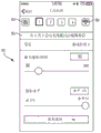
On some control screens of the tool interface 318, parameter assist blocks are provided. The parameter assistance block includes an operating factor input that allows the user to specify the following details: details of the workpiece on which the power tool operates (e.g., material type, thickness, and/or hardness), details of the fastener driven by the power tool (e.g., material type, screw length, screw diameter, screw type, and/or head type), and/or details of the output unit of the power tool (e.g., saw blade type, saw blade teeth count, bit type, and/or bit length). For example, the optimal configuration control screen 1200 includes a parameter assistance block 1205, as shown in FIG. 12A. The parameter assistance block 1205 includes an operating factor input that allows the user to specify the material being cut, the thickness of the material being cut, and the type or style of the blade 20 (e.g., No. 12345, wood cutting blade, metal cutting blade, blade length, number of teeth, roughing blade, etc.). In some embodiments, by selecting the parameter assistance block 1205, a parameter assistance screen is generated on which the user can specify each work factor input by cycling through values using the touch screen 332. After completing the input of the input work factor, the external device 108 adjusts the parameters of the configuration. For example, as shown in fig. 12A, the value of the motor speed parameter 1210 is adjusted by the external device 108 based on the duty factor input of the parameter assist block 1205. The external device 108 may adjust the motor speed parameter 1210 using a lookup table that includes parameter values corresponding to user inputs in the parameter assistance block 1205. The user can further adjust some or all of the parameters if desired (e.g., using a slider on the GUI as shown in fig. 12A).
Different configuration and feature types are provided with different parametric auxiliary blocks, and each parametric auxiliary block may include an operating factor input appropriate for the particular configuration or feature type. Further, one or more boundary values of the parameters on the control screen 1200 may be adjusted by the external device 108 based on the work factor input of the parameter assistance block 1205. For example, the maximum speed selectable by the user for the motor speed parameter 1210 may be adjusted based on input received by the parameter assistance block 1205.
In fig. 8A, the parameters of the plunge cut configuration include two user-adjustable parameters (motor speed) of the same parameter type, which are applicable to different stages (or zones) of a single tool operation. More specifically, for the plunge cut configuration, the user is operable to specify on the control screen: a starting motor speed during a beginning phase of the cutting operation, and a final speed during a final/finishing phase of the cutting operation. The controller 226 determines when and switches between different stages of the cutting operation, as will be described in more detail below. In some embodiments, the user-selected speed is considered the maximum speed value at various stages of the plunge cut configuration (and in other configurations and features). Thus, in these embodiments, the speed of the motor 214 varies based on the amount of depression of the trigger 212, but the controller 226 ensures that the motor 214 does not exceed the user-selected speed at various stages.
Other configuration types and features may be used with the power tool 104. Other configuration types include custom cut configurations, as will be described in more detail below. Some features available with the power tool 104 that may be selectively enabled in some configurations include a cut stop feature, a blind cut feature, a wave cut feature, and a vibration dampening feature. As described above, for each configuration, a unique control screen of the associated tool interface 318 may be set on the GUI of the external device 108. Using the control screen, a user can selectively enable and disable features within the configuration, and can adjust parameters and functions of the configuration. Based on the parameters and characteristics of the above-described configuration, the controller 226 generates specific control signals to the FETs through the switching network 216 to achieve a desired direction of rotation, number of rotations, speed of rotation, and/or maximum speed of rotation of the motor 214. The control screen is used for the description of the following: a cut stop feature, a blind cut feature, a wave cut feature, and a vibration damping feature. Each of these control screens is displayed as being associated with a single feature. However, in some embodiments, two or more features and corresponding parameters are included on a single control screen to generate a configuration having more than one feature. For example, fig. 14 shows a control screen for controlling the cut stop feature, while fig. 22B shows the cut stop feature as part of the control screen for customizing the cutting configuration.
The plunge cut feature allows the motor 214 of the power tool 104 to operate at different speeds while cutting material, and may also be referred to as a soft start feature. In particular, the plunge cut feature allows the motor 214 to initially operate at a start-up speed to capture the material to be cut. After the power tool 104 begins cutting the material, the motor speed is increased to a final speed during the trigger acceleration. Controlling the motor 214 in this manner facilitates more efficient cutting by the power tool 104. As shown in the control screens of the GUIs of fig. 8A and 8B, the plunge cut feature has parameters that can be adjusted by the user (i.e., using a slider on the GUI or entering a value into a text box). Parameters of the plunge cut configuration including the plunge cut feature include start-up speed, final speed, trigger acceleration period, worklight duration, and worklight brightness. In some embodiments, parameters of the plunge cut configuration (as well as other configurations and features) may vary. As described above, the power tool 104 receives a plunge cut configuration including specified parameters, for example, from the external device 108.
Fig. 13A illustrates a flow chart of a method 1300 of implementing a plunge cut feature on a power tool 104. At block 1302, the wireless communication controller 250 receives a plunge cut configuration from the external device 108 that includes parameters of the plunge cut feature. At block 1305, the electronic processor 230 determines that the trigger 212 has been pressed and starts the motor 214. At block 1310, the electronic processor 230 sets the speed of the motor 214 to the start speed and starts a timer. At block 1315, the electronic processor 230 determines whether a start speed period has elapsed since the user pulled the trigger 212 (e.g., by comparing a timer to the start speed period). At block 1315, when the startup speed period has not elapsed since the user pulled the trigger 212, the electronic processor 230 waits until the startup speed period has elapsed. When the electronic processor 230 determines that the startup speed period has elapsed, the electronic processor 230 accelerates the motor speed to a final speed according to a trigger acceleration period at block 1320. For example, if the trigger acceleration period is set to "off (i.e., zero)" by the control screen, the motor speed increases substantially immediately to the final speed. However, if the trigger acceleration period is set to a non-zero value (e.g., 0.5 seconds), the motor speed is increased to a final speed during the non-zero time period. For example, the acceleration may be linear or exponential. Although not shown in fig. 8A and 8B, in some embodiments, the start speed period may be a user adjustable parameter on the control screen.
Fig. 13B illustrates a flow chart of an alternative method 1350 of implementing a plunge cut feature on the power tool 104. At block 1352, the wireless communication controller 250 receives a plunge cut configuration from the external device 108 that includes parameters of the plunge cut feature. At block 1355, the electronic processor 230 determines that the trigger 212 has been pressed and starts the motor 214. At block 1360, the electronic processor 230 sets the speed of the motor 214 to the start-up speed and begins monitoring the current drawn by the motor 214. At block 1365, the electronic processor 230 determines whether the motor current exceeds a predetermined capture threshold (i.e., whether the blade 20 has begun to capture the material being cut). The electronic processor 230 can monitor the current drawn by the motor 214 using the current sensor 218 b. When the motor current does not exceed the predetermined capture threshold, at block 1365, the electronic processor 230 waits until the motor current exceeds the predetermined capture threshold. When the electronic processor 230 determines that the motor current exceeds the predetermined capture threshold, the electronic processor 230 accelerates the motor speed to a final speed according to a trigger acceleration period at block 1370. Although not shown in fig. 8A and 8B, in some embodiments, the predetermined capture threshold may be a user adjustable parameter on the control screen to allow the user to adjust the sensitivity of causing the motor speed to vary.
Further, in some embodiments of the plunge cut configuration, the electronic processor 230 may monitor the rotational acceleration of the rotor and determine that the blade 20 has begun to capture the material being cut when the rotational acceleration of the rotor decreases below a predetermined rotational acceleration threshold (e.g., decelerates at a particular level). Additionally, in some embodiments of the plunge cut configuration, the electronic processor 230 may monitor the acceleration of the change in motor current (i.e., the change in the rate of change of the motor current over a predetermined period of time). In this embodiment, the electronic processor 230 determines that the blade 20 has begun to capture the material being cut when the acceleration of the change in motor current exceeds the motor current acceleration threshold.
As described above, another configuration that may be implemented on the power tool 104 is an optimized configuration that includes optimization features. When the power tool 104 is operating according to the optimized characteristic, the electronic processor 230 controls the motor 214 to run at a particular speed regardless of the load experienced by the power tool 104 and regardless of the amount of depression of the trigger 212 (e.g., using feedback from the hall sensor 218 a). The particular speed may be an optimized speed determined by the external device 108 based on user input. As described above and shown in fig. 12A, on the control screen 1200 of the GUI, the optimization configuration includes a parameter assistance block 1205 for receiving from the user one or more of: the type of material, the thickness of the material, and the type or style of blade 20 (e.g., the material from which the blade is made: e.g., steel and/or the number of blade teeth per unit length). The control screen 1200 also includes a feature selection block 1207 in which a user can select tool characteristics (e.g., blade life, power efficiency, operating speed) to be optimized. In response to the external device 108 receiving user input in the parameter assist block 1205 and the characteristic selection block 1207, the external device 108 adjusts the motor speed parameter 1210. For example, to maximize the blade life of the blade 20, the external device processor 330 of the external device 108 may recommend a faster speed when cutting softer materials (e.g., low carbon steel, such as angle iron) than when cutting harder materials (e.g., stainless steel). As another example, the external device processor 330 may recommend an even faster speed when cutting even softer materials (e.g., wood). In other words, in some embodiments, the recommended speed increases as the softness of the type of material to be cut increases, and vice versa. For example, the external device processor 330 may recommend a first velocity for a first material having a first hardness, a second velocity less than the first velocity for a second material having a hardness greater than the first material, and a third velocity less than the second velocity for a third material having a hardness greater than the second material. The motor speed parameter 1210 may be adjusted by the external device 108 to optimize the characteristic selected by the user in the characteristic selection box 1207. The external device 108 may determine and/or may adjust the motor speed parameter 1210 using a look-up table that includes parameter values corresponding to the user inputs in the parameter assistance block 1205 and the feature selection block 1207. If desired, the user can further adjust the motor speed parameter 1210 (e.g., using a slider on the GUI as shown in FIG. 12A). The power tool 104 receives the optimized configuration including the specified parameters, for example, from the external device 108 as described above.
In some embodiments, the parameter assist block 1205 may not receive a selection of the model or type of blade 20 (which indicates the number of blade teeth per unit length of blade) and a selection of the material type and material thickness. Rather, in some embodiments, the external device processor 330 of the external device 108 determines the suggested type of blade 20 based on the parameters (e.g., the type of material to be cut and the thickness of the material to be cut) received in the parameter assistance block 1205. For example, in some embodiments, the external device processor 330 of the external device 108 provides recommendations of suggested blade types and suggested motor speeds in a hierarchical manner, as shown in fig. 12B and 12C.
For example, fig. 12B shows a list of blades 20 according to the recommended type of blade teeth per inch, which is described in further detail below. FIG. 12C provides another view of the control screen 1200 for optimized configuration with another embodiment of the parameter assistance block 1205, shown as parameter assistance block 1232. Parameter assistance block 1232 lists a summary of the selected parameters and includes edit buttons that can be selected to modify various parameters. The parameter assistance block 1232 is similar to the parameter assistance block 1205, but replaces the blade model parameter with the blade material and blade teeth per inch parameter.
The parameter aids 1205 and 1232 on the control screen 1200 may receive information from the user regarding the material to be cut (e.g., input of material type and material thickness). In some embodiments, the parameter assist blocks 1205 and 132 may receive the material type of the blade (e.g., steel), which may replace the model of the blade in the case of the parameter assist block 1205. Based on at least one of the type of material to be cut, the thickness of the material to be cut, and the material of the blade, the external device processor 330 determines a recommended blade type (e.g., recommended number of teeth per unit length). In some embodiments, the external device processor 330 makes this determination using a lookup table that maps various potential input parameters to recommended blade types. For example, when the material to be cut is thin (as compared to thicker material to be cut), the external device processor 330 may recommend a blade having more teeth per unit length (i.e., smaller teeth). In other words, in some embodiments, the recommended size of the teeth per unit length decreases as the thickness of the material decreases, and vice versa. In some embodiments, the recommended blade type is set such that a predetermined number of teeth of the blade 20 engage the material to be cut at a given time. For example, the recommended blade type may be set so that three teeth of the blade 20 engage the material to be cut at any given time. In this example, when the material to be cut is one inch thick, the recommended blade type includes three teeth per inch. Continuing with the same example, when the material to be cut is half an inch thick, the recommended blade type includes six teeth per inch. In some embodiments, control screen 1200 may display a list of recommended blade types and other possible blade types that may be used to cut the material to be cut. For example, as shown in fig. 12B, the external device processor 330 controls the control screen 1200 to display the recommended number of blade teeth per unit length 1215 (labeled "best" in fig. 12B). The external device processor 330 may also control the control screen 1200 to display a list of other recommended options 1220 for the number of blade teeth per unit length of blade that may be used to cut the material to be cut (labeled "good" in fig. 12B).
Upon receiving an input from the user selecting the number of blade teeth per unit length of blade for cutting the material, the external device processor 330 then provides a recommended motor speed based on the type of blade selected according to the input of the control screen 1200 (e.g., by setting the motor speed parameter 1225 as shown in fig. 12C or 1210 in fig. 12A). For example, the external device processor 330 may recommend that blades with more teeth per unit length (i.e., smaller teeth) be slower than blades with fewer teeth per unit length (i.e., larger teeth). In other words, in some embodiments, the recommended motor speed is reduced as the number of teeth per unit length of the blade 20 is increased, and vice versa. Controlling the motor speed based on this relationship between the recommended motor speed and the number of teeth per unit length of the blade 20 can reduce friction and heat. For example, a blade with a greater number of teeth per unit length may generate more friction and heat when cutting a material than another blade with a lesser number of teeth per unit length when operating at the same speed on the same material. Thus, reducing the speed of blades having a greater number of teeth per unit length may reduce friction and heat generated when cutting material. In contrast, controlling the motor speed according to the previously explained recommended relationship between the motor speed and the number of teeth per unit length of the blade 20 may reduce the movement of the material to be cut when cutting the material. For example, a blade with a lower number of teeth per unit length may produce more material movement (e.g., the cut may not be as smooth, larger teeth may get stuck on the material) than another blade with a higher number of teeth per unit length when operating at the same speed on the same material. Thus, increasing the speed of blades having fewer teeth per unit length may reduce the movement of material as it is cut.
In some embodiments, and as shown with reference to fig. 12C, the control screen 1200 of the optimized configuration may also include an acceleration parameter 1230, which is similar to the plunge cut configuration as previously described herein. In this embodiment, the external device processor 330 may also provide a recommended acceleration period based on the selected characteristics of the material to be cut and the selected characteristics of the blade used to cut the material to be cut received on the control screen 1200, as previously described. For example, for thinner material to be cut that is thinner than thicker material to be cut, the external device processor 330 may recommend a shorter and faster acceleration period. In other words, in some embodiments, as the thickness of the material to be cut decreases, the recommended acceleration period decreases (i.e., the motor accelerates faster to the selected motor speed), and vice versa. Controlling the acceleration period according to this relationship between the recommended acceleration period and the thickness of the material allows the power tool 104 to effectively begin cutting the material to be cut by initiating a cut line in the material. In some embodiments, after the external device processor 330 provides the recommended parameter values (e.g., using the slider shown on the control screen 1200 in fig. 12C), the user may adjust the motor speed parameter 1225 and the acceleration parameter 1230.
After the electronic processor 230 determines that the power tool 104 has cut through the desired item to be cut, the cut stop feature of the power tool 104 turns off the motor 214 (i.e., stops driving the motor 214). For example, the electronic processor 230 monitors the current drawn by the motor 214 using the current sensor 218b to determine when to cut the article and when to no longer cut the article. The motor 214 draws more current when cutting the article than when the motor 214 is not cutting the article. Thus, after the power tool 104 finishes cutting the article, the current drawn by the motor 214 drops. When a drop in motor current is detected, the electronic processor 230 turns off the motor 214. In some embodiments, the power tool 104 turns off the motor 214 (i.e., stops driving the motor 214) by using active braking, i.e., by reducing the PWM duty cycle of the FET switch network 216 to zero (i.e., no more current is provided to the motor 214), and so on.
As shown in fig. 14, on a control screen 1405 of the GUI, the user can use the toggle on the GUI to select whether the power tool 104 implements the cut stop feature during operation. The control screen 1405 for the cut stop feature includes a sensitivity parameter 1410 that controls the current drop required to trigger the electronic processor 230 to turn off the motor 214. For example, the sensitivity parameter 1410 may set a cut threshold for the motor current that is used to determine when the power tool 104 cuts an item and when the item is no longer being cut by the power tool 104 (see, e.g., blocks 1510 and 1515 of fig. 15). The user may adjust the sensitivity parameter 1410 using a slider on the GUI. The power tool 104 receives parameters of the cut stop feature, for example, from the external device 108 as part of the configuration described above.
Fig. 15 shows a flow chart of a method 1500 of implementing a cut stop feature on the power tool 104. At block 1502, the wireless communication controller 250 receives parameters of the cut stop feature (e.g., the cut threshold and whether to implement the cut stop feature) from the external device 108. At block 1505, the electronic processor 230 determines that the trigger 212 has been depressed and activates the motor 214. At block 1510, the electronic processor 230 monitors the current drawn by the motor 214 to determine whether it is above a cut threshold (i.e., an article being cut by the power tool 104 when the motor current is above the cut threshold). When the motor current is not above the cut threshold, the electronic processor 230 continues to monitor the motor current. When the motor current is above the cut threshold, the electronic processor 230 monitors the current drawn by the motor 214 to determine whether it has dropped below the cut threshold (i.e., when the motor current drops below the cut threshold, the article is no longer severed by the power tool 104) at block 1515. As previously described, in some embodiments, the cut threshold is determined based on the sensitivity parameters 1410 received from the external device 108. When the motor current does not drop below the cut threshold, the electronic processor 230 continues to monitor the motor current. When the motor current drops below the cut threshold, the electronic processor 230 turns off the motor 214 at block 1520.
In some embodiments, the cut stop feature (and other features explained herein) may be implemented across one or more configurations. Alternatively, the cutting stop feature (and other features explained herein) may be implemented in multiple configurations, but may not be compatible with other configurations. In this embodiment, the control screen for each feature may have an on/off switch corresponding to the compatibility of the feature in each configuration. If the function is not compatible with a configuration, the control screen for the selected feature will gray out the on/off switch for the corresponding configuration to indicate that the feature is not compatible with the corresponding configuration. Using the on/off switch on the control screen for each configuration, the user can select which functions are enabled in the configuration. As described above, in some embodiments, cut stop features (as well as other features described herein) and associated switching and adjustable parameters are included on each configuration control screen where the features are compatible. For example, the cut stop switch and sensitivity parameters 1410 are included on the control screen 2200B of the custom cut configuration shown in fig. 22B.
The blind cut feature of the power tool 104 turns off the motor 214 when the power tool 104 begins to cut material that it is not intended to cut. For example, a user may be cutting through a drywall, but not seeing what is behind the drywall. In this case, if the power tool 104 encounters a pipe behind a drywall, the electronic processor 230 turns off the motor 214. The motor 214 draws more current when attempting to cut through the pipe than when cutting through an article to be cut (e.g., drywall). The electronic processor 230 monitors the current drawn by the motor 214 using the current sensor 218b and determines when the motor current acceleration increases beyond a predetermined rate. Monitoring the acceleration of the change in motor current (i.e., the change in the rate of change of the motor current over a predetermined period of time) allows the electronic processor 230 to detect a current spike indicative of a change in the material being cut. When the motor current acceleration increases beyond a predetermined rate (e.g., because the reciprocating saw blade 20 strikes a pipe), the electronic processor 230 turns off the motor 214 (e.g., with respect to the cut stop feature, in the manner previously described herein). As shown in fig. 16, on a control screen 1605 of the GUI, the user can use a toggle on the GUI to select whether the power tool 104 implements the blind cut feature during operation. In addition, the blind signature includes a sensitivity parameter 1610 that controls a current acceleration increase threshold for triggering the electronic processor 230 to shut down the motor 214. For example, the electronic processor 230 may turn off the motor 214 based on a smaller magnitude increase in motor current acceleration when the sensitivity parameter 1610 is set to a higher sensitivity (than when the sensitivity parameter 1610 is set to a lower sensitivity). The user may adjust the sensitivity parameter 1610 using a slider on the GUI. The power tool 104 receives parameters of the blind cut feature, for example, from the external device 108 as part of the configuration described above.
Fig. 17 shows a flow chart of a method 1700 of implementing a blind cut feature on the power tool 104. At block 1702, the wireless communication controller 250 receives parameters of the blind cut feature from the external device 108. At block 1705, the electronic processor 230 determines that the trigger 212 has been pressed and starts the motor 214. At block 1707, the electronic processor 230 waits a predetermined period of time (i.e., 500 milliseconds) before beginning to monitor the motor current. The electronic processor 230 does not monitor the motor current during the initial acceleration of the motor 214 because the initial acceleration may be greater than a predetermined rate, which would erroneously indicate to the electronic processor 230 that the motor 214 should be shut down. In some embodiments, the electronic processor 230 determines that the power tool 104 has begun cutting an item to be cut (i.e., a first material such as drywall) by detecting a first spike in the motor current acceleration (e.g., when the motor current acceleration is greater than or equal to a first threshold). After determining that the power tool 104 has begun cutting the item to be cut (i.e., while cutting the first material), the electronic processor 230 monitors the motor current to determine whether the power tool 104 has begun cutting an undesired item (i.e., a second material, such as a pipe behind a drywall). For example, at block 1710, the electronic processor 230 monitors the current drawn by the motor 214 and determines whether the motor current acceleration is above a predetermined rate set by the sensitivity parameter 1610. When the motor current acceleration is not above the predetermined rate, the method 1700 remains at block 1710 and the electronic processor 230 continues to monitor the current drawn by the motor 214. When the motor current is above the predetermined rate, the electronic processor 230 determines that an unintentionally cut article (i.e., the second material) is cut and turns off the motor 214 at block 1715.
In addition to the blind feature, in some embodiments, the power tool 104 can prevent an overcurrent condition of the motor 214. In some embodiments, the electronic processor 230 includes an overcurrent protection threshold that monitors a characteristic of the motor 214 and shuts down the motor 214 when the overcurrent protection threshold is reached. For example, the overcurrent protection threshold can be a predetermined period of time that allows the electronic processor 230 to detect a locked state of the motor 214 (i.e., the rotor does not rotate any more even though current is being supplied to the motor 214). In this example, the electronic processor 230 may determine that the motor 214 is in the locked state when current is supplied to the motor 214 and that the hall sensor 218a does not detect rotation of the rotor for a predetermined period of time (e.g., fifty milliseconds). When this locked state is detected, the electronic processor 230 turns off the motor 214 (i.e., prevents current from being drawn by the motor 214). As another example, the overload current protection threshold can be a predetermined amount of current drawn by the motor 214. In this example, the electronic processor 230 may turn off the motor 214 when the current drawn by the motor 214 reaches a predetermined amount of current. In some embodiments, the electronic processor 230 may turn off the motor 214 when the current drawn by the motor reaches or exceeds a predetermined amount of current for a predetermined period of time. In some embodiments, the electronic processor can additionally utilize an overcurrent protection threshold to shut down the motor 214. In some embodiments, the user cannot disable the overcurrent protection threshold. In some embodiments, when the blind cut feature of the power tool 104 is enabled, the electronic processor 230 turns off the motor 214 (at block 1715) before the electronic processor 230 determines that the overload current protection threshold has been reached. In other words, the threshold selected for the blind feature is selected to be below a level indicative of a motor fault, such as motor stall or motor 214 exceeding the rated current level of motor 214.
The wave cutting feature of the power tool 104 facilitates cutting in a straight line fashion. For example, when cutting thin materials, the blade 20 tends to take the path of least mechanical resistance, which may cause the blade 20 to change to a straight cut. By monitoring the characteristics of the motor (i.e., speed, current drawn, etc.), the electronic processor 230 can detect a characteristic pattern that indicates that the blade 20 is no longer cutting in a straight manner. The motor speed or current pattern is, for example, a monitored motor speed or current over a period of time or cycle, such as a cutting stroke. For example, when cutting in a straight line, the monitored motor speed and/or current drawn as the blade 20 cuts through the material behaves in a first mode. When the blade 20 is not cutting in a straight line, the monitored motor speed and/or current drawn behaves in different patterns as cutting becomes more difficult. Upon detecting a different pattern of motor speed and/or current draw, the electronic processor 230 reduces the speed of the motor 214 to allow the blade 20 to capture the material to be cut and begin cutting in a straight line again. When the blade 20 grasps the material and begins cutting in a linear fashion again, the electronic processor 230 can allow the motor speed to increase from a reduced speed. The electronic processor 230 can determine that the blade 20 is again cutting in a straight line by recognizing that the behavior of the monitored motor speed and/or the drawn current has reverted to the first mode.
As shown in fig. 18, on a control screen 1805 of the GUI, the user may select whether the power tool 104 uses a switch on the GUI to implement the wave cutting feature during operation. In addition, the wave cut characteristic includes a sensitivity parameter 1810 that controls the sensitivity for triggering the electronic processor 230 to reduce the speed of the motor 214. In other words, the sensitivity parameter 1810 controls the difference between the monitored pattern of motor speed and/or current drawn and the first pattern before the electronic processor 230 implements one or more correction methods described below. The user may adjust the sensitivity parameter 1810 using a slider on the GUI. The power tool 104 receives parameters of the wave cutting characteristics, for example, from the external device 108 as part of the configuration described above.
Fig. 19 shows a flow diagram of a method 1900 of implementing a wave cutting feature on the power tool 104. At block 1902, the wireless communication controller 250 receives parameters of the wave cut characteristic from the external device 108. At block 1905, the electronic processor 230 determines that the trigger 212 has been pressed and starts the motor 214. At block 1906, the electronic processor 230 controls the motor 214 to operate at a first speed based on the depression of the trigger 212 to cut the desired material. At block 1907, the electronic processor 230 waits a predetermined period of time (i.e., 500 milliseconds) before beginning to monitor the motor characteristics (e.g., motor speed and/or extraction current). The electronic processor 230 does not monitor the motor characteristics during the initial acceleration of the motor 214 because the initial acceleration of the motor (i.e., the motor acceleration from when the motor 214 is initially turned on until the motor 214 reaches the first speed) may erroneously indicate to the electronic processor 230 that the motor speed should be reduced.
At block 1910, the electronic processor 230 monitors the motor characteristics and determines whether the behavior of the motor characteristics indicates a pattern in which the blade is no longer cutting along a straight line. When the motor characteristic behavior pattern indicates that the blade 20 is cutting in a straight line, the method 1900 remains at block 1910 and the electronic processor 230 continues to monitor the motor characteristic. When the motor characteristic behavior pattern indicates that the blade 20 is not cutting in a straight line, the electronic processor 230 adjusts at least one characteristic of the motor 214 to restore the blade 20 to cutting again in a straight line at block 1915. For example, the electronic processor 230 may reduce the speed of the motor 214 to allow the blade 20 to capture the material to be cut.
At block 1920, the electronic processor 230 determines whether the blade 20 has restarted to cut along a substantially straight line (e.g., by monitoring the motor characteristic behavior pattern to determine whether the pattern indicates a straight line cut). When the electronic processor 230 determines that the blade 20 is not cutting along a straight line, the method 1900 proceeds to block 1915 to further adjust at least one motor characteristic to cause the blade 20 to cut along a straight line. When the electronic processor 230 determines that the blade 20 is again cutting along a straight line, at block 1925, the electronic processor 230 returns the at least one motor characteristic to its previous setting (i.e., the at least one motor characteristic is set before the electronic processor 230 determines that the blade 20 is no longer cutting along a straight line). Method 1900 then returns to block 1910 to continue monitoring motor characteristics. For example, at block 1915, where the electronic processor 230 decreases the speed of the motor 214 from the first speed, the electronic processor 230 may return the motor to the first speed at block 1925. In some embodiments, at block 1925, the electronic processor 230 may adjust at least one motor characteristic, but to a setting different from its previous setting.
Alternatively, in some embodiments, a combination of accelerometers and gyroscopes may be used to determine when the blade 20 is no longer cutting in a straight line. For example, the accelerometer may determine a direction of the power tool 104 relative to gravity. The gyroscope may be used to determine the initial direction in which the power tool 104 begins cutting. The electronic processor 230 monitors the accelerometer and/or gyroscope to determine when the power tool 104 is rotating from an initial direction, which indicates that the blade 20 is no longer cutting in a straight line (block 1910). After adjusting the characteristics of the motor 214 (block 1915), the gyroscope may also be used to detect that the blade 20 has returned to cutting in a straight line (block 1920).
At block 1915, the electronic processor 230 adjusts at least one characteristic of the motor 214 to restore the blade 20 to cutting in a straight line, as described above. Alternatively or additionally, the speed of the motor 214 is reduced to allow the blade 20 to cut in a straight line again, and the electronic processor 230 can adjust the speed of the motor 214 in another manner. In addition, the electronic processor 230 can adjust the length of the forward and/or rearward stroke of the blade 20 and/or can adjust the speed of the forward and/or rearward stroke of the blade 20. Alternatively, the electronic processor 230 may adjust the blade angle of the blade 20 by rotating the blade clamp 21 about the longitudinal axis a (see fig. 2).
Rotation of the blade clamp 21 can be accomplished in a variety of ways by the electronic processor 230 controlling the blade clamp driver 272 (see fig. 3A). In some embodiments, the blade clamp drive 272 is an auxiliary motor coupled to the blade clamp 21 that rotates the blade clamp 21 in either direction about the longitudinal axis a. In some of these embodiments, the auxiliary motor may rotate the blade clamp 21 up to five degrees in any direction. For example, the electronic processor 230 determines the direction and amount of rotation of the rotating blade clamp 21 based on signals received from an accelerometer and/or gyroscope. In other embodiments, the blade clamp 21 may be coupled to the body 14 of the power tool 104 through the reciprocating spindle 18 using a reservoir of a fluid susceptible to magnetization. In this embodiment, the blade clamp drive 272 is an inductor that generates a magnetic field that affects the viscosity of the fluid susceptible to magnetization. For example, when the blade 20 cuts in a straight line, the magnetically susceptible fluid may be activated to be more rigid and viscous. When the blade 20 begins to change from a straight line (e.g., as detected in block 1910), the electronic processor 230 controls the fluid susceptible to magnetization so that it is less rigid and less viscous. When the fluid susceptible to magnetization is less rigid and less viscous, the blade 20 is allowed to rotate about the longitudinal axis a, which enables the blade 20 to cut in a straight line again. Once the electronic processor 230 determines that the blade 20 is again cutting in a straight line (block 1920), the electronic processor 230 may readjust the fluid susceptible to magnetization to be more rigid and viscous. In some embodiments, the blade clamp 21 may be allowed to rotate up to five degrees in either direction.
The vibration reduction feature reduces vibration during operation of the power tool 104. Sensors 218 on the power tool 104 sense various conditions of the power tool 104 during operation. For example, the vibration sensor 218c may be an accelerometer capable of determining the vibrations experienced by the blade 20. The distance sensor 218d is a sensor that determines the distance between the material being cut and the shoe 30. In addition, the shoe contact sensor 218e is a sensor that determines whether or not a material is in contact with the shoe 30. In some embodiments, the distance sensor 218d and the shoe contact sensor 218e may be a single sensor. The distance sensor 218d and the shoe contact sensor 218e may be inductive sensors, radar sensors, ultrasonic sensors, and/or capacitive sensors. Similar to the optimal configuration control screen 1200 discussed above, the vibration damping control screen 2000 includes a parameter auxiliary block 2005, as shown in fig. 20. The parameter assistance block 2005 includes work factor inputs that allow a user to specify the material being cut, the thickness of the material being cut, and the model or type of blade 20. The external device 108 may adjust the parameters of the damping characteristics using a lookup table that includes parameter values corresponding to the user inputs in the parameter assistance block 2005. The vibration damping control screen 2000 also includes a sensitivity parameter 2010 (i.e., the vibration control amount can be adjusted) that controls the sensitivity of the vibration damping characteristics. For example, when the sensitivity parameter 2010 is set to a higher sensitivity (as compared to when the sensitivity parameter 2010 is set to a lower sensitivity), the electronic processor 230 may implement one or more vibration reduction methods described below based on a smaller amount of vibration detected by the power tool 104. The user may adjust the sensitivity parameter 2010 using a slider on the GUI. The power tool 104 receives parameters of the vibration reduction features, for example, from the external device 108 as part of the configuration described above.
Based on feedback from the one or more sensors 218 and the parameters provided by the user in the parameter assistance block 2005, the electronic processor 230 can adjust at least one characteristic of the motor 214 to reduce the vibration. For example, the electronic processor 230 may adjust the forward or backward stroke length of the blade 20, change the trajectory of the blade 20, and/or provide additional current to the motor 214. Adjusting the forward or rearward stroke length of the blade 20 may increase or decrease the pull stroke of the power tool 104 to reduce vibration. In addition, changing the trajectory of the blade 20 allows for a more aggressive cut by increasing the distance the blade 20 moves in a direction perpendicular to the cutting direction. Thus, if the tough material causes vibration, changing the trajectory of the blade 20 may reduce the vibration. In addition, providing additional current to the motor 214 may help the blade 20 cut through tough portions of the material being cut (e.g., knots in wood), which may result in increased vibration.
Fig. 21 shows a flow chart of a method 2100 for implementing vibration damping features on the power tool 104. At block 2102, the wireless communication controller 250 receives parameters of the damping characteristics from the external device 108. At block 2105, the electronic processor 230 determines that the trigger 212 has been pressed and starts the motor 214. At block 2110, the electronic processor 230 monitors the vibrations experienced by the power tool (i.e., by reading the vibration sensor 218 c). At block 2115, the electronic processor 230 determines whether the vibration experienced by the power tool 104 is above a vibration threshold (e.g., set by the sensitivity parameter 2010). When the vibration experienced by the power tool 104 is not above the vibration threshold, the method 2100 remains at block 2115 and continues to monitor the vibration experienced by the power tool 104. When the vibration experienced by the power tool 104 is above the vibration threshold, the electronic processor 230 adjusts at least one characteristic of the motor 214 to reduce the vibration experienced by the power tool 104 at block 2120. Examples of motor characteristics that may be adjusted are described above, including the length of travel of the forward or reverse of the blade 20, the trajectory of the blade 20, and/or the current supplied to the motor 214. The method 2100 then returns to block 2110 to continue monitoring the vibrations experienced by the power tool 104.
The custom cutting configuration allows a user to customize the operation of the power tool 104 using one or more of the parameters and/or characteristics described above. For example, as shown in fig. 22A and 22B, on control screens 2200a and 2200B of the GUI, a user can select a number of parameters that control the operation of the power tool 104. The user can select whether to operate the motor 214 at a first set speed (i.e., speed 1) by switching a corresponding on/off switch of speed-parameter 2205 on the GUI. The user may also select whether to operate the motor at the second set speed (i.e., speed 2) by switching the corresponding on/off switch of the speed two parameter 2210 on the GUI. As shown in the GUI in FIG. 22A, the first set speed and the second set speed may be adjusted using the respective sliders for speed one parameter 2205 and speed two parameter 2210.
Thus, the user may choose to operate the power tool 104 at a constant speed by setting only one of the speeds in the custom cut mode. Alternatively, by setting both speed one and speed two, the user may choose to operate the power tool 104 such that it changes speed during operation. If the power tool 104 is selected to operate during operation to change speed, the user may also use the speed change parameter 2215 to select which characteristic of the power tool 104 causes the speed change. For example, the user may select whether the motor 214 changes from speed one to speed two based on time or based on current. Using the slider of the speed variation parameter 2215, the user may further set the length of time or motor current variation (i.e., threshold) required to cause the motor speed to change. The user may also use the slider of the trigger acceleration parameter 2220 to adjust the trigger acceleration period (i.e., the time elapsed between the motor 214 changing from speed one to speed two). Further, using the switch and slider of the cut stop feature parameter 2225, the user can select whether to activate the cut stop feature as described above.
Thus, customizing the cutting configuration allows a user to customize the operation of the power tool 104. In some embodiments, more or fewer parameters are available to the user for selection from a GUI that customizes the cutting configuration. For example, in some embodiments, the user can set the third speed of the motor 214. Additionally, if the user does not enable more than one speed on the control screen 2200, the speed change parameter 2215 and the trigger acceleration parameter 2220 cannot be set by the user because they do not fit to go grey. The power tool 104 receives the customized parameters of the customized cutting configuration, for example, from the external device 108 as described above.
When the power tool 104 is operating using the above-described configurations and/or features, if the electronic processor 230 determines that the trigger 212 is no longer being depressed, the electronic processor 230 turns off the motor 214 (e.g., relative to the cut stop feature in a manner as previously described herein). Thus, when the electronic processor 230 determines that the trigger 212 is no longer pressed, the methods illustrated in the flowcharts of fig. 13A, 13B, 15, 17, 19, and 21 may end, and the motor 214 stops at any block in the flowcharts.
Fig. 23 illustrates a flow chart of a general method 2300 that may be used to control the power tool 104 in accordance with at least one feature of the power tool 104 previously described herein. For example, the method 2300 may be implemented with respect to at least some embodiments of a plunge cut feature, a cut stop feature, a blind cut feature, and a wave cut feature. At block 2305, a user interface (e.g., at least one of control screens 1405, 1605, and 1805) of the external device 108 receives a first selection to enable a feature of the power tool 104. For example, the on/off switching shown in fig. 14, 16, and 18 may be used to receive the first selection as previously described herein. At block 2310, a user interface of the external device (108) receives a second selection of a threshold value for a motor characteristic of the power tool 104. For example, the threshold values for the motor characteristics may be selected on the sliders corresponding to the sensitivity parameters 1410, 1610, and 1810 shown in fig. 14, 16, and 18 as described herein.
At block 2315, the wireless communication controller 334 (i.e., the first wireless communication controller) of the external device 108 transmits the selected feature and the selected threshold to the power tool 104, as previously described herein. At block 2320, the wireless communication controller 250 (i.e., the second wireless communication controller) of the power tool 104 receives the selected characteristic and the selected threshold from the wireless communication controller 334 of the external device 108. In other words, with reference to block 1352 of fig. 13B, block 1502 of fig. 15, block 1702 of fig. 17, block 1902 of fig. 19, the power tool 104 receives the parameters from the external device 108 as previously described.
At block 2325, the electronic processor 230 of the power tool 104 controls the motor 214 of the power tool 104 to operate according to the selected characteristic. For example, when implementing the plunge cut feature, the electronic processor 230 sets the speed of the motor 214 to the start-up speed (as explained previously with reference to block 1360 of FIG. 13B). When the cut stop feature, blind cut feature, or wave cut feature is implemented, the electronic processor 230 determines that the trigger 212 has been depressed and activates the motor 214 (as explained previously with reference to block 1505 of fig. 15, block 1705 of fig. 17, and block 1905 of fig. 19).
At block 2330, a sensor of the power tool 104 (e.g., the current sensor 218b) monitors a motor characteristic of the motor 214 (e.g., the current drawn by the motor 214) and provides a signal indicative of the motor characteristic of the electronic processor 230, as previously described herein. At block 2335, the electronic processor 230 determines whether the monitored motor characteristic has exceeded a selected threshold previously received from the external device 108. For example, when implementing the plunge cut feature, the electronic processor 230 may monitor the motor current to determine whether the motor current exceeds a selected threshold (e.g., referring to block 1365 of fig. 13B, a capture threshold as previously explained). While implementing the cut stop feature, the electronic processor 230 may monitor the motor current to determine whether the motor current has dropped below a selected threshold (e.g., with reference to block 1515 of fig. 15, a cut threshold as previously explained herein). When implementing the blind cut feature, the electronic processor 230 may monitor the motor current to determine whether the motor current acceleration is above a selected threshold (e.g., with reference to block 1710 of fig. 17, a predetermined motor current acceleration rate as previously explained herein). When implementing the wave cut feature, the electronic processor 230 may monitor the motor current to determine whether the pattern of behavior of the motor current exceeds a selected threshold (e.g., with reference to block 1910 of fig. 19, as previously explained herein, to indicate that the blade 20 is no longer cutting in a straight line).
When the electronic processor 230 determines that the monitored motor characteristic does not exceed the selected threshold, the method 2300 returns to block 2330 and the electronic processor 230 continues to monitor the motor characteristic. When the electronic processor 230 determines that the monitored motor characteristic has exceeded the selected threshold, the electronic processor 230 adjusts the operating parameters of the motor 214 at block 2340. For example, when implementing the plunge cut feature, the electronic processor 230 may cause the speed of the motor 214 to accelerate to a final speed, as previously explained herein, with reference to block 1370 of fig. 13. When implementing the cut stop feature or blind cut feature, the electronic processor 230 may turn off the motor 214, as previously explained herein, with reference to block 1520 of fig. 15 and block 1715 of fig. 17. When implementing the wave cut feature, the electronic processor 230 may adjust at least one of: the speed of the motor, the length of the forward stroke of the blade, the length of the reverse stroke of the blade, and the blade angle of the blade, as previously explained herein, are referenced to block 1915 of fig. 19.
As explained previously herein, with reference to the methods shown in the flowcharts of fig. 13A, 13B, 15, 17, 19, and 21, when the power tool 104 is performing the method 2300 described above, if the electronic processor 230 determines that the trigger 212 is no longer depressed, the electronic processor 230 turns off the motor 214. Thus, when the electronic processor 230 determines that the trigger 212 is no longer pressed, the method 2300 may end and the motor 214 stops at any block in the flowchart.
Accordingly, the present invention provides, among other things, a power tool (e.g., a reciprocating saw) that communicates with an external device to configure the power tool and obtain data from the power tool. Various features and advantages of the invention are set forth in the following claims.
Claims (20)
1. A power tool, comprising:
a housing;
a motor located within the housing, wherein the motor comprises a rotor and a stator;
a transmission coupled between the motor and a reciprocating spindle, wherein the transmission converts rotational motion of the motor into reciprocating motion of the reciprocating spindle;
a tool post coupled to the reciprocating spindle;
a sensor configured to monitor motor current;
a wireless communication controller configured to receive an instruction from an external device prior to driving the motor, wherein the instruction instructs the power tool to enable a cut stop feature of the power tool; and
an electronic processor coupled to the sensor and the wireless communication controller, wherein the electronic processor is configured to
Receive the instruction from the wireless communication controller, an
In response to receiving the instruction, enable the cut stop feature of the power tool, wherein during execution of the cut stop feature, the electronic processor is configured to
Starting to drive the motor in response to determining that a trigger has been depressed,
determining whether the article is cut based on the motor current,
determining from the motor current whether the article is no longer being cut, and
stopping driving the motor in response to determining that the article is no longer being cut.
2. The electric power tool according to claim 1,
wherein the wireless communication controller is configured to receive a cut threshold from the external device, wherein the electronic processor is configured to determine whether an article is no longer cut by comparing the motor current to the cut threshold.
3. The power tool of claim 2, wherein the external device comprises a user interface configured to receive a selection of a sensitivity parameter that sets the cutting threshold.
4. The power tool of claim 2, wherein the electronic processor determines whether an article is cut by comparing the motor current to the cut threshold.
5. The power tool of claim 1, wherein the external device comprises a user interface configured to receive a selection to activate the cutting stop feature of the power tool.
6. A power tool, comprising:
a housing;
a motor located within the housing, wherein the motor comprises a rotor and a stator;
a transmission coupled between the motor and a reciprocating spindle, wherein the transmission converts rotational motion of the motor into reciprocating motion of the reciprocating spindle;
a tool post coupled to the reciprocating spindle;
a sensor configured to monitor motor current;
an electronic processor coupled to the sensor, wherein the electronic processor
Starting to drive the motor in response to determining that a trigger has been depressed,
determining whether the first material is cut based on the motor current,
determining a motor current acceleration based on the motor current when the first material is cut,
determining whether a second material is cut based on the motor current acceleration,
stopping driving the motor in response to determining that the second material is cut; and
a wireless communication controller that receives a predetermined rate of motor current acceleration from an external device, wherein the electronic processor determines whether the second material is cut by comparing the motor current acceleration to the predetermined rate of motor current acceleration.
7. The power tool of claim 6, wherein the external device comprises a user interface configured to receive a selection of a sensitivity parameter for setting the predetermined rate of motor current acceleration.
8. A power tool communication system comprising:
an external device comprising:
a user interface configured to:
receiving a first selection of a type of material to be cut,
receiving a second selection of a thickness of the material to be cut,
receiving a third selection of a blade type of material to be cut; and
a first electronic processor configured to control a user interface to display a recommended motor speed based on at least one of the group consisting of: a selected blade type, a selected material type, and a selected material thickness;
an electric power tool comprising:
a shell body, a plurality of first connecting rods and a plurality of second connecting rods,
a motor located within the housing, wherein the motor comprises a rotor and a stator;
a transmission coupled between the motor and a reciprocating spindle, wherein the transmission converts rotational motion of the motor to reciprocating motion of the reciprocating spindle,
a tool holder coupled to the reciprocating spindle,
a wireless communication controller receiving the recommended motor speed from the external device, an
A second electronic processor coupled to the wireless communication controller, wherein the second electronic processor controls the motor to operate at a recommended motor speed.
9. The power tool communication system of claim 8,
a first electronic processor configured to display a recommended blade type based on at least one of the group consisting of: a selected type of material to be cut and a selected thickness of material to be cut;
after displaying the recommended blade type, the user interface receives a third selection of a blade type; and
the first electronic processor determines a recommended motor speed upon receiving the third selection of a blade type.
10. The power tool communication system of claim 9, wherein the number of teeth per unit length of the recommended blade type increases as the selected thickness of the material decreases.
11. The power tool communication system of claim 9, wherein the recommended blade type is determined such that a predetermined number of teeth of the blade engage material to be cut during a cutting operation.
12. The power tool communication system of claim 8, wherein the recommended motor speed increases as the softness of the selected type of material increases.
13. The power tool communication system of claim 8, wherein the recommended motor speed decreases as the number of teeth per unit length of the selected blade type increases.
14. The power tool communication system of claim 8, wherein the acceleration period of the motor to the recommended motor speed decreases as the selected material thickness decreases.
15. The power tool communication system of claim 8,
adjusting the recommended motor speed to an adjusted motor speed by receiving a user input on the user interface of the external device;
the wireless communication controller receiving the adjusted motor speed from the external device; and
the second electronic processor controls the motor to operate at the adjusted motor speed.
16. A power tool communication system comprising:
an external device comprising:
a user interface configured to:
receiving a first selection of a first speed of a motor of a power tool,
receiving a second selection of a second speed of a motor of the power tool,
receiving a third selection of a characteristic to be monitored to adjust the speed of the motor from the first speed to the second speed, and
receiving a fourth selection of a threshold value for the selected characteristic to be monitored;
an electric power tool comprising:
a shell body, a plurality of first connecting rods and a plurality of second connecting rods,
a motor located within the housing, wherein the motor comprises a rotor and a stator;
a transmission coupled between the motor and the reciprocating spindle, wherein the transmission converts a rotational motion of the motor into a reciprocating motion of the reciprocating spindle,
a tool holder coupled to the reciprocating spindle,
a wireless communication controller to receive the selected first speed, the selected second speed, the selected feature to be monitored, and the selected threshold from the external device,
a sensor configured to monitor the selected characteristic; and
an electronic processor coupled to the sensor and the wireless communication controller, wherein the electronic processor:
starting to drive the motor in response to determining that a trigger has been depressed,
setting the speed of the motor to said first speed,
determining whether the selected feature has exceeded a selected threshold, an
Increasing the motor speed from the first speed to the second speed in response to determining that the selected characteristic has exceeded the selected threshold.
17. The power tool communication system of claim 16, wherein the third selection of the characteristic to be monitored to adjust the speed of the motor from the first speed to the second speed is comprised of a group comprising a motor characteristic of the motor and a time.
18. The power tool communication system of claim 17, wherein the characteristic to be monitored is an amount of time elapsed since motor start and the sensor is a timer that monitors the amount of time elapsed since the motor start.
19. The power tool communication system of claim 17, wherein the characteristic to be monitored is motor current and the sensor is a current sensor that monitors motor current.
20. The power tool communication system of claim 16, wherein,
the user interface is further configured to receive a fifth selection of an acceleration period that controls a rate at which motor speed increases from the first speed to the second speed; and
the wireless communication controller receiving a selected acceleration period from the external device, wherein the electronic processor increasing motor speed from the first speed to the second speed comprises: the electronic processor increases a motor speed from the first speed to the second speed according to a selected acceleration period.
Applications Claiming Priority (3)
| Application Number | Priority Date | Filing Date | Title |
|---|---|---|---|
| US201662290808P | 2016-02-03 | 2016-02-03 | |
| US62/290,808 | 2016-02-03 | ||
| PCT/US2017/016210 WO2017136546A1 (en) | 2016-02-03 | 2017-02-02 | System and methods for configuring a reciprocating saw |
Publications (2)
| Publication Number | Publication Date |
|---|---|
| CN108778651A CN108778651A (en) | 2018-11-09 |
| CN108778651B true CN108778651B (en) | 2021-06-18 |
Family
ID=59385271
Family Applications (1)
| Application Number | Title | Priority Date | Filing Date |
|---|---|---|---|
| CN201780009905.7A Active CN108778651B (en) | 2016-02-03 | 2017-02-02 | System and method for configuring a reciprocating saw |
Country Status (8)
| Country | Link |
|---|---|
| US (3) | US10562116B2 (en) |
| EP (2) | EP3919244B1 (en) |
| JP (1) | JP6608540B2 (en) |
| KR (1) | KR102116338B1 (en) |
| CN (1) | CN108778651B (en) |
| AU (2) | AU2017213819B2 (en) |
| TW (1) | TWM554386U (en) |
| WO (1) | WO2017136546A1 (en) |
Families Citing this family (28)
| Publication number | Priority date | Publication date | Assignee | Title |
|---|---|---|---|---|
| US20160167186A1 (en) * | 2014-12-12 | 2016-06-16 | Elwha Llc | Power tools and methods for controlling the same |
| US11014224B2 (en) * | 2016-01-05 | 2021-05-25 | Milwaukee Electric Tool Corporation | Vibration reduction system and method for power tools |
| DE102017202637A1 (en) | 2017-02-20 | 2018-08-23 | Robert Bosch Gmbh | Industrial tool and method for operating an industrial tool with external infrastructure |
| EP3619016A1 (en) * | 2017-07-24 | 2020-03-11 | Festool GmbH | Electric tool and method for identifying an event and/or state of an electric tool |
| CN212947621U (en) | 2017-08-07 | 2021-04-13 | 米沃奇电动工具公司 | Electric tool and electric tool device |
| CN111051009B (en) * | 2017-08-30 | 2023-06-16 | 米沃奇电动工具公司 | Power tool with object detection |
| US11260514B2 (en) | 2017-11-29 | 2022-03-01 | Milwaukee Electric Tool Corporation | Externally attachable tracking module for a power tool |
| CN214352217U (en) * | 2018-02-28 | 2021-10-08 | 米沃奇电动工具公司 | Electric tool |
| US11396110B2 (en) | 2018-02-28 | 2022-07-26 | Milwaukee Electric Tool Corporation | Simulated bog-down system and method for power tools |
| JP7336716B2 (en) * | 2018-03-26 | 2023-09-01 | パナソニックIpマネジメント株式会社 | Electric tool |
| US10942203B2 (en) * | 2018-06-20 | 2021-03-09 | Helwig Carbon Products, Inc. | Voltage probe configured to measure voltage on a mechanical device before and after discharging voltage from the mechanical device |
| DE102018212548A1 (en) * | 2018-07-27 | 2020-01-30 | Prüfrex engineering e motion gmbh & co. kg | Procedure for setting an implement |
| US11011053B2 (en) * | 2018-07-31 | 2021-05-18 | Tti (Macao Commercial Offshore) Limited | Systems and methods for remote power tool device control |
| US11513154B2 (en) | 2018-08-31 | 2022-11-29 | Black & Decker Inc. | System and apparatus for monitoring the performance of an electrically powered device |
| USD964134S1 (en) * | 2018-09-07 | 2022-09-20 | Jeremy Leman | Reciprocating saw |
| WO2020069531A1 (en) | 2018-09-28 | 2020-04-02 | Hubbell Incorporated | Power tool with crimp localization |
| WO2020163450A1 (en) | 2019-02-06 | 2020-08-13 | Milwaukee Electric Tool Corporation | Power tool with shared terminal block |
| CN112008155A (en) * | 2019-05-31 | 2020-12-01 | 高圣精密机电股份有限公司 | Portable machine health diagnosis system |
| US11375610B2 (en) | 2019-11-21 | 2022-06-28 | Milwaukee Electric Tool Corporation | Insertable wireless communication device for a power tool |
| DE102019131527A1 (en) * | 2019-11-21 | 2021-05-27 | Mafell Ag | Hand machine tool, in particular groove milling machine or circular saw, in particular for woodworking |
| EP3825068A1 (en) * | 2019-11-22 | 2021-05-26 | Andreas Stihl AG & Co. KG | Method for adapting a device to a motor-driven tool, method for the type-dependent operation of a device, device for adapting to a motor driven tool and system |
| EP4076815A4 (en) * | 2019-12-20 | 2023-12-27 | Milwaukee Electric Tool Corporation | Reciprocating saw |
| EP3892422A1 (en) * | 2020-04-09 | 2021-10-13 | Hilti Aktiengesellschaft | Levelling system |
| US11919135B2 (en) * | 2020-07-06 | 2024-03-05 | Milwaukee Electric Tool Corporation | Automatic ramp load sense for power tools |
| CN112427736B (en) * | 2020-10-22 | 2022-03-22 | 深圳供电局有限公司 | Portable cutting saw |
| DE102022203185A1 (en) * | 2022-03-31 | 2023-10-05 | Robert Bosch Gesellschaft mit beschränkter Haftung | Method for operating a machine tool with soft start |
| CN115102460A (en) * | 2022-05-24 | 2022-09-23 | 江苏东成工具科技有限公司 | Electric tool speed regulating system and method |
| WO2024062544A1 (en) * | 2022-09-21 | 2024-03-28 | ファナック株式会社 | Display device for machine tool |
Family Cites Families (327)
| Publication number | Priority date | Publication date | Assignee | Title |
|---|---|---|---|---|
| US2980218A (en) | 1958-03-20 | 1961-04-18 | Master Power Corp | Torque control for impact tool |
| US3439248A (en) | 1966-01-04 | 1969-04-15 | Singer Co | Trigger-actuated motor speed control and switching device having multiple selective positions for setting motor speeds |
| US3619750A (en) | 1969-10-06 | 1971-11-09 | Reliance Electric Co | Speed compensation motor circuit utilizing real current component |
| BE791093A (en) | 1971-12-30 | 1973-03-01 | Gardner Denver Co | TOOL SPEED AUTOMATIC VARIATOR |
| US3882305A (en) | 1974-01-15 | 1975-05-06 | Kearney & Trecker Corp | Diagnostic communication system for computer controlled machine tools |
| US3965778A (en) | 1974-09-19 | 1976-06-29 | Standard Pressed Steel Co. | Multi-stage tightening system |
| IT1166601B (en) * | 1979-01-29 | 1987-05-05 | Star Utensili Elett | ROTATION SPEED REGULATOR OF THE ELECTRIC MOTOR OF A MACHINE TOOL |
| US4545106A (en) | 1981-04-30 | 1985-10-08 | Gte Valeron Corporation | Machine system using infrared telemetering |
| US4540318A (en) | 1982-07-29 | 1985-09-10 | Robert Bosch, Gmbh | Rotary electrical tool with speed control, especially drill |
| JPS59163608A (en) | 1983-03-08 | 1984-09-14 | Hitachi Koki Co Ltd | Jigsaw |
| DE3329971A1 (en) * | 1983-08-19 | 1985-03-07 | Robert Bosch Gmbh, 7000 Stuttgart | CONTROL AND OPERATING DEVICE FOR AN ELECTRIC HAND TOOL |
| JPS60207717A (en) * | 1984-03-28 | 1985-10-19 | Sumitomo Metal Ind Ltd | Control method for high-speed cutting machine |
| DE3422522A1 (en) | 1984-06-16 | 1985-12-19 | Deutsche Gardner-Denver GmbH, 7084 Westhausen | YIELD-CONTROLLED TIGHTENING METHOD FOR BOLTINGS |
| DE3530685C5 (en) | 1985-08-28 | 2005-07-21 | Fa. Andreas Stihl | Electric motor chainsaw |
| US4707793A (en) * | 1985-09-30 | 1987-11-17 | The Boeing Company | Method of determining feed rate and cutting speed for cutting metal and of predicting cutting effects |
| SE461451B (en) | 1987-01-27 | 1990-02-19 | Atlas Copco Ab | MACHINE TOOLS FOR TWO-STEP TIGHTENING OF SCREW CONNECTIONS |
| US4893067A (en) | 1987-05-06 | 1990-01-09 | Black & Decker Inc. | Direct current motor speed control |
| JP2578159B2 (en) | 1988-04-18 | 1997-02-05 | 日本オーチス・エレベータ株式会社 | PWM inverter |
| JPS63176075U (en) | 1988-04-28 | 1988-11-15 | ||
| US4854786A (en) | 1988-05-26 | 1989-08-08 | Allen-Bradley Company, Inc. | Computer controlled automatic shift drill |
| US5154242A (en) | 1990-08-28 | 1992-10-13 | Matsushita Electric Works, Ltd. | Power tools with multi-stage tightening torque control |
| US5203242A (en) | 1991-12-18 | 1993-04-20 | Hansson Gunnar C | Power tool for two-step tightening of screw joints |
| US5277261A (en) | 1992-01-23 | 1994-01-11 | Makita Corporation | Tightening tool |
| US5315501A (en) | 1992-04-03 | 1994-05-24 | The Stanley Works | Power tool compensator for torque overshoot |
| JP2800570B2 (en) | 1992-07-16 | 1998-09-21 | 日立工機株式会社 | Automatic drilling machine |
| US7613590B2 (en) | 1992-11-17 | 2009-11-03 | Health Hero Network, Inc. | Modular microprocessor-based power tool system |
| JPH06262492A (en) * | 1993-03-17 | 1994-09-20 | Fanuc Ltd | Life control method for tool by estimating disturbance load |
| US5440215A (en) | 1993-07-06 | 1995-08-08 | Black & Decker Inc. | Electrical power tool having a motor control circuit for increasing the effective torque output of the power tool |
| US6424799B1 (en) | 1993-07-06 | 2002-07-23 | Black & Decker Inc. | Electrical power tool having a motor control circuit for providing control over the torque output of the power tool |
| US5526460A (en) | 1994-04-25 | 1996-06-11 | Black & Decker Inc. | Impact wrench having speed control circuit |
| US5572916A (en) | 1994-10-20 | 1996-11-12 | Hitachi Koki Haramachi Co., Ltd. | Desk-top cutting machine |
| EP1512495A2 (en) | 1994-10-21 | 2005-03-09 | Senco Products, Inc | Pneumatic fastener driving tool and an electronic control system therefore |
| JPH08141928A (en) | 1994-11-16 | 1996-06-04 | Tonichi Seisakusho:Kk | Screw fastening control signal detecting method |
| JPH08163894A (en) * | 1994-12-05 | 1996-06-21 | Jidosha Denki Kogyo Co Ltd | Motor controller |
| US6479958B1 (en) * | 1995-01-06 | 2002-11-12 | Black & Decker Inc. | Anti-kickback and breakthrough torque control for power tool |
| JPH08290312A (en) | 1995-04-20 | 1996-11-05 | Hitachi Koki Co Ltd | Cutting control device |
| US6123241A (en) | 1995-05-23 | 2000-09-26 | Applied Tool Development Corporation | Internal combustion powered tool |
| JP3025421B2 (en) * | 1995-06-14 | 2000-03-27 | 三菱電機株式会社 | Abnormality detection device for control system |
| JP3309648B2 (en) | 1995-06-22 | 2002-07-29 | 三菱電機株式会社 | Elevator control device |
| US5731681A (en) | 1995-06-28 | 1998-03-24 | Hitachi Koki Co., Ltd. | Motor control system for centrifugal machine |
| WO1997012174A1 (en) | 1995-09-25 | 1997-04-03 | Soerensen Joern | A method and a device for sensing the distance between a first object and a second object |
| JP3644129B2 (en) * | 1996-05-20 | 2005-04-27 | ブラザー工業株式会社 | Cutting apparatus and abnormality detection method thereof |
| US5903462A (en) | 1996-10-17 | 1999-05-11 | The United States Of America As Represented By The Administrator Of The National Aeronautics And Space Administration | Computer implemented method, and apparatus for controlling a hand-held tool |
| DE19647813C2 (en) | 1996-11-19 | 2003-07-03 | Joerg Hohmann | power wrench |
| US7035898B1 (en) | 1997-09-10 | 2006-04-25 | Schneider Automation Inc. | System for programming a factory automation device using a web browser |
| US5963706A (en) | 1997-10-23 | 1999-10-05 | Baik; Edward Hyeen | Control system for multi-phase brushless DC motor |
| JPH11164579A (en) | 1997-11-27 | 1999-06-18 | Ryobi Ltd | Motor-driven trimmer |
| US7127973B2 (en) * | 1998-02-09 | 2006-10-31 | Milwaukee Electric Tool Corporation | Reciprocating saw |
| US6157313A (en) | 1998-02-19 | 2000-12-05 | Motorola | Method and apparatus utilizing a multifunction remote appliance sensor |
| US6079506A (en) | 1998-04-27 | 2000-06-27 | Digital Control Incorporated | Boring tool control using remote locator |
| US6438446B1 (en) * | 1998-07-13 | 2002-08-20 | Fredrick J. Trachier | Material directory-spindle speed and feed rate calculator |
| US6938689B2 (en) | 1998-10-27 | 2005-09-06 | Schumberger Technology Corp. | Communicating with a tool |
| US6120363A (en) | 1998-11-09 | 2000-09-19 | Dunn; Herbert | Selectable abrasive head extended reciprocating tool |
| US6581696B2 (en) | 1998-12-03 | 2003-06-24 | Chicago Pneumatic Tool Company | Processes of determining torque output and controlling power impact tools using a torque transducer |
| JP2000176850A (en) | 1998-12-15 | 2000-06-27 | Tokai Denshi Kenkyusho:Kk | Screw fastening work monitor device and computer readable recording medium recording screw fastening work monitoring program |
| JP2000233383A (en) | 1999-02-12 | 2000-08-29 | Makita Corp | Switch mechanism of power tool |
| US6536536B1 (en) | 1999-04-29 | 2003-03-25 | Stephen F. Gass | Power tools |
| US6568089B1 (en) * | 1999-06-04 | 2003-05-27 | Porter-Cable/Delta | Reciprocating saw having compact configuration and independent stability |
| ITMI991523A1 (en) | 1999-07-12 | 2001-01-12 | Blm S A S Di L Bareggi & C | TIGHTENING TOOL AND MONITORING STATION WITH MUTUAL COMMUNICATION WITHOUT WIRES |
| US6353705B1 (en) | 1999-07-26 | 2002-03-05 | Makita Corporation | Speed control circuit of a direct current motor |
| JP4122652B2 (en) | 1999-09-27 | 2008-07-23 | 松下電器産業株式会社 | Robot control device |
| US6546443B1 (en) | 1999-12-15 | 2003-04-08 | Microsoft Corporation | Concurrency-safe reader-writer lock with time out support |
| US6923285B1 (en) | 2000-02-01 | 2005-08-02 | Clark Equipment Company | Attachment control device |
| US6759820B2 (en) | 2000-02-07 | 2004-07-06 | Papst-Motoren Gmbh & Co. Kg | Arrangement for supplying a user, especially a D.C motor, that consumes power in a non-continuous manner from a D.C. system |
| DE60128418T2 (en) | 2000-03-16 | 2008-01-17 | Makita Corp., Anjo | Driven impact tool with means for determining the impact noise |
| DE10029134A1 (en) | 2000-06-14 | 2001-12-20 | Hilti Ag | Depth stop for hand tools |
| DE10029133A1 (en) | 2000-06-14 | 2002-01-03 | Hilti Ag | Electric hand tool device with tool |
| DE10029132A1 (en) | 2000-06-14 | 2002-01-03 | Hilti Ag | Usage lock for electric hand tool drive is activated and deactivated by microcontroller depending on signal received from transmitter via telecommunications network |
| US7200671B1 (en) | 2000-08-23 | 2007-04-03 | Mks Instruments, Inc. | Method and apparatus for monitoring host to tool communications |
| DE10045985A1 (en) | 2000-09-16 | 2002-03-28 | Hilti Ag | Electric drill has fixing bar code reader sets torque automatically |
| WO2002030624A2 (en) | 2000-10-11 | 2002-04-18 | Ingersoll-Rand Company | Electronically controlled torque management system for threaded fastening |
| JP3658310B2 (en) | 2000-11-16 | 2005-06-08 | 東芝テック株式会社 | PWM control circuit, electric blower and vacuum cleaner |
| DE60137299D1 (en) | 2000-11-17 | 2009-02-26 | Makita Corp | impact tool |
| US20020134811A1 (en) * | 2001-01-29 | 2002-09-26 | Senco Products, Inc. | Multi-mode power tool utilizing attachment |
| US6636011B2 (en) | 2001-06-13 | 2003-10-21 | Emerson Electric Co. | Induction motor control system |
| US6668212B2 (en) | 2001-06-18 | 2003-12-23 | Ingersoll-Rand Company | Method for improving torque accuracy of a discrete energy tool |
| US6508313B1 (en) | 2001-07-23 | 2003-01-21 | Snap-On Technologies, Inc. | Impact tool battery pack with acoustically-triggered timed impact shutoff |
| US7034711B2 (en) | 2001-08-07 | 2006-04-25 | Nsk Ltd. | Wireless sensor, rolling bearing with sensor, management apparatus and monitoring system |
| DE10145847C2 (en) | 2001-09-17 | 2003-09-18 | Joerg Hohmann | Hydraulic threaded bolt chuck and method for tightening large screws using the hydraulic threaded bolt chuck |
| JP2003110716A (en) | 2001-09-27 | 2003-04-11 | Teac Corp | Electric appliance monitor system |
| JP2003195921A (en) | 2001-12-26 | 2003-07-11 | Makita Corp | Power tool, and management system and method of work by power tool |
| US7014949B2 (en) | 2001-12-28 | 2006-03-21 | Kabushiki Kaisha Toshiba | Battery pack and rechargeable vacuum cleaner |
| DE10248298A1 (en) | 2002-01-21 | 2003-07-31 | Ms Verwaltungs Und Patentgmbh | Rivet placing tool with monitoring of parameters of pulling device acting on rivet bolt gripping device for monitoring riveting process |
| US7064462B2 (en) * | 2002-02-04 | 2006-06-20 | Milwaukee Electric Tool Corporation | Power tools with switched reluctance motor |
| JP3886818B2 (en) | 2002-02-07 | 2007-02-28 | 株式会社マキタ | Tightening tool |
| JP4359018B2 (en) | 2002-02-28 | 2009-11-04 | パナソニック電工株式会社 | Impact rotary tool |
| US6731082B2 (en) | 2002-03-13 | 2004-05-04 | Pelko Electric (Hk) Ltd. | DC motor constant speed PWM control |
| US8004664B2 (en) | 2002-04-18 | 2011-08-23 | Chang Type Industrial Company | Power tool control system |
| US7359762B2 (en) | 2002-04-18 | 2008-04-15 | Black & Decker Inc. | Measurement and alignment device including a display system |
| US20060076385A1 (en) | 2002-04-18 | 2006-04-13 | Etter Mark A | Power tool control system |
| WO2003104834A2 (en) | 2002-05-07 | 2003-12-18 | Argo-Tech Corporation | Tracking system and associated method |
| JP4173689B2 (en) * | 2002-05-22 | 2008-10-29 | 株式会社アマダ | Material cutting method using a saw and a saw |
| US7182147B2 (en) | 2002-06-27 | 2007-02-27 | Snap-On Incorporated | Tool apparatus, system and method of use |
| US9126317B2 (en) | 2002-06-27 | 2015-09-08 | Snap-On Incorporated | Tool apparatus system and method of use |
| US7158837B2 (en) | 2002-07-10 | 2007-01-02 | Oscor Inc. | Low profile cardiac leads |
| DE10232934A1 (en) | 2002-07-19 | 2004-01-29 | Ident Technology Ag | Handle device and safety circuit arrangement, in particular for a power tool |
| JP3980441B2 (en) | 2002-08-08 | 2007-09-26 | シャープ株式会社 | Image forming apparatus |
| DE10238710A1 (en) | 2002-08-23 | 2004-03-04 | Metabowerke Gmbh | Electric hand tool has control electronics, transmitter/receiver for communications with external transmitter/receiver only for changing operating state and possibly for changing authorization code |
| DE10240719B4 (en) | 2002-09-04 | 2006-01-19 | Hilti Ag | Electric hand tool with soft start |
| US7064502B2 (en) | 2002-11-22 | 2006-06-20 | Black & Decker Inc. | Power tool with remote stop |
| JP4010239B2 (en) | 2002-12-11 | 2007-11-21 | 日立工機株式会社 | Rotational speed control device |
| EP1439035A1 (en) | 2002-12-16 | 2004-07-21 | Fast Technology AG | Signal processing and control device for a power torque tool |
| DE10303006B4 (en) | 2003-01-27 | 2019-01-03 | Hilti Aktiengesellschaft | Hand-held implement |
| DE602004032279D1 (en) | 2003-02-05 | 2011-06-01 | Makita Corp | Power-driven tool with torque limitation using only a rotation angle sensor |
| DE10304903A1 (en) | 2003-02-06 | 2004-10-28 | Siemens Ag | Device for the automation and / or control of machine tools or production machines |
| EP1595234A4 (en) | 2003-02-21 | 2007-01-03 | Zachry Construction Corp | Tagging and tracking system for assets and personnel of a commercial enterprise |
| JP2004255542A (en) | 2003-02-27 | 2004-09-16 | Makita Corp | Impact tool |
| JP4329369B2 (en) | 2003-03-20 | 2009-09-09 | パナソニック電工株式会社 | Power tool usage support method and apparatus |
| KR100496658B1 (en) | 2003-03-31 | 2005-06-22 | 주식회사 세한전동 | Electric screw driver system having counter for assembly qualification |
| JP4484447B2 (en) | 2003-04-24 | 2010-06-16 | 株式会社エスティック | Method and apparatus for controlling impact type screw fastening device |
| US7102303B2 (en) | 2003-04-30 | 2006-09-05 | Black & Decker Inc. | Generic motor control system and method |
| US7646155B2 (en) | 2003-04-30 | 2010-01-12 | Balck & Decker Inc. | Generic motor control system |
| US7607437B2 (en) | 2003-08-04 | 2009-10-27 | Cardinal Health 203, Inc. | Compressor control system and method for a portable ventilator |
| US7027893B2 (en) | 2003-08-25 | 2006-04-11 | Ati Industrial Automation, Inc. | Robotic tool coupler rapid-connect bus |
| JP2005066785A (en) | 2003-08-26 | 2005-03-17 | Matsushita Electric Works Ltd | Power tool |
| JP4093145B2 (en) | 2003-08-26 | 2008-06-04 | 松下電工株式会社 | Tightening tool |
| JP2005118910A (en) | 2003-10-14 | 2005-05-12 | Matsushita Electric Works Ltd | Impact rotary tool |
| ES2280888T3 (en) | 2003-11-24 | 2007-09-16 | Black & Decker Inc. | WIRELESS SYSTEM FOR MONITORING AND SECURITY OF PROPERTY. |
| US7328757B2 (en) | 2003-12-14 | 2008-02-12 | Davies Jeffrey D | All terrain vehicle powered mobile drill |
| US6913087B1 (en) | 2004-01-30 | 2005-07-05 | Black & Decker Inc. | System and method for communicating over power terminals in DC tools |
| US6845279B1 (en) | 2004-02-06 | 2005-01-18 | Integrated Technologies, Inc. | Error proofing system for portable tools |
| US7137541B2 (en) | 2004-04-02 | 2006-11-21 | Black & Decker Inc. | Fastening tool with mode selector switch |
| DE602005027137D1 (en) * | 2004-04-13 | 2011-05-05 | Black & Decker Inc | Electric grinding machine and its motor control |
| JP4211676B2 (en) | 2004-05-12 | 2009-01-21 | パナソニック電工株式会社 | Impact rotary tool |
| ATE536577T1 (en) | 2004-06-24 | 2011-12-15 | Irobot Corp | REMOTE CONTROLLED SEQUENCE CONTROL AND METHOD FOR AN AUTONOMOUS ROBOTIC DEVICE |
| JP4151617B2 (en) * | 2004-06-24 | 2008-09-17 | 日産自動車株式会社 | Vehicle drive control device |
| JP4203459B2 (en) | 2004-08-30 | 2009-01-07 | 日東工器株式会社 | Electric driver device |
| US7298240B2 (en) | 2004-09-24 | 2007-11-20 | David Lamar | Electronically enabling devices remotely |
| US7243440B2 (en) | 2004-10-06 | 2007-07-17 | Black & Decker Inc. | Gauge for use with power tools |
| CN201515238U (en) | 2004-10-18 | 2010-06-23 | 布莱克和戴克公司 | Cordless electric tool system and battery pack used in same |
| US7552781B2 (en) * | 2004-10-20 | 2009-06-30 | Black & Decker Inc. | Power tool anti-kickback system with rotational rate sensor |
| JP4468786B2 (en) | 2004-10-28 | 2010-05-26 | 株式会社マキタ | Impact tools |
| DE112005003148T5 (en) * | 2004-12-17 | 2007-10-31 | Milwaukee Electric Tool Corp., Brookfield | Intelligent accessory for power tools |
| JP4211744B2 (en) | 2005-02-23 | 2009-01-21 | パナソニック電工株式会社 | Impact tightening tool |
| US7314097B2 (en) | 2005-02-24 | 2008-01-01 | Black & Decker Inc. | Hammer drill with a mode changeover mechanism |
| US8005647B2 (en) | 2005-04-08 | 2011-08-23 | Rosemount, Inc. | Method and apparatus for monitoring and performing corrective measures in a process plant using monitoring data with corrective measures data |
| KR101440740B1 (en) | 2005-06-28 | 2014-09-18 | 스트리커 코포레이션 | Control assembly for a motorized surgical tool that contains a sensor that monitors the state of the motor rotor |
| US20090211417A1 (en) * | 2005-06-29 | 2009-08-27 | Premark Feg L.L.C. | Programmable Slicer With Powered Food Carriage |
| EP1901891B1 (en) | 2005-07-11 | 2016-09-28 | Black & Decker Inc. | Soft start for electric motor of a power tool |
| US20070030167A1 (en) | 2005-08-04 | 2007-02-08 | Qiming Li | Surface communication apparatus and method for use with drill string telemetry |
| CA2621293A1 (en) | 2005-08-29 | 2007-03-08 | Demain Technology Pty Ltd. | Power tool |
| FI119263B (en) | 2005-08-30 | 2008-09-15 | Sandvik Tamrock Oy | Adaptive interface for rock drilling equipment |
| US7382272B2 (en) | 2005-10-19 | 2008-06-03 | Schweitzer Engineering Laboratories, Inc. | System, a tool and method for communicating with a faulted circuit indicator using a remote display |
| EP1780867B1 (en) * | 2005-10-28 | 2016-11-30 | Black & Decker Inc. | Battery pack for cordless power tools |
| JP4137932B2 (en) | 2005-10-28 | 2008-08-20 | ファナック株式会社 | Robot controller |
| WO2007057037A1 (en) | 2005-11-18 | 2007-05-24 | Metabowerke Gmbh | Electric hand tool device and battery pack therefor |
| EP1971262B1 (en) | 2005-12-23 | 2013-02-27 | Reactec Limited | Monitoring apparatus for monitoring hand held tool |
| JP4939065B2 (en) | 2006-01-20 | 2012-05-23 | リョービ株式会社 | Speed control device for portable electric cutting tool |
| US8044796B1 (en) | 2006-02-02 | 2011-10-25 | Carr Sr Syd K | Electrical lock-out and locating apparatus with GPS technology |
| CA2535299C (en) | 2006-02-06 | 2014-07-22 | Dan Provost | Method for applying preset torques to threaded fasteners and a power tool therefor |
| ES2535366T3 (en) | 2006-04-06 | 2015-05-08 | Innovation Plus, L.L.C. | System to dynamically control the torque output of a pneumatic tool |
| DE102006016448A1 (en) | 2006-04-07 | 2007-10-11 | Robert Bosch Gmbh | Electric machine tool and method of operating the same |
| US7690569B2 (en) | 2006-05-16 | 2010-04-06 | Datafleet, Inc. | Wireless data logging system and method |
| DK2029722T3 (en) * | 2006-05-22 | 2020-01-02 | Biovest Int Inc | METHOD AND CELL PRODUCTION PROCEDURE |
| WO2007141578A2 (en) | 2006-06-07 | 2007-12-13 | Anglia Polytechnic University Higher Education Corporation | Power tool control systems |
| GB2438877A (en) * | 2006-06-07 | 2007-12-12 | Anglia Polytechnic University | An environment sensing power tool and control system |
| US8316958B2 (en) | 2006-07-13 | 2012-11-27 | Black & Decker Inc. | Control scheme for detecting and preventing torque conditions in a power tool |
| US7825627B2 (en) | 2006-07-17 | 2010-11-02 | O2Micro International Limited | Monitoring battery cell voltage |
| DE102006038278B4 (en) | 2006-08-16 | 2022-02-17 | Andreas Stihl Ag & Co. Kg | Portable, hand-held tool with a data connection for diagnostics |
| US7518837B2 (en) | 2006-09-21 | 2009-04-14 | Uan Chung Enterprises Co., Ltd | Control device for soft starting and protecting overload of motor |
| DE202006014606U1 (en) | 2006-09-22 | 2007-01-04 | Cooper Power Tools Gmbh & Co. Ohg | Cordless electric tool, especially screwdriver, has transmitter with at least one module adapter reversibly mounted on the tool and a replaceable radio module |
| US7822802B2 (en) | 2006-09-29 | 2010-10-26 | Fisher-Rosemount Systems, Inc. | Apparatus and method for merging wireless data into an established process control system |
| US9773222B2 (en) | 2006-10-05 | 2017-09-26 | Trimble Inc. | Externally augmented asset management |
| US8965841B2 (en) | 2006-10-05 | 2015-02-24 | Trimble Navigation Limited | Method for automatic asset classification |
| US8255358B2 (en) | 2006-10-05 | 2012-08-28 | Trimble Navigation Limited | System and method for providing asset management information to a customer |
| US8645176B2 (en) | 2006-10-05 | 2014-02-04 | Trimble Navigation Limited | Utilizing historical data in an asset management environment |
| US7898403B2 (en) | 2006-10-05 | 2011-03-01 | Trimble Navigation Limited | Detecting construction equipment process failure |
| US8004397B2 (en) | 2006-10-05 | 2011-08-23 | Trimble Navigation Limited | Receiving information pertaining to a construction project |
| US9747329B2 (en) | 2006-10-05 | 2017-08-29 | Trimble Inc. | Limiting access to asset management information |
| US9519876B2 (en) | 2006-10-05 | 2016-12-13 | Trimble Navigation Limited | Method for providing maintenance to an asset |
| US9747571B2 (en) | 2006-10-05 | 2017-08-29 | Trimble Inc. | Integrated asset management |
| US9536405B2 (en) | 2006-10-05 | 2017-01-03 | Trimble Inc. | Unreported event status change determination and alerting |
| US20080086685A1 (en) | 2006-10-05 | 2008-04-10 | James Janky | Method for delivering tailored asset information to a device |
| US8666936B2 (en) | 2006-10-05 | 2014-03-04 | Trimble Navigation Limited | System and method for asset management |
| US9811949B2 (en) | 2006-10-05 | 2017-11-07 | Trimble Inc. | Method for providing status information pertaining to an asset |
| DE102006052808A1 (en) | 2006-11-09 | 2008-05-15 | Robert Bosch Gmbh | hand-held jigsaw |
| US7942084B2 (en) | 2006-12-06 | 2011-05-17 | American Power Tool Company | Powered driver and methods for reliable repeated securement of threaded connectors to a correct tightness |
| KR20080058070A (en) | 2006-12-21 | 2008-06-25 | 삼성전자주식회사 | Controlling method and apparatus of bldc motor |
| SE530667C2 (en) | 2007-01-15 | 2008-08-05 | Atlas Copco Tools Ab | Portable power tool with wireless communication with a stationary controller |
| JP4787768B2 (en) * | 2007-02-05 | 2011-10-05 | 日東工器株式会社 | Drilling equipment |
| CN101247100B (en) * | 2007-02-16 | 2012-01-25 | 苏州宝时得电动工具有限公司 | Electric tool control method and electric tool using the same |
| DE102007019409B3 (en) | 2007-04-23 | 2008-11-13 | Lösomat Schraubtechnik Neef Gmbh | power wrench |
| US8351982B2 (en) | 2007-05-23 | 2013-01-08 | Broadcom Corporation | Fully integrated RF transceiver integrated circuit |
| EP2003552A3 (en) | 2007-06-15 | 2009-08-19 | Black & Decker, Inc. | One fire boot loader |
| CA2692027C (en) | 2007-06-26 | 2014-12-30 | Atlas Copco Drilling Solutions Llc | Method and device for controlling a rock drill rig |
| DE102007036328A1 (en) | 2007-07-31 | 2009-02-05 | Lösomat Schraubtechnik Neef Gmbh | Mobile power wrench control unit |
| JP5242974B2 (en) | 2007-08-24 | 2013-07-24 | 株式会社マキタ | Electric tool |
| US9827623B2 (en) | 2007-09-21 | 2017-11-28 | Black & Decker Inc. | Control of reciprocation speed and orbital magnitude of a jigsaw with a plurality of material and/or task descriptive icons |
| EP2190628B1 (en) | 2007-09-21 | 2016-03-23 | Hitachi Koki CO., LTD. | Impact tool |
| JP5376392B2 (en) | 2008-02-14 | 2013-12-25 | 日立工機株式会社 | Electric tool |
| US20100229892A1 (en) * | 2008-02-21 | 2010-09-16 | Euro-Pro Operating Llc | Surface Cleaning Apparatus With Automatic Brush Speed Adjustment |
| US9327424B2 (en) | 2008-02-29 | 2016-05-03 | Husqvarna Ab | Electric saw communication |
| DE102008000974A1 (en) | 2008-04-03 | 2009-10-08 | Hilti Aktiengesellschaft | Portable container of a hand-held implement |
| DE102008000980B4 (en) | 2008-04-03 | 2011-04-28 | Hilti Aktiengesellschaft | Method for configuring a device electronics of a hand-held implement |
| DE102008000973A1 (en) | 2008-04-03 | 2009-10-08 | Hilti Aktiengesellschaft | Hand-held implement |
| US20090273436A1 (en) | 2008-05-05 | 2009-11-05 | Gluck Alan | Method and device for controlling use of power tools |
| DE102008001757A1 (en) | 2008-05-14 | 2009-11-19 | Robert Bosch Gmbh | Machine tool, in particular hand-held machine tool |
| US7787981B2 (en) | 2008-05-16 | 2010-08-31 | Xerox Corporation | System for reliable collaborative assembly and maintenance of complex systems |
| TWI590929B (en) | 2008-05-20 | 2017-07-11 | Max Co Ltd | Tool |
| WO2009145206A2 (en) | 2008-05-29 | 2009-12-03 | Hitachi Koki Co., Ltd. | Electric power tool |
| JP5112956B2 (en) | 2008-05-30 | 2013-01-09 | 株式会社マキタ | Rechargeable power tool |
| RU2494855C2 (en) | 2008-06-10 | 2013-10-10 | Макита Корпорейшн | Drive tool |
| JP5017185B2 (en) | 2008-06-10 | 2012-09-05 | 株式会社マキタ | Power tool |
| JP2009297807A (en) | 2008-06-11 | 2009-12-24 | Max Co Ltd | Power tool |
| EP2147750A1 (en) | 2008-07-24 | 2010-01-27 | Alexander Kipfelsberger | Device with a screwing tool with electric torque limiter and method for operating the device |
| US9061392B2 (en) | 2008-07-25 | 2015-06-23 | Sylvain Forgues | Controlled electro-pneumatic power tools and interactive consumable |
| US7911379B2 (en) | 2008-08-18 | 2011-03-22 | Trimble Navigation Limited | Construction equipment component location tracking |
| US7900524B2 (en) | 2008-09-09 | 2011-03-08 | Intersense, Inc. | Monitoring tools |
| CN101714647B (en) | 2008-10-08 | 2012-11-28 | 株式会社牧田 | Battery pack for power tool, and power tool |
| US8407901B2 (en) * | 2008-10-23 | 2013-04-02 | Robert Bosch Gmbh | Drive mechanism for a reciprocating tool |
| JP2010110875A (en) | 2008-11-10 | 2010-05-20 | Ryobi Ltd | Motor rotation controlling device for driving power tool |
| US8306836B2 (en) | 2008-12-01 | 2012-11-06 | Trimble Navigation Limited | Management of materials on a construction site |
| CN101771379B (en) * | 2009-01-04 | 2015-02-04 | 苏州宝时得电动工具有限公司 | Control method of electric tool and electric tool executing same |
| DE102009000102A1 (en) | 2009-01-09 | 2010-07-15 | Hilti Aktiengesellschaft | Control method for an accumulator and a hand tool |
| DE102009000129A1 (en) | 2009-01-09 | 2010-07-15 | Robert Bosch Gmbh | Method for adjusting a power tool |
| JP5403328B2 (en) * | 2009-02-02 | 2014-01-29 | 日立工機株式会社 | Electric drilling tool |
| EP2221790B1 (en) | 2009-02-24 | 2020-11-18 | Panasonic Intellectual Property Management Co., Ltd. | Wireless communications system for tool |
| US8438955B2 (en) | 2009-04-24 | 2013-05-14 | American Power Tool Company | Utility tools and mounting adaptation for a nut driving tool |
| JP5405157B2 (en) | 2009-03-10 | 2014-02-05 | 株式会社マキタ | Rotating hammer tool |
| JP5537055B2 (en) | 2009-03-24 | 2014-07-02 | 株式会社マキタ | Electric tool |
| JP5431006B2 (en) | 2009-04-16 | 2014-03-05 | Tone株式会社 | Wireless data transmission / reception system |
| RU2534322C2 (en) | 2009-07-29 | 2014-11-27 | Хитачи Коки Ко., Лтд. | Power pulse hand-held machine |
| JP5440766B2 (en) | 2009-07-29 | 2014-03-12 | 日立工機株式会社 | Impact tools |
| CA2755763A1 (en) | 2009-07-29 | 2011-02-03 | Hitachi Koki Co., Ltd. | Impact tool |
| US8653764B2 (en) | 2009-08-18 | 2014-02-18 | Robert Bosch Gmbh | Electronic orbit control for saws |
| DE102009029537A1 (en) | 2009-09-17 | 2011-03-31 | Robert Bosch Gmbh | Hand tool module |
| JP5441003B2 (en) | 2009-10-01 | 2014-03-12 | 日立工機株式会社 | Rotating hammer tool |
| DE102009046789A1 (en) | 2009-11-17 | 2011-05-19 | Robert Bosch Gmbh | Hand machine tool device |
| JP5412249B2 (en) | 2009-11-19 | 2014-02-12 | 株式会社マキタ | Hand tool |
| JP5378964B2 (en) | 2009-11-27 | 2013-12-25 | 株式会社マキタ | Power tools |
| DE102009047443B4 (en) | 2009-12-03 | 2024-04-11 | Robert Bosch Gmbh | Hand tool machine |
| US8171828B2 (en) | 2009-12-09 | 2012-05-08 | Digitool Solutions LLC | Electromechanical wrench |
| JP2011134169A (en) * | 2009-12-25 | 2011-07-07 | Mitsubishi Heavy Ind Ltd | Control parameter adjusting method and adjusting device |
| US9266178B2 (en) * | 2010-01-07 | 2016-02-23 | Black & Decker Inc. | Power tool having rotary input control |
| EP2521832B1 (en) | 2010-01-07 | 2020-03-25 | Black & Decker, Inc. | Power screwdriver having rotary input control |
| JP5534327B2 (en) | 2010-05-19 | 2014-06-25 | 日立工機株式会社 | Electric tool |
| JP5769385B2 (en) | 2010-05-31 | 2015-08-26 | 日立工機株式会社 | Electric tool |
| JP5469000B2 (en) | 2010-06-17 | 2014-04-09 | 株式会社マキタ | Electric tool, lock state occurrence determination device, and program |
| EP2558247B1 (en) | 2010-06-30 | 2014-10-01 | Hitachi Koki Co., Ltd. | Impact tool |
| JP5622463B2 (en) * | 2010-07-09 | 2014-11-12 | 株式会社スギノマシン | Drilling control method and drilling apparatus |
| JP5686236B2 (en) | 2010-07-30 | 2015-03-18 | 日立工機株式会社 | Electric tools and electric tools for screw tightening |
| EP2608713A4 (en) | 2010-08-27 | 2014-01-08 | Milwaukee Electric Tool Corp | Thermal detection systems, methods, and devices |
| US8461785B2 (en) | 2010-09-14 | 2013-06-11 | Dalwinder Singh Sidhu | Speed controller for electric motor |
| JP5554204B2 (en) | 2010-10-15 | 2014-07-23 | 株式会社マキタ | Tool battery |
| CN103282165B (en) | 2010-11-04 | 2015-12-09 | 英格索尔-兰德公司 | There is the cordless power tools of general purpose controller and tool identification and battery identification |
| DE102011122212B4 (en) | 2010-12-29 | 2022-04-21 | Robert Bosch Gmbh | Battery-powered screwing system with reduced radio-transmitted data volume |
| DE102010056523B4 (en) | 2010-12-29 | 2022-02-10 | Robert Bosch Gmbh | Portable battery powered tool with electric buffer element and battery replacement method |
| EP2505316A3 (en) | 2011-03-30 | 2014-04-23 | HILTI Aktiengesellschaft | Control method and hand tool machine |
| WO2012159123A2 (en) | 2011-05-19 | 2012-11-22 | Alec Rivers | Automatically guided tools |
| JP5796741B2 (en) | 2011-05-19 | 2015-10-21 | 日立工機株式会社 | Electric tool |
| US20140069672A1 (en) | 2011-05-20 | 2014-03-13 | Hitachi Koki Co., Ltd. | Power Tool |
| US9257925B2 (en) | 2011-06-20 | 2016-02-09 | Husqvarna Ab | Speed control for power tools |
| US9498231B2 (en) | 2011-06-27 | 2016-11-22 | Board Of Regents Of The University Of Nebraska | On-board tool tracking system and methods of computer assisted surgery |
| CN103764061B (en) | 2011-06-27 | 2017-03-08 | 内布拉斯加大学评议会 | Tracing system and Computer Aided Surgery method that instrument carries |
| DE102011078629A1 (en) | 2011-07-05 | 2013-01-10 | Robert Bosch Gmbh | Device for regulating temporal output torque increase of electric drive motor of e.g. tool, has regulating unit regulating operating parameter for controlling temporal output torque increase and deactivated according to preset time |
| EP3954505A1 (en) | 2011-07-24 | 2022-02-16 | Makita Corporation | Adapter for power tools |
| JP5813437B2 (en) | 2011-09-26 | 2015-11-17 | 株式会社マキタ | Electric tool |
| US8960323B2 (en) | 2011-10-18 | 2015-02-24 | Robert Bosch Gmbh | Semi-active anti-vibration systems for handheld electrical power tools |
| US9467862B2 (en) | 2011-10-26 | 2016-10-11 | Milwaukee Electric Tool Corporation | Wireless tracking of power tools and related devices |
| US9776315B2 (en) | 2011-11-11 | 2017-10-03 | Black & Decker Inc. | Power tool having interchangeable tool heads with an independent accessory switch |
| DE102011086826A1 (en) | 2011-11-22 | 2013-05-23 | Robert Bosch Gmbh | System with a hand tool battery and at least one hand tool battery charger |
| TW201322617A (en) | 2011-11-25 | 2013-06-01 | Tranmax Machinery Co Ltd | Electric tool with input/output connection ports |
| US20140365259A1 (en) | 2011-11-29 | 2014-12-11 | Trimble Navigation Limited | In-field installation record of a project |
| US10192178B2 (en) | 2011-11-29 | 2019-01-29 | Trimble Inc. | Application information for power tools |
| US9817839B2 (en) | 2011-11-29 | 2017-11-14 | Trimble Inc. | Managing information at a construction site |
| US9031585B2 (en) | 2011-11-29 | 2015-05-12 | Trimble Navigation Limited | Integrating position information into a handheld tool |
| JP5784473B2 (en) | 2011-11-30 | 2015-09-24 | 株式会社マキタ | Rotating hammer tool |
| DE102011121469A1 (en) | 2011-12-16 | 2013-06-20 | Robert Bosch Gmbh | Tool |
| CA2800792C (en) | 2012-01-06 | 2016-10-25 | Sears Brands, Llc | Programmable portable power tool with brushless dc motor |
| US9281770B2 (en) | 2012-01-27 | 2016-03-08 | Ingersoll-Rand Company | Precision-fastening handheld cordless power tools |
| WO2013116303A1 (en) | 2012-01-30 | 2013-08-08 | Black & Decker Inc. | Power tool |
| US9908182B2 (en) | 2012-01-30 | 2018-03-06 | Black & Decker Inc. | Remote programming of a power tool |
| JP5918562B2 (en) * | 2012-02-15 | 2016-05-18 | シチズンホールディングス株式会社 | Machine Tools |
| US9665080B2 (en) | 2012-03-21 | 2017-05-30 | Husqvarna Ab | Method for communicating data between a control system of a power tool and a computing device |
| JP2013193439A (en) | 2012-03-22 | 2013-09-30 | Makita Corp | Jigsaw |
| US8710777B2 (en) * | 2012-04-20 | 2014-04-29 | Linestream Technologies | Method for automatically estimating inertia in a mechanical system |
| DE102012208855A1 (en) | 2012-05-25 | 2013-11-28 | Robert Bosch Gmbh | Hand tool |
| DE102012221997A1 (en) | 2012-05-25 | 2013-11-28 | Robert Bosch Gmbh | power tool |
| JP5824419B2 (en) | 2012-06-05 | 2015-11-25 | 株式会社マキタ | Electric tool |
| JP5800761B2 (en) | 2012-06-05 | 2015-10-28 | 株式会社マキタ | Electric tool |
| US20130327552A1 (en) | 2012-06-08 | 2013-12-12 | Black & Decker Inc. | Power tool having multiple operating modes |
| US20140284070A1 (en) | 2012-06-08 | 2014-09-25 | Black & Decker Inc. | Operating mode indicator for a power tool |
| US8919456B2 (en) | 2012-06-08 | 2014-12-30 | Black & Decker Inc. | Fastener setting algorithm for drill driver |
| US20140107853A1 (en) | 2012-06-26 | 2014-04-17 | Black & Decker Inc. | System for enhancing power tools |
| WO2014005097A1 (en) | 2012-06-29 | 2014-01-03 | Milwaukee Electric Tool Corporation | Digital chain-of-custody |
| US20140053419A1 (en) * | 2012-08-06 | 2014-02-27 | Black & Decker Inc. | Control circuit for reciprocating saws |
| WO2014022881A1 (en) * | 2012-08-06 | 2014-02-13 | Piha Pty Ltd | Cutting apparatus |
| JP5962983B2 (en) | 2012-08-30 | 2016-08-03 | 日立工機株式会社 | Electric tool |
| US9676073B2 (en) * | 2012-09-20 | 2017-06-13 | Otl Dynamics Llc | Work-tool control system and method |
| US20140122143A1 (en) | 2012-10-30 | 2014-05-01 | Trimble Navigation Limited | Optimizing resource assignment |
| EP2735400B1 (en) * | 2012-11-22 | 2023-03-01 | Sandvik Intellectual Property AB | An arrangement for controlling the process of rotary chip removing machining of a workpiece, and a cutting tool for rotary chip removing machining |
| US20140166324A1 (en) | 2012-12-13 | 2014-06-19 | Black & Decker Inc. | Power Tool User Interface |
| US9367062B2 (en) * | 2012-12-31 | 2016-06-14 | Robert Bosch Gmbh | System and method for operational data retrieval from a power tool |
| DE102014201920A1 (en) | 2013-02-06 | 2014-08-07 | Robert Bosch Gmbh | Hand tool machine operating element for a jigsaw, and jigsaw |
| US9466198B2 (en) * | 2013-02-22 | 2016-10-11 | Milwaukee Electric Tool Corporation | Wireless tracking of power tools and related devices |
| US10105149B2 (en) * | 2013-03-15 | 2018-10-23 | Board Of Regents Of The University Of Nebraska | On-board tool tracking system and methods of computer assisted surgery |
| JP2016513564A (en) | 2013-03-15 | 2016-05-16 | トラック サージカル インコーポレイテッドTrak Surgical,Inc. | Tool mounted tracking system and method of computer assisted surgery |
| JP6474950B2 (en) | 2013-03-28 | 2019-02-27 | 株式会社マキタ | Electric equipment system |
| US9242356B2 (en) | 2013-05-07 | 2016-01-26 | Snap-On Incorporated | Method of calibrating torque using peak hold measurement on an electronic torque wrench |
| US10585405B2 (en) | 2013-05-07 | 2020-03-10 | Snap-On Incorporated | Method and system of using an USB user interface in an electronic torque wrench |
| US9523618B2 (en) | 2013-05-07 | 2016-12-20 | Snap-On Incorporated | Method and system for instantaneously logging data in an electronic torque wrench |
| JP6141678B2 (en) | 2013-05-07 | 2017-06-07 | 株式会社マキタ | Electric equipment |
| US9395257B2 (en) | 2013-05-10 | 2016-07-19 | Snap-On Incorporated | Electronic torque tool with integrated real-time clock |
| US9352905B2 (en) | 2013-05-21 | 2016-05-31 | Snap-On Incorporated | Battery monitoring in a networked inventory control system |
| DE202014102422U1 (en) | 2013-05-31 | 2014-08-08 | Hitachi Koki Co., Ltd. | Electric power tools |
| DE102013212003A1 (en) | 2013-06-25 | 2015-01-08 | Robert Bosch Gmbh | Hand tool |
| DE102013212546B4 (en) | 2013-06-28 | 2023-12-14 | Robert Bosch Gmbh | Hand-held machine tool operating device |
| DE102013212635B4 (en) | 2013-06-28 | 2024-05-08 | Robert Bosch Gmbh | Hand tool machine |
| JP6181450B2 (en) * | 2013-07-24 | 2017-08-16 | 株式会社マキタ | Reciprocating power tool |
| DE102013108355A1 (en) * | 2013-08-02 | 2015-02-05 | Rhodius Schleifwerkzeuge Gmbh & Co. Kg | Arrangement with a hand-held machine tool and a roughing disc |
| JP6193673B2 (en) * | 2013-08-07 | 2017-09-06 | 株式会社マキタ | Electric machinery / equipment |
| JP6154242B2 (en) * | 2013-08-07 | 2017-06-28 | 株式会社マキタ | Electric machinery / equipment |
| JP6090576B2 (en) | 2013-08-19 | 2017-03-08 | 日立工機株式会社 | Electric tool |
| DE102013219764B4 (en) * | 2013-09-30 | 2023-07-13 | Robert Bosch Gmbh | machine tool |
| US10131042B2 (en) | 2013-10-21 | 2018-11-20 | Milwaukee Electric Tool Corporation | Adapter for power tool devices |
| DE102013222550A1 (en) | 2013-11-06 | 2015-05-07 | Robert Bosch Gmbh | Hand tool |
| US9724795B2 (en) | 2013-11-07 | 2017-08-08 | Apex Brands, Inc. | Tooling system with visual identification of attached component |
| AU2014346458B2 (en) | 2013-11-08 | 2018-11-29 | Mcginley Engineered Solutions, Llc | Surgical saw with sensing technology for determining cut through of bone and depth of the saw blade during surgery |
| JP6148609B2 (en) | 2013-11-21 | 2017-06-14 | 株式会社マキタ | Electric tool |
| DE102014208980A1 (en) * | 2014-01-27 | 2015-07-30 | Robert Bosch Gmbh | Machine tool device |
| US20150309640A1 (en) | 2014-04-23 | 2015-10-29 | Robert Bosch Tool Corporation | Touch sensitive control for a tool |
| DE102014209011A1 (en) | 2014-05-13 | 2015-11-19 | Robert Bosch Gmbh | Hand-held semi-autonomous jigsaw |
| JP2015223637A (en) | 2014-05-26 | 2015-12-14 | 株式会社マキタ | Electric power tool |
| US20160167186A1 (en) * | 2014-12-12 | 2016-06-16 | Elwha Llc | Power tools and methods for controlling the same |
| JP6449043B2 (en) | 2015-02-16 | 2019-01-09 | 株式会社マキタ | Electric working machine |
| JP6545064B2 (en) * | 2015-09-30 | 2019-07-17 | 株式会社マキタ | Motor control device |
| EP3609239A1 (en) | 2018-08-08 | 2020-02-12 | Gemalto M2M GmbH | Method for selection of a base station for operating in unlicensed spectrum |
-
2017
- 2017-02-02 US US15/423,105 patent/US10562116B2/en active Active
- 2017-02-02 AU AU2017213819A patent/AU2017213819B2/en active Active
- 2017-02-02 WO PCT/US2017/016210 patent/WO2017136546A1/en active Application Filing
- 2017-02-02 EP EP21187613.1A patent/EP3919244B1/en active Active
- 2017-02-02 JP JP2018540053A patent/JP6608540B2/en active Active
- 2017-02-02 EP EP17748151.2A patent/EP3411204B1/en active Active
- 2017-02-02 KR KR1020187024325A patent/KR102116338B1/en active IP Right Grant
- 2017-02-02 CN CN201780009905.7A patent/CN108778651B/en active Active
- 2017-02-02 TW TW106201693U patent/TWM554386U/en unknown
-
2019
- 2019-12-27 US US16/728,605 patent/US11433466B2/en active Active
-
2020
- 2020-01-16 AU AU2020200319A patent/AU2020200319B2/en active Active
-
2022
- 2022-08-18 US US17/820,746 patent/US20220395918A1/en active Pending
Also Published As
| Publication number | Publication date |
|---|---|
| US11433466B2 (en) | 2022-09-06 |
| US20170216986A1 (en) | 2017-08-03 |
| AU2020200319A1 (en) | 2020-02-06 |
| KR102116338B1 (en) | 2020-06-05 |
| EP3919244B1 (en) | 2024-05-08 |
| CN108778651A (en) | 2018-11-09 |
| AU2020200319B2 (en) | 2021-11-11 |
| EP3919244A1 (en) | 2021-12-08 |
| AU2017213819A1 (en) | 2018-08-02 |
| EP3411204A1 (en) | 2018-12-12 |
| TWM554386U (en) | 2018-01-21 |
| US20200206833A1 (en) | 2020-07-02 |
| JP6608540B2 (en) | 2019-11-20 |
| EP3411204B1 (en) | 2021-07-28 |
| KR20180097793A (en) | 2018-08-31 |
| US10562116B2 (en) | 2020-02-18 |
| JP2019503879A (en) | 2019-02-14 |
| US20220395918A1 (en) | 2022-12-15 |
| WO2017136546A1 (en) | 2017-08-10 |
| EP3411204A4 (en) | 2020-03-18 |
| AU2017213819B2 (en) | 2019-12-05 |
Similar Documents
| Publication | Publication Date | Title |
|---|---|---|
| CN108778651B (en) | System and method for configuring a reciprocating saw | |
| US11691256B2 (en) | System and method for configuring a power tool with an impact mechanism | |
| US11599093B2 (en) | User interface for tool configuration and data capture | |
| US20210229259A1 (en) | Vibration reduction system and method for power tools | |
| US20210394344A1 (en) | Systems and methods for detecting anvil position using a relief feature |
Legal Events
| Date | Code | Title | Description |
|---|---|---|---|
| PB01 | Publication | ||
| PB01 | Publication | ||
| SE01 | Entry into force of request for substantive examination | ||
| SE01 | Entry into force of request for substantive examination | ||
| GR01 | Patent grant | ||
| GR01 | Patent grant |