EP2720031A2 - Nondestructive Examination of Structures Having Embedded Particles - Google Patents
Nondestructive Examination of Structures Having Embedded Particles Download PDFInfo
- Publication number
- EP2720031A2 EP2720031A2 EP20130187024 EP13187024A EP2720031A2 EP 2720031 A2 EP2720031 A2 EP 2720031A2 EP 20130187024 EP20130187024 EP 20130187024 EP 13187024 A EP13187024 A EP 13187024A EP 2720031 A2 EP2720031 A2 EP 2720031A2
- Authority
- EP
- European Patent Office
- Prior art keywords
- particles
- embedded
- plies
- image
- different
- Prior art date
- Legal status (The legal status is an assumption and is not a legal conclusion. Google has not performed a legal analysis and makes no representation as to the accuracy of the status listed.)
- Granted
Links
Images


Classifications
-
- G—PHYSICS
- G01—MEASURING; TESTING
- G01N—INVESTIGATING OR ANALYSING MATERIALS BY DETERMINING THEIR CHEMICAL OR PHYSICAL PROPERTIES
- G01N23/00—Investigating or analysing materials by the use of wave or particle radiation, e.g. X-rays or neutrons, not covered by groups G01N3/00 – G01N17/00, G01N21/00 or G01N22/00
- G01N23/02—Investigating or analysing materials by the use of wave or particle radiation, e.g. X-rays or neutrons, not covered by groups G01N3/00 – G01N17/00, G01N21/00 or G01N22/00 by transmitting the radiation through the material
- G01N23/06—Investigating or analysing materials by the use of wave or particle radiation, e.g. X-rays or neutrons, not covered by groups G01N3/00 – G01N17/00, G01N21/00 or G01N22/00 by transmitting the radiation through the material and measuring the absorption
- G01N23/083—Investigating or analysing materials by the use of wave or particle radiation, e.g. X-rays or neutrons, not covered by groups G01N3/00 – G01N17/00, G01N21/00 or G01N22/00 by transmitting the radiation through the material and measuring the absorption the radiation being X-rays
- G01N23/087—Investigating or analysing materials by the use of wave or particle radiation, e.g. X-rays or neutrons, not covered by groups G01N3/00 – G01N17/00, G01N21/00 or G01N22/00 by transmitting the radiation through the material and measuring the absorption the radiation being X-rays using polyenergetic X-rays
-
- G—PHYSICS
- G01—MEASURING; TESTING
- G01N—INVESTIGATING OR ANALYSING MATERIALS BY DETERMINING THEIR CHEMICAL OR PHYSICAL PROPERTIES
- G01N2223/00—Investigating materials by wave or particle radiation
- G01N2223/60—Specific applications or type of materials
- G01N2223/607—Specific applications or type of materials strain
-
- G—PHYSICS
- G01—MEASURING; TESTING
- G01N—INVESTIGATING OR ANALYSING MATERIALS BY DETERMINING THEIR CHEMICAL OR PHYSICAL PROPERTIES
- G01N2223/00—Investigating materials by wave or particle radiation
- G01N2223/60—Specific applications or type of materials
- G01N2223/615—Specific applications or type of materials composite materials, multilayer laminates
-
- G—PHYSICS
- G01—MEASURING; TESTING
- G01N—INVESTIGATING OR ANALYSING MATERIALS BY DETERMINING THEIR CHEMICAL OR PHYSICAL PROPERTIES
- G01N23/00—Investigating or analysing materials by the use of wave or particle radiation, e.g. X-rays or neutrons, not covered by groups G01N3/00 – G01N17/00, G01N21/00 or G01N22/00
- G01N23/02—Investigating or analysing materials by the use of wave or particle radiation, e.g. X-rays or neutrons, not covered by groups G01N3/00 – G01N17/00, G01N21/00 or G01N22/00 by transmitting the radiation through the material
- G01N23/04—Investigating or analysing materials by the use of wave or particle radiation, e.g. X-rays or neutrons, not covered by groups G01N3/00 – G01N17/00, G01N21/00 or G01N22/00 by transmitting the radiation through the material and forming images of the material
-
- Y—GENERAL TAGGING OF NEW TECHNOLOGICAL DEVELOPMENTS; GENERAL TAGGING OF CROSS-SECTIONAL TECHNOLOGIES SPANNING OVER SEVERAL SECTIONS OF THE IPC; TECHNICAL SUBJECTS COVERED BY FORMER USPC CROSS-REFERENCE ART COLLECTIONS [XRACs] AND DIGESTS
- Y10—TECHNICAL SUBJECTS COVERED BY FORMER USPC
- Y10T—TECHNICAL SUBJECTS COVERED BY FORMER US CLASSIFICATION
- Y10T428/00—Stock material or miscellaneous articles
- Y10T428/24—Structurally defined web or sheet [e.g., overall dimension, etc.]
- Y10T428/24802—Discontinuous or differential coating, impregnation or bond [e.g., artwork, printing, retouched photograph, etc.]
- Y10T428/24917—Discontinuous or differential coating, impregnation or bond [e.g., artwork, printing, retouched photograph, etc.] including metal layer
Definitions
- NDE Nondestructive examination
- ultrasonic testing may reveal internal structural inconsistencies such as voids, wrinkles, cracks and delaminations.
- ultrasonic testing does not reveal internal strains within composite structures.
- Other techniques may determine strains at the surface or bulk of composite structures, but not within the composite structures.
- a system comprises a structure having particles embedded at a level within the structure, and X-ray imaging apparatus for capturing images of the particles at the level.
- a method of performing nondestructive examination on a structure having embedded particles comprises illuminating the structure with X-rays; forming an image of the illuminated structure, the image showing the particles; and determining displacements of the particles in the image.
- a laminate comprises a plurality of plies of reinforcing fibers in a matrix.
- the matrix contains patterns of metal particles embedded within different plies, wherein the particles embedded in the different plies differ by at least one of nominal size and composition.
- the structure 110 may be a composite laminate composed of a plurality of plies of reinforcing fibers embedded in a matrix.
- the laminate may include multiple plies of carbon reinforcing fibers embedded in a plastic matrix.
- each element 112 represents multiple plies.
- the structure 110 may include two or more members 112 (e.g., rigid composite members) that are adhesively bonded together at a bond line.
- the particles are embedded at a level 114 below a surface of the structure 110. As shown in FIG. 1 , the level 114 is at a depth (d) below the surface.
- the particles may be embedded in the bond line. That is, the bond line is at a depth (d) below the surface.
- the particles may be embedded in one or more of the plies. That is, the ply or plies containing the embedded particles are a depth (d) below the surface.
- the embedded particles are made of a material that is not completely transparent to X-rays.
- the embedded particles may fluoresce, scatter or absorb X-rays.
- the particles may be metal particles.
- the particles may be micron-sized or smaller.
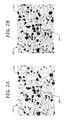
- FIG. 2A shows a plurality of embedded particles 210.
- the particles 210 are arranged in a pattern that is non-uniform and irregular.
- the particles 210 may be arranged in clumps.
- the particles 210 may be arranged in a stochastic pattern.
- the particles 210 may be arranged in a stochastic speckle pattern.
- the structure 110 may undergo stress from external forces and/or internal forces (e.g., by temperature cycling).
- the stress causes strain in the structure 110.
- the strain may cause deformations or internal inconsistencies such as voids, wrinkles, cracks and delaminations.
- FIG. 3 illustrates a method of determining strains within a structure having particles embedded particles therein, where the particles are not completely transparent to X-rays.
- the structure is illuminated with X-rays. Except for the particles, the structure may fully transmit the X-rays. The particles prevent the X-rays from being fully transmitted. For instance, the particles may fluoresce, scatter or absorb the X-rays, or they may reflect the X-rays (e.g., at grazing incidence).
- an image of the illuminated structure is formed.
- the image shows a pattern of particles at a level within the structure.
- the image is processed to determine displacements of the particles at different locations at the level.
- strains are computed from the displacements.
- FIGS. 2A and 2B illustrate particles 210 embedded at a level within the structure 110.
- FIG. 2A is a baseline image of the particles 210 prior to the structure 110 undergoing stress
- FIG. 2B is an image of the particles after the structure 110 has undergone stress.
- a pixel block 220 encompasses several particles 210. Notice the skewing of the pixel block 220 in FIG. 2B . The skewing indicates that the particles 210 within the pixel block 220 have been displaced as a result of the stress.
- Displacements and strains may be computed by digital image correlation (DIC).
- DIC is an optical method that employs tracking and image registration techniques for accurate measurements of changes in images.
- DIC may perform pattern recognition on multiple images.
- Each image may be broken up into blocks of pixels (e.g., 15x15 pixel blocks, 25x25 pixel blocks 15x20 pixel blocks) that cover a certain number (e.g., five to seven) particles.
- These blocks of pixels are found in all of the images, and then the shape of each pixel block in each image is determined.
- the change of shape of each block of pixels determines a displacement at a location at the level. In this manner, displacements are determined at different locations at the level.
- a set of strains may then be computed at each block center.
- a strain field for the level may be formulated as a matrix of the strains.
- Interior modulus properties may also be determined from stress versus strain curves in the elastic region of the material.
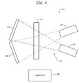
- FIG. 4 illustrates a system 410 for determining strains at a level within a structure 110, where particles are embedded at that level.
- the system 410 includes imaging apparatus 420 for capturing images of the particles within the structure 110.
- the imaging apparatus 420 of FIG. 4 includes first and second X-ray sources 422 and first and second X-ray detectors 424.
- the sources 422 may provide collimated X-rays. If the particles block the X-rays, the detectors may include semiconductor detectors that convert X-rays to electrical signals or semiconductor detectors that convert X-rays to visible light, which is then converted to electric signals. If the particles fluoresce in response to the X-rays, the image may be formed by energy dispersive detection.
- the first and second detectors 424 may be oriented at an angle with respect to the particles to create depth perception in the images. Depth perception, in turn, enables structural inconsistencies such as internal delaminations to be identified.
- a system herein is not limited to two detectors. Some embodiments may include only a single detector. Others may include more than two detectors.
- the system 410 further includes a computer 430 programmed to process the images created by the detectors 424.
- the processing includes digital image correlation of the pixel blocks of particles within the images.
- the computer 430 may be programmed with a commercial off the shelf DIC software, such as ARAMIS software.
- the computer 430 may be further programmed to identify internal structural inconsistencies from the strain field. For example, the strain field may be compared to baseline data corresponding to different types of structural inconsistencies. In other embodiments, skilled technicians may analyze the strain field to identify structural inconsistencies.
- FIG. 5 is an illustration of a method of using the system of FIG. 4 to perform nondestructive inspection on a structure having particles embedded at a level.
- the computer 430 accesses a baseline image of the structure.
- the baseline image represents a "healthy" structure.
- the baseline image may be been taken before the structure was placed into service, or it may be taken at a later time after having been stressed.
- the computer 430 commands the imaging apparatus 420 to capture one or more images of the particles within the structure 110.
- the computer 430 processes the captured and baseline images to detect displacement of a number of pixel blocks at each level. Several pixel blocks may be used to determine the value of displacement at a given location.
- the computer 430 determines strains from the pixel block displacements, and formulates a strain field at the level. If the structure 110 includes two parts bonded together at a bond line, and the particles are embedded in the bond line, then a strain field would be determined at the level of the bond line. If the structure 110 is a laminate, and one of the plies is embedded with particles, then a strain field would be determined at the level of that ply.
- the strain field is used to identify internal structural inconsistencies such as voids, wrinkles, delaminations and cracks. For example, a delamination would manifest as a change in out of plane displacement (in a 3D image), while a crack or wrinkle would manifest as a large localized strain.
- a structure herein is not limited to particles at a single level.
- a structure may include particles embedded at multiple levels.
- FIG. 6 is an illustration of a laminate 610 including metal particles embedded at multiple levels. Different types of particles are embedded in different plies. The type of particle may differ by nominal size and/or composition. As but one example, one ply 612 may be embedded with copper particles, another ply 614 may be embedded with titanium particles, another ply 616 with aluminum particles, and so on. Other metals include, but are not limited to, gold, silver, tungsten, and iron. Other plies 618 of the structure do not contain particles that affect the X-rays.
- FIG. 6 shows every other layer being imbedded with metal particles. In practice however, there may be greater separation between plies having embedded particles. As but one example, in a laminate having thirty plies, one of every six plies may contain metal particles.
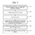
- FIG.7 illustrates the fabrication and nondestructive examination of a CFRP laminate.
- the different plies of the laminate Prior to layup, the different plies of the laminate are pre-impregnated with resins having different types of particles dispersed therein (block 710). Those plies not containing particles are impregnated with resin.
- the pre-impregnated plies may be deposited on a forming tool.
- nondestructive examination is performed.
- the laminate is illuminated with X-rays and the particles at different levels are imaged (block 740).
- the levels may be illuminated sequentially at different X-ray energy levels, thereby creating images of different levels.
- the different levels may be illuminated and imaged in a single pass. Particles at different levels may be differentiated by the amount of energy they absorb. For example, lead particles will absorb more energy than titanium particles and, consequently, will have a lower grayscale value in the image.
- the different particles absorb the X-rays and fluoresce at different frequencies. Images of the different levels may be formed by energy dispersive detection, which would allow discrimination of the florescent spectra of the different particles.
- the florescent spectra of titanium, copper, tungsten, and lead are dispersed at different levels.
- the displacement of the metal particles in the image is determined at different locations for each of the different levels (block 750). Strain fields are computed for the different levels (block 760).
Landscapes
- Health & Medical Sciences (AREA)
- Toxicology (AREA)
- Physics & Mathematics (AREA)
- Life Sciences & Earth Sciences (AREA)
- Chemical & Material Sciences (AREA)
- Analytical Chemistry (AREA)
- Biochemistry (AREA)
- General Health & Medical Sciences (AREA)
- General Physics & Mathematics (AREA)
- Immunology (AREA)
- Pathology (AREA)
- Analysing Materials By The Use Of Radiation (AREA)
Abstract
Description
- Nondestructive examination (NDE) may be used to evaluate properties of composite structures. For instance, NDE such as ultrasonic testing may reveal internal structural inconsistencies such as voids, wrinkles, cracks and delaminations.
- However, ultrasonic testing does not reveal internal strains within composite structures. Other techniques may determine strains at the surface or bulk of composite structures, but not within the composite structures.
- It would be desirable to nondestructively determine strains within composite structures.
- According to an embodiment herein, a system comprises a structure having particles embedded at a level within the structure, and X-ray imaging apparatus for capturing images of the particles at the level.
- According to another embodiment herein, a method of performing nondestructive examination on a structure having embedded particles comprises illuminating the structure with X-rays; forming an image of the illuminated structure, the image showing the particles; and determining displacements of the particles in the image.
- According to another embodiment herein, a laminate comprises a plurality of plies of reinforcing fibers in a matrix. The matrix contains patterns of metal particles embedded within different plies, wherein the particles embedded in the different plies differ by at least one of nominal size and composition.
- These features and functions may be achieved independently in various embodiments or may be combined in other embodiments. Further details of the embodiments can be seen with reference to the following description and drawings.
-
-
FIG. 1 is an illustration of a structure including embedded particles. -
FIGS. 2A and 2B are illustrations of particles embedded within a structure before and after the structure has undergone stress. -
FIG. 3 is an illustration of a method of determining strain within a structure having embedded particles. -
FIG. 4 is an illustration of a system for determining strain within a structure having embedded particles. -
FIG. 5 is an illustration of a method of using the system ofFIG. 4 . -
FIG. 6 is an illustration of a multi-ply structure including embedded particles at multiple levels. -
FIG.7 is an illustration of a method of fabricating and nondestructively examining a CFRP laminate. - Reference is made to
FIG. 1 , which illustrates astructure 110 including embedded particles. In some embodiments, thestructure 110 may be a composite laminate composed of a plurality of plies of reinforcing fibers embedded in a matrix. For instance, the laminate may include multiple plies of carbon reinforcing fibers embedded in a plastic matrix. InFIG. 1 , eachelement 112 represents multiple plies. In other embodiments, thestructure 110 may include two or more members 112 (e.g., rigid composite members) that are adhesively bonded together at a bond line. - The particles are embedded at a
level 114 below a surface of thestructure 110. As shown inFIG. 1 , thelevel 114 is at a depth (d) below the surface. For astructure 110 includingmembers 112 adhesively bonded together at a bond line, the particles may be embedded in the bond line. That is, the bond line is at a depth (d) below the surface. For astructure 110 including a plurality of laminatedplies 112, the particles may be embedded in one or more of the plies. That is, the ply or plies containing the embedded particles are a depth (d) below the surface. - The embedded particles are made of a material that is not completely transparent to X-rays. For instance, the embedded particles may fluoresce, scatter or absorb X-rays. In some embodiments, the particles may be metal particles. The particles may be micron-sized or smaller.
- Reference is now made to
FIG. 2A , which shows a plurality of embeddedparticles 210. Theparticles 210 are arranged in a pattern that is non-uniform and irregular. In some embodiments, theparticles 210 may be arranged in clumps. In other embodiments, theparticles 210 may be arranged in a stochastic pattern. For example, theparticles 210 may be arranged in a stochastic speckle pattern. - The
structure 110 may undergo stress from external forces and/or internal forces (e.g., by temperature cycling). The stress causes strain in thestructure 110. In laminates made of composite fiber reinforced plastic (CFRP), for instance, the strain may cause deformations or internal inconsistencies such as voids, wrinkles, cracks and delaminations. - Reference is now made to
FIG. 3 , which illustrates a method of determining strains within a structure having particles embedded particles therein, where the particles are not completely transparent to X-rays. Atblock 310, the structure is illuminated with X-rays. Except for the particles, the structure may fully transmit the X-rays. The particles prevent the X-rays from being fully transmitted. For instance, the particles may fluoresce, scatter or absorb the X-rays, or they may reflect the X-rays (e.g., at grazing incidence). - At
block 320, an image of the illuminated structure is formed. The image shows a pattern of particles at a level within the structure. - At
block 330, the image is processed to determine displacements of the particles at different locations at the level. Atblock 340, strains are computed from the displacements. - Reference is made to
FIGS. 2A and 2B , which illustrateparticles 210 embedded at a level within thestructure 110. AssumeFIG. 2A is a baseline image of theparticles 210 prior to thestructure 110 undergoing stress, and assumeFIG. 2B is an image of the particles after thestructure 110 has undergone stress. Apixel block 220 encompassesseveral particles 210. Notice the skewing of thepixel block 220 inFIG. 2B . The skewing indicates that theparticles 210 within thepixel block 220 have been displaced as a result of the stress. - Displacements and strains may be computed by digital image correlation (DIC). DIC is an optical method that employs tracking and image registration techniques for accurate measurements of changes in images. DIC may perform pattern recognition on multiple images. Each image may be broken up into blocks of pixels (e.g., 15x15 pixel blocks, 25x25 pixel blocks 15x20 pixel blocks) that cover a certain number (e.g., five to seven) particles. These blocks of pixels are found in all of the images, and then the shape of each pixel block in each image is determined. The change of shape of each block of pixels determines a displacement at a location at the level. In this manner, displacements are determined at different locations at the level.
- A set of strains may then be computed at each block center. A strain field for the level may be formulated as a matrix of the strains. Interior modulus properties may also be determined from stress versus strain curves in the elastic region of the material.
- Reference is now made to
FIG. 4 , which illustrates asystem 410 for determining strains at a level within astructure 110, where particles are embedded at that level. Thesystem 410 includesimaging apparatus 420 for capturing images of the particles within thestructure 110. Theimaging apparatus 420 ofFIG. 4 includes first andsecond X-ray sources 422 and first andsecond X-ray detectors 424. Thesources 422 may provide collimated X-rays. If the particles block the X-rays, the detectors may include semiconductor detectors that convert X-rays to electrical signals or semiconductor detectors that convert X-rays to visible light, which is then converted to electric signals. If the particles fluoresce in response to the X-rays, the image may be formed by energy dispersive detection. - High contrast in the images is desirable. Distances between the
sources 422, thestructure 110, and thedetectors 424 may be adjusted to give the proper field of view and best contrast. - The first and
second detectors 424 may be oriented at an angle with respect to the particles to create depth perception in the images. Depth perception, in turn, enables structural inconsistencies such as internal delaminations to be identified. - A system herein is not limited to two detectors. Some embodiments may include only a single detector. Others may include more than two detectors.
- The
system 410 further includes acomputer 430 programmed to process the images created by thedetectors 424. The processing includes digital image correlation of the pixel blocks of particles within the images. Thecomputer 430 may be programmed with a commercial off the shelf DIC software, such as ARAMIS software. - In some embodiments, the
computer 430 may be further programmed to identify internal structural inconsistencies from the strain field. For example, the strain field may be compared to baseline data corresponding to different types of structural inconsistencies. In other embodiments, skilled technicians may analyze the strain field to identify structural inconsistencies. -
FIG. 5 is an illustration of a method of using the system ofFIG. 4 to perform nondestructive inspection on a structure having particles embedded at a level. Atblock 510, thecomputer 430 accesses a baseline image of the structure. The baseline image represents a "healthy" structure. The baseline image may be been taken before the structure was placed into service, or it may be taken at a later time after having been stressed. - At block 520, the
computer 430 commands theimaging apparatus 420 to capture one or more images of the particles within thestructure 110. - At
block 530, thecomputer 430 processes the captured and baseline images to detect displacement of a number of pixel blocks at each level. Several pixel blocks may be used to determine the value of displacement at a given location. - At
block 540, thecomputer 430 determines strains from the pixel block displacements, and formulates a strain field at the level. If thestructure 110 includes two parts bonded together at a bond line, and the particles are embedded in the bond line, then a strain field would be determined at the level of the bond line. If thestructure 110 is a laminate, and one of the plies is embedded with particles, then a strain field would be determined at the level of that ply. - At
block 550, the strain field is used to identify internal structural inconsistencies such as voids, wrinkles, delaminations and cracks. For example, a delamination would manifest as a change in out of plane displacement (in a 3D image), while a crack or wrinkle would manifest as a large localized strain. - A structure herein is not limited to particles at a single level. In some embodiments, a structure may include particles embedded at multiple levels.
-
FIG. 6 is an illustration of a laminate 610 including metal particles embedded at multiple levels. Different types of particles are embedded in different plies. The type of particle may differ by nominal size and/or composition. As but one example, oneply 612 may be embedded with copper particles, anotherply 614 may be embedded with titanium particles, anotherply 616 with aluminum particles, and so on. Other metals include, but are not limited to, gold, silver, tungsten, and iron.Other plies 618 of the structure do not contain particles that affect the X-rays. -
FIG. 6 shows every other layer being imbedded with metal particles. In practice however, there may be greater separation between plies having embedded particles. As but one example, in a laminate having thirty plies, one of every six plies may contain metal particles. - Reference is now made to
FIG.7 , which illustrates the fabrication and nondestructive examination of a CFRP laminate. Prior to layup, the different plies of the laminate are pre-impregnated with resins having different types of particles dispersed therein (block 710). Those plies not containing particles are impregnated with resin. During layup of the laminate (block 720), the pre-impregnated plies may be deposited on a forming tool. - After the layup has been cured (block 730), nondestructive examination is performed. During nondestructive examination, the laminate is illuminated with X-rays and the particles at different levels are imaged (block 740). In some embodiments, the levels may be illuminated sequentially at different X-ray energy levels, thereby creating images of different levels. In other embodiments, the different levels may be illuminated and imaged in a single pass. Particles at different levels may be differentiated by the amount of energy they absorb. For example, lead particles will absorb more energy than titanium particles and, consequently, will have a lower grayscale value in the image.
- In other embodiments, the different particles absorb the X-rays and fluoresce at different frequencies. Images of the different levels may be formed by energy dispersive detection, which would allow discrimination of the florescent spectra of the different particles. For example, the florescent spectra of titanium, copper, tungsten, and lead are dispersed at different levels.
- Using DIC, the displacement of the metal particles in the image is determined at different locations for each of the different levels (block 750). Strain fields are computed for the different levels (block 760).
Claims (16)
- A system comprising
a structure (110) having particles (210) embedded at a level (114) within the structure (110); and
X-ray imaging apparatus (420) for capturing images of the particles (210) at the level (114). - The system of claim 1, further comprising a computer programmed to analyze the images to determine (340) strains at different locations at the level.
- The system of claim 2, further comprising identifying (550) internal structural inconsistencies from the strains; and
wherein determining the strains includes forming pixel blocks (220) containing the particles (210), and determining (530) changes in shape of the pixel blocks (220); and
wherein the computer (430) is programmed to perform digital image correlation of the particles (210) in the images. - The system of claim 1, wherein the imaging apparatus includes first and second X-ray sources (320) on one side of the structure (110) and at least one X-ray detector on an opposite side of the structure (110).
- The system of claim 1, wherein the particles (210) are arranged in a non-uniform, irregular pattern; and
wherein the particles (210) are metal particles. - The system of claim 1, wherein the structure (110) includes first and second members (112) joined by a layer of adhesive, the adhesive layer containing a pattern of the particles (210).
- The system of claim 1, wherein the structure (110) includes a laminate (112) and wherein the particles (210) are embedded in at least one of plies (612, 614, 616) of the laminate (112).
- The system of claim 1, wherein the structure (110) includes plies (612, 614, 616) of reinforcing fibers embedded in a matrix; and wherein different types of the particles (210) are embedded in different plies (612, 614, 616) within the structure (110).
- A method of performing nondestructive examination on a structure (110) having embedded particles (210), the particles embedded at a level (114) within the structure (110), the method comprising:illuminating (310) the structure (110) with X-rays;forming (320) an image of the illuminated structure (110), the image showing the particles (740); anddetermining (330) displacements of the particles in the image (750).
- The method of claim 9, wherein the particles (210) are illuminated to fluoresce, scatter, or absorb the X-rays (740).
- The method of claim 9, wherein determining (330) the displacements includes determining (530) shape changes of pixel blocks (220) in the image; and determining strains from the displacements (340).
- The method of claim 9, wherein a computer (430) is used to perform digital image correlation (DIC) to determine (330) the displacement of the particles (210).
- The method of claim 9, wherein forming (320) the image includes using first and second detectors (424) at an angle with respect to the particles (210) to create depth in the image.
- The method of claim 9, wherein the particles (210) are embedded in multiple plies (612, 614, 616), wherein the particles (210) embedded in the plies (612, 614, 616) differ by a nominal size and/or composition;
wherein the plies (612, 614, 616) having embedded particles (210) are illuminated (740) at different X-ray energy levels; and
wherein the displacement of the particles (210) in the image is determined (750) for each ply (612, 614, 616) having embedded particles (210). - The method of claim 9, wherein the particles (210) are embedded in different plies (612, 614, 616), wherein the particles (210) embedded in the different plies (612, 614, 616) differ by a nominal size and/or composition; wherein the different plies (612, 614, 616) having embedded particles (210) are illuminated (740) to fluoresce, and wherein forming (320) the image includes using energy dispersive detection to image the fluorescing particles (210).
- A laminate (110, 610) comprising a plurality of plies (612, 614, 616, 618) of reinforcing fibers in a matrix, the matrix containing patterns of metal particles (210) embedded within different plies (612, 614, 616), wherein the particles (210) embedded in the different plies (612, 614, 616) differ by at least one of nominal size and composition.
Applications Claiming Priority (1)
| Application Number | Priority Date | Filing Date | Title |
|---|---|---|---|
| US13/647,423 US9042516B2 (en) | 2012-10-09 | 2012-10-09 | Nondestructive examination of structures having embedded particles |
Publications (3)
| Publication Number | Publication Date |
|---|---|
| EP2720031A2 true EP2720031A2 (en) | 2014-04-16 |
| EP2720031A3 EP2720031A3 (en) | 2014-06-25 |
| EP2720031B1 EP2720031B1 (en) | 2016-12-07 |
Family
ID=49354440
Family Applications (1)
| Application Number | Title | Priority Date | Filing Date |
|---|---|---|---|
| EP13187024.8A Active EP2720031B1 (en) | 2012-10-09 | 2013-10-02 | Nondestructive examination of structures having embedded particles |
Country Status (7)
| Country | Link |
|---|---|
| US (1) | US9042516B2 (en) |
| EP (1) | EP2720031B1 (en) |
| JP (1) | JP6280339B2 (en) |
| CN (1) | CN103712998B (en) |
| BR (1) | BR102013026020B1 (en) |
| CA (1) | CA2823296C (en) |
| RU (1) | RU2632579C2 (en) |
Cited By (2)
| Publication number | Priority date | Publication date | Assignee | Title |
|---|---|---|---|---|
| EP3279607A1 (en) * | 2016-08-05 | 2018-02-07 | General Electric Company | Embedded strain sensor network |
| WO2023281101A1 (en) * | 2021-07-09 | 2023-01-12 | Universite Toulouse Iii - Paul Sabatier | Method for generating a map representing mechanically altered areas of an adhesive within a bonded assembly of composite materials, corresponding device and computer program |
Families Citing this family (19)
| Publication number | Priority date | Publication date | Assignee | Title |
|---|---|---|---|---|
| US9443300B2 (en) | 2014-09-15 | 2016-09-13 | The Boeing Company | Systems and methods for analyzing a bondline |
| US11354881B2 (en) | 2015-07-27 | 2022-06-07 | United Launch Alliance, L.L.C. | System and method to enable the application of optical tracking techniques for generating dynamic quantities of interest with alias protection |
| DE102015216015A1 (en) * | 2015-08-21 | 2017-02-23 | Bayerische Motoren Werke Aktiengesellschaft | Component, method for manufacturing and method for testing a component made of a fiber composite material |
| US9939393B2 (en) * | 2015-09-28 | 2018-04-10 | United Technologies Corporation | Detection of crystallographic properties in aerospace components |
| US10801836B2 (en) | 2017-06-13 | 2020-10-13 | The Boeing Company | Composite parts that facilitate ultrasonic imaging of layer boundaries |
| JP6909137B2 (en) * | 2017-11-30 | 2021-07-28 | Toyo Tire株式会社 | Contact state analysis method for rubber materials |
| JP7027139B2 (en) * | 2017-11-30 | 2022-03-01 | Toyo Tire株式会社 | How to analyze the tearing behavior of rubber materials |
| US12007220B2 (en) * | 2017-12-29 | 2024-06-11 | II John Tyson | Optical structural health monitoring |
| US11486697B1 (en) * | 2017-12-29 | 2022-11-01 | II John Tyson | Optical structural health monitoring |
| CN108444629B (en) * | 2018-03-05 | 2020-08-28 | 中国商用飞机有限责任公司北京民用飞机技术研究中心 | A nail load measurement method, device, measuring instrument and storage medium |
| US11276159B1 (en) | 2018-05-15 | 2022-03-15 | United Launch Alliance, L.L.C. | System and method for rocket engine health monitoring using digital image correlation (DIC) |
| CN109884091A (en) * | 2019-03-08 | 2019-06-14 | 北京理工大学 | A kind of rapid testing technology for lithium ion battery structure internal modification field |
| GB202000156D0 (en) * | 2020-01-07 | 2020-02-19 | Adaptix Ltd | A composite material |
| CN114152212A (en) * | 2020-08-18 | 2022-03-08 | 索尼集团公司 | Electronic device and method |
| JP7571624B2 (en) * | 2021-03-04 | 2024-10-23 | 住友ゴム工業株式会社 | Method and device for evaluating performance of elastic material |
| JP7800278B2 (en) * | 2022-04-18 | 2026-01-16 | 住友ゴム工業株式会社 | Performance evaluation method for elastic materials |
| GB2623809A (en) * | 2022-10-28 | 2024-05-01 | Adaptix Ltd | A system and method of producing a tomogram |
| US20240159689A1 (en) * | 2022-11-02 | 2024-05-16 | National Technology & Engineering Solutions Of Sandia, Llc | Path-integrated x-ray images for digital image correlation |
| WO2025088790A1 (en) * | 2023-10-27 | 2025-05-01 | 株式会社ニコン | Inspection system, display device, inspection method, program, method for manufacturing laminate, and control device |
Family Cites Families (32)
| Publication number | Priority date | Publication date | Assignee | Title |
|---|---|---|---|---|
| US3412243A (en) | 1965-01-25 | 1968-11-19 | Navy Usa | X-ray apparatus for measuring internal strains in an elastomeric body having spaced particles embedded therein |
| US3956631A (en) | 1974-06-20 | 1976-05-11 | Rca Corporation | Process for non-destructive inspection |
| JPS5612540A (en) * | 1979-07-13 | 1981-02-06 | Hitachi Ltd | Plastics processing strain analysis by model |
| IT1143266B (en) * | 1981-01-14 | 1986-10-22 | Agusta Aeronaut Costr | METHOD FOR PERFORMING NON-DESTRUCTIVE TESTS ON COMPONENTS OF COMPOSITE MATERIALS |
| US5641422A (en) | 1991-04-05 | 1997-06-24 | The Boeing Company | Thermoplastic welding of organic resin composites using a fixed coil induction heater |
| JP3313165B2 (en) | 1992-11-24 | 2002-08-12 | 本田技研工業株式会社 | Method of bonding fiber-reinforced plastic member and method of detecting defective bonding of fiber-reinforced plastic member containing adhesive layer |
| US6127822A (en) | 1994-01-26 | 2000-10-03 | Honda Giken Kogyo Kabushiki Kaisha | Adhesive member for forming an adhesive layer between two members and capable of detecting an internal defect in the adhesive layer |
| US5483571A (en) | 1994-05-31 | 1996-01-09 | The United States Of America As Represented By The Administrator Of The National Aeronautics And Space Administration | Radiographic moire |
| US5833795A (en) | 1996-09-19 | 1998-11-10 | Mcdonnell Douglas Corporation | Magnetic particle integrated adhesive and associated method of repairing a composite material product |
| JP2971432B2 (en) * | 1998-03-13 | 1999-11-08 | 川崎重工業株式会社 | Inspection method of fiber reinforced plastic structure |
| JPH11258186A (en) * | 1998-03-16 | 1999-09-24 | Kansai Shingijutsu Kenkyusho:Kk | Method and apparatus for measuring stress by X-ray |
| JP2000213999A (en) * | 1999-01-22 | 2000-08-04 | Rigaku Corp | X-ray stress measurement method |
| RU2168717C1 (en) * | 2000-11-23 | 2001-06-10 | Горшков Вячеслав Алексеевич | Technology of tomographic evaluation of distribution of density and effective atomic number of substance |
| JP3487292B2 (en) * | 2001-02-09 | 2004-01-13 | 株式会社島津製作所 | X-ray fluoroscope |
| DE10322055A1 (en) | 2003-05-15 | 2004-12-02 | Sustech Gmbh & Co. Kg | Joining metallic and non-metallic components with hot-melt adhesive uses press mold with groove containing microwave conductor along seam |
| US20050282300A1 (en) * | 2002-05-29 | 2005-12-22 | Xradia, Inc. | Back-end-of-line metallization inspection and metrology microscopy system and method using x-ray fluorescence |
| US6849195B2 (en) | 2003-04-03 | 2005-02-01 | Delphi Technologies, Inc. | Composites with large magnetostriction |
| WO2005005479A1 (en) * | 2003-05-09 | 2005-01-20 | University Of Massachusetts | Non-human animals expressing heterologous complement receptor type 1 (cr1) molecules on erythrocytes and uses therefor |
| WO2005031329A1 (en) * | 2003-08-04 | 2005-04-07 | X-Ray Optical Systems, Inc. | In-situ x-ray diffraction system using sources and detectors at fixed angular positions |
| EP1619495A1 (en) * | 2004-07-23 | 2006-01-25 | Nederlandse Organisatie voor toegepast-natuurwetenschappelijk Onderzoek TNO | Method and Apparatus for inspecting a specimen surface and use of fluorescent materials |
| US20060214115A1 (en) * | 2005-03-23 | 2006-09-28 | General Electric Company | Phosphor film, imaging assembly and inspection method |
| US20100012004A1 (en) * | 2005-06-01 | 2010-01-21 | U.S. Wind Farming Inc. | Basalt particle-containing compositions and articles for protective coatings and ballistic shield mats/tiles/protective building components |
| DE202005017496U1 (en) * | 2005-11-07 | 2007-03-15 | Comet Gmbh | Target for a microfocus or nanofocus X-ray tube |
| US8220991B2 (en) * | 2006-05-12 | 2012-07-17 | The Boeing Company | Electromagnetically heating a conductive medium in a composite aircraft component |
| FR2907706B1 (en) * | 2006-10-26 | 2009-02-06 | Snecma Sa | PROCESS FOR MANUFACTURING A WINDOW WINDOW IN COMPOSITE MATERIAL |
| US20080145647A1 (en) * | 2006-12-13 | 2008-06-19 | Rahul Ganguli | Metal impregnated composites and methods of making |
| GB0717507D0 (en) * | 2007-09-07 | 2007-10-17 | Cytec Tech Corp | Composite materials and their use |
| US20090184261A1 (en) | 2008-01-21 | 2009-07-23 | Moshe Ein-Gal | Imaging with a plurality of sources to a common detector |
| WO2009107575A1 (en) * | 2008-02-25 | 2009-09-03 | 大学共同利用機関法人高エネルギー加速器研究機構 | Device for nondestructively examining composite structure and nondestructive examination method |
| US8397580B2 (en) * | 2010-09-16 | 2013-03-19 | The Boeing Company | Multi-ferroic structural health monitoring systems and methods |
| US8641845B2 (en) | 2011-01-13 | 2014-02-04 | Siemens Energy, Inc. | Method of determining bond coverage in a joint |
| JP2012168075A (en) * | 2011-02-16 | 2012-09-06 | Niigata Univ | Method for measurement of internal stress of material including large grain |
-
2012
- 2012-10-09 US US13/647,423 patent/US9042516B2/en active Active
-
2013
- 2013-08-08 CA CA2823296A patent/CA2823296C/en active Active
- 2013-09-30 CN CN201310460160.XA patent/CN103712998B/en active Active
- 2013-10-02 EP EP13187024.8A patent/EP2720031B1/en active Active
- 2013-10-08 JP JP2013211209A patent/JP6280339B2/en active Active
- 2013-10-08 RU RU2013144945A patent/RU2632579C2/en active
- 2013-10-09 BR BR102013026020-7A patent/BR102013026020B1/en active IP Right Grant
Non-Patent Citations (1)
| Title |
|---|
| None |
Cited By (3)
| Publication number | Priority date | Publication date | Assignee | Title |
|---|---|---|---|---|
| EP3279607A1 (en) * | 2016-08-05 | 2018-02-07 | General Electric Company | Embedded strain sensor network |
| WO2023281101A1 (en) * | 2021-07-09 | 2023-01-12 | Universite Toulouse Iii - Paul Sabatier | Method for generating a map representing mechanically altered areas of an adhesive within a bonded assembly of composite materials, corresponding device and computer program |
| FR3125127A1 (en) * | 2021-07-09 | 2023-01-13 | Universite Toulouse Iii - Paul Sabatier | Method for generating a map representative of mechanically altered areas of an adhesive within a bonded assembly of composite materials, corresponding device and computer program |
Also Published As
| Publication number | Publication date |
|---|---|
| RU2632579C2 (en) | 2017-10-06 |
| CA2823296C (en) | 2015-12-22 |
| RU2013144945A (en) | 2015-04-20 |
| JP6280339B2 (en) | 2018-02-14 |
| JP2014077790A (en) | 2014-05-01 |
| CA2823296A1 (en) | 2014-04-09 |
| BR102013026020A2 (en) | 2014-10-29 |
| EP2720031A3 (en) | 2014-06-25 |
| EP2720031B1 (en) | 2016-12-07 |
| US9042516B2 (en) | 2015-05-26 |
| CN103712998A (en) | 2014-04-09 |
| US20140098936A1 (en) | 2014-04-10 |
| BR102013026020B1 (en) | 2020-12-22 |
| CN103712998B (en) | 2017-11-17 |
Similar Documents
| Publication | Publication Date | Title |
|---|---|---|
| US9042516B2 (en) | Nondestructive examination of structures having embedded particles | |
| Léonard et al. | The quantification of impact damage distribution in composite laminates by analysis of X-ray computed tomograms | |
| JP7358648B2 (en) | Molded body area inspection program, molded body area inspection method, molded body area inspection device | |
| Oz et al. | Damage mode identification in transverse crack tension specimens using acoustic emission and correlation with finite element progressive damage model | |
| da Silva | Image processing methodology for assessment of drilling induced damage in CFRP | |
| WO2021140312A1 (en) | A method of producing 3d tomosynthesis images of a composite material | |
| CN112179925A (en) | Three-dimensional nondestructive testing method for impact damage of composite material laminated plate | |
| Diemar et al. | X-ray micro-computed tomography for mechanical behaviour analysis of Automated Fiber Placement (AFP) laminates with integrated gaps and overlaps | |
| Caminero et al. | Using digital image correlation techniques for damage detection on adhesively bonded composite repairs | |
| CN110794037A (en) | Quantitative evaluation method for drilling defects of carbon fiber composite material | |
| Léonard et al. | Impact damage characterisation of fibre metal laminates by X-ray computed tomography | |
| CA3134851C (en) | Strength evaluation device and strength evaluation method | |
| JP2971432B2 (en) | Inspection method of fiber reinforced plastic structure | |
| EP3351928B1 (en) | X-ray sidescatter inspection of laminates | |
| Wang et al. | Non-destructive damage evaluation of composites based on X-ray and ultrasonic image fusion | |
| Demerath | Low velocity impact damage assessment in IM7/977-3 cross-ply composites using 3D computed tomography | |
| Liu et al. | Applicability of a new composite amusement ride safety device based on acoustic emission monitoring technology | |
| Tu et al. | Experimental Investigation of Planar Delamination Behaviour of Composite Laminates Under Out-Of-Plane Loading | |
| Ferreira et al. | MicroCT-based methodology for defect detection and analysis in GRFP tube Joints | |
| Makeev et al. | Manufacturing issues and measurement techniques for assessment of the effects on structural performance of composite parts | |
| Guinn | 2D Digital Image Correlation of Barely Visible Impact Damage of T300 Carbon Fiber-Reinforced Polymer and Residual Compressive Strength Testing | |
| JP7717841B2 (en) | Inspection program for molded body area, inspection method for molded body area, inspection device for molded body area, and recording medium | |
| Sitek et al. | Analysis of drilling process of composite structures, part II: quality control of drilled holes | |
| Oz et al. | In-situ damage monitoring and correlation with Acoustic Emission in CFRP composites | |
| Barsanescu et al. | Finite Elements Analysis of CFRP Specimens with Included Cracks |
Legal Events
| Date | Code | Title | Description |
|---|---|---|---|
| PUAI | Public reference made under article 153(3) epc to a published international application that has entered the european phase |
Free format text: ORIGINAL CODE: 0009012 |
|
| 17P | Request for examination filed |
Effective date: 20131002 |
|
| AK | Designated contracting states |
Kind code of ref document: A2 Designated state(s): AL AT BE BG CH CY CZ DE DK EE ES FI FR GB GR HR HU IE IS IT LI LT LU LV MC MK MT NL NO PL PT RO RS SE SI SK SM TR |
|
| AX | Request for extension of the european patent |
Extension state: BA ME |
|
| PUAL | Search report despatched |
Free format text: ORIGINAL CODE: 0009013 |
|
| AK | Designated contracting states |
Kind code of ref document: A3 Designated state(s): AL AT BE BG CH CY CZ DE DK EE ES FI FR GB GR HR HU IE IS IT LI LT LU LV MC MK MT NL NO PL PT RO RS SE SI SK SM TR |
|
| AX | Request for extension of the european patent |
Extension state: BA ME |
|
| RIC1 | Information provided on ipc code assigned before grant |
Ipc: G01N 23/223 20060101ALI20140520BHEP Ipc: G01N 23/083 20060101ALI20140520BHEP Ipc: G01N 23/04 20060101ALI20140520BHEP Ipc: G01N 23/18 20060101ALI20140520BHEP Ipc: G01N 23/087 20060101AFI20140520BHEP |
|
| 17Q | First examination report despatched |
Effective date: 20150507 |
|
| GRAP | Despatch of communication of intention to grant a patent |
Free format text: ORIGINAL CODE: EPIDOSNIGR1 |
|
| INTG | Intention to grant announced |
Effective date: 20160513 |
|
| GRAS | Grant fee paid |
Free format text: ORIGINAL CODE: EPIDOSNIGR3 |
|
| GRAA | (expected) grant |
Free format text: ORIGINAL CODE: 0009210 |
|
| AK | Designated contracting states |
Kind code of ref document: B1 Designated state(s): AL AT BE BG CH CY CZ DE DK EE ES FI FR GB GR HR HU IE IS IT LI LT LU LV MC MK MT NL NO PL PT RO RS SE SI SK SM TR |
|
| REG | Reference to a national code |
Ref country code: GB Ref legal event code: FG4D |
|
| REG | Reference to a national code |
Ref country code: CH Ref legal event code: EP Ref country code: AT Ref legal event code: REF Ref document number: 852185 Country of ref document: AT Kind code of ref document: T Effective date: 20161215 |
|
| REG | Reference to a national code |
Ref country code: IE Ref legal event code: FG4D |
|
| REG | Reference to a national code |
Ref country code: DE Ref legal event code: R096 Ref document number: 602013014958 Country of ref document: DE |
|
| PG25 | Lapsed in a contracting state [announced via postgrant information from national office to epo] |
Ref country code: LV Free format text: LAPSE BECAUSE OF FAILURE TO SUBMIT A TRANSLATION OF THE DESCRIPTION OR TO PAY THE FEE WITHIN THE PRESCRIBED TIME-LIMIT Effective date: 20161207 |
|
| REG | Reference to a national code |
Ref country code: LT Ref legal event code: MG4D |
|
| REG | Reference to a national code |
Ref country code: NL Ref legal event code: MP Effective date: 20161207 |
|
| PG25 | Lapsed in a contracting state [announced via postgrant information from national office to epo] |
Ref country code: LT Free format text: LAPSE BECAUSE OF FAILURE TO SUBMIT A TRANSLATION OF THE DESCRIPTION OR TO PAY THE FEE WITHIN THE PRESCRIBED TIME-LIMIT Effective date: 20161207 Ref country code: GR Free format text: LAPSE BECAUSE OF FAILURE TO SUBMIT A TRANSLATION OF THE DESCRIPTION OR TO PAY THE FEE WITHIN THE PRESCRIBED TIME-LIMIT Effective date: 20170308 Ref country code: NO Free format text: LAPSE BECAUSE OF FAILURE TO SUBMIT A TRANSLATION OF THE DESCRIPTION OR TO PAY THE FEE WITHIN THE PRESCRIBED TIME-LIMIT Effective date: 20170307 Ref country code: SE Free format text: LAPSE BECAUSE OF FAILURE TO SUBMIT A TRANSLATION OF THE DESCRIPTION OR TO PAY THE FEE WITHIN THE PRESCRIBED TIME-LIMIT Effective date: 20161207 |
|
| REG | Reference to a national code |
Ref country code: AT Ref legal event code: MK05 Ref document number: 852185 Country of ref document: AT Kind code of ref document: T Effective date: 20161207 |
|
| PG25 | Lapsed in a contracting state [announced via postgrant information from national office to epo] |
Ref country code: ES Free format text: LAPSE BECAUSE OF FAILURE TO SUBMIT A TRANSLATION OF THE DESCRIPTION OR TO PAY THE FEE WITHIN THE PRESCRIBED TIME-LIMIT Effective date: 20161207 Ref country code: RS Free format text: LAPSE BECAUSE OF FAILURE TO SUBMIT A TRANSLATION OF THE DESCRIPTION OR TO PAY THE FEE WITHIN THE PRESCRIBED TIME-LIMIT Effective date: 20161207 Ref country code: HR Free format text: LAPSE BECAUSE OF FAILURE TO SUBMIT A TRANSLATION OF THE DESCRIPTION OR TO PAY THE FEE WITHIN THE PRESCRIBED TIME-LIMIT Effective date: 20161207 Ref country code: FI Free format text: LAPSE BECAUSE OF FAILURE TO SUBMIT A TRANSLATION OF THE DESCRIPTION OR TO PAY THE FEE WITHIN THE PRESCRIBED TIME-LIMIT Effective date: 20161207 |
|
| PG25 | Lapsed in a contracting state [announced via postgrant information from national office to epo] |
Ref country code: NL Free format text: LAPSE BECAUSE OF FAILURE TO SUBMIT A TRANSLATION OF THE DESCRIPTION OR TO PAY THE FEE WITHIN THE PRESCRIBED TIME-LIMIT Effective date: 20161207 |
|
| PG25 | Lapsed in a contracting state [announced via postgrant information from national office to epo] |
Ref country code: SK Free format text: LAPSE BECAUSE OF FAILURE TO SUBMIT A TRANSLATION OF THE DESCRIPTION OR TO PAY THE FEE WITHIN THE PRESCRIBED TIME-LIMIT Effective date: 20161207 Ref country code: IS Free format text: LAPSE BECAUSE OF FAILURE TO SUBMIT A TRANSLATION OF THE DESCRIPTION OR TO PAY THE FEE WITHIN THE PRESCRIBED TIME-LIMIT Effective date: 20170407 Ref country code: EE Free format text: LAPSE BECAUSE OF FAILURE TO SUBMIT A TRANSLATION OF THE DESCRIPTION OR TO PAY THE FEE WITHIN THE PRESCRIBED TIME-LIMIT Effective date: 20161207 Ref country code: RO Free format text: LAPSE BECAUSE OF FAILURE TO SUBMIT A TRANSLATION OF THE DESCRIPTION OR TO PAY THE FEE WITHIN THE PRESCRIBED TIME-LIMIT Effective date: 20161207 Ref country code: CZ Free format text: LAPSE BECAUSE OF FAILURE TO SUBMIT A TRANSLATION OF THE DESCRIPTION OR TO PAY THE FEE WITHIN THE PRESCRIBED TIME-LIMIT Effective date: 20161207 |
|
| PG25 | Lapsed in a contracting state [announced via postgrant information from national office to epo] |
Ref country code: PL Free format text: LAPSE BECAUSE OF FAILURE TO SUBMIT A TRANSLATION OF THE DESCRIPTION OR TO PAY THE FEE WITHIN THE PRESCRIBED TIME-LIMIT Effective date: 20161207 Ref country code: AT Free format text: LAPSE BECAUSE OF FAILURE TO SUBMIT A TRANSLATION OF THE DESCRIPTION OR TO PAY THE FEE WITHIN THE PRESCRIBED TIME-LIMIT Effective date: 20161207 Ref country code: PT Free format text: LAPSE BECAUSE OF FAILURE TO SUBMIT A TRANSLATION OF THE DESCRIPTION OR TO PAY THE FEE WITHIN THE PRESCRIBED TIME-LIMIT Effective date: 20170407 Ref country code: SM Free format text: LAPSE BECAUSE OF FAILURE TO SUBMIT A TRANSLATION OF THE DESCRIPTION OR TO PAY THE FEE WITHIN THE PRESCRIBED TIME-LIMIT Effective date: 20161207 Ref country code: BG Free format text: LAPSE BECAUSE OF FAILURE TO SUBMIT A TRANSLATION OF THE DESCRIPTION OR TO PAY THE FEE WITHIN THE PRESCRIBED TIME-LIMIT Effective date: 20170307 Ref country code: IT Free format text: LAPSE BECAUSE OF FAILURE TO SUBMIT A TRANSLATION OF THE DESCRIPTION OR TO PAY THE FEE WITHIN THE PRESCRIBED TIME-LIMIT Effective date: 20161207 Ref country code: BE Free format text: LAPSE BECAUSE OF FAILURE TO SUBMIT A TRANSLATION OF THE DESCRIPTION OR TO PAY THE FEE WITHIN THE PRESCRIBED TIME-LIMIT Effective date: 20161207 |
|
| REG | Reference to a national code |
Ref country code: DE Ref legal event code: R097 Ref document number: 602013014958 Country of ref document: DE |
|
| PLBE | No opposition filed within time limit |
Free format text: ORIGINAL CODE: 0009261 |
|
| STAA | Information on the status of an ep patent application or granted ep patent |
Free format text: STATUS: NO OPPOSITION FILED WITHIN TIME LIMIT |
|
| REG | Reference to a national code |
Ref country code: FR Ref legal event code: PLFP Year of fee payment: 5 |
|
| 26N | No opposition filed |
Effective date: 20170908 |
|
| PG25 | Lapsed in a contracting state [announced via postgrant information from national office to epo] |
Ref country code: SI Free format text: LAPSE BECAUSE OF FAILURE TO SUBMIT A TRANSLATION OF THE DESCRIPTION OR TO PAY THE FEE WITHIN THE PRESCRIBED TIME-LIMIT Effective date: 20161207 Ref country code: DK Free format text: LAPSE BECAUSE OF FAILURE TO SUBMIT A TRANSLATION OF THE DESCRIPTION OR TO PAY THE FEE WITHIN THE PRESCRIBED TIME-LIMIT Effective date: 20161207 |
|
| PG25 | Lapsed in a contracting state [announced via postgrant information from national office to epo] |
Ref country code: MC Free format text: LAPSE BECAUSE OF FAILURE TO SUBMIT A TRANSLATION OF THE DESCRIPTION OR TO PAY THE FEE WITHIN THE PRESCRIBED TIME-LIMIT Effective date: 20161207 |
|
| REG | Reference to a national code |
Ref country code: CH Ref legal event code: PL |
|
| REG | Reference to a national code |
Ref country code: IE Ref legal event code: MM4A |
|
| PG25 | Lapsed in a contracting state [announced via postgrant information from national office to epo] |
Ref country code: LU Free format text: LAPSE BECAUSE OF NON-PAYMENT OF DUE FEES Effective date: 20171002 Ref country code: CH Free format text: LAPSE BECAUSE OF NON-PAYMENT OF DUE FEES Effective date: 20171031 Ref country code: LI Free format text: LAPSE BECAUSE OF NON-PAYMENT OF DUE FEES Effective date: 20171031 |
|
| PG25 | Lapsed in a contracting state [announced via postgrant information from national office to epo] |
Ref country code: MT Free format text: LAPSE BECAUSE OF NON-PAYMENT OF DUE FEES Effective date: 20171002 |
|
| REG | Reference to a national code |
Ref country code: FR Ref legal event code: PLFP Year of fee payment: 6 |
|
| PG25 | Lapsed in a contracting state [announced via postgrant information from national office to epo] |
Ref country code: IE Free format text: LAPSE BECAUSE OF NON-PAYMENT OF DUE FEES Effective date: 20171002 |
|
| PG25 | Lapsed in a contracting state [announced via postgrant information from national office to epo] |
Ref country code: HU Free format text: LAPSE BECAUSE OF FAILURE TO SUBMIT A TRANSLATION OF THE DESCRIPTION OR TO PAY THE FEE WITHIN THE PRESCRIBED TIME-LIMIT; INVALID AB INITIO Effective date: 20131002 |
|
| PG25 | Lapsed in a contracting state [announced via postgrant information from national office to epo] |
Ref country code: CY Free format text: LAPSE BECAUSE OF NON-PAYMENT OF DUE FEES Effective date: 20161207 |
|
| PG25 | Lapsed in a contracting state [announced via postgrant information from national office to epo] |
Ref country code: MK Free format text: LAPSE BECAUSE OF FAILURE TO SUBMIT A TRANSLATION OF THE DESCRIPTION OR TO PAY THE FEE WITHIN THE PRESCRIBED TIME-LIMIT Effective date: 20161207 |
|
| REG | Reference to a national code |
Ref country code: DE Ref legal event code: R082 Ref document number: 602013014958 Country of ref document: DE Representative=s name: MAIER, LL.M., MICHAEL C., DE Ref country code: DE Ref legal event code: R082 Ref document number: 602013014958 Country of ref document: DE Representative=s name: BOULT WADE TENNANT LLP, DE |
|
| REG | Reference to a national code |
Ref country code: DE Ref legal event code: R082 Ref document number: 602013014958 Country of ref document: DE Representative=s name: BOULT WADE TENNANT LLP, DE |
|
| PG25 | Lapsed in a contracting state [announced via postgrant information from national office to epo] |
Ref country code: TR Free format text: LAPSE BECAUSE OF FAILURE TO SUBMIT A TRANSLATION OF THE DESCRIPTION OR TO PAY THE FEE WITHIN THE PRESCRIBED TIME-LIMIT Effective date: 20161207 |
|
| PG25 | Lapsed in a contracting state [announced via postgrant information from national office to epo] |
Ref country code: AL Free format text: LAPSE BECAUSE OF FAILURE TO SUBMIT A TRANSLATION OF THE DESCRIPTION OR TO PAY THE FEE WITHIN THE PRESCRIBED TIME-LIMIT Effective date: 20161207 |
|
| P01 | Opt-out of the competence of the unified patent court (upc) registered |
Effective date: 20230516 |
|
| PGFP | Annual fee paid to national office [announced via postgrant information from national office to epo] |
Ref country code: DE Payment date: 20251029 Year of fee payment: 13 |
|
| PGFP | Annual fee paid to national office [announced via postgrant information from national office to epo] |
Ref country code: GB Payment date: 20251027 Year of fee payment: 13 |
|
| PGFP | Annual fee paid to national office [announced via postgrant information from national office to epo] |
Ref country code: FR Payment date: 20251027 Year of fee payment: 13 |