US9443300B2 - Systems and methods for analyzing a bondline - Google Patents
Systems and methods for analyzing a bondline Download PDFInfo
- Publication number
- US9443300B2 US9443300B2 US14/486,461 US201414486461A US9443300B2 US 9443300 B2 US9443300 B2 US 9443300B2 US 201414486461 A US201414486461 A US 201414486461A US 9443300 B2 US9443300 B2 US 9443300B2
- Authority
- US
- United States
- Prior art keywords
- internal image
- bondline
- computing device
- pattern
- loaded state
- Prior art date
- Legal status (The legal status is an assumption and is not a legal conclusion. Google has not performed a legal analysis and makes no representation as to the accuracy of the status listed.)
- Active, expires
Links
- 238000000034 method Methods 0.000 title claims abstract description 39
- 238000012423 maintenance Methods 0.000 claims abstract description 12
- 238000005457 optimization Methods 0.000 claims abstract description 5
- 238000003860 storage Methods 0.000 claims description 4
- 230000005670 electromagnetic radiation Effects 0.000 claims description 3
- 238000003384 imaging method Methods 0.000 description 24
- 230000008569 process Effects 0.000 description 9
- 239000000853 adhesive Substances 0.000 description 8
- 230000001070 adhesive effect Effects 0.000 description 8
- 238000010586 diagram Methods 0.000 description 8
- 239000000463 material Substances 0.000 description 8
- 238000002310 reflectometry Methods 0.000 description 7
- 239000002131 composite material Substances 0.000 description 4
- 238000006073 displacement reaction Methods 0.000 description 4
- 230000004044 response Effects 0.000 description 3
- 238000012360 testing method Methods 0.000 description 3
- 230000015556 catabolic process Effects 0.000 description 2
- 238000004891 communication Methods 0.000 description 2
- 230000002596 correlated effect Effects 0.000 description 2
- 238000006731 degradation reaction Methods 0.000 description 2
- 230000001066 destructive effect Effects 0.000 description 2
- 238000011156 evaluation Methods 0.000 description 2
- 238000005259 measurement Methods 0.000 description 2
- 238000012986 modification Methods 0.000 description 2
- 230000004048 modification Effects 0.000 description 2
- 238000012545 processing Methods 0.000 description 2
- 239000011347 resin Substances 0.000 description 2
- 229920005989 resin Polymers 0.000 description 2
- 230000009286 beneficial effect Effects 0.000 description 1
- 230000000875 corresponding effect Effects 0.000 description 1
- 230000000694 effects Effects 0.000 description 1
- 239000000835 fiber Substances 0.000 description 1
- 230000006870 function Effects 0.000 description 1
- 239000004973 liquid crystal related substance Substances 0.000 description 1
- 238000004519 manufacturing process Methods 0.000 description 1
- 229910052751 metal Inorganic materials 0.000 description 1
- 239000002184 metal Substances 0.000 description 1
- 238000010295 mobile communication Methods 0.000 description 1
- 239000002105 nanoparticle Substances 0.000 description 1
- 229910052755 nonmetal Inorganic materials 0.000 description 1
- 150000002843 nonmetals Chemical class 0.000 description 1
- 238000005507 spraying Methods 0.000 description 1
- 230000000007 visual effect Effects 0.000 description 1
Images


Classifications
-
- G—PHYSICS
- G06—COMPUTING; CALCULATING OR COUNTING
- G06T—IMAGE DATA PROCESSING OR GENERATION, IN GENERAL
- G06T7/00—Image analysis
- G06T7/0002—Inspection of images, e.g. flaw detection
- G06T7/0004—Industrial image inspection
- G06T7/001—Industrial image inspection using an image reference approach
-
- G—PHYSICS
- G06—COMPUTING; CALCULATING OR COUNTING
- G06F—ELECTRIC DIGITAL DATA PROCESSING
- G06F18/00—Pattern recognition
- G06F18/20—Analysing
- G06F18/22—Matching criteria, e.g. proximity measures
-
- G—PHYSICS
- G06—COMPUTING; CALCULATING OR COUNTING
- G06T—IMAGE DATA PROCESSING OR GENERATION, IN GENERAL
- G06T7/00—Image analysis
- G06T7/0002—Inspection of images, e.g. flaw detection
- G06T7/0004—Industrial image inspection
- G06T7/0008—Industrial image inspection checking presence/absence
-
- G—PHYSICS
- G06—COMPUTING; CALCULATING OR COUNTING
- G06V—IMAGE OR VIDEO RECOGNITION OR UNDERSTANDING
- G06V10/00—Arrangements for image or video recognition or understanding
- G06V10/70—Arrangements for image or video recognition or understanding using pattern recognition or machine learning
- G06V10/74—Image or video pattern matching; Proximity measures in feature spaces
- G06V10/75—Organisation of the matching processes, e.g. simultaneous or sequential comparisons of image or video features; Coarse-fine approaches, e.g. multi-scale approaches; using context analysis; Selection of dictionaries
-
- G—PHYSICS
- G06—COMPUTING; CALCULATING OR COUNTING
- G06V—IMAGE OR VIDEO RECOGNITION OR UNDERSTANDING
- G06V10/00—Arrangements for image or video recognition or understanding
- G06V10/98—Detection or correction of errors, e.g. by rescanning the pattern or by human intervention; Evaluation of the quality of the acquired patterns
- G06V10/993—Evaluation of the quality of the acquired pattern
-
- G—PHYSICS
- G06—COMPUTING; CALCULATING OR COUNTING
- G06T—IMAGE DATA PROCESSING OR GENERATION, IN GENERAL
- G06T2207/00—Indexing scheme for image analysis or image enhancement
- G06T2207/30—Subject of image; Context of image processing
- G06T2207/30108—Industrial image inspection
Definitions
- the present disclosure relates generally to analyzing composite/bonded structures by using hybrid non-destructive evaluation (NDE) and digital image correlation (DIC) techniques, and more specifically to analyzing properties of a bondline inside a structure, and predicting their life during service, thus, giving the owners a valuable tool for optimization of the maintenance effort and allowing them to make cost-optimal maintenance decisions.
- NDE non-destructive evaluation
- DIC digital image correlation
- At least some known systems for analyzing changes in a structure prior to and during loading involve applying random (visual) patterns to a surface of the structure, imaging the pattern prior to loading, imaging the pattern during loading, and correlating (i.e., comparing) images to determine an amount of deformation or displacement in the pattern.
- Such systems do not enable analysis of components or features that are not visible on the surface of the structure. Accordingly, hidden features, such as a bondline within a composite structure, cannot be analyzed using such techniques/systems.
- a method for analyzing a bondline in a structure is provided.
- the method is implemented by at least one computing device.
- the method includes obtaining, from a first side of the structure, by the at least one computing device, at least one first internal image of the structure that includes at least a first pattern associated with the bondline, wherein the structure is in a pre-loaded state.
- the method additionally includes obtaining, from the first side of the structure, by the at least one computing device, at least one second internal image of the structure that includes at least the first pattern, wherein the structure is in a loaded state.
- the method includes comparing, by the at least one computing device, the at least one first internal image with the at least one second internal image.
- the method includes determining, by the at least one computing device, at least one stress and/or strain-related property of the bondline based on the comparison. Additionally, the method includes predicting an estimated life of the bondline, whereby the estimated life provides a valuable tool for optimization of maintenance effort and enabling cost-optimal maintenance decisions.
- a computing device for use in analyzing a bondline in a structure.
- the computing device is configured to obtain, from a first side of the structure, at least one first internal image of the structure that includes at least a first pattern associated with the bondline, wherein the structure is in a pre-loaded state.
- the computing device is additionally configured to obtain, from the first side of the structure, at least one second internal image of the structure that includes at least the first pattern, wherein the structure is in a loaded state.
- the computing device is configured to compare the at least one first internal image with the at least one second internal image and determine at least one stress and/or strain-related property of the bondline based on the comparison.
- a computer-readable storage medium having computer-executable instructions embodied thereon for configuring a computing device to analyze a bondline in a structure.
- the computer-executable instructions When executed by the computing device, the computer-executable instructions cause the computing device to obtain, from a first side of the structure, at least one first internal image of the structure that includes at least a first pattern associated with the bondline, wherein the structure is in a pre-loaded state.
- the computer-executable instructions additionally cause the computing device to obtain, from the first side of the structure, at least one second internal image of the structure that includes at least the first pattern, wherein the structure is in a loaded state.
- the computer-executable instructions additionally cause the computing device to compare the at least one first internal image with the at least one second internal image and determine at least one stress and/or strain-related property of the bondline based on the comparison.
- FIG. 1 is a diagram of an example environment in which an analysis computing device coupled to an imaging device analyzes a bondline in a structure.
- FIG. 2 is a diagram of example patterns associated with the bondline shown in FIG. 1 .
- FIG. 3 is a diagram of image data generated by the imaging device shown in FIG. 1 .
- FIG. 4 is a diagram of an example computing device.
- FIG. 5 is a flowchart of an example process for analyzing the stress/strain field of the bondline in the structure and providing input to lifing predictions and maintenance planning shown in FIG. 1 .
- FIG. 6 is a flowchart of an example process carried out by the analysis computing device of FIG. 1 for analyzing the stress/strain property of the bondline in the structure shown in FIG. 1 .
- FIG. 1 is a diagram of an example environment 100 in which an analysis computing device 102 coupled to an imaging device 104 , such as a non-destructive evaluation (NDE) imaging device, analyzes a bondline 112 in a structure 106 .
- imaging device 104 is included within analysis computing device 102 .
- Structure 106 is a composite structure that includes a first part 108 coupled to a second part 110 by bondline 112 .
- bondline 112 is not visible using visible light from outside of structure 106 .
- Bondline 112 includes an adhesive 113 that is attached on a first side 114 to first part 108 and on a second side 116 to second part 110 .
- Bondline 112 includes a first pattern 118 associated with first side 114 and a second pattern 120 associated with second side 116 .
- first pattern 118 is applied to bondline 112 by a first scrim 119 .
- second pattern 120 is applied to bondline 112 by a second scrim 121 .
- bondline 112 includes only a single pattern, rather than two patterns. In other implementations, bondline 112 includes more than two patterns. Further, in some implementations, one or more of first pattern 118 and/or second pattern 120 are within adhesive 113 , rather than on first scrim 119 and/or second scrim 121 .
- Bondline 112 includes a plurality of locations imaged by imaging device 104 . For example, bondline includes a first location 122 , a second location 124 , a third location 126 , a fourth location 128 , a fifth location 130 , a sixth location 132 , and a seventh location 134 .
- Analysis computing device 102 transmits instructions 136 to imaging device 104 to generate image data 138 of bondline 112 .
- Imaging device 104 transmits image data 138 to analysis device in response to instructions 136 .
- Imaging device includes at least one transmitter 144 and at least one detector 146 .
- Transmitter 144 transmits at least one signal 140 to bondline 112 and receives at least one signal 142 from bondline 112 . More specifically, in some implementations, transmitter 144 is an array of ultrasonic transmitters, signal 140 is a plurality of ultrasonic signals, and signal 142 is a plurality of reflected ultrasonic signals.
- analysis computing device 102 transmits instructions 136 to imaging device 104 to obtain image data 138 for multiple angles at one or more of locations 122 , 124 , 126 , 128 , 130 , 132 , and 134 along bondline 112 .
- analysis computing device 102 By obtaining image data 138 for multiple angles, analysis computing device 102 generates three-dimensional images of one or more of locations 122 , 124 , 126 , 128 , 130 , 132 , and 134 .
- analysis computing device 102 transmits instructions 136 to imaging device 104 to steer signals 140 (e.g., ultrasonic signals) using transmitter 144 (e.g., one-dimensional or two-dimensional ultrasonic array) such that each location 122 , 124 , 126 , 128 , 130 , 132 , and 134 receives signals 140 from at least two different angles.
- transmitter 144 is an X-ray transmitter and detector 146 is a plurality of X-ray detectors.
- signals 142 are backscattered X-ray signals that are directed in different directions and detector 146 (e.g., plurality of X-ray detectors) detects the X-rays coming from at least two different directions.
- imaging device 104 images a different number of locations on bondline 112 .
- signals 140 and 142 are of a different type (i.e., other than acoustic or electromagnetic) and/or of a different frequency (i.e., other than ultrasonic or X-ray) than those described above.
- FIG. 2 is a diagram 200 of example patterns 202 associated with bondline 112 . More specifically, in some implementations, one or more of first pattern 118 and second pattern 120 includes at least one of first arrangement 204 , second arrangement 210 , third arrangement 216 , and fourth arrangement 220 . When imaging device 104 transmits signals 140 and receives reflected signals 142 , first pattern 118 and/or second pattern 120 is included in image data 138 . More specifically, materials included in or applied to bondline 112 have differing properties, such as differences in impedence, density, and/or molecular structure, that cause patterns to appear in image data 138 . In at least some implementations, patterns 118 and/or 120 are not detectable using visible light.
- First arrangement 204 includes linear features, such as nanoparticles or fibers, having a first orientation 206 on first side 114 of bondline 112 and having a second, different orientation 208 on second side 116 of bondline 112 .
- the difference between first orientation 206 and second orientation 208 enables first side 114 and second side 116 to be easily discernable in image data 138 .
- Second arrangement 210 includes speckle features 212 that are sputtered or sprayed onto a resin base 214 .
- Speckle features 212 have a first reflectivity and resin base 214 has a second reflectivity that is different from the first reflectivity.
- Third arrangement 216 includes geometric features 218 that, in some implementations, is used for geometric control of bondline 112 .
- geometric features 218 are included in one or more polymeric scrims (e.g., first scrim 119 and/or second scrim 121 ).
- Fourth arrangement 220 includes polymeric materials 222 sprayed onto a base 224 .
- Polymeric materials 222 have a first reflectivity (or transmissibility) and base 224 has a second reflectivity (or transmissibility) that is different from the first reflectivity.
- polymeric materials 222 and base 224 are applied to first side 114 and/or second side 116 of bondline 112 .
- Materials included in first arrangement 204 , second arrangement 210 , third arrangement 216 , and fourth arrangement 220 are non-metals in at least some implementations. In other implementations, one or more materials in first arrangement 204 , second arrangement 210 , third arrangement 216 , and fourth arrangement 220 are metal.
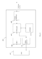
- FIG. 3 is a diagram 300 of NDE image data 138 generated by imaging device 104 .
- Image data 138 includes first internal images 302 associated with a pre-loaded state of structure 106 and second internal images 304 associated with a loaded state of structure 106 . More specifically, prior to a mechanical load (not shown) and/or thermal load (not shown) being applied to structure 106 , imaging device 104 obtains first internal images 302 of bondline 112 . Once the mechanical load and/or thermal load is applied to structure 106 , imaging device 104 obtains second internal images 304 of bondline 112 . At least one of first pattern 118 and second pattern 120 changes from the first internal images 302 to the second internal images 304 , due to stress and strain caused by the mechanical load and/or thermal load. More specifically, at least one of first pattern 118 and second pattern 120 undergoes deformation due to the stress and strain caused by the mechanical load and/or thermal load.
- First internal images 302 include first side data 306 and second side data 308 , corresponding to first side 114 and second side 116 of bondline 112 .
- first side data 306 includes first angle data 314 and second angle data 316 . More specifically, first angle data 314 represents a view of first side 114 from a first angle and second angle data 316 represents a view of first side 114 from a second angle that is different from the first angle.
- Imaging device 104 and/or analysis device 102 calculates parallax between first angle data 314 and second angle data 316 and generates a three dimensional image of first side 114 .
- second side data 308 includes first angle data 318 and second angle data 320 .
- second internal images 304 include first side data 310 , including first angle data 322 and second angle data 324
- second side data 312 includes first angle data 326 and second angle data 328 of bondline 112 when structure 106 is mechanically and/or thermally loaded.
- Analysis computing device 102 transmits instructions 136 to imaging device 104 to obtain image data 138 for each location 122 , 124 , 126 , 128 , 130 , 132 , and 134 along bondline 112 . As described in more detail herein, analysis computing device 102 compares (i.e., correlates) first internal images 302 with second internal images 304 .
- analysis computing device 102 By comparing first internal images 302 with second internal images 304 , analysis computing device 102 detects and measures deformations in first pattern 118 and/or second pattern 120 between the pre-loaded state and the loaded state of structure 106 . Based on the comparison, analysis computing device 102 determines at least one strain-related property of bondline 112 .
- FIG. 4 is a diagram of an example computing device 402 .
- Computing device 402 is representative of analysis computing device 102 .
- imaging device 104 includes one or more components of computing device 402 .
- imaging device 104 is included within analysis computing device 102 .
- Computing device 402 includes one or more processors 405 for executing instructions.
- executable instructions are stored in a memory device 410 .
- Processor 405 may include one or more processing units (e.g., in a multi-core configuration).
- One or more memory devices 410 are any one or more devices allowing information such as executable instructions and/or other data to be stored and retrieved.
- One or more memory devices 410 may include one or more computer-readable media.
- Computing device 402 also includes at least one media output component 415 for presenting information to a user 401 .
- Media output component 415 is any component capable of conveying information to user 401 .
- media output component 415 includes an output adapter such as a video adapter and/or an audio adapter.
- An output adapter is operatively coupled to processor 405 and operatively couplable to an output device such as a display device (e.g., a liquid crystal display (LCD), organic light emitting diode (OLED) display, cathode ray tube (CRT), or “electronic ink” display) or an audio output device (e.g., a speaker or headphones).
- a display device e.g., a liquid crystal display (LCD), organic light emitting diode (OLED) display, cathode ray tube (CRT), or “electronic ink” display
- an audio output device e.g., a speaker or headphones.
- computing device 402 includes an input device 420 for receiving input from user 401 .
- Input device 420 may include, for example, a keyboard, a pointing device, a mouse, a stylus, a touch sensitive panel (e.g., a touch pad or a touch screen), a gyroscope, an accelerometer, a position detector, or an audio input device.
- a single component such as a touch screen may function as both an output device of media output component 415 and input device 420 .
- Computing device 402 additionally includes a communication interface 425 , which is communicatively couplable to another device such as imaging device 104 .
- Communication interface 425 may include, for example, a wired or wireless network adapter or a wireless data transceiver for use with a mobile phone network (e.g., Global System for Mobile communications (GSM), 3G, 4G or Bluetooth) or other mobile data network (e.g., Worldwide Interoperability for Microwave Access (WIMAX)).
- GSM Global System for Mobile communications
- 3G, 4G or Bluetooth Wireless Fidelity
- WIMAX Worldwide Interoperability for Microwave Access
- Stored in one or more memory devices 410 are, for example, computer-readable instructions for providing a user interface to user 401 via media output component 415 and, optionally, receiving and processing input from input device 420 .
- a user interface may include, text, graphics, and/or sound that enable user 401 to interact with computing device 402 , for example to control operations of computing device 402 and/or view output based, for example, on data (e.g., image data 138 ) transmitted from another device (e.g., imaging device 104 ).
- the computer-readable instructions additionally cause computing device 402 to analyze image data 138 and determine at least one strain-related property of bondline 112 based, at least in part, on image data 138 .
- FIG. 5 is a flowchart of an example process 500 for analyzing bondline 112 .
- a manufacturer or assembler applies 502 a pattern (e.g., first pattern 118 and/or second pattern 120 ) to bondline 112 .
- a manufacturer of adhesive 113 includes materials having differing reflectivity into adhesive 113 .
- a manufacturer or assembler of structure 106 applies the pattern (e.g., first pattern 118 and/or second pattern 120 ) to a surface (e.g., first side 114 and/or second side 116 ) of bondline 112 , for example by spraying or spackling materials, or applying a scrim (e.g., first scrim 119 and/or second scrim 121 ) to bondline 112 (e.g., adhesive 113 ).
- the assembler or manufacturer cures bondline 112 .
- analysis computing device 102 maps 504 patterns (e.g., first pattern 118 and/or second pattern 120 ) associated with bondline 112 , and records 506 images of bondline 112 , for example first internal images 302 , in memory 410 .
- the manufacturer or assembler applies 508 a mechanical and/or thermal load to structure 106 .
- Analysis computing device 102 maps 504 patterns (e.g., first pattern 118 and/or second pattern 120 ) associated with bondline 112 , and records 510 images of bondline 112 , for example second internal images 304 , in memory 410 .
- analysis computing device 102 correlates 512 (e.g., compares) the images (e.g., first internal images 302 and second internal images 304 ), calculates 514 displacements (i.e., deformations) in the patterns (e.g., first pattern 118 and/or second pattern 120 ) between the pre-loaded state (e.g., first internal images 302 ) and the loaded state (e.g., second internal images 304 ).
- analysis computing device 102 calculates 516 a strain field based on the displacements. Additionally, analysis computing device 102 calculates 517 a stress field based on the calculated strain field from 516 in the bondline. Additionally, analysis computing device 102 inputs 518 stress and strain information into an engineering model associated with structure 106 . Additionally, analysis computing device 102 maps 520 properties of the bond along bondline 112 (i.e., for each of a plurality of locations along bondline 112 ) that can be correlated to strain, such as disbond, “kissing” bond, degraded or failed adhesive.
- analysis computing device 102 provides 522 the mapped properties along bondline 112 to a lifing prediction and maintenance planning model (e.g., one or more S-N curves) and predicts a lifetime for bondline 112 and/or a schedule of one or more maintenance periods for bondline 112 .
- a lifing prediction and maintenance planning model e.g., one or more S-N curves
- FIG. 6 is a flowchart of an example process 600 carried out by analysis computing device 102 for analyzing bondline 112 .
- analysis computing device 102 obtains 602 , from first side 114 of structure 106 , for example from image data 138 , at least one first internal image (e.g., first internal images 302 ) of structure 106 .
- pre-loaded state does not mean that the bondline or structure is completely unstressed. Rather, “pre-loaded state” means that a particular load used for testing has not been applied to the bond or structure yet. Accordingly, “loaded state” means that the load used for testing has been applied.
- the at least one first internal image 302 includes at least a first pattern (e.g., first pattern 118 ) associated with bondline 112 .
- analysis computing device 102 obtains 604 , from first side 114 of structure 106 , at least one second internal image (e.g., second internal images 304 ) of structure 106 .
- the at least one second internal image 304 includes at least the first pattern (e.g., first pattern 118 ).
- analysis computing device 102 compares 606 the at least one first internal image 302 with the at least one second internal image 304 .
- analysis computing device 102 calculates and measures displacements in first pattern 118 between first internal images 302 and second internal images 304 .
- analysis computing device 102 determines 608 at least one strain-related property of bondline 112 based on the comparison.
- analysis computing device 102 determines 610 at least one stress-related property of bondline 112 based on 608 .
- at least one stress/strain-related property may be a plurality of local stress/strain-related variations of bondline 112 .
- the variations are correlated to such stress/strain-related properties as disbonds, “kissing” or zero strength bonds, or adhesive degradation or failure.
- process 600 additionally includes applying first pattern 118 to bondline 112 prior to generating at least one first internal image 302 .
- process 600 includes applying first pattern 118 to first side 114 of bondline 112 and applying second pattern 120 to second side 116 of bondline 112 , prior to obtaining at least one first internal image 302 .
- process 600 additionally includes generating at least one first internal image 302 of structure 106 that includes at least first pattern 118 and second pattern 120 when structure 106 is in the pre-loaded state and generating at least one second internal image 304 of structure 106 that includes at least first pattern 118 and second pattern 120 when structure 106 is in the loaded state.
- obtaining at least one first internal image 302 further includes generating at least one first internal image 302 using an ultrasonic array 144 .
- obtaining at least one first internal image 302 further includes generating at least one first internal image 302 using backscattered electromagnetic radiation 142 .
- obtaining at least one first internal image further includes generating a plurality of first internal images 302 , wherein each of the first internal images 302 is associated with a different angle.
- obtaining at least one second internal image 304 further includes generating a plurality of second internal images 304 , wherein each of the second internal images 304 is associated with a different angle.
- determining a strain-related property of bondline 112 further includes determining a respective strain-related property associated with each of a plurality of locations (e.g., locations 122 , 124 , 126 , 128 , 130 , 132 , and 134 ) along bondline 112 .
- process 600 additionally includes determining a predicted lifetime of bondline 112 based at least in part on the comparison of first internal images 302 to the second internal images 304 .
- Some implementations include transitioning structure 106 from the pre-loaded state to the loaded state by applying a load (e.g., a mechanical load and/or a thermal load) to structure 106 .
- process 600 includes making one or more lower strain measurements, for example to detect disbonds, kissing bonds, and/or adhesive degradation), and making higher strain measurements that produce a proof test at the level of stress applied to the structure to verify bond strength.
- a technical effect of systems and methods described herein includes at least one of: (a) obtaining, from a first side of a structure, by at least one computing device, at least one first internal image of the structure that includes at least a first pattern associated with a bondline, wherein the structure is in a pre-loaded state; (b) obtaining, from the first side of the structure, by the at least one computing device, at least one second internal image of the structure that includes at least the first pattern, wherein the structure is in a loaded state; (c) comparing, by the at least one computing device, the at least one first internal image with the at least one second internal image; (d) determining, by the at least one computing device, at least one stress/strain-related property of the bondline based on the comparison; and (e) predicting an estimated life of the bondline, whereby the estimated life provides a valuable tool for optimization of maintenance effort and enabling cost-optimal maintenance decisions.
- the methods and systems described herein enable portions of a structure that are not detectable using visible light to be analyzed using digital image correlation from a single side of the structure. Accordingly, components included within structures, such as bondlines within composite structures, may be analyzed without damaging the structure to determine at least one strain-related property and/or predicted performance of the components.
Abstract
Description
Claims (20)
Priority Applications (1)
| Application Number | Priority Date | Filing Date | Title |
|---|---|---|---|
| US14/486,461 US9443300B2 (en) | 2014-09-15 | 2014-09-15 | Systems and methods for analyzing a bondline |
Applications Claiming Priority (1)
| Application Number | Priority Date | Filing Date | Title |
|---|---|---|---|
| US14/486,461 US9443300B2 (en) | 2014-09-15 | 2014-09-15 | Systems and methods for analyzing a bondline |
Publications (2)
| Publication Number | Publication Date |
|---|---|
| US20160078607A1 US20160078607A1 (en) | 2016-03-17 |
| US9443300B2 true US9443300B2 (en) | 2016-09-13 |
Family
ID=55455204
Family Applications (1)
| Application Number | Title | Priority Date | Filing Date |
|---|---|---|---|
| US14/486,461 Active 2035-02-07 US9443300B2 (en) | 2014-09-15 | 2014-09-15 | Systems and methods for analyzing a bondline |
Country Status (1)
| Country | Link |
|---|---|
| US (1) | US9443300B2 (en) |
Families Citing this family (2)
| Publication number | Priority date | Publication date | Assignee | Title |
|---|---|---|---|---|
| US11346816B2 (en) * | 2020-05-01 | 2022-05-31 | The Boeing Company | Apparatuses, systems, and methods for detecting kissing bonds in bonded joints |
| CN117130264B (en) * | 2023-10-27 | 2024-01-05 | 深圳中宝新材科技有限公司 | Method and device for controlling bonded silver wire equipment based on side time-frequency resource |
Citations (8)
| Publication number | Priority date | Publication date | Assignee | Title |
|---|---|---|---|---|
| US20130018809A1 (en) * | 2011-07-14 | 2013-01-17 | Yi Li | Computer-implemented method and system for evaluating eco-functional properties of a product |
| US20130128026A1 (en) * | 2009-10-30 | 2013-05-23 | Sumitomo Chemical Company, Limited | Image processing device for defect inspection and image processing method for defect inspection |
| CA2823296A1 (en) | 2012-10-09 | 2014-04-09 | The Boeing Company | Nondestructive examination of structures having embedded particles |
| US20140160279A1 (en) | 2012-12-06 | 2014-06-12 | The Boeing Company | Multiple-Scale Digital Image Correlation Pattern and Measurement |
| US20150215584A1 (en) * | 2014-01-28 | 2015-07-30 | The Boeing Company | Non-Destructive Evaluation of Structures Using Motion Magnification Technology |
| US20150253266A1 (en) * | 2012-10-19 | 2015-09-10 | Resodyn Corporation | Methods and systems for detecting flaws in an object |
| US20150319418A1 (en) * | 2012-12-02 | 2015-11-05 | Segoma Ltd. | Devices and methods for generating a 3d imaging dataset of an object |
| US20150323424A1 (en) * | 2014-05-06 | 2015-11-12 | GM Global Technology Operations LLC | Test method |
-
2014
- 2014-09-15 US US14/486,461 patent/US9443300B2/en active Active
Patent Citations (9)
| Publication number | Priority date | Publication date | Assignee | Title |
|---|---|---|---|---|
| US20130128026A1 (en) * | 2009-10-30 | 2013-05-23 | Sumitomo Chemical Company, Limited | Image processing device for defect inspection and image processing method for defect inspection |
| US20130018809A1 (en) * | 2011-07-14 | 2013-01-17 | Yi Li | Computer-implemented method and system for evaluating eco-functional properties of a product |
| CA2823296A1 (en) | 2012-10-09 | 2014-04-09 | The Boeing Company | Nondestructive examination of structures having embedded particles |
| US20140098936A1 (en) | 2012-10-09 | 2014-04-10 | The Boeing Company | Nondestructive examination of structures having embedded particles |
| US20150253266A1 (en) * | 2012-10-19 | 2015-09-10 | Resodyn Corporation | Methods and systems for detecting flaws in an object |
| US20150319418A1 (en) * | 2012-12-02 | 2015-11-05 | Segoma Ltd. | Devices and methods for generating a 3d imaging dataset of an object |
| US20140160279A1 (en) | 2012-12-06 | 2014-06-12 | The Boeing Company | Multiple-Scale Digital Image Correlation Pattern and Measurement |
| US20150215584A1 (en) * | 2014-01-28 | 2015-07-30 | The Boeing Company | Non-Destructive Evaluation of Structures Using Motion Magnification Technology |
| US20150323424A1 (en) * | 2014-05-06 | 2015-11-12 | GM Global Technology Operations LLC | Test method |
Non-Patent Citations (10)
| Title |
|---|
| Bruck, H.A. et al., 1989, "Digital Image Correlation Using Newton-Raphson Method of Partial Differential Correction," Experimental Mechanics, 29(3), pp. 261-267. |
| Chu, T.C. et al., 1985, "Applications of Digital Image Correlation Techniques to Experimental Mechanics," Experimental Mechanics, 25(3), pp. 232-244. |
| Digital Imaging Techniques in Experimental Stress Analysis. Peters et al. 1982. * |
| Helm, J. D. et al., 1996, "Improved three-dimensional image correlation for surface displacement measurement," Optical Engineering, 35(7), pp. 1911-1920. |
| Kahnjetter, Z. L et al., 1990, "3-Dimensional Displacement Measurements Using Digital Image Correlation and Photogrammic Analysis," Experimental Mechanics, 30(1), pp. 10-16. |
| Luo, P.F. et al., 1993, "Accurate Measurement of 3-Dimensional Deformations in Deformable and Rigid Bodies Using Computer Vision," Experimental Mechanics, 33(2), pp. 123-132. |
| Peters, W.H. et al., 1982, "Digital Imaging Techniques in Experimental Stress Analysis," Optical Engineering, 21(3), pp. 427-431. |
| Peters, W.H. et al., 1983, "Application of Digital Correlation Methods to Rigid Body Mechanics," Optical Engineering, 22(6), pp. 738-742. |
| Sutton, M.A. et al., 1986, "Application of an Optimized Digital Correlation Method to Planar Deformation Analysis," Image and Vision Computing, 4(3), pp. 143-150. |
| Testing of Structural Joints. Stanley S. Smeltzer III. Dec. 2010. * |
Also Published As
| Publication number | Publication date |
|---|---|
| US20160078607A1 (en) | 2016-03-17 |
Similar Documents
| Publication | Publication Date | Title |
|---|---|---|
| Tabjula et al. | Outlier analysis for defect detection using sparse sampling in guided wave structural health monitoring | |
| JP7156782B2 (en) | Wrinkle Characterization and Performance Prediction for Composite Structures | |
| Kong et al. | Vision‐based fatigue crack detection of steel structures using video feature tracking | |
| Hassani et al. | A systematic review of advanced sensor technologies for non-destructive testing and structural health monitoring | |
| US8965100B2 (en) | Ultrasonic modeling for inspection of composite irregularities | |
| Lu et al. | Detecting damage size and shape in a plate structure using PZT transducer array | |
| US8332165B1 (en) | Analysis of ultrasonic images using a decomposition process | |
| Gupta et al. | A review of sensing technologies for non-destructive evaluation of structural composite materials | |
| Grabowski et al. | Time–distance domain transformation for Acoustic Emission source localization in thin metallic plates | |
| Lee et al. | Gage‐free stress estimation of a beam‐like structure based on terrestrial laser scanning | |
| JP2017062226A5 (en) | ||
| US9360418B2 (en) | Nondestructive inspection using hypersound | |
| US10139376B2 (en) | System for sensing and locating delamination | |
| JP2019197040A (en) | Laser ultrasound scanning for visualizing damage or irregularities | |
| US9595092B2 (en) | Methods and systems for inspection of composite irregularities | |
| US8707787B1 (en) | Time delay based health monitoring system using a sensor network | |
| US20170248551A1 (en) | Inspection of Structures | |
| US10126122B2 (en) | Ultrasonic inspection of wrinkles in composite objects | |
| Qiu et al. | A scanning spatial-wavenumber filter and PZT 2-D cruciform array based on-line damage imaging method of composite structure | |
| Shrestha et al. | Image processing–based real‐time displacement monitoring methods using smart devices | |
| US20170212083A1 (en) | Multi-layer ultrasound imagers | |
| US20160123934A1 (en) | Apparatuses, systems, and methods for inspecting a component | |
| Qiu et al. | Design of an all-digital impact monitoring system for large-scale composite structures | |
| US9443300B2 (en) | Systems and methods for analyzing a bondline | |
| Mohammadkhorasani et al. | Augmented reality-computer vision combination for automatic fatigue crack detection and localization |
Legal Events
| Date | Code | Title | Description |
|---|---|---|---|
| AS | Assignment |
Owner name: THE BOEING COMPANY, ILLINOIS Free format text: ASSIGNMENT OF ASSIGNORS INTEREST;ASSIGNORS:GEORGESON, GARY E.;POUDEL, ANISH;CHU, TSUCHIN;REEL/FRAME:033741/0636 Effective date: 20140912 |
|
| AS | Assignment |
Owner name: THE BOEING COMPANY, ILLINOIS Free format text: ASSIGNMENT OF ASSIGNORS INTEREST;ASSIGNOR:GROSSNICKLE, JAMES A.;REEL/FRAME:033750/0087 Effective date: 20140914 |
|
| FEPP | Fee payment procedure |
Free format text: PAYOR NUMBER ASSIGNED (ORIGINAL EVENT CODE: ASPN); ENTITY STATUS OF PATENT OWNER: LARGE ENTITY |
|
| STCF | Information on status: patent grant |
Free format text: PATENTED CASE |
|
| MAFP | Maintenance fee payment |
Free format text: PAYMENT OF MAINTENANCE FEE, 4TH YEAR, LARGE ENTITY (ORIGINAL EVENT CODE: M1551); ENTITY STATUS OF PATENT OWNER: LARGE ENTITY Year of fee payment: 4 |
|
| MAFP | Maintenance fee payment |
Free format text: PAYMENT OF MAINTENANCE FEE, 8TH YEAR, LARGE ENTITY (ORIGINAL EVENT CODE: M1552); ENTITY STATUS OF PATENT OWNER: LARGE ENTITY Year of fee payment: 8 |