EP2720007B1 - Flüssigkeitsnivellierungssystem mit Blasenabweisungsreflektoren - Google Patents
Flüssigkeitsnivellierungssystem mit Blasenabweisungsreflektoren Download PDFInfo
- Publication number
- EP2720007B1 EP2720007B1 EP13182660.4A EP13182660A EP2720007B1 EP 2720007 B1 EP2720007 B1 EP 2720007B1 EP 13182660 A EP13182660 A EP 13182660A EP 2720007 B1 EP2720007 B1 EP 2720007B1
- Authority
- EP
- European Patent Office
- Prior art keywords
- reflector
- target
- stillwell
- transducer
- tapered
- Prior art date
- Legal status (The legal status is an assumption and is not a legal conclusion. Google has not performed a legal analysis and makes no representation as to the accuracy of the status listed.)
- Not-in-force
Links
Images


Classifications
-
- G—PHYSICS
- G01—MEASURING; TESTING
- G01F—MEASURING VOLUME, VOLUME FLOW, MASS FLOW OR LIQUID LEVEL; METERING BY VOLUME
- G01F23/00—Indicating or measuring liquid level or level of fluent solid material, e.g. indicating in terms of volume or indicating by means of an alarm
- G01F23/22—Indicating or measuring liquid level or level of fluent solid material, e.g. indicating in terms of volume or indicating by means of an alarm by measuring physical variables, other than linear dimensions, pressure or weight, dependent on the level to be measured, e.g. by difference of heat transfer of steam or water
- G01F23/28—Indicating or measuring liquid level or level of fluent solid material, e.g. indicating in terms of volume or indicating by means of an alarm by measuring physical variables, other than linear dimensions, pressure or weight, dependent on the level to be measured, e.g. by difference of heat transfer of steam or water by measuring the variations of parameters of electromagnetic or acoustic waves applied directly to the liquid or fluent solid material
- G01F23/296—Acoustic waves
- G01F23/2962—Measuring transit time of reflected waves
-
- G—PHYSICS
- G01—MEASURING; TESTING
- G01S—RADIO DIRECTION-FINDING; RADIO NAVIGATION; DETERMINING DISTANCE OR VELOCITY BY USE OF RADIO WAVES; LOCATING OR PRESENCE-DETECTING BY USE OF THE REFLECTION OR RERADIATION OF RADIO WAVES; ANALOGOUS ARRANGEMENTS USING OTHER WAVES
- G01S15/00—Systems using the reflection or reradiation of acoustic waves, e.g. sonar systems
- G01S15/88—Sonar systems specially adapted for specific applications
Definitions
- the present invention relates to reflectors for use in liquid level gauging systems such as those used in fuel tanks, and more particularly to reflectors that shed bubbles.
- a variety of devices are known in the art for monitoring and detecting liquid levels, for example, for determining the level of remaining fuel in a fuel tank. Of such devices, many include ultrasonic signals to determine liquid levels. Such ultrasonic liquid level gauging systems typically employ ultrasonic reflectors to prevent signal loss at tank full conditions, assisting in calibrating gauges, measuring the speed-of-sound through a fluid, and/or as caps on stillwells.
- Ultrasonic liquid level gauging system 1 typically includes a transducer 8 that is configured to send and receive ultrasound signals 10 from the bottom of a fluid storage tank or container to the fluid surface. At the fluid surface, the sound typically reflects back to the transducer 8. By monitoring the time it takes for the signal to leave and return to transducer 8, in conjunction with knowing the speed of sound through the fluid, it is possible to calculate the distance from the fluid surface to transducer 8. Such techniques can be used to determine fuel levels in an aircraft fuel tank 3, for example. Typically, transducer 8 is located at or near the bottom of the aircraft fuel tank 3, in order to monitor the fluid level over a range of levels within the fuel tank.
- Fig. 3 shows an ultrasonic reflector within the ultrasonic liquid level gauging system 1 of Fig. 2 , that is representative of the prior art.
- Ultrasonic reflectors for this purpose typically include reflector targets 4 located at a predetermined distance D from the ultrasonic transmit and receive transducer 8.
- Reflector target 4 is typically a flat piece of metal oriented orthogonally to the ultrasonic beam.
- Reflector target 4 can be oriented within a stillwell 2 as a cap, or independent of a stillwell 2.
- Fig. 2 shows a stillwell 2 that is representative of the prior art.
- Stillwells 2 are hollow tubes disposed in a fluid that can be used in conjunction with flat reflector targets 4.
- the stillwell 2 is aligned over transducer 8 and extends from the bottom of the storage towards the top of the storage.
- Stillwell 2 guides the ultrasound signals 10, prevents echoes from tank structures, reduces liquid level slosh above transducer 8, calms liquid surface ripples and reduces bubbles and debris from the path of ultrasound signal 10.
- Some stillwells 2 use reflector targets 4 as caps on their top end in order to ensure that a signal is reflected back to the transducer 8 when liquid levels are higher than the top of the stillwell 2. Without such a reflector target 4 cap, ultrasonic signal 10 may not reflect back to transducer 8 once it leaves the stillwell 2 when liquid levels are high, for example when tank 3 is completely full of fuel, signals sent from transducer 8 go directly out of tank 3 without being reflected back, resulting in a signal loss. Such signal loss is undesirable because it can be confused with failure of transducer 8.
- typical flat reflector targets 4, used for this purpose collect bubbles at reflective surface 6 that diminish, distort or eliminate the return ultrasound pulse.
- the shape of flat reflective surface 6 limits the reflector target 4 positioning options within a fluid storage container, due to the need for precise alignment.
- Reflectors are also used in ultrasonic liquid level gauging systems 1 as velocimeter targets.
- a submerged velocimeter target set a known distance from an ultrasonic transmit and receive transducer, can be used to measure the speed of sound in a fluid to improve liquid level monitoring in ultrasonic liquid level gauging system.
- Velocimeters can be located in a common stillwell with the liquid level gauge or independently. Velocimeters are known in the art to be flat metallic surfaces submerged in fluid.
- the flat velocimeter targets can experience similar drawbacks as those experienced by the flat reflector caps mentioned above.
- flat velocimeter targets pose more drawbacks when located outside of the stillwell because the ultrasonic signals will not be guided by the stillwell. When located outside of the still well, the flat target's alignment with the transducer is much more critical.
- US 8248888 discloses a system according to the preamble of claim 1.
- the subject invention is directed to a new and useful reflector target that sheds bubbles.
- the invention provides a liquid level gauging system comprising a fluid storage tank and a reflector target disposed in the fluid storage tank, the reflector target comprising: a reflector defining a tapered reflector surface, the reflector including an apex opening and an opposed base opening; the perimeter of the base opening is larger than the perimeter of the apex opening; the tapered reflector surface extends between the openings forming a tapered passage between the two openings; the apex opening and the base opening are aligned such that a center of the base opening and a center of the apex opening define a vertical axis; and characterized in that the apex opening is disposed higher along the vertical axis within the fluid storage, tank than the base opening and wherein the tapered reflector surface is configured to resist the accumulation of surface bubbles on the reflector surface by movement of bubbles along the reflector surface out through the apex opening.
- the tapered reflector surface can be a truncated forty-five degree cone shape or a truncated corner-cube retro-reflector shape.
- the tapered reflector surface can be formed within a cylindrical cap.
- the reflector target can also be disposed in a stillwell including a hollow tube defining a vertical axis and having a first end and a second end.
- the stillwell is configured to reduce surface level variations in a fluid.
- the base opening of the tapered reflector surface can face the first end of the stillwell, and the tapered reflector surface can be configured to allow fluid flow through the stillwell from the base opening of the reflector surface to the apex opening of the reflector surface.
- the reflector target can be adapted and configured for use in a fuel tank to reflect signals sent from a transducer back to the point of origin. It is also contemplated that the reflector target can be configured for use as a velocimeter target in a liquid level gauging system.
- the liquid level gauging system can be a transducer configured to transmit and receive signals.
- the velocimeter target is positioned at a predetermined distance from the transducer for determining the speed of sound in a liquid in which the velocimeter is submerged.
- the system includes a transducer configured to send and receive signals and a stillwell, as described above, operatively associated with the transducer for guiding the signals sent and received by the transducer.
- the system further includes a reflector target, as described above, mounted in the stillwell a predetermined distance from the transducer.
- the liquid level gauging system can include a reflector target configured for use as a velocimeter target.
- a velocimeter target is similar to the reflector target as described above.
- the tapered velocimeter surface just as the tapered reflector surface, is configured to resist accumulation of surface bubbles on the tapered velocimeter surface by movement of bubbles along the tapered velocimeter surface out through the apex opening.
- the velocimeter target can be dimensionally and proportionally different than the reflector target.
- the apex opening of the velocimeter target can have a larger perimeter than the apex opening of the reflector target.
- the tapered velocimeter surface is a forty-five degree conical surface
- the apex and base openings of the reflector are circular.
- the centers of the circular apex opening and the circular base opening can be aligned along the vertical axis.
- the velocimeter target can be positioned below the reflector target along the vertical axis, i.e. closer to the transducer for speed of sound measurements.
- the conical velocimeter surface of the velocimeter reflector is configured to reflect a portion of the signals back to the transducer and to reduce the accumulation of surface bubbles on the conical velocimeter reflector surface.
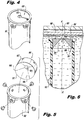
- Fig. 4 a partial view of an exemplary embodiment of the ultrasonic reflector target in accordance with the invention is shown in Fig. 4 and is designated generally by reference character 100.
- the systems and methods of the invention can be used for improved monitoring and detecting of liquid levels in fluid storage tanks, such as aircraft fuel tanks.
- Ultrasonic reflector target 100 is mounted to stillwell 102.
- Target 100 includes a reflector 104 defining a tapered reflector surface 106, as shown in Fig. 5 .
- Reflector 104 includes an apex opening 103 and an opposed base opening 101, wherein base opening 101 tapers to the side of stillwell 102 has a larger perimeter than apex opening 103.
- Tapered reflector surface 106 extends between the two openings forming a tapered passage 105 there-between, as included in Fig. 6 .
- Tapered reflector surface 106 is configured to resist the accumulation of surface bubbles on reflector surface 106 by facilitating movement of bubbles along reflector surface 106 out through apex opening 103.
- tapered reflector surface 106 is a truncated forty-five degree cone shape.
- tapered reflector surface 106 can also be formed as a truncated corner-cube, such as a corner-cube retro-reflector, without departing from the scope of the invention.
- Tapered reflector surface 106 reduces or eliminates the need to perfectly align reflector target 100 with transducer 8.
- Tapered reflector surface 106 reflects at least a partial ultrasound signal back to transducer 8 even if reflector surface 106 and transducer 8 are not in perfect vertical alignment along axis A due to the tapered shape of the reflector surface 106. While described above in the exemplary context of having a forty-five degree tapered surface, those skilled in the art will readily appreciate that deviations from forty-five degrees may also provide exemplary signal return.
- tapered reflector surface 106 is formed within a cylindrical cap 107.
- Cylindrical cap 107 is disposed within a stillwell 102 as shown in Fig. 5 , but could be mounted to the tank on the outside of a stillwell 102.
- tapered reflector surface 106 does not have to be formed in cylindrical cap 107, but could instead be a thin walled cone, without departing from the scope of the invention.
- apex opening 103 and base opening 101 are aligned such that a center of base opening 101 and a center of apex opening 103 define a vertical axis A, for example, with apex opening 103 disposed higher along vertical axis A than base opening 101.
- base opening 101 can be any suitable shape to match the inner surface of the stillwell and apex opening 103 can be round for a forty-five degree truncated cone shape and triangular for a truncated corner-cube retro-reflector shape, without departing from the scope of the invention.
- ultrasonic reflector target 100 is disposed in stillwell 102 the hollow tube of which defines vertical axis A. Fluid surfaces are subject to sloshing and rippling, especially in moving vehicles such as aircraft. Stillwell 102 is configured to reduce surface level variations in a fluid, guide the ultrasonic signal and reduce bubbles and debris from the ultrasound signal path.
- ultrasonic liquid level gauging system 109 includes a transducer 108 configured to send and receive ultrasonic signals and a stillwell 102 as described above. Stillwell 102 is operatively associated with transducer 108 for guiding the ultrasonic signals sent and received by transducer 108. Stillwell 102 includes a first end 110 and a second end 112. Base opening 101 of reflector target 100 faces first end 110 of stillwell 102, while apex opening 103 faces away from first end 110. The system further includes an ultrasonic reflector target 100, as described above, mounted in stillwell 102 a predetermined distance from transducer 108.
- tapered reflector surface 106 is configured to allow fluid flow through stillwell 102 from base opening 101 of reflector surface 106 to apex opening 103 of reflector surface 106. This allows for shedding of bubbles rather than accumulation of bubbles on reflector surface 106.
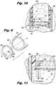
- Velocimeter target 200 is part of liquid level gauging system 109 and is configured and adapted to receive an ultrasonic signal 210 from transducer 108 and return a partial ultrasonic signal 212 to transducer 108. Velocimeter target 200 is positioned at a predetermined distance from transducer 108, within stillwell 102, where it preferably remains submerged at all times. This allows the velocimeter to monitor the speed of sound in the liquid regardless of liquid levels.
- Velocimeter target 200 includes a velocimeter reflector 204 defining a tapered velocimeter surface 206.
- Velocimeter reflector 204 includes an apex opening 203 and an opposed base opening 201, wherein base opening 201 has a larger perimeter than apex opening 203 and base opening 201 faces first end 110 of the hollow tube of stillwell 102 with tapered velocimeter surface 206 extends between openings 201, 203 forming a tapered passage 205 between two openings 201, 203, much as described above.
- Velocimeter target 200 is positioned below reflector target 100 along vertical axis A, i.e. closer to transducer 108.
- tapered velocimeter surface 206 is a forty-five degree conical surface, and apex 203 and base openings 201 of velocimeter reflector 204 are circular. The centers of circular apex opening 203 and circular base 201 opening are aligned along vertical axis A.
- tapered velocimeter surface 206 can vary in surface area size and does not have to be a forty-five degree cone shape.
- tapered velocimeter surface 206 can form a truncated corner-cube retro-reflector shape, without departing from the scope of the invention.
- Apex opening 203 of velocimeter target 200 can have a larger perimeter than apex 103 opening of reflector target 100.
- base opening 201 can be determined by the inner diameter of the stillwell and that the velocimeter target 200 must allow most of the ultrasound to pass, but have a tapered velocimeter surface 206 large enough to return a partial signal.
- the size of the tapered velocimeter surface 206 is also dependent upon the transducer beam shape, distance from velocimeter to transducer, and electronics.
- tapered velocimeter surface 206 is formed within a solid cylindrical cap 207.
- tapered velocimeter surface 206 can be used without cylindrical cap 207, for example, a thin-walled cone, without departing from the scope of the invention.
- tapered velocimeter surface 206 is configured to resist accumulation of surface bubbles on tapered velocimeter surface 206 by movement of bubbles along tapered velocimeter surface 206 out through apex opening 203.
- tapered velocimeter surface 206 of velocimeter reflector 204 is shown reflecting a portion of the ultrasonic signals back to transducer 108 and to reduce the accumulation of surface bubbles on tapered velocimeter surface 206.
- Tapered velocimeter surface 206 is configured to reflect ultrasonic signal 210 and return a partial ultrasonic signal 212 to transmit/receive transducer 108, while the remainder of ultrasonic signal 210 passes through apex opening 203, up stillwell 102 to tapered reflector surface 106, or the liquid surface, whichever is lower.
- the remainder of ultrasonic signal 210 is reflected from the fluid surface back to transducer 108.
- velocimeter target 300 positioned within stillwell 302 at a predetermined distance from a dedicated transmit/receive transducer 308.
- velocimeter reflector 304 is shown with a larger tapered velocimeter surface 306 than tapered velocimeter surface 206 of Figs. 8-11 .
- velocimeter surface 306, as shown in Fig. 12 utilizes its own transmit and receive transducer. Therefore, an ultrasonic signal from transducer 308 does not need to pass through apex opening 303 of velocimeter reflector 304. The only signal to be received by transmit/receive 308 transducer is returned from velocimeter surface 306.
- ultrasonic liquid level gauging system 409 includes ultrasonic reflector target 400 having a reflector 404 defining a tapered reflector surface 406.
- Reflector 404 includes an apex opening 403 and an opposed base opening 401, wherein base opening 401 has a larger perimeter than apex opening 403.
- Tapered reflector surface 406 extends between openings forming a tapered passage 405 there-between.
- Tapered reflector surface 406 is configured to resist the accumulation of surface bubbles on reflector surface 406 by movement of bubbles along reflector surface 406 out through apex opening 403, as described above.
- ultrasonic liquid level gauging system 409 is a top-off system and does not include a stillwell, e.g. stillwell 102, but is affixed to the top of a liquid storage by a bracket 402 or any other suitable means.
- ultrasonic reflector target 400 has a dedicated transducer 408.
- Transducer 408 and center of ultrasonic reflector target 400 need not be aligned along the same vertical axis B.
- Tapered reflector surface 406 will reflect at least a portion of the ultrasonic signal back to transducer 408 even if somewhat misaligned, due to the shape of reflector surface 406.
- reflector 404 is shown as a truncated forty-five degree cone shape reflector, it is advantageous to use a truncated corner-cube retro-reflector when a stillwell is not being used because a truncated corner-cube retro-reflector better reflects the signal back to the transducer when the signal is misaligned.
- velocimeter target 300, stillwell 302 and transducer 308 can be used in conjunction with reflector target 400, transducer 408 and ultrasonic liquid level gauging system 409 for velocimeter enhanced liquid level gauging.
- Each reflector target 300 and 400 is operative with its own respective transmit and receive transducers 308, 408.
- Stillwell 302, along with velocimeter target 300 and transducer 308, can be disposed in one portion of the fluid storage tank, while reflector target 400 and transducer 408 can be disposed in another portion of the fluid storage.
- velocimeter target 500 is shown along with ultrasonic reflector target 800.
- velocimeter target 500 is similar to velocimeter target 200 as shown in Figs. 8-11 .
- velocimeter target 500 is affixed to bracket 502 above transducer 508.
- Ultrasonic reflector target 800 is similar to ultrasonic reflector target 400 of Fig. 13 .
- the relative dimensions and proportions of reflector target 800 and bracket 802 are different than those shown Fig. 13 .
- Tapered reflector surface 506 will reflect at least a portion of the ultrasonic signal back to transducer 508 even if somewhat misaligned, due to the slope of reflector surface 506.
- velocimeter and reflector targets 100, 200, 300, 400, 500 and 800 can vary, so long as their respective reflector surfaces 106, 206, 306, 406, 506 and 806 are tapered at forty-five degrees or are a truncated corner-cube retro-reflector.
- FIG. 15 an enlarged cross section of Fig. 14 is shown.
- the enlarged cross section shows tapered velocimeter surface 506 is configured to reflect signal 510 and return a partial signal 512 to transducer 508, while the remaining portion of signal 510 passes through apex opening 503 to reflector surface 806.
- Signals 510 and 512 are depicted schematically.
- signal 510 is reflected from ultrasonic reflector surface 806 and return signal 514 is reflected back to transducer 508.
- an ultrasonic reflector target 600 includes a reflector 604 defining a tapered reflector surface 606 shaped as a truncated corner-cube retro-reflector.
- Reflector 604 includes an apex opening 603 and an opposed base opening 601, wherein base opening 601 has a larger perimeter than apex opening 603.
- Tapered reflector surface 606 extends between base opening 601 and apex opening 603, forming a tapered passage 605 there-between.
- Tapered reflector surface 606 is configured to resist the accumulation of surface bubbles on reflector surface 106 by movement of bubbles along reflector surface 606 out through apex opening 603.
- floats 610 are mounted to ultrasonic reflector target 600.
- Floats 610 allow ultrasonic reflector target 600 to be disposed within a fluid storage tank without being attached to a stillwell or bracketed to the tank.
- floats 610 allow ultrasonic reflector target 600 to rise and fall with the fluid level. This varies from embodiments described above where ultrasonic reflector targets 100, 400 and 800 were disposed at a predetermined distance from transducers 108, 408 and 808.
- floats 610 can be utilized with other ultrasonic reflectors, e.g. ultrasonic reflector targets 100 and 400.
- Stillwell 602 is used to guide ultrasonic reflector target 600 and ensure that ultrasonic reflector target 600 remains substantially centered above transducer 608.
- Transducer 608 is located inside the fluid storage tank.
- a stillwell e.g. stillwell 602 is not necessary in all circumstances, for example, reflector target 600 could be floating on a fluid surface without stillwell 602 because the truncated corner-cube retro-reflector shape is configured to return a signal to the transducer 608 despite misalignments.
- ultrasonic reflector target 600 of Fig. 17 is shown.
- transducer 708 is located outside of the fluid storage tank.
- an ultrasonic signal transmitted from transducer 708 outside of the fluid storage tank might be weaker once in the fluid storage tank than the signal transmitted from transducer 608, within the tank.
- Reflecting surface 606 is able to return even a weak ultrasonic signal originating from outside of the tank.
- the truncated corner-cube retro-reflector shape of reflector surface 606 gives a strong return signal compared to a reflection from the fluid surface, despite the weakened signal received given the reflector geometry and bubble shedding.
- ultrasonic liquid level gauging systems 709 that locate transducers, e.g. transducer 708, on the outside of the tank, eliminate the danger of wires carrying energy into a fluid storage that contains fuel or other combustible.
- the transmission of an ultrasonic signal through a fluid storage tank wall can distort, misalign and diminish its amplitude. But, ultrasonic reflector target 600 will provide improved reflecting performance despite the weakened ultrasonic signal.
- the composition of the target must have an acoustic impedance that is significantly different from the liquid to assure a strong reflection.
- the acoustic impedance is related to the material's density.
- a metal such as aluminum is more dense than most liquids and is a good choice though denser metals will give a marginal improvement.
- a dense plastic or ceramic can be used.
- a liquid-to-air (or vacuum) interface would also give a good reflection since air is less dense than liquids.
- a plastic ultrasonic reflector target 600 that encapsulates air can be used as a reflector.
- embodiments of the present invention include a tapered reflector surface, e.g. reflector surface 106, that resists the accumulation of surface bubbles on the reflector surface by movement of bubbles along the reflector surface out through the apex opening. With reduced bubble accumulation, the ultrasonic signal is less likely to be diminished, distorted or eliminated, therein reducing the possibility of an undesirable signal loss.
- embodiments of the present invention increase target positioning options within a fluid storage container, due to the tapered reflector surface.
Landscapes
- Physics & Mathematics (AREA)
- Acoustics & Sound (AREA)
- Electromagnetism (AREA)
- Thermal Sciences (AREA)
- Fluid Mechanics (AREA)
- General Physics & Mathematics (AREA)
- Measurement Of Levels Of Liquids Or Fluent Solid Materials (AREA)
Claims (11)
- Flüssigkeitsnivellierungssystem, das einen Fluidspeichertank und ein Reflektorziel (100; 200; 300; 400; 500; 600), das in dem Fluidspeichertank angeordnet ist, umfasst, wobei das Reflektorziel Folgendes umfasst:einen Reflektor (104...604), der eine abgeschrägte Reflektorfläche (106...606) definiert,wobei der Reflektor (104...604) eine Scheitelöffnung (103...603) und eine gegenüberliegende Basisöffnung (101...601) umfasst;wobei der Durchmesser der Basisöffnung (101...601) größer ist als der Durchmesser der Scheitelöffnung (103...603);wobei die abgeschrägte Reflektorfläche (106...606) sich zwischen den Öffnungen erstreckt und einen abgeschrägten Durchgang (105...605) zwischen den zwei Öffnungen bildet;wobei die Scheitelöffnung (103...603) und die Basisöffnung (101...601) derartig ausgerichtet sind, dass ein Mittelpunkt der Basisöffnung (101...601) und ein Mittelpunkt der Scheitelöffnung (103...603) eine vertikale Achse definieren; und dadurch gekennzeichnet, dassdie Scheitelöffnung (103...603) höher entlang der vertikalen Achse in dem Fluidspeichertank angeordnet ist als die Basisöffnung (101...601), und wobei die abgeschrägte Reflektorfläche dazu konfiguriert ist, der Akkumulation von Flächenblasen auf der Reflektorfläche durch eine Bewegung der Blasen entlang der Reflektorfläche und durch die Scheitelöffnung hinaus zu widerstehen.
- Flüssigkeitsnivellierungssystem nach Anspruch 1, wobei die abgeschrägte Reflektorfläche (106...506) eine verkürzte Fünfundvierzig-Grad-Kegelform ist.
- Flüssigkeitsnivellierungssystem nach Anspruch 1, wobei die abgeschrägte Reflektorfläche (606) eine verkürzte prismatische Rückstrahlerform ist.
- Flüssigkeitsnivellierungssystem nach einem der vorhergehenden Ansprüche, wobei die abgeschrägte Reflektorfläche (106...506) innerhalb einer zylindrischen Kappe ausgebildet ist.
- Flüssigkeitsnivellierungssystem nach einem der vorhergehenden Ansprüche, wobei das Reflektorziel (100...600) zur Verwendung in einem Kraftstofftank dazu angepasst und konfiguriert ist, Ultraschallsignale, die von einem Ultraschallwandler (108...608) gesendet werden, zurück an den Ursprungspunkt zu reflektieren.
- Flüssigkeitsnivellierungssystem nach einem der vorhergehenden Ansprüche, wobei das Reflektorziel (200; 300; 500) zur Verwendung als ein zweites Reflektorziel konfiguriert ist, wobei das zweite Reflektorziel zur Verwendung in einem Flüssigkeitsnivellierungssystem konfiguriert ist, wobei das Flüssigkeitsnivellierungssystem einen Ultraschallwandler (208; 308; 508) einschließt, der dazu konfiguriert ist, Signale zu übermitteln und zu empfangen, wobei das zweite Reflektorziel (200; 300; 500) in einem vorbestimmten Abstand zu dem Ultraschallwandler positioniert ist, um die Schallgeschwindigkeit in einer Flüssigkeit zu bestimmen, in die das zweite Ziel eingetaucht ist.
- Flüssigkeitsnivellierungssystem nach einem der vorhergehenden Ansprüche, wobei das Reflektorziel in einem Ruherohr (102; 602) angeordnet ist, wobei das Ruherohr ein Hohlrohr einschließt, das eine vertikale Achse definiert, wobei das Hohlrohr ein ersten Ende (110) und ein zweites Ende (112) aufweist, wobei die Basisöffnung (101) der abgeschrägten Reflektorfläche (106) dem ersten Ende (110) des Ruherohrs (102) zugewandt ist, und wobei die abgeschrägte Reflektorfläche (106) dazu konfiguriert ist, eine Fluidströmung durch das Ruherohr (102) von der Basisöffnung (101) der Reflektorfläche (106) zu der Scheitelöffnung (103) der Reflektorfläche (106) zu ermöglichen, wobei das Ruherohr (102) dazu konfiguriert ist, Flächenniveauvariationen in einem Fluid zu reduzieren.
- Flüssigkeitsnivellierungssystem nach einem der Ansprüche 1 bis 6, das Folgendes umfasst:einen Ultraschallwandler (108...708), der dazu konfiguriert ist, Signale zu senden und zu empfangen;ein Ruherohr (102; 602), das operativ mit dem Ultraschallwandler assoziiert ist und Signale leitet, die von dem Ultraschallwandler gesendet und empfangen werden, wobei das Ruherohr (102; 602) ein Hohlrohr einschließt, das eine vertikale Achse definiert, wobei das Hohlrohr ein erstes Ende (110) und ein zweites Ende (112) entlang der vertikalen Achse aufweist, wobei das Ruherohr dazu konfiguriert ist, Flächenniveauvariationen des Fluids zu reduzieren; undwobei das Reflektorziel (100...600) in dem Ruherohr (102; 602) in einem vorbestimmen Abstand zu dem Ultraschallwandler (108...708) befestigt ist, wobei das Reflektorziel (100...600) dazu konfiguriert ist, eine Fluidströmung durch das Ruherohr (102; 602) zu ermöglichen, und wobei die Basisöffnung (101...601) des Reflektors dem ersten Ende (110) des Hohlrohrs zugewandt ist.
- Flüssigkeitsnivellierungssystem nach Anspruch 8, wobei das Flüssigkeitsnivellierungssystem zur Verwendung in einem Flugzeugkraftstofftank angepasst und konfiguriert ist.
- Flüssigkeitsnivellierungssystem nach Anspruch 8 oder 9, ferner umfassend ein zweites Reflektorziel (200), das in dem Ruherohr (102) in einem vorbestimmten Abstand zu dem Ultraschallwandler befestigt ist, um die Schallgeschwindigkeit in einer Flüssigkeit zu bestimmen, in die das zweite Reflektorziel eingetaucht ist, wobei das zweite Reflektorziel dazu konfiguriert ist, eine Fluidströmung durch das Ruherohr (102) zu ermöglichen, wobei das zweite Reflektorziel (200) einen zweiten Reflektor (204) einschließt, der eine abgeschrägte zweite Reflektorfläche (206) definiert, wobei der zweite Reflektor (204) eine Scheitelöffnung (203) und eine gegenüberliegende Basisöffnung (201) einschließt, wobei der Durchmesser der Basisöffnung (201) größer ist als der Durchmesser der Scheitelöffnung (203) und die Basisöffnung (201) dem ersten Ende (110) des Hohlrohrs zugewandt ist, wobei die abgeschrägte zweite Reflektorfläche (206) sich zwischen den Öffnungen erstreckt und einen abgeschrägten Durchgang (205) zwischen den zwei Öffnungen bildet.
- Flüssigkeitsnivellierungssystem nach einem der Ansprüche 1 bis 6, das Folgendes umfasst:einen Ultraschallwandler (108...708), wobei der Ultraschallwandler dazu konfiguriert ist, Signale zu senden und zu empfangen;ein Ruherohr (102; 602), das operativ mit dem Ultraschallwandler assoziiert ist und die Signale leitet, die von dem Ultraschallwandler gesendet und empfangen werden, wobei das Ruherohr (102; 602) ein Hohlrohr einschließt, das eine vertikale Achse definiert, wobei das Hohlrohr ein erstes Ende (110) und ein zweites Ende (112) entlang der vertikalen Achse aufweist, wobei das Ruherohr (102) dazu konfiguriert ist, Flächenniveauvariationen des Fluids zu reduzieren; undwobei das Reflektorziel in dem Ruherohr befestigt ist, wobei das Reflektorziel (100) dazu konfiguriert ist, eine Fluidströmung durch das Ruherohr (102) zu ermöglichen, wobei der Reflektor (104) des Reflektorziels (100) eine konische Fünfundvierzig-Grad-Reflektorfläche (106) definiert, wobei der Reflektor (104) eine kreisförmige Scheitelöffnung (103) und eine gegenüberliegende kreisförmige Basisöffnung (101) einschließt, wobei die konische Reflektorfläche (106), die sich zwischen den Öffnungen erstreckt, einen konischen Durchgang (105) zwischen den zwei Öffnungen bildet; undein zweites Reflektorziel (200), das in dem Ruherohr (102) in einem vorbestimmten Abstand zu dem Ultraschallwandler befestigt ist, um die Schallgeschwindigkeit in einer Flüssigkeit zu bestimmen, in die das zweite Reflektorziel eingetaucht ist, wobei das zweite Reflektorziel (200) dazu konfiguriert ist, eine Fluidströmung durch das Ruherohr (102) zu ermöglichen, wobei das zweite Reflektorziel (200) einen zweiten Reflektor (204) einschließt, der eine konische zweite Fünfundvierzig-Grad-Reflektorfläche (206) definiert, wobei der zweite Reflektor (204) eine kreisförmige Scheitelöffnung (203) und eine gegenüberliegende kreisförmige Basisöffnung (201) einschließt, wobei ein Mittelpunkt der kreisförmigen Scheitelöffnung (203) und ein Mittelpunkt der kreisförmigen Basisöffnung (201) entlang der vertikalen Achse ausgerichtet sind, wobei die konische zweite Reflektorfläche (206), die sich zwischen den Öffnungen (201, 203) erstreckt, einen konischen Durchgang (205) zwischen den zwei Öffnungen (201, 203) bildet, wobei das zweite Reflektorziel (200) unterhalb des Reflektorziels (100) entlang der vertikalen Achse und näher an dem Ultraschallwandler (108) positioniert ist, wobei die konische zweite Reflektorfläche (206) des zweiten Reflektors dazu konfiguriert ist, einen Abschnitt der Signale zurück zu dem Ultraschallwandler (108) zu reflektieren.
Applications Claiming Priority (1)
| Application Number | Priority Date | Filing Date | Title |
|---|---|---|---|
| US13/603,862 US8919194B2 (en) | 2012-09-05 | 2012-09-05 | Liquid level gauging system with bubble shedding reflectors |
Publications (2)
| Publication Number | Publication Date |
|---|---|
| EP2720007A1 EP2720007A1 (de) | 2014-04-16 |
| EP2720007B1 true EP2720007B1 (de) | 2019-05-29 |
Family
ID=49165511
Family Applications (1)
| Application Number | Title | Priority Date | Filing Date |
|---|---|---|---|
| EP13182660.4A Not-in-force EP2720007B1 (de) | 2012-09-05 | 2013-09-02 | Flüssigkeitsnivellierungssystem mit Blasenabweisungsreflektoren |
Country Status (5)
| Country | Link |
|---|---|
| US (1) | US8919194B2 (de) |
| EP (1) | EP2720007B1 (de) |
| CN (1) | CN103674180B (de) |
| BR (1) | BR102013022627A2 (de) |
| CA (1) | CA2825516A1 (de) |
Families Citing this family (14)
| Publication number | Priority date | Publication date | Assignee | Title |
|---|---|---|---|---|
| DE102011012992A1 (de) * | 2011-03-03 | 2012-09-06 | Continental Automotive Gmbh | Anordnung und Verfahren zur Ermittlung einer Konzentration eines Bestandteils eines Fluidgemisches |
| DE102012007691A1 (de) * | 2012-04-19 | 2013-10-24 | Emitec Gesellschaft Für Emissionstechnologie Mbh | Vorrichtung zum Bereitstellen eines flüssigen Additivs |
| US10012121B2 (en) * | 2014-05-20 | 2018-07-03 | Ssi Technologies, Inc. | Reduction of aeration interference via tortuous path and sensor boot |
| CN104165654B (zh) * | 2014-07-25 | 2017-04-19 | 长城信息产业股份有限公司 | 一种基于超声波衰减原理的液位检测和流量监测装置及方法 |
| DE102016003657A1 (de) * | 2016-03-30 | 2017-10-05 | Hella Kgaa Hueck & Co. | Vorrichtung zum Messen eines Füllstands einer Flüssigkeit |
| US11002587B2 (en) | 2016-04-08 | 2021-05-11 | Flowline, Inc. | Ultrasonic level sensor with sound trap |
| US10408663B2 (en) | 2016-04-08 | 2019-09-10 | Flowline, Inc. | Ultrasonic level sensor with reflectors |
| DE102016217926A1 (de) | 2016-09-19 | 2018-03-22 | Continental Automotive Gmbh | Füllstandsmessvorrichtung mit einem Messrohr und Abdeckvorrichtung für die Füllstandsmessvorrichtung |
| US10571431B2 (en) | 2017-06-02 | 2020-02-25 | Ssi Technologies, Llc | Combination sensor |
| DE102018202587A1 (de) * | 2018-02-21 | 2019-08-22 | Robert Bosch Gmbh | Vorrichtung zur Qualitätsbestimmung, Tankvorrichtung |
| US11073420B2 (en) * | 2018-11-06 | 2021-07-27 | Raytheon Company | Active partial-beam alignment systems for sensor-to-laser boresight maintenance |
| TWI723757B (zh) * | 2019-08-30 | 2021-04-01 | 財團法人國家實驗研究院 | 液位監測系統及其方法 |
| CN111380593B (zh) * | 2020-04-21 | 2021-12-24 | 罗克希尔自动化有限公司 | 一种雷达物位计 |
| DE102024107428A1 (de) * | 2024-03-15 | 2025-09-18 | Bayerische Motoren Werke Aktiengesellschaft | Fortbewegungsmittel, Vorrichtung und Verfahren zur Ermittlung eines Volumens einer Flüssigkeit in einem Tank |
Citations (1)
| Publication number | Priority date | Publication date | Assignee | Title |
|---|---|---|---|---|
| US20080100501A1 (en) * | 2006-10-26 | 2008-05-01 | Olov Edvardsson | Antenna for a radar level gauge |
Family Cites Families (13)
| Publication number | Priority date | Publication date | Assignee | Title |
|---|---|---|---|---|
| JP3063792B2 (ja) | 1991-06-25 | 2000-07-12 | オリンパス光学工業株式会社 | 超音波液面計測装置 |
| GB9218425D0 (en) | 1992-08-29 | 1992-10-14 | Smiths Industries Plc | Liquid-level gauging |
| US5614831A (en) * | 1995-02-13 | 1997-03-25 | Saab Marine Electronics Ab | Method and apparatus for level gauging using radar in floating roof tanks |
| ATE298084T1 (de) | 1997-01-31 | 2005-07-15 | Horticulture & Food Res Inst | Optische vorrichtung und methode |
| US6502042B1 (en) * | 2000-10-26 | 2002-12-31 | Bfgoodrich Aerospace Fuel And Utility Systems | Fault tolerant liquid measurement system using multiple-model state estimators |
| US7117738B2 (en) * | 2003-10-02 | 2006-10-10 | Denso Corporation | Liquid level detecting apparatus |
| DE10360107B3 (de) * | 2003-12-20 | 2005-09-08 | Werner Turck Gmbh & Co. Kg | Ultraschall-Peilstab |
| US7345622B2 (en) * | 2005-10-14 | 2008-03-18 | Saab Rosemount Tank Radar Ab | Two-mode radar level gauge system |
| US20080060431A1 (en) * | 2006-09-07 | 2008-03-13 | Christer Frovik | Radar level gauging |
| US7802470B2 (en) * | 2008-01-23 | 2010-09-28 | Savannah River Nuclear Solutions Llc | Ultrasonic liquid level detector |
| US8248888B1 (en) | 2010-08-04 | 2012-08-21 | Measurement Specialties, Inc. | Bottom up contact type ultrasonic continuous level sensor |
| US20120123706A1 (en) * | 2010-10-11 | 2012-05-17 | David Lansdell Armitage | Systems and methods for tank level metering |
| EP2752941A1 (de) * | 2013-01-03 | 2014-07-09 | VEGA Grieshaber KG | Parabolantenne mit einem im Radom integrierten Subreflektor |
-
2012
- 2012-09-05 US US13/603,862 patent/US8919194B2/en not_active Expired - Fee Related
-
2013
- 2013-08-29 CA CA2825516A patent/CA2825516A1/en not_active Abandoned
- 2013-09-02 EP EP13182660.4A patent/EP2720007B1/de not_active Not-in-force
- 2013-09-04 BR BR102013022627-0A patent/BR102013022627A2/pt not_active IP Right Cessation
- 2013-09-05 CN CN201310399142.5A patent/CN103674180B/zh not_active Expired - Fee Related
Patent Citations (1)
| Publication number | Priority date | Publication date | Assignee | Title |
|---|---|---|---|---|
| US20080100501A1 (en) * | 2006-10-26 | 2008-05-01 | Olov Edvardsson | Antenna for a radar level gauge |
Also Published As
| Publication number | Publication date |
|---|---|
| US20140060177A1 (en) | 2014-03-06 |
| CN103674180B (zh) | 2018-06-22 |
| EP2720007A1 (de) | 2014-04-16 |
| CN103674180A (zh) | 2014-03-26 |
| CA2825516A1 (en) | 2014-03-05 |
| US8919194B2 (en) | 2014-12-30 |
| BR102013022627A2 (pt) | 2017-10-17 |
Similar Documents
| Publication | Publication Date | Title |
|---|---|---|
| EP2720007B1 (de) | Flüssigkeitsnivellierungssystem mit Blasenabweisungsreflektoren | |
| US5309763A (en) | Liquid-level gauging | |
| EP1962066B1 (de) | Einrichtung zur Messung eines Fluidpegels | |
| US5568449A (en) | Methods and apparatus for use in ultrasonic ranging | |
| US8830118B2 (en) | Radar level gauge system with operation monitoring functionality | |
| US5357801A (en) | Liquid-level gauging | |
| US9885597B2 (en) | Liquid tank with an ultrasonic sensor | |
| US6629457B1 (en) | Device for measuring a fill level of a liquid in a container | |
| US8919193B2 (en) | Ultrasonic liquid level detector | |
| JPH07167687A (ja) | 弾性波感知装置 | |
| US20050241391A1 (en) | Targeted guided wire level measuring device | |
| EP3019839B1 (de) | Eine vorrichtung zur bereitstellung einer gaszusammensetzung und temperaturkompensiert akustische messung eines flüssigkeitsniveau. | |
| EP1748285A1 (de) | Ultraschall-Füllstandsmessvorrichtung mit Grenzstandserkennung | |
| US11391616B2 (en) | Redundant level measuring system | |
| CN106482809B (zh) | 用于确定容器内液体高度的方法和装置 | |
| CN110763298B (zh) | 测深管 | |
| CN100442028C (zh) | 流体位测量设备和方法 | |
| GB2311373A (en) | Fluid-gauging systems and probes | |
| RU2849838C1 (ru) | Отражатель пучка механических вибрационных волн и способ его проектирования, система и способ измерения уровня жидкости | |
| GB2265005A (en) | Liquid level sensor | |
| CN213632327U (zh) | 一种超声波液位计检测系统 | |
| JP2020098129A (ja) | 超音波レベル計用の導波管 | |
| JPH06148322A (ja) | 液面レベル検出装置 |
Legal Events
| Date | Code | Title | Description |
|---|---|---|---|
| PUAI | Public reference made under article 153(3) epc to a published international application that has entered the european phase |
Free format text: ORIGINAL CODE: 0009012 |
|
| AK | Designated contracting states |
Kind code of ref document: A1 Designated state(s): AL AT BE BG CH CY CZ DE DK EE ES FI FR GB GR HR HU IE IS IT LI LT LU LV MC MK MT NL NO PL PT RO RS SE SI SK SM TR |
|
| AX | Request for extension of the european patent |
Extension state: BA ME |
|
| 17P | Request for examination filed |
Effective date: 20141016 |
|
| RBV | Designated contracting states (corrected) |
Designated state(s): AL AT BE BG CH CY CZ DE DK EE ES FI FR GB GR HR HU IE IS IT LI LT LU LV MC MK MT NL NO PL PT RO RS SE SI SK SM TR |
|
| STAA | Information on the status of an ep patent application or granted ep patent |
Free format text: STATUS: EXAMINATION IS IN PROGRESS |
|
| 17Q | First examination report despatched |
Effective date: 20161115 |
|
| GRAP | Despatch of communication of intention to grant a patent |
Free format text: ORIGINAL CODE: EPIDOSNIGR1 |
|
| STAA | Information on the status of an ep patent application or granted ep patent |
Free format text: STATUS: GRANT OF PATENT IS INTENDED |
|
| INTG | Intention to grant announced |
Effective date: 20180726 |
|
| GRAJ | Information related to disapproval of communication of intention to grant by the applicant or resumption of examination proceedings by the epo deleted |
Free format text: ORIGINAL CODE: EPIDOSDIGR1 |
|
| STAA | Information on the status of an ep patent application or granted ep patent |
Free format text: STATUS: EXAMINATION IS IN PROGRESS |
|
| GRAP | Despatch of communication of intention to grant a patent |
Free format text: ORIGINAL CODE: EPIDOSNIGR1 |
|
| STAA | Information on the status of an ep patent application or granted ep patent |
Free format text: STATUS: GRANT OF PATENT IS INTENDED |
|
| INTC | Intention to grant announced (deleted) | ||
| INTG | Intention to grant announced |
Effective date: 20181214 |
|
| GRAS | Grant fee paid |
Free format text: ORIGINAL CODE: EPIDOSNIGR3 |
|
| GRAA | (expected) grant |
Free format text: ORIGINAL CODE: 0009210 |
|
| STAA | Information on the status of an ep patent application or granted ep patent |
Free format text: STATUS: THE PATENT HAS BEEN GRANTED |
|
| AK | Designated contracting states |
Kind code of ref document: B1 Designated state(s): AL AT BE BG CH CY CZ DE DK EE ES FI FR GB GR HR HU IE IS IT LI LT LU LV MC MK MT NL NO PL PT RO RS SE SI SK SM TR |
|
| REG | Reference to a national code |
Ref country code: GB Ref legal event code: FG4D |
|
| REG | Reference to a national code |
Ref country code: CH Ref legal event code: EP |
|
| REG | Reference to a national code |
Ref country code: AT Ref legal event code: REF Ref document number: 1138544 Country of ref document: AT Kind code of ref document: T Effective date: 20190615 |
|
| REG | Reference to a national code |
Ref country code: DE Ref legal event code: R096 Ref document number: 602013055977 Country of ref document: DE |
|
| REG | Reference to a national code |
Ref country code: IE Ref legal event code: FG4D |
|
| REG | Reference to a national code |
Ref country code: NL Ref legal event code: MP Effective date: 20190529 |
|
| REG | Reference to a national code |
Ref country code: LT Ref legal event code: MG4D |
|
| PG25 | Lapsed in a contracting state [announced via postgrant information from national office to epo] |
Ref country code: SE Free format text: LAPSE BECAUSE OF FAILURE TO SUBMIT A TRANSLATION OF THE DESCRIPTION OR TO PAY THE FEE WITHIN THE PRESCRIBED TIME-LIMIT Effective date: 20190529 Ref country code: PT Free format text: LAPSE BECAUSE OF FAILURE TO SUBMIT A TRANSLATION OF THE DESCRIPTION OR TO PAY THE FEE WITHIN THE PRESCRIBED TIME-LIMIT Effective date: 20190930 Ref country code: HR Free format text: LAPSE BECAUSE OF FAILURE TO SUBMIT A TRANSLATION OF THE DESCRIPTION OR TO PAY THE FEE WITHIN THE PRESCRIBED TIME-LIMIT Effective date: 20190529 Ref country code: LT Free format text: LAPSE BECAUSE OF FAILURE TO SUBMIT A TRANSLATION OF THE DESCRIPTION OR TO PAY THE FEE WITHIN THE PRESCRIBED TIME-LIMIT Effective date: 20190529 Ref country code: ES Free format text: LAPSE BECAUSE OF FAILURE TO SUBMIT A TRANSLATION OF THE DESCRIPTION OR TO PAY THE FEE WITHIN THE PRESCRIBED TIME-LIMIT Effective date: 20190529 Ref country code: NO Free format text: LAPSE BECAUSE OF FAILURE TO SUBMIT A TRANSLATION OF THE DESCRIPTION OR TO PAY THE FEE WITHIN THE PRESCRIBED TIME-LIMIT Effective date: 20190829 Ref country code: FI Free format text: LAPSE BECAUSE OF FAILURE TO SUBMIT A TRANSLATION OF THE DESCRIPTION OR TO PAY THE FEE WITHIN THE PRESCRIBED TIME-LIMIT Effective date: 20190529 Ref country code: AL Free format text: LAPSE BECAUSE OF FAILURE TO SUBMIT A TRANSLATION OF THE DESCRIPTION OR TO PAY THE FEE WITHIN THE PRESCRIBED TIME-LIMIT Effective date: 20190529 |
|
| PG25 | Lapsed in a contracting state [announced via postgrant information from national office to epo] |
Ref country code: RS Free format text: LAPSE BECAUSE OF FAILURE TO SUBMIT A TRANSLATION OF THE DESCRIPTION OR TO PAY THE FEE WITHIN THE PRESCRIBED TIME-LIMIT Effective date: 20190529 Ref country code: LV Free format text: LAPSE BECAUSE OF FAILURE TO SUBMIT A TRANSLATION OF THE DESCRIPTION OR TO PAY THE FEE WITHIN THE PRESCRIBED TIME-LIMIT Effective date: 20190529 Ref country code: GR Free format text: LAPSE BECAUSE OF FAILURE TO SUBMIT A TRANSLATION OF THE DESCRIPTION OR TO PAY THE FEE WITHIN THE PRESCRIBED TIME-LIMIT Effective date: 20190830 Ref country code: BG Free format text: LAPSE BECAUSE OF FAILURE TO SUBMIT A TRANSLATION OF THE DESCRIPTION OR TO PAY THE FEE WITHIN THE PRESCRIBED TIME-LIMIT Effective date: 20190829 |
|
| REG | Reference to a national code |
Ref country code: AT Ref legal event code: MK05 Ref document number: 1138544 Country of ref document: AT Kind code of ref document: T Effective date: 20190529 |
|
| PG25 | Lapsed in a contracting state [announced via postgrant information from national office to epo] |
Ref country code: NL Free format text: LAPSE BECAUSE OF FAILURE TO SUBMIT A TRANSLATION OF THE DESCRIPTION OR TO PAY THE FEE WITHIN THE PRESCRIBED TIME-LIMIT Effective date: 20190529 Ref country code: DK Free format text: LAPSE BECAUSE OF FAILURE TO SUBMIT A TRANSLATION OF THE DESCRIPTION OR TO PAY THE FEE WITHIN THE PRESCRIBED TIME-LIMIT Effective date: 20190529 Ref country code: AT Free format text: LAPSE BECAUSE OF FAILURE TO SUBMIT A TRANSLATION OF THE DESCRIPTION OR TO PAY THE FEE WITHIN THE PRESCRIBED TIME-LIMIT Effective date: 20190529 Ref country code: CZ Free format text: LAPSE BECAUSE OF FAILURE TO SUBMIT A TRANSLATION OF THE DESCRIPTION OR TO PAY THE FEE WITHIN THE PRESCRIBED TIME-LIMIT Effective date: 20190529 Ref country code: SK Free format text: LAPSE BECAUSE OF FAILURE TO SUBMIT A TRANSLATION OF THE DESCRIPTION OR TO PAY THE FEE WITHIN THE PRESCRIBED TIME-LIMIT Effective date: 20190529 Ref country code: RO Free format text: LAPSE BECAUSE OF FAILURE TO SUBMIT A TRANSLATION OF THE DESCRIPTION OR TO PAY THE FEE WITHIN THE PRESCRIBED TIME-LIMIT Effective date: 20190529 Ref country code: EE Free format text: LAPSE BECAUSE OF FAILURE TO SUBMIT A TRANSLATION OF THE DESCRIPTION OR TO PAY THE FEE WITHIN THE PRESCRIBED TIME-LIMIT Effective date: 20190529 |
|
| PG25 | Lapsed in a contracting state [announced via postgrant information from national office to epo] |
Ref country code: SM Free format text: LAPSE BECAUSE OF FAILURE TO SUBMIT A TRANSLATION OF THE DESCRIPTION OR TO PAY THE FEE WITHIN THE PRESCRIBED TIME-LIMIT Effective date: 20190529 Ref country code: IT Free format text: LAPSE BECAUSE OF FAILURE TO SUBMIT A TRANSLATION OF THE DESCRIPTION OR TO PAY THE FEE WITHIN THE PRESCRIBED TIME-LIMIT Effective date: 20190529 |
|
| REG | Reference to a national code |
Ref country code: DE Ref legal event code: R097 Ref document number: 602013055977 Country of ref document: DE |
|
| PG25 | Lapsed in a contracting state [announced via postgrant information from national office to epo] |
Ref country code: TR Free format text: LAPSE BECAUSE OF FAILURE TO SUBMIT A TRANSLATION OF THE DESCRIPTION OR TO PAY THE FEE WITHIN THE PRESCRIBED TIME-LIMIT Effective date: 20190529 |
|
| PLBE | No opposition filed within time limit |
Free format text: ORIGINAL CODE: 0009261 |
|
| STAA | Information on the status of an ep patent application or granted ep patent |
Free format text: STATUS: NO OPPOSITION FILED WITHIN TIME LIMIT |
|
| PG25 | Lapsed in a contracting state [announced via postgrant information from national office to epo] |
Ref country code: PL Free format text: LAPSE BECAUSE OF FAILURE TO SUBMIT A TRANSLATION OF THE DESCRIPTION OR TO PAY THE FEE WITHIN THE PRESCRIBED TIME-LIMIT Effective date: 20190529 |
|
| 26N | No opposition filed |
Effective date: 20200303 |
|
| PG25 | Lapsed in a contracting state [announced via postgrant information from national office to epo] |
Ref country code: MC Free format text: LAPSE BECAUSE OF FAILURE TO SUBMIT A TRANSLATION OF THE DESCRIPTION OR TO PAY THE FEE WITHIN THE PRESCRIBED TIME-LIMIT Effective date: 20190529 Ref country code: SI Free format text: LAPSE BECAUSE OF FAILURE TO SUBMIT A TRANSLATION OF THE DESCRIPTION OR TO PAY THE FEE WITHIN THE PRESCRIBED TIME-LIMIT Effective date: 20190529 |
|
| REG | Reference to a national code |
Ref country code: CH Ref legal event code: PL |
|
| PG25 | Lapsed in a contracting state [announced via postgrant information from national office to epo] |
Ref country code: LI Free format text: LAPSE BECAUSE OF NON-PAYMENT OF DUE FEES Effective date: 20190930 Ref country code: CH Free format text: LAPSE BECAUSE OF NON-PAYMENT OF DUE FEES Effective date: 20190930 Ref country code: LU Free format text: LAPSE BECAUSE OF NON-PAYMENT OF DUE FEES Effective date: 20190902 Ref country code: IE Free format text: LAPSE BECAUSE OF NON-PAYMENT OF DUE FEES Effective date: 20190902 |
|
| REG | Reference to a national code |
Ref country code: BE Ref legal event code: MM Effective date: 20190930 |
|
| PG25 | Lapsed in a contracting state [announced via postgrant information from national office to epo] |
Ref country code: BE Free format text: LAPSE BECAUSE OF NON-PAYMENT OF DUE FEES Effective date: 20190930 |
|
| PG25 | Lapsed in a contracting state [announced via postgrant information from national office to epo] |
Ref country code: CY Free format text: LAPSE BECAUSE OF FAILURE TO SUBMIT A TRANSLATION OF THE DESCRIPTION OR TO PAY THE FEE WITHIN THE PRESCRIBED TIME-LIMIT Effective date: 20190529 |
|
| PG25 | Lapsed in a contracting state [announced via postgrant information from national office to epo] |
Ref country code: IS Free format text: LAPSE BECAUSE OF FAILURE TO SUBMIT A TRANSLATION OF THE DESCRIPTION OR TO PAY THE FEE WITHIN THE PRESCRIBED TIME-LIMIT Effective date: 20190929 |
|
| PG25 | Lapsed in a contracting state [announced via postgrant information from national office to epo] |
Ref country code: MT Free format text: LAPSE BECAUSE OF FAILURE TO SUBMIT A TRANSLATION OF THE DESCRIPTION OR TO PAY THE FEE WITHIN THE PRESCRIBED TIME-LIMIT Effective date: 20190529 Ref country code: HU Free format text: LAPSE BECAUSE OF FAILURE TO SUBMIT A TRANSLATION OF THE DESCRIPTION OR TO PAY THE FEE WITHIN THE PRESCRIBED TIME-LIMIT; INVALID AB INITIO Effective date: 20130902 |
|
| PGFP | Annual fee paid to national office [announced via postgrant information from national office to epo] |
Ref country code: FR Payment date: 20210819 Year of fee payment: 9 |
|
| PGFP | Annual fee paid to national office [announced via postgrant information from national office to epo] |
Ref country code: GB Payment date: 20210820 Year of fee payment: 9 Ref country code: DE Payment date: 20210818 Year of fee payment: 9 |
|
| PG25 | Lapsed in a contracting state [announced via postgrant information from national office to epo] |
Ref country code: MK Free format text: LAPSE BECAUSE OF FAILURE TO SUBMIT A TRANSLATION OF THE DESCRIPTION OR TO PAY THE FEE WITHIN THE PRESCRIBED TIME-LIMIT Effective date: 20190529 |
|
| REG | Reference to a national code |
Ref country code: DE Ref legal event code: R119 Ref document number: 602013055977 Country of ref document: DE |
|
| GBPC | Gb: european patent ceased through non-payment of renewal fee |
Effective date: 20220902 |
|
| PG25 | Lapsed in a contracting state [announced via postgrant information from national office to epo] |
Ref country code: FR Free format text: LAPSE BECAUSE OF NON-PAYMENT OF DUE FEES Effective date: 20220930 Ref country code: DE Free format text: LAPSE BECAUSE OF NON-PAYMENT OF DUE FEES Effective date: 20230401 |
|
| PG25 | Lapsed in a contracting state [announced via postgrant information from national office to epo] |
Ref country code: GB Free format text: LAPSE BECAUSE OF NON-PAYMENT OF DUE FEES Effective date: 20220902 |