EP2719625A1 - Visuelle Signalgebung eines Flugzeugs - Google Patents
Visuelle Signalgebung eines Flugzeugs Download PDFInfo
- Publication number
- EP2719625A1 EP2719625A1 EP12188236.9A EP12188236A EP2719625A1 EP 2719625 A1 EP2719625 A1 EP 2719625A1 EP 12188236 A EP12188236 A EP 12188236A EP 2719625 A1 EP2719625 A1 EP 2719625A1
- Authority
- EP
- European Patent Office
- Prior art keywords
- aircraft
- signalling
- light
- areas
- light unit
- Prior art date
- Legal status (The legal status is an assumption and is not a legal conclusion. Google has not performed a legal analysis and makes no representation as to the accuracy of the status listed.)
- Withdrawn
Links
- 230000011664 signaling Effects 0.000 title claims abstract description 96
- 230000000007 visual effect Effects 0.000 title claims abstract description 19
- 238000000034 method Methods 0.000 claims abstract description 9
- 241001074085 Scophthalmus aquosus Species 0.000 claims description 54
- 230000006854 communication Effects 0.000 claims description 13
- 238000004891 communication Methods 0.000 claims description 13
- 239000003381 stabilizer Substances 0.000 claims description 13
- 238000010276 construction Methods 0.000 claims description 10
- 230000004397 blinking Effects 0.000 claims description 4
- 230000003213 activating effect Effects 0.000 claims description 3
- 230000000694 effects Effects 0.000 description 10
- 230000006870 function Effects 0.000 description 9
- 239000000463 material Substances 0.000 description 5
- 238000006243 chemical reaction Methods 0.000 description 4
- 230000004069 differentiation Effects 0.000 description 4
- 238000005516 engineering process Methods 0.000 description 4
- 238000001914 filtration Methods 0.000 description 4
- 238000003780 insertion Methods 0.000 description 4
- 230000037431 insertion Effects 0.000 description 4
- 230000010354 integration Effects 0.000 description 4
- 230000003287 optical effect Effects 0.000 description 4
- 238000007789 sealing Methods 0.000 description 4
- 238000001228 spectrum Methods 0.000 description 4
- 240000007320 Pinus strobus Species 0.000 description 3
- 230000005540 biological transmission Effects 0.000 description 3
- 230000008859 change Effects 0.000 description 3
- 230000001419 dependent effect Effects 0.000 description 3
- 238000013461 design Methods 0.000 description 3
- 238000003860 storage Methods 0.000 description 3
- 230000008901 benefit Effects 0.000 description 2
- 238000001816 cooling Methods 0.000 description 2
- 238000004146 energy storage Methods 0.000 description 2
- 238000005286 illumination Methods 0.000 description 2
- 230000004807 localization Effects 0.000 description 2
- 239000004926 polymethyl methacrylate Substances 0.000 description 2
- 238000009420 retrofitting Methods 0.000 description 2
- 238000012360 testing method Methods 0.000 description 2
- 238000012800 visualization Methods 0.000 description 2
- 229920005372 Plexiglas® Polymers 0.000 description 1
- 230000001944 accentuation Effects 0.000 description 1
- 230000004075 alteration Effects 0.000 description 1
- 238000003491 array Methods 0.000 description 1
- 230000007175 bidirectional communication Effects 0.000 description 1
- 230000015572 biosynthetic process Effects 0.000 description 1
- 238000004140 cleaning Methods 0.000 description 1
- 239000011248 coating agent Substances 0.000 description 1
- 238000000576 coating method Methods 0.000 description 1
- 239000003086 colorant Substances 0.000 description 1
- 238000004040 coloring Methods 0.000 description 1
- 230000003111 delayed effect Effects 0.000 description 1
- 238000001514 detection method Methods 0.000 description 1
- 238000010586 diagram Methods 0.000 description 1
- 230000007613 environmental effect Effects 0.000 description 1
- 239000011521 glass Substances 0.000 description 1
- 230000020169 heat generation Effects 0.000 description 1
- 238000009434 installation Methods 0.000 description 1
- 230000001795 light effect Effects 0.000 description 1
- 238000012423 maintenance Methods 0.000 description 1
- 238000004519 manufacturing process Methods 0.000 description 1
- 238000005259 measurement Methods 0.000 description 1
- 238000012986 modification Methods 0.000 description 1
- 230000004048 modification Effects 0.000 description 1
- 238000003032 molecular docking Methods 0.000 description 1
- 238000012544 monitoring process Methods 0.000 description 1
- 238000000465 moulding Methods 0.000 description 1
- 230000008447 perception Effects 0.000 description 1
- 239000004033 plastic Substances 0.000 description 1
- 229920003023 plastic Polymers 0.000 description 1
- 229920003229 poly(methyl methacrylate) Polymers 0.000 description 1
- 230000001681 protective effect Effects 0.000 description 1
- 230000009467 reduction Effects 0.000 description 1
- 238000000926 separation method Methods 0.000 description 1
- 230000002195 synergetic effect Effects 0.000 description 1
- 230000009897 systematic effect Effects 0.000 description 1
Images


Classifications
-
- G—PHYSICS
- G03—PHOTOGRAPHY; CINEMATOGRAPHY; ANALOGOUS TECHNIQUES USING WAVES OTHER THAN OPTICAL WAVES; ELECTROGRAPHY; HOLOGRAPHY
- G03B—APPARATUS OR ARRANGEMENTS FOR TAKING PHOTOGRAPHS OR FOR PROJECTING OR VIEWING THEM; APPARATUS OR ARRANGEMENTS EMPLOYING ANALOGOUS TECHNIQUES USING WAVES OTHER THAN OPTICAL WAVES; ACCESSORIES THEREFOR
- G03B29/00—Combinations of cameras, projectors or photographic printing apparatus with non-photographic non-optical apparatus, e.g. clocks or weapons; Cameras having the shape of other objects
-
- B—PERFORMING OPERATIONS; TRANSPORTING
- B64—AIRCRAFT; AVIATION; COSMONAUTICS
- B64D—EQUIPMENT FOR FITTING IN OR TO AIRCRAFT; FLIGHT SUITS; PARACHUTES; ARRANGEMENT OR MOUNTING OF POWER PLANTS OR PROPULSION TRANSMISSIONS IN AIRCRAFT
- B64D47/00—Equipment not otherwise provided for
- B64D47/02—Arrangements or adaptations of signal or lighting devices
- B64D47/06—Arrangements or adaptations of signal or lighting devices for indicating aircraft presence
-
- B—PERFORMING OPERATIONS; TRANSPORTING
- B64—AIRCRAFT; AVIATION; COSMONAUTICS
- B64D—EQUIPMENT FOR FITTING IN OR TO AIRCRAFT; FLIGHT SUITS; PARACHUTES; ARRANGEMENT OR MOUNTING OF POWER PLANTS OR PROPULSION TRANSMISSIONS IN AIRCRAFT
- B64D2203/00—Aircraft or airfield lights using LEDs
Definitions
- the present invention relates to an aircraft providing visual signalling and a method for providing visual signalling of an aircraft.
- visual signals are provided in form of red and green lights provided at the tips of the wings, for example, for the identification of the orientation of the aircraft when the complete silhouette, i.e. the outer shape of the aircraft, cannot be clearly seen, for example in night time hours.
- the red and green lights are also referred to as position lights.
- light points in form of beacons on the lower and upper side of the fuselage are used for marking an aircraft to be at least somehow visible in night time operation.
- strobes, or stroboscope or strobe lights on the outer edges or tips of the wings are used for better visibility also during misty or foggy weather conditions.
- flashing white lights are used at the tail portion.
- further communication means are used, such as radar, radio connection, and wireless telecommunication means and the like, for example between the cockpit and the tower of an airport.
- additional equipment is needed, such as receivers, walkie-talkies or mobile phones.
- information such as the operating airline, names and logos, or other form of graphical elements, are provided on the aircraft.
- an aircraft providing visual signalling comprising at least one multifunctional light unit comprising at least one light source for outboard light emission is provided on sideway facing areas of the aircraft.
- the sideway facing areas comprise lateral sideway facing surface areas and/or forward and backwards facing surface areas of the aircraft.
- the at least one multifunctional light unit is configured to provide at least one of the group of:
- sideway facing relates to portions of the aircraft's surface that are oriented such that they are visible, for example, from positions besides or alongside the aircraft, for example from the tower or the terminal when the aircraft is approaching the gate, or from other aircrafts in taxi or parking movements on the ground.
- sideway relates to all horizontal directions, such as sidewards or lateral, i.e. port and starboard, as well as to the front and the back, relating to normal operation or flight directions.
- sideway areas of a fuselage structure relates to areas of the fuselage that connect upper and lower portions, which face upwards and downwards respectively.
- Sideway facing areas may comprise surface areas of the fuselage structure, or the wings, e.g. upwardly oriented wing ends, such as winglets. Sideway facing areas may also comprise surface areas of the tail portions such as the vertical and horizontal stabilizers. In one example, winglets are provided with multifunctional light units on the side facing away from the fuselage, i.e. to the side of the aircraft.
- the at least one multifunctional light unit turns the aircraft's surface, e.g. the fuselage, into a human-machine-interface.
- the "directional signalling", the "status signalling”, and the “identification signalling” is visible from other aircrafts, in the air or on the ground, and also by flight and airport operating staff, such as supply and maintenance personnel, and other persons watching the aircraft.
- "outboard light emission” implicitly means that the light is still visible by human eye at least in a distance of 10 metres or more, in particular in the surrounding of an airfield or terminal with a number of different light sources.
- outboard light emission relates to a light emission for example visible from other users on an airfield, such as from other airplanes, from airport supply crews or even from the tower.
- outboard light emission comprises light from direct and indirect emitting light sources that is directed away from the aircraft's respective surface and is thus visible from a location outside the aircraft, e.g. on the airfield or from the tower.
- light sources are provided integrated in the light emitting surfaces for direct light emission.
- light sources are provided that illuminate light reflecting or light transmitting surfaces, wherein the reflecting or transmitting surfaces are visible and thus appear as the origin of the light emission.
- light projections are provided to direct light towards a reflecting projection surface, which acts as the surface emitting light in a direction away from the aircraft.
- the “directional signalling” may be provided alternatively or in addition to the signalling of the known position lights.
- the “directional signalling” comprises, for example, indication of intended travelling, e.g. in the vicinity of the gates of an airport.
- the “directional signalling” may also comprise travelling indications during flight, or while travelling on ground on the airport, such as on the runway or on the way to/from the runway.
- the travelling direction can be seen from others on the ground or in the air, even when the plane is currently stopping on the ground during taxi, for example.
- the tower can identify the travelling direction before it actually takes place.
- the aircraft When the aircraft indicates a travel intention, via the human-machine-interface, it can easily be verified by the tower whether there is or will be a deviation from the predetermined route on the movement area of the airport. A deviation from the predetermined flight route may also be identified and indicated via the multifunctional light unit(s).
- the "directional signalling" may also be provided in particular with movements in the area of the gates.
- self-propelling aircrafts moving towards or away from the gate can indicate their intended travel direction via the multifunctional light unit(s) providing the human-machine-interface (HMI).
- HMI human-machine-interface
- vehicles in the vicinity are informed via the multifunctional light unit.
- the "status signalling” provides, for example, information about embarking or disembarking in progress, seating in progress or completed, waiting for flight permission in general, waiting for detailed airfield instructions by the tower, waiting for a takeoff slot, waiting for taxi to runway, waiting for supply services or supply in progress, cargo loading and unloading procedures, and the like.
- the "status signalling” may also relate to an airport flight schedule and an airline flight schedule, for example, a delayed aircraft can be visually identified to get prioritized when sorting a slot order for a number of aircrafts in a waiting position for takeoff.
- the “identification signalling” serves for corporate identity purposes and allows associating the particular aircraft with other aircrafts even in night or twilight times, for example, in addition to graphic design on the rudder, the fuselage, and the like.
- the “identification signalling” comprises certain colours and patterns of light elements of the multifunctional light unit(s) activated for the identification purpose.
- the “identification signalling” may also serve for identification of the aircraft's manufacturer.
- an airline identification is provided by the at least one multifunctional light unit, for example for the field of aircraft leasing or e.g. for chartered aircrafts.
- airline identification is provided constantly, while being adaptable, for example by projecting an airline's logo to the vertical stabilizer or rudder.
- the at least one multifunctional light unit is provided in addition to signalling lights, such as green and red position lights on the outer edges or tips of the wings, beacons on the lower and upper side of the fuselage, or strobes on the outer edges or tips of the wings or the tail portion with flashing white light.
- the signalling lights are also referred to as position lights or navigation lights.
- the multifunctional light unit is also provided in addition to headlights and other spot lights, e.g. illuminating the runway, also referred to as taxi lights and landing lights or runway turnoff lights.
- multifunctional light units may flash, sparkle or show different (multi-) colouring, such as red and/or green, as known from port and starboard, indicating the direction of the aircraft.
- the envelope structure is also referred to as the aircraft's outer skin.
- the multifunctional light unit is located within the envelope structure (see also below).
- the multifunctional light unit(s) on the sideway facing areas of the aircraft e.g. on the fuselage structure, provide(s) additional communication of information relating to the aircraft, and can be seen from other aircrafts, control instances such as the tower, and other travelling vehicles and staff operating on airports or others.
- the sideway facing areas of the aircraft with the at least one multifunctional light unit provide an adaptable graphical user interface as a communication interface of a human-machine-interface of the aircraft for providing information exchange between the aircraft and a user located outside the aircraft.
- the term "adaptable” refers to a visible structure that is capable of providing different displayed context, i.e. different graphical representations.
- the graphical user interface can thus provide different information.
- the information can be varied or changed or adapted to the current situation.
- the latter can be changed in the visual appearance to show different type of context as indicated above.
- a wireless data connection may be provided from the external (i.e. located outside) user to the aircraft, for example to the cockpit or a flight crew area.
- the data connection may serve for speech radio service.
- the graphical user interface may be a unidirectional communication interface, and the data connection may be a further unidirectional communication interface, or a bidirectional communication interface.
- the human-machine-interface provides information from the aircraft and also provides information to the aircraft, for example by a further interface such as radio connection or data connection.
- the at least one multifunctional light unit is activatable as a graphical user interface for indicating cabin status and/or results of test programs monitoring functionality of the aircraft, such as avionic functionality, or functionality of passenger service, cabin equipment or elements, cargo related equipment.
- the cabin status may relate to system status or cleaning status of the cabin.
- the at least one multifunctional light unit is activatable via remote control.
- the multifunctional light unit may be used for indicating the approximate location of a problem or issue detected by a test and monitoring program.
- the multifunctional light unit is integrated in the edge portion of the movable door panel and/or the frame portion of the door opening in the envelope structure.
- the multifunctional light unit is integrated in the window structure of windows in the fuselage.
- the aircraft comprises a fuselage structure, and the sideway facing areas of the aircraft are sideway areas of the fuselage structure, wherein the sideway areas comprise lateral sideway facing surface areas and/or nose-tip sideway areas of the fuselage structure.
- the sideway facing areas of the aircraft are window areas of the fuselage structure.
- the window areas comprise cabin and/or cockpit windows and areas between adjacent windows and adjacent areas below and above the windows.
- the adjacent areas below and above the windows comprise fuselage areas with an orientation of at least 15° or 30° inclination to the horizontal direction.
- the inclination direction relates to a normal operating state of the aircraft when positioned on the ground.
- the fuselage is provided with a plurality of windows and/or doors, and at least one of the windows and/or doors is provided with at least one of the at least one multifunctional light unit(s).
- a number of (adjacent) windows may be provided along the side of the aircraft, with are equipped with a multifunctional light unit each.
- the fuselage may be provided with a plurality of window components, and the at least one multifunctional light unit is formed integrally with one of the window components.
- the at least one multifunctional light unit may also be located within the envelope structure.
- the fuselage provides an envelope structure enclosing usable space onboard the aircraft.
- the enclosed "usable space” comprises cabin space, cockpit space or storage space.
- the enclosed usable space may also comprise a cooling storage space, where the multifunctional light unit indicated temperature inside the cooling storage space.
- window refers to not only the opening through which light travels between the outside and the inside of the fuselage, but also to the surrounding structural components, such as frame and attachment surfaces of the edge surrounding the opening in the outer skin for the insertion of the window.
- the term “window” also refers to an opening in the envelope structure for permitting the transmission of light, i.e. the "opening” is a structural change in the outer skin, where the opaque skin, for example a multilayer laminate construction, is provided with a cut-out or hole, in which a transparent or translucent component is inserted.
- the term “window” also refers to the constructional elements that are necessary to form the opening for the light transmission, for example for the entry of daylight into a cabin space or providing a view from the inside to the outside.
- the term “window” thus also refers to the windowpane(s), frames, and structural edges of the fuselage, i.e. outer skin, providing a mounting or support structure for the window frame.
- the expression "located within the envelope structure” refers to the location of the multifunctional light unit (MLU) at least on the inside of a cover skin or cover layer forming the outer skin of the fuselage.
- MLU multifunctional light unit
- the multifunctional light unit(s) is (are) located on the outside, wherein for protecting the light source, cover means are provided.
- Each window comprises an edge frame section of the outer skin surrounding an opening in the outer skin, a window frame inserted in the edge frame section, and a windowpane arrangement mounted to the window frame enclosing the opening in the outer skin.
- the term “window” thus relates not only to the part providing the primary function of the seeing through, i.e. the "free” windowpane mounted in the frame and cover elements; the term “window” rather also comprises the frame parts and the opening edge in which the frame is fixedly mounted.
- the term "window” also relates to a door as an opening in the fuselage outer skin structure.
- the fuselage structure may thus also comprise at least one door, which door is also provided with a multifunctional light unit.
- aircraft comprises airplanes, for example passenger and cargo airplanes, military airplanes, helicopters for civil and military use, and airships.
- the multifunctional light unit may be integrated in the window assembly, or window member or window component, to be able to mount the multifunctional light unit without further modification of the aircraft structure, i.e. in particular the aircraft's outer skin.
- the integration in window structures allow the use of existing aircraft structures, such as the fuselage with window insertion portions in the outer skin.
- the windows i.e. the components, will be adapted for the integration of the at least one multifunctional light unit.
- the structural parts of the fuselage may remain, i.e. they are not further modified, for example.
- the windows may be adaptable to an additional function, namely to provide light as described above.
- the fuselage with its insertion openings in the outer skin is modified for additional interference, i.e. alteration, and adapted for receiving multifunctional light units.
- the at least one multifunctional light unit is provided following at least a part of a contour of the respective window.
- the at least one multifunctional light unit thus accentuates the contour of the window, i.e. the at least one multifunctional light unit retraces at least a part of the contour, for example, the contour of one or more cockpit windows or one or more cabin windows.
- the multifunctional light unit may also follow the complete contour of the respective window or door.
- the windows comprise cockpit windows and cabin windows; and the cockpit windows and/or at least a part of the cabin windows are provided with a multifunctional light unit.
- the multifunctional light unit is integrated in a window construction, wherein the at least one light source is provided at least behind an outer windowpane, and wherein the at least one light source is provided in a circumferential frame area.
- the light source may be provided in a part of the circumferential frame area, or may be provided along the complete circumferential frame area.
- the at least one light source is provided between an outer windowpane and an inner windowpane.
- the light source can thus be arranged in existing constructions.
- the arrangement in the outer edge portions means only a minimized distortion, i.e. reduction for the look-through area of the window.
- the light source can thus be arranged in a way that it is invisible to the passenger or crew member inside the aircraft looking through the window to the outside. Due to the integration in existing windows, separate openings in the skin, which may be considered as vulnerable points in the fuselage, are not needed.
- the multifunctional light unit can thus be mounted also during retrofitting works, for example when the windowpanes are replaced, e.g. in a two- or three-years interval, or when the inner pane facing towards the passenger is replaced.
- the at least one light source is provided in-between the two panes. In case of three windowpanes, the at least one light source may be provided between the outer and the middle pane, or between the middle and the inner pane.
- an intermediate frame structure is provided between the fuselage structure and a window frame.
- the multifunctional light unit is provided in the intermediate frame structure.
- the intermediate frame structure allows maintaining the multifunctional light unit when replacing windowpanes, for example. Further, the intermediate frame structure can be provided with a compact cross-section to reduce the free area for light transmission only to a minimum while using the same opening size in the outer skin. When the effective window size shall be maintained, the intermediate frame structure only requires a minimum of additional opening size in the outer skin.
- a photovoltaic element is provided, which is integrated in the window construction for energy supply of the multifunctional light unit.
- An independent power supply is suitable in particular for retrofitting, since no separate supply lines have to be installed.
- a wireless and/or wire data connection for controlling the multifunctional light unit may be provided.
- a photovoltaic (PV) element is provided on the inner frame or window funnel portions, and/or on an outer side of a shading element of the window opening.
- An energy storage e.g. rechargeable battery may be provided for storing electric energy provided from the PV element.
- optional reflector means are provided for preventing inboard light emission.
- the reflector means can be provided as optical structures in the edge sections of the windowpane covering the multifunctional light unit.
- the reflector means can be provided as reflector stripes in the space between the panes in a multi-pane window.
- the multifunctional light unit may also provide inboard light emission for cabin lighting.
- the light source for inboard light emission may be provided by the same light source or by a separate light source.
- a controllable reflection protection unit is activatable to block off inboard light emission, when required.
- at least one primary light source and at least one secondary light source are provided.
- the primary light source provides the outboard light emission
- the secondary light source provides inboard light emission.
- the primary and the secondary light source are controllable individually.
- a control unit is provided to activate at least one parameter of the group of light colour, light brightness, light intensity, and flashing or blinking frequency.
- the control may be provided by wireless connection or by wire connection.
- a bus system is provided for the lighting equipment.
- the at least one light source is provided as a light band and/or light point(s), which are based on light-emitting diode technology.
- light tube segments are provided at least along a portion of a side contour of a window opening.
- soft and flexible light tubes are provided.
- At least one lighting surface area on the outside of the fuselage structure is provided.
- the lighting surfaces are provided by organic light-emitting diodes (OLEDs) provided below a light-transmissive outer cover layer.
- OLEDs organic light-emitting diodes
- a plurality of OLED surfaces is provided.
- a plurality of lighting spots distributed across surface areas of the fuselage is provided
- the lighting spots are provided as light-emitting diodes (LEDs) inserted in the outer skin, for example in form of LEDS provided in holes protected by a light-transmissive cover layer, or as ends of light-guiding fibres ending below a light-transmissive cover layer.
- LEDs light-emitting diodes
- the lighting surfaces and/or the plurality of lighting spots can be provided in addition or alternatively to multifunctional light units integrated in window constructions as mentioned above.
- At least one multifunctional light unit is provided as an adaptable graphical user interface on surfaces of at least one of the group of wing structures, vertical stabilizer, and engine housings.
- the surfaces may comprise in particular sideway facing surfaces.
- the wing structures comprise the main wing surfaces, such as upper and lower areas, as well as front edge surfaces and tail edges, and wing end structures, also referred to as winglets, sharklets or wingtips.
- the wing surfaces also comprise the surfaces of a horizontal stabilizer.
- the vertical stabilizer also comprises a rudder.
- the horizontal stabilizer also comprises an elevator.
- the multifunctional light unit is provided as one of the examples of the multifunctional light unit above, such as the lighting surfaces with OLEDs or integrated light spots.
- the multifunctional light unit is provided as a projection surface onto which light is projected and which serves as a reflecting, light providing surface visible to a user.
- Projection devices may be integrated into nearby fuselage structures or wing structures.
- a projection device is provided in the horizontal stabilizer projecting light for generating graphical presentations on the vertical stabilizer.
- light projecting arrangements are provided to project light onto fuselage sideway surfaces. The light projecting arrangements may be arranged in the wing structures.
- adaptable optics may be provided to compensate wing movement during operation of an aircraft.
- a combination of projection surfaces and other multifunctional light units is provided.
- a combination of different surface areas is provided as multifunctional light units.
- a method for providing visual signalling of an aircraft comprising the steps of:
- a window of an aircraft is provided, which is equipped with an integrated light source of a multifunctional light unit a described above.
- the fuselage structure comprises a plurality of windows and/or doors, and at least one of the windows and/or doors is equipped with a signature light unit provided as one of the above-described examples for the at least one multifunctional light unit.
- the light unit is adapted to provide signalling following at least a part of the contour of the windows and/or doors.
- the signalling provided by the signature light unit serves for identification purposes.
- the adaptability may be provided as in the multifunctional light unit. Instead, a reduced adaptability may be provided, such as switching on and off or dimming of the light source(s).
- multifunctional light units are provided as light units with adaptable graphical content, i.e. they can be activated and controlled to different modes.
- multifunctional light units are provided as light units with fixed graphical content, i.e. they can be activated or turned off.
- the multifunctional light units may be provided for improved branding, functionality and performance of the aircraft.
- aircraft products i.e. different models of aircrafts from a particular manufacturer
- multifunctional light units By providing additional light units, for example integrated in the window area of cabin or cockpit windows, it is possible to provide primary light emission that is visible from outboard, while the passengers or pilots will not be disturbed. Similar is the case for additional light units provided integrally within the fuselage structure or outer skin.
- the multifunctional light unit i.e. the light module, provides extended aircraft communication functionality, and, of course, also serves as a design element.
- accentuation of aircraft contours for example accentuating the window outlines, aircraft transport vehicles can be identified.
- the design element of the multifunctional light units can also be applied for airline differentiation.
- One of the advantages is the increase of safety by additionally applicable light modules, for example, in case of darkness, and large distances to the aircraft.
- the aircraft can be located and identified in an improved way.
- the aircraft fuselage can be recognized by wide application of light modules with its position and direction.
- Additional communication and visualization potentials between aircrafts, or between and aircraft and airport staff, or tower staff and airfield staff to aircraft is based on an optimized communication interface of a human interface, for example in case of an ongoing or intended and indicated change of aircraft direction. This function increases safety and ensures coordination of aircrafts into a disproportionately growing flight inventory in relation to the available operating range in airspace and on ground.
- the multifunctional light units also provide localization and controlling functions.
- a remote control For example, initiated by a remote control, localization and controlling functions may be started. For example, this enables ground/airfield staff and flight captain or flight crew members to perform additional aircraft checks.
- Various operator modes and light scenarios can be converted with the above described light module technology. Functions are conceivable as flashing, sparkle, dimming and the like, and light effects such as symbols, patterns, indication, letters, and the like. For example, systematic light band and/or light spot actuating is provided. Based on a specific controller and cable harness architecture, these functionalities can be provided by specific customer software. This allows a facilitated and economically improved solution for customer's differentiation, i.e. airlines differentiation.
- the integration of the above described technology can be provided for existing aircraft fleets, i.e.
- the retrofit does not require structural changes or adaption of the fuselage.
- the invention provides a rather major external effect for an innovative aircraft and allows differentiation in aircraft competition, achieved with a rather reduced technical solution, also by providing a reduced energetic impact, minimized weight impact and only small installation space, in particular with LED application.
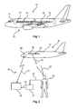
- Fig. 1 shows an aircraft 10, comprising a fuselage structure 12 and a wing structure 14 attached to the fuselage structure 12.
- At least one multifunctional light unit 16 is provided, comprising at least one light source 18 for outboard light emission.
- the multifunctional light unit 16 is provided on sideway facing areas, such as sideway areas 20 of the fuselage structure 12.
- the sideway facing areas comprise lateral sideway facing surface areas and/or forward and backwards facing surface areas.
- the sideway areas 20 comprise lateral sideway surface areas 22, and/or nose-tip sideway areas 24 of the fuselage structure 12.
- the at least one multifunctional light unit 16 is configured to provide at least one of the group of: i) directional signalling of the aircraft, relating to at least one of the group of movement of the aircraft in an airborne state, and movement of the aircraft in an on-ground state; ii) status signalling of the aircraft, relating to at least one of the group of status of the aircraft, status of the current flight mission, and status of the traffic situation; and iii) identification signalling of the aircraft, relating to at least one of the group of type and specific model of the aircraft, operating airline, flight number, and origin and destination.
- directional signalling the "status signalling”
- identification signalling it is kindly referred to the respective descriptions above, which is also applicable for the embodiments shown in the figures.
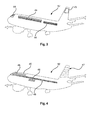
- Fig. 2 shows an example, where the sideway facing areas of the aircraft, e.g. the sideway areas 20 of the fuselage structure 12, with the at least one multifunctional light unit 16 provide an adaptable graphical user interface 26 as a communication interface of a human-machine-interface 28 of the aircraft for providing information exchange between the aircraft and a user located outside the aircraft.
- the sideway facing areas of the aircraft e.g. the sideway areas 20 of the fuselage structure 12
- the at least one multifunctional light unit 16 provide an adaptable graphical user interface 26 as a communication interface of a human-machine-interface 28 of the aircraft for providing information exchange between the aircraft and a user located outside the aircraft.
- the sideway facing areas of the aircraft comprise window areas of the fuselage structure.
- the window areas comprise cabin and/or cockpit windows and areas between adjacent windows and adjacent areas below and above the windows.
- the multifunctional light unit 16 provides visual information, indicated with a first arrow 30, which is then perceived by a user 32, wherein the information perception by the user is indicated with a fan-like structure 33.
- the user 32 can provide commands or control functions or instructions to a user interface 34, wherein a second arrow 36 indicates the provision of the respective commands or instructions.
- the user interface 34 is connected to a control unit 36 and provides the respective data via a first data connection 38.
- the control unit 36 is in communicating connection, indicated by an arrow 40, with an onboard control unit 42 of the aircraft 10.
- the user 32 receives certain travelling indication information, for example provided by the pilots in the cockpit via the multifunctional light unit(s), and the user 32 can then give a feedback via the communication connection 40 to the control unit 42 onboard the aircraft, providing the respective information to the pilots.
- certain travelling indication information for example provided by the pilots in the cockpit via the multifunctional light unit(s)
- the user 32 can then give a feedback via the communication connection 40 to the control unit 42 onboard the aircraft, providing the respective information to the pilots.
- the human-machine-interface 28 may have more than one user watching the aircraft and perceiving the information.
- operating staff such as pilots are users when activating the multifunctional light units are users, even when sitting inside the aircraft.
- multifunctional light units are provided on board of unmanned aircraft for providing the above described signalling.
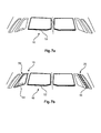
- Fig. 3 shows the aircraft outline with dotted lines indicating a reduced or poor visibility of the aircraft itself, for example in dark environments such as during night or evening hours.
- Fig. 4 shows the aircraft outline with dotted lines indicating a reduced or poor visibility of the aircraft itself, for example in dark environments such as during night or evening hours.
- additional information is provided to the outside.
- Fig. 3 shows a further example of an aircraft, wherein as the multifunctional light units 16, lighting surface areas 44 are provided on the outside of the fuselage structure 12.
- they can be provided above a window arrangement, as shown in the front part of the fuselage, i.e. in the left half of the image, or between windows, as shown in the rear part, or right part of the drawing.
- the lighting surface areas 44 are provided below the windows.
- the lighting surface areas can also be provided in the nose tip area of the aircraft.
- the lighting surface areas 44 are provided as organic light-emitting diodes, for example provided below a light-transmissive outer cover layer.
- Lighting surface areas 45 may also be provided in the tail portion of the aircraft, e.g. on the vertical stabilizer, for example alternative or in addition to the arrangement on the fuselage.
- Fig. 4 shows a further example of the aircraft 12, wherein as multifunctional light units 16, a plurality of lighting spots 46 is provided, distributed across surface areas of the fuselage.
- the lighting spots are provided as LEDs inserted in the outer skin, for example below a protective light-transmissive cover layer.
- the LEDs can be provided in small holes in the outer skin material, and thus be combined to provide the effect of a light surface area.
- Lighting spots 47 may also be provided in the tail portion of the aircraft, e.g. on the vertical stabilizer, for example alternative or in addition to the arrangement on the fuselage.
- Fig. 5 shows a further example of the aircraft 12, wherein the fuselage structure 12 is provided with a plurality of 48 of windows 50. At least one of the windows is provided with the at least one multifunctional light unit 16. For example, as shown, all cabin windows, as well as the cockpit window, are equipped with the multifunctional light unit 16. Of course, a reduced number of windows are equipped with multifunctional light units 16 in another example (not shown). Further, the fuselage structure 12 is provided with one or more doors, and one or more of the doors is provided with one or more multifunctional light units 16.
- Fig. 5 shows the multifunctional light units providing status signalling of the aircraft, as described above.
- the status can be a colour code, a blinking code or an illumination-blinking code.
- Fig. 6 shows a further example where the multifunctional light units provide identification signalling of the aircraft, as described above.
- the multifunctional light units 16 provide directional signalling, as described above.
- the illumination of lower contour lines 52 of the front cockpit windows may provide a socalled signature signalling to indicate corporate identity.
- the illumination of lower contour lines 52 of the front cockpit windows may also indicate one before-mentioned signalling, i.e. directional signalling, status signalling, and identification signalling, for example movement indication information.
- the example in Fig. 7B shows further possibilities to provide directional signalling, or other signalling, for example by flashing the starboard side cockpit window, i.e. the respective outline or contour in a first colour 54, for example in green, while the respective counterpart, i.e.
- Fig. 7A and Fig. 7B show a section of a front view of an aircraft where only the cockpit window area is shown.
- the at least one multifunctional light unit 16 is provided following at least a part of a contour 58 of the respective window. For example, this is provided for cabin windows, and/or for cockpit windows, as shown in Figs. 7A and 7B .
- sideway areas comprises the portions of a fuselage that are facing in a direction which has at least a small horizontal component in its orientation, for example with an inclination f at least +/- 15° from the horizontal plane, when the aircraft is in its normal parking position on a horizontal airfield, for example.
- the sideway areas not only comprise windows of the cabin facing to port and starboard, but also cockpit windows facing to front port and front starboard. Further, the sideway areas also comprise cockpit windows facing in the flight direction, i.e. facing approximately in the longitudinal direction of the aircraft, such as the tow middle or centre windows of Figs. 7A and 7B . In case of cabin space located in the aircraft's front end, similar is the case for cabin windows facing in directions similar as cockpit windows.
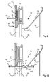
- the multifunctional light unit 16 is integrated in a window construction, and there may be provided different positioning of the light source in relation to the windowpanes.
- the cross-section shown in Fig. 8A, 8B and 8C shows an outer windowpane 60 on the left, followed by a further windowpane 64.
- the outer windowpane 60 is provided to withstand the pressure difference between the cabin and the outside environment and to provide protection from the environmental conditions in form of, for example, rain and moisture, besides the low pressure.
- the outer windowpane 60 and the further windowpane 64 provide an insulating effect by enclosing an intermediate space. For pressure compensation, a little hole in the further windowpane 64 may be arranged.
- the two windowpanes 60, 64 are followed by a further third windowpane 66 facing towards the cabin, acting as a protection pane for the second windowpane 64.
- the windowpanes are connected to a frame 68, which is mounted to the outer skin 70 and thus the fuselage structure.
- a window funnel 72 is provided with an increasing opening size in direction of the cabin space.
- a further cover or sealing part 74 is provided, for example as a continuation of the funnel 72.
- the light source 18 is provided behind the outer windowpane 60.
- the light source provided integrated in the window construction may also serve as a source for thermal energy for reducing the formation of condensate on the surfaces of the middle pane or on the surface of the inner pane facing away from the cabin, also known as foggy or iced windows. Even a small amount of heat generation by a light source may be sufficient to allow a higher degree of relative humidity in the cabin space.
- the "heat" provided by the light source is used to warm up the air between the windowpanes.
- the light source for example light emitting diodes (LEDs), or other suitable light sources, may be provided integrated within the window setup, for example integrated between the outer and middle windowpane.
- LEDs light emitting diodes
- the light source may be provided integrated within one of the windowpanes, for example integrated in the outer or middle windowpane.
- the light source may be at least partly inserted in the windowpane element.
- the light source is completely inserted in the windowpane element.
- the light source is fully integrated by providing the electronic circuitry during the production of the windowpane. For example, before molding the windowpane, at least one LED circuitry is provided without the usual embedding structure forming housing and lens structure, but the windowpane is provided as mass encapsulating the circuitry and thus forming housing or body structure of an LED. Thus, a windowpane made from a homogenous material can be provided.
- the light source may be provided integrated within a window frame portion.
- Fig. 8A shows the light source 18 as a circle as an abstract indication of a light source.
- the light source may of course have different forms, such as light bulbs, light tubes, light rings, LEDs, LED arrays and the like. Further, optics or optical elements such as lenses, grids, reflectors and the like, may be provided in addition to the light source (not shown in detail).
- the at least one light source 18 is provided behind the further, or middle windowpane 64, wherein the at least one light source 16 is provided in a circumferential frame area 62.
- the light source 18 is provided integrated behind the funnel 72.
- the sealing part 74 may connect the funnel 72 with a light convey barricade 76, which can be provided optionally.
- the light convey barricade 76 serves for light reflection to prevent light from the multifunctional light unit being reflected towards the passenger.
- the light convey barricade 76 may be provided as holographic structure in the windowpane panel element. Also, other optically effective structures may be provided such as change in material properties to provide a differing refraction index.
- reflector means 78 are provided in the vicinity of the light source 18. The reflectors, such as the reflector means 78 or the light convey barricade 76, are provided for preventing inboard light emission.
- a sealing for example an elastic sealing is provided between the outer and the middle windowpane, for example for preventing unwanted back reflection of signalling light towards the passenger.
- An arrow 80 indicates outdoor light emission through the second windowpane 64 and the outer, i.e. first windowpane 60.
- the at least one light source 18 is provided integrated in the middle windowpane 64.
- an LED array 81 is provided.
- an LED array is provided between the outer windowpane 60 and the middle windowpane 64.
- a diffuser can be provided in the vicinity of the outer covering pane, for example on the inside of the outer window 60 (not shown in detail).
- the at least one light source 18 is provided integrated inside the outer windowpane 60.
- the pane can be provided with a slightly increased thickness to allow an at least partial insertion of LEDs of an LED array 83 into the window/glazing element. LEDs can be configured to provide light emission in different directions 85, for example as directed light bundles or as diffuse light emission.
- the inner windowpane is provided with a filtering effect for a selected light wavelength range, such as a filter layer on the side facing away from the passenger.
- the middle windowpane is provided with a filtering effect, depending on the location of the light source.
- the multifunctional light units provide visual signalling in a predetermined wavelength range. In case of light being reflected by the outer or middle window, this particular light spectrum is filtered by the inner windowpane. Thus, the signalling light is not visible to the passenger inside the cabin.
- the filtering effect of the window may also be used for providing certain coloured ambient light in the cabin, since the light spectrum is somewhat manipulated by the filter effect. For example, red light spectrum is used for the signalling, and the filter effect leads to a blue(r) ambient cabin light provided by the daylight entry through the window.
- the inner windowpane (and/or middle windowpane) is provided with a selective reflecting effect, or selective reflection and thus also filtering effect for a selected light wavelength range.
- a light source can provide light with a predetermined light spectrum.
- a geometrically small, but powerful, light source emits light onto the windowpane which reflects the light to the outside of the aircraft, thus providing a geometrically larger light emitting area.
- the light source emits light in a predetermined range not only to a selectively reflective layer, but also directly towards the exterior to be directly visible.
- the light source is arranged such that it can be seen by the passenger.
- the light generated is provided as invisible light waves, wherein "visible” relates to the visibility by a human eye.
- a conversion device is provided, where the invisible light waves are transformed into signalling light visible from the outside of the aircraft. Hence, visible light is emitted.
- the conversion device is arranged such that the visible light, which is provided by the conversion device, is not visible to the passenger inside the cabin.
- the conversion device may be a reflecting coating on the outer surface of a windowpane, such as the middle or inner windowpane.
- a first window area 87 is provided where the window itself is visible, as well as a second window area 89 where the window itself is not visible.
- a separating line 91 is shown for further illustration. It is noted that the separation of course also depends on the user's viewpoint or position. Nevertheless, in the first window area, the construction is hidden from direct view by the user.
- the light source of the multifunctional light unit may be provided in this first window, i.e. in the window covered by the first window area, such that the light emission is not visible from the inside of the cabin.
- additional measurements may be provided for preventing any unwanted light mission towards a passenger in the cabin, or a pilot in the cockpit.
- the transparent windowpanes may be made of glass material or plastic material, such as acrylic glass, also known under the trademark Plexiglas.
- an example is provided with an intermediate frame structure 94 between the fuselage structure 12 and a window frame 96.
- the multifunctional light unit 16, i.e. the light source 18 is provided in the intermediate frame structure 94.
- a light source is provided protected by a cover.
- a layer comprising OLED structures is provided on the intermediate frame structure 94.
- the OLED may be provided on one or more side portions (left/right/top/bottom) of the window, or may be provided circumferentially, thus tracing the window's shape.
- a protection cover may be arranged on the OLED structure.
- a layer comprising OLED structures is provided on the frame 68.
- a layer comprising OLED structures is provided on the fuselage's outer skin, for example as graphic elements surrounding the window, i.e. window frame.
- the multifunctional light unit 16 provides also inboard light emission for cabin lighting.
- At least one primary light source 98 is provided, and at least one secondary light source 100.
- the primary light source 98 provides the outboard light emission 80.
- the secondary light source 100 provides inboard light emission 102.
- the primary and the secondary light sources 98, 110 may be provided to be controllable individually.
- a control unit is provided to activate at least one parameter of the group of light colour, light brightness, light intensity, flashing frequency, or blinking frequency.
- Fig. 11 shows a functional diagram together with the above described cross-section.
- the light source 18 is provided with an internal/external controller 82.
- a power supply 84 may be provided, for example by the aircraft cabin systems.
- a solar collector 86 may be connected to the controller 82.
- a communication frame 88 indicates the wire and/or wireless technology to affected aircraft systems, for example the cockpit and/or the cabin.
- an energy storage 90 may be provided.
- an optical sensor for daylight detection may be provided, as indicated with a further frame 92. It must be noted that although Fig. 11 shows a particular embodiment for the light source, also other embodiments of the light source, e.g. according to one of the above-described examples, are provided in combination with the components shown in Fig. 11 .
- Fig. 12 shows a perspective view of a cabin window with an integrated multifunctional light unit.
- a photovoltaic element 104 may be provided integrated in the window construction for energy supply of the multifunctional light unit, the latter being hidden behind the light convey barricade 76.
- the photovoltaic element is provided on the window funnel 72, for example in the lower portions, or is provided on the rear side of a blind or window shade 106.
- Fig. 13 shows schematic setups for allowing different visualizations of directional signalling, status signalling, or identification signalling.
- Fig. 13A shows a first embodiment with a light band 108, for example following the contour of a window. Further, light points 110 are shown in the corner portions of the window.
- Fig. 13B shows the light band 108 with a separate portion 112, for example on the left vertical part. Further, the light points 110 are provided as first light points 110a in a first colour and second light points 110b in a second colour.
- Fig. 13C shows an example of a light band 108 with different, i.e. individual light band segments, for example segments 108a to 108h.
- Fig. 14 shows a perspective view of a tail portion of an aircraft.
- light projections 114 are provided, such as a light projection 114a on the fuselage 12 and/or a light projection 114b on the tail portion, i.e. on a vertical stabilizer 116.
- the light projections 114 are generated by projecting devices 118 located such that the light can be projected onto reflecting surfaces on the aircraft.
- projecting devices 118a are provided integrated into a wing's outer skin on the upper side, and/or as projecting devices 118b integrated into the horizontal stabilizer's outer skin on the upper side.
- the projecting devices 118 may comprise a lens or lens system or other optical systems.
- the light projection provides one or more of the before-mentioned signalling, i.e. directional signalling, status signalling, and identification signalling.
- Fig. 15 shows a method 200 for providing visual signalling of an aircraft, comprising the following steps:
- a first step 210 at least one multifunctional light unit is activated, wherein the at least one multifunctional light unit is provided according to one of the above mentioned examples.
- a second step 212 is provided at least one of the group of the following signalling:
- a first sub-step 214 directional signalling of the aircraft is provided, relating to at least one of the group of movement of the aircraft in an airborne state, and movement of the aircraft in an on-ground state.
- status signalling of the aircraft is provided, relating to at least one of the group of status of the aircraft, status of the current flight mission, and status of the traffic situation.
- identification signalling of the aircraft is provided, relating to at least one of the group of: type and specific model of the aircraft, operating airline, flight number, and origin/destination.
- the first step 210 is also referred to as step a), and the second step 212 as step b).
- the first sub-step 214 is also referred to as step b1), the second sub-step 216 as step b2), and the third sub-step 218 as step b3).
- the three sub-steps 214, 216, 218 can be provided alternatively or in addition to each other in various combinations.
- the substeps may also be provided at different times, same times or overlapping time intervals.
Landscapes
- Engineering & Computer Science (AREA)
- Aviation & Aerospace Engineering (AREA)
- Physics & Mathematics (AREA)
- General Physics & Mathematics (AREA)
- Traffic Control Systems (AREA)
Priority Applications (5)
| Application Number | Priority Date | Filing Date | Title |
|---|---|---|---|
| EP12188236.9A EP2719625A1 (de) | 2012-10-11 | 2012-10-11 | Visuelle Signalgebung eines Flugzeugs |
| EP13776776.0A EP2906472B1 (de) | 2012-10-11 | 2013-10-10 | Visuelle signalgebung eines flugzeugs |
| US14/434,902 US9950811B2 (en) | 2012-10-11 | 2013-10-10 | Visual signalling of an aircraft |
| CN201380053220.4A CN104718134B (zh) | 2012-10-11 | 2013-10-10 | 飞行器的可视信令 |
| PCT/EP2013/071165 WO2014057037A1 (en) | 2012-10-11 | 2013-10-10 | Visual signalling of an aircraft |
Applications Claiming Priority (1)
| Application Number | Priority Date | Filing Date | Title |
|---|---|---|---|
| EP12188236.9A EP2719625A1 (de) | 2012-10-11 | 2012-10-11 | Visuelle Signalgebung eines Flugzeugs |
Publications (1)
| Publication Number | Publication Date |
|---|---|
| EP2719625A1 true EP2719625A1 (de) | 2014-04-16 |
Family
ID=47080308
Family Applications (2)
| Application Number | Title | Priority Date | Filing Date |
|---|---|---|---|
| EP12188236.9A Withdrawn EP2719625A1 (de) | 2012-10-11 | 2012-10-11 | Visuelle Signalgebung eines Flugzeugs |
| EP13776776.0A Active EP2906472B1 (de) | 2012-10-11 | 2013-10-10 | Visuelle signalgebung eines flugzeugs |
Family Applications After (1)
| Application Number | Title | Priority Date | Filing Date |
|---|---|---|---|
| EP13776776.0A Active EP2906472B1 (de) | 2012-10-11 | 2013-10-10 | Visuelle signalgebung eines flugzeugs |
Country Status (4)
| Country | Link |
|---|---|
| US (1) | US9950811B2 (de) |
| EP (2) | EP2719625A1 (de) |
| CN (1) | CN104718134B (de) |
| WO (1) | WO2014057037A1 (de) |
Cited By (3)
| Publication number | Priority date | Publication date | Assignee | Title |
|---|---|---|---|---|
| EP3106392A1 (de) * | 2015-06-19 | 2016-12-21 | Goodrich Lighting Systems GmbH | Beleuchtungslichteinheit für ein flugzeugseitenleitwerk und verfahren zum betrieb einer beleuchtungslichteinheit für ein flugzeugseitenleitwerk |
| GB2553524A (en) * | 2016-09-06 | 2018-03-14 | Airbus Operations Ltd | Wing tip device |
| EP3812283A1 (de) * | 2019-10-22 | 2021-04-28 | Goodrich Lighting Systems GmbH | Flugzeugbildprojektor für aussenbereich |
Families Citing this family (22)
| Publication number | Priority date | Publication date | Assignee | Title |
|---|---|---|---|---|
| ES2728298T3 (es) * | 2014-10-02 | 2019-10-23 | Goodrich Lighting Systems Gmbh | Unidad de iluminación de aeronaves para la iluminación en tierra y aeronaves que comprenden la misma |
| US9558674B2 (en) * | 2015-04-07 | 2017-01-31 | Honeywell International Inc. | Aircraft systems and methods to display enhanced runway lighting |
| GB2538317A (en) * | 2015-05-15 | 2016-11-16 | Rees Williams David | Safety system |
| US10156627B2 (en) * | 2015-10-15 | 2018-12-18 | uAvionix Corporation | Aircraft navigation light ADS-B radio |
| CN105217050A (zh) * | 2015-10-27 | 2016-01-06 | 杨珊珊 | 一种便于观察的无人飞行器 |
| CN107085433B (zh) * | 2016-02-16 | 2021-08-10 | 松下电器(美国)知识产权公司 | 发光控制装置、无人飞行器、以及发光控制方法 |
| WO2017174119A1 (de) * | 2016-04-05 | 2017-10-12 | Airbus Operations Gmbh | Nachrüstbare anzeigeeinrichtung zum anzeigen eines aktivierungsstatus einer notrutsche in einem flugzeug |
| EP3335997B1 (de) * | 2016-12-18 | 2019-11-06 | Goodrich Lighting Systems GmbH | Verfahren zum betrieb eines flugzeugscheinwerfersystems, flugzeugscheinwerfersystem und flugzeug mit einem solchen system |
| US10053006B1 (en) * | 2017-01-31 | 2018-08-21 | Ford Global Technologies, Llc | Illuminated assembly |
| US20200017236A1 (en) * | 2017-02-16 | 2020-01-16 | Benjamin Scheidler | Arrangement for projections onto the exterior surf ace of an aircraft |
| EP3403936B1 (de) * | 2017-05-19 | 2021-07-14 | Goodrich Lighting Systems GmbH | Kombinierte start- und towersignallichteinheit für ein flugzeug und flugzeug damit |
| JP2019085104A (ja) * | 2017-11-06 | 2019-06-06 | 株式会社エアロネクスト | 飛行体及び飛行体の制御方法 |
| CN109905169A (zh) * | 2017-12-11 | 2019-06-18 | 上海航空电器有限公司 | 一种光通信机载数据加下载系统 |
| US10450082B1 (en) * | 2018-05-07 | 2019-10-22 | The Boeing Company | Sensor-based guidance for rotorcraft |
| US10532825B2 (en) | 2018-05-07 | 2020-01-14 | The Boeing Company | Sensor-based guidance for rotorcraft |
| US10604273B2 (en) | 2018-07-30 | 2020-03-31 | Honeywell International Inc. | Aircraft lighting system for informing trailing aircraft |
| EP3626630B1 (de) * | 2018-09-21 | 2023-06-07 | Goodrich Lighting Systems GmbH | Flugzeugaussenleuchte, flugzeugflügel damit und verfahren zum betrieb einer flugzeugaussenleuchte |
| EP3626631B1 (de) | 2018-09-21 | 2021-09-01 | Goodrich Lighting Systems GmbH | Luftfahrzeugleuchte für eine klappbare flügelspitze, luftfahrzeug mit und verfahren zum betreiben einer solchen leuchte |
| FR3092387B1 (fr) * | 2019-01-31 | 2021-01-15 | Airbus Helicopters | Système d’éclairage directionnel équipant un aéronef et procédé d’éclairage associé |
| US10549866B1 (en) * | 2019-02-19 | 2020-02-04 | Goodrich Lighting Systems | Position lights as direction change signals |
| KR102567249B1 (ko) * | 2021-04-21 | 2023-08-21 | (주)안세기술 | 3차원 레이저 스캐너를 이용한 항공기 주기유도 시스템 및 이를 이용한 항공기 주기 제어방법 |
| FR3135969A1 (fr) | 2022-05-30 | 2023-12-01 | Airbus Helicopters | Aéronef muni d’un système d’avertissement holographique |
Citations (4)
| Publication number | Priority date | Publication date | Assignee | Title |
|---|---|---|---|---|
| US4916445A (en) * | 1988-11-09 | 1990-04-10 | Crossley Simon M | Obstruction proximity indication system for an aircraft |
| US5813744A (en) * | 1997-03-17 | 1998-09-29 | Mcdonnell Douglas Corp. | Aircraft ground floodlight |
| JP2002341432A (ja) * | 2001-05-16 | 2002-11-27 | Murakami Corp | 撮像装置 |
| US20080048101A1 (en) * | 2005-12-15 | 2008-02-28 | The Boeing Company | Systems and methods for controlling windows with variable light transmission |
Family Cites Families (13)
| Publication number | Priority date | Publication date | Assignee | Title |
|---|---|---|---|---|
| US3411131A (en) * | 1965-10-05 | 1968-11-12 | Aero Safety Devices Inc | Emergency exit signal device for aircraft |
| US4299442A (en) | 1980-04-14 | 1981-11-10 | Buckelew Arthur L | Aircraft visual collision and avoidance device |
| US6846099B2 (en) * | 2001-06-21 | 2005-01-25 | Honeywell International Inc. | Aircraft position light |
| US6909544B2 (en) * | 2002-04-16 | 2005-06-21 | Honeywell International Inc. | Method for eliminating strong ambient light in aircraft cockpits |
| US7596899B1 (en) * | 2004-09-27 | 2009-10-06 | Welshmark Industries Inc. | Flexible releasably-mounted display device |
| US7095318B1 (en) * | 2004-09-28 | 2006-08-22 | Solomon Bekhor | Enhanced vehicle advisory system to advise drivers of other vehicles and passengers in the vehicle of actions taken by the driver |
| WO2008019105A2 (en) * | 2006-08-03 | 2008-02-14 | Lanham Randall J | Video display screen systems and methods for displaying information |
| US8096069B2 (en) * | 2006-09-06 | 2012-01-17 | The Invention Science Fund I, Llc | Repeatably displaceable emanating element display |
| FR2932159B1 (fr) * | 2008-06-05 | 2010-07-30 | Airbus France | Rampe d'eclairage pour aeronef |
| NZ591453A (en) * | 2008-09-02 | 2013-09-27 | Concept Ideas Pty Ltd | Arrangement for illuminating an aircraft fuselage |
| US8876295B2 (en) * | 2008-10-01 | 2014-11-04 | The United States Of America As Represented By The Secretary Of The Army | Method for displaying images and/or other information on aircraft blades |
| CN102121661B (zh) * | 2010-12-20 | 2013-05-29 | 中国商用飞机有限责任公司 | 一种用于航行灯的反射面罩以及使用该反射面罩的航行灯 |
| US8933819B1 (en) * | 2012-09-04 | 2015-01-13 | The Boeing Company | Exterior aircraft display system |
-
2012
- 2012-10-11 EP EP12188236.9A patent/EP2719625A1/de not_active Withdrawn
-
2013
- 2013-10-10 US US14/434,902 patent/US9950811B2/en active Active
- 2013-10-10 CN CN201380053220.4A patent/CN104718134B/zh active Active
- 2013-10-10 WO PCT/EP2013/071165 patent/WO2014057037A1/en active Application Filing
- 2013-10-10 EP EP13776776.0A patent/EP2906472B1/de active Active
Patent Citations (4)
| Publication number | Priority date | Publication date | Assignee | Title |
|---|---|---|---|---|
| US4916445A (en) * | 1988-11-09 | 1990-04-10 | Crossley Simon M | Obstruction proximity indication system for an aircraft |
| US5813744A (en) * | 1997-03-17 | 1998-09-29 | Mcdonnell Douglas Corp. | Aircraft ground floodlight |
| JP2002341432A (ja) * | 2001-05-16 | 2002-11-27 | Murakami Corp | 撮像装置 |
| US20080048101A1 (en) * | 2005-12-15 | 2008-02-28 | The Boeing Company | Systems and methods for controlling windows with variable light transmission |
Cited By (5)
| Publication number | Priority date | Publication date | Assignee | Title |
|---|---|---|---|---|
| EP3106392A1 (de) * | 2015-06-19 | 2016-12-21 | Goodrich Lighting Systems GmbH | Beleuchtungslichteinheit für ein flugzeugseitenleitwerk und verfahren zum betrieb einer beleuchtungslichteinheit für ein flugzeugseitenleitwerk |
| US10336468B2 (en) | 2015-06-19 | 2019-07-02 | Goodrich Lighting Systems Gmbh | Aircraft vertical stabilizer illumination light unit and method of operating an aircraft vertical stabilizer illumination light unit |
| GB2553524A (en) * | 2016-09-06 | 2018-03-14 | Airbus Operations Ltd | Wing tip device |
| EP3812283A1 (de) * | 2019-10-22 | 2021-04-28 | Goodrich Lighting Systems GmbH | Flugzeugbildprojektor für aussenbereich |
| US11465772B2 (en) | 2019-10-22 | 2022-10-11 | Goodrich Lighting Systems Gmbh | Exterior aircraft image projector |
Also Published As
| Publication number | Publication date |
|---|---|
| CN104718134A (zh) | 2015-06-17 |
| EP2906472B1 (de) | 2019-05-22 |
| WO2014057037A1 (en) | 2014-04-17 |
| CN104718134B (zh) | 2018-02-23 |
| US9950811B2 (en) | 2018-04-24 |
| US20150232198A1 (en) | 2015-08-20 |
| EP2906472A1 (de) | 2015-08-19 |
Similar Documents
| Publication | Publication Date | Title |
|---|---|---|
| EP2906472B1 (de) | Visuelle signalgebung eines flugzeugs | |
| CN107757936B (zh) | 外部飞机灯单元和警示地面人员的方法 | |
| ES2966885T3 (es) | Procedimiento y sistema de visualización del entorno exterior de un avión así como puerta de avión equipada con tal sistema | |
| ES2728298T3 (es) | Unidad de iluminación de aeronaves para la iluminación en tierra y aeronaves que comprenden la misma | |
| US11097855B2 (en) | Aircraft beacon light and aircraft comprising an aircraft beacon light | |
| US11465773B2 (en) | Aircraft beacon light unit and set of aircraft beacon light units | |
| US20180000062A1 (en) | Aircraft lighting system | |
| US20200017236A1 (en) | Arrangement for projections onto the exterior surf ace of an aircraft | |
| US10836506B2 (en) | Exterior aircraft light, aircraft wing comprising the same, and method of operating an exterior aircraft light | |
| BR102017002036B1 (pt) | Conjunto de localização de cabine de veículo e método de direcionamento eficiente de passageiros a bordo de um veículo | |
| US8245973B2 (en) | Methods and systems for improving aircraft visibility | |
| US11260989B2 (en) | Aircraft beacon light, aircraft wing, aircraft beacon light system, and method of supplementing an aircraft beacon light system | |
| US20190241278A1 (en) | Helicopter and window lights | |
| GB2540665A (en) | Aircraft landing gear drive wheel identification system | |
| US11465772B2 (en) | Exterior aircraft image projector | |
| KR101775975B1 (ko) | 탑승교의 출입문 위치 표시 장치 | |
| US20090303084A1 (en) | Method and apparatus for providing visible indication of elevated airport light color | |
| CN108966454B (zh) | 一种基于光路提示的航空障碍灯系统 | |
| CN116022374A (zh) | 一种用于无人机智能运行的光学交互系统 |
Legal Events
| Date | Code | Title | Description |
|---|---|---|---|
| PUAI | Public reference made under article 153(3) epc to a published international application that has entered the european phase |
Free format text: ORIGINAL CODE: 0009012 |
|
| AK | Designated contracting states |
Kind code of ref document: A1 Designated state(s): AL AT BE BG CH CY CZ DE DK EE ES FI FR GB GR HR HU IE IS IT LI LT LU LV MC MK MT NL NO PL PT RO RS SE SI SK SM TR |
|
| AX | Request for extension of the european patent |
Extension state: BA ME |
|
| STAA | Information on the status of an ep patent application or granted ep patent |
Free format text: STATUS: THE APPLICATION IS DEEMED TO BE WITHDRAWN |
|
| 18D | Application deemed to be withdrawn |
Effective date: 20141017 |