EP2719566B1 - Befüllkopf für einen Flüssigkeitstank - Google Patents
Befüllkopf für einen Flüssigkeitstank Download PDFInfo
- Publication number
- EP2719566B1 EP2719566B1 EP13176134.8A EP13176134A EP2719566B1 EP 2719566 B1 EP2719566 B1 EP 2719566B1 EP 13176134 A EP13176134 A EP 13176134A EP 2719566 B1 EP2719566 B1 EP 2719566B1
- Authority
- EP
- European Patent Office
- Prior art keywords
- sealing element
- filling head
- filling
- filler neck
- moulded part
- Prior art date
- Legal status (The legal status is an assumption and is not a legal conclusion. Google has not performed a legal analysis and makes no representation as to the accuracy of the status listed.)
- Active
Links
Images


Classifications
-
- B—PERFORMING OPERATIONS; TRANSPORTING
- B60—VEHICLES IN GENERAL
- B60K—ARRANGEMENT OR MOUNTING OF PROPULSION UNITS OR OF TRANSMISSIONS IN VEHICLES; ARRANGEMENT OR MOUNTING OF PLURAL DIVERSE PRIME-MOVERS IN VEHICLES; AUXILIARY DRIVES FOR VEHICLES; INSTRUMENTATION OR DASHBOARDS FOR VEHICLES; ARRANGEMENTS IN CONNECTION WITH COOLING, AIR INTAKE, GAS EXHAUST OR FUEL SUPPLY OF PROPULSION UNITS IN VEHICLES
- B60K15/00—Arrangement in connection with fuel supply of combustion engines or other fuel consuming energy converters, e.g. fuel cells; Mounting or construction of fuel tanks
- B60K15/03—Fuel tanks
- B60K15/035—Fuel tanks characterised by venting means
-
- B—PERFORMING OPERATIONS; TRANSPORTING
- B60—VEHICLES IN GENERAL
- B60K—ARRANGEMENT OR MOUNTING OF PROPULSION UNITS OR OF TRANSMISSIONS IN VEHICLES; ARRANGEMENT OR MOUNTING OF PLURAL DIVERSE PRIME-MOVERS IN VEHICLES; AUXILIARY DRIVES FOR VEHICLES; INSTRUMENTATION OR DASHBOARDS FOR VEHICLES; ARRANGEMENTS IN CONNECTION WITH COOLING, AIR INTAKE, GAS EXHAUST OR FUEL SUPPLY OF PROPULSION UNITS IN VEHICLES
- B60K15/00—Arrangement in connection with fuel supply of combustion engines or other fuel consuming energy converters, e.g. fuel cells; Mounting or construction of fuel tanks
- B60K15/03—Fuel tanks
- B60K15/04—Tank inlets
-
- B—PERFORMING OPERATIONS; TRANSPORTING
- B60—VEHICLES IN GENERAL
- B60K—ARRANGEMENT OR MOUNTING OF PROPULSION UNITS OR OF TRANSMISSIONS IN VEHICLES; ARRANGEMENT OR MOUNTING OF PLURAL DIVERSE PRIME-MOVERS IN VEHICLES; AUXILIARY DRIVES FOR VEHICLES; INSTRUMENTATION OR DASHBOARDS FOR VEHICLES; ARRANGEMENTS IN CONNECTION WITH COOLING, AIR INTAKE, GAS EXHAUST OR FUEL SUPPLY OF PROPULSION UNITS IN VEHICLES
- B60K15/00—Arrangement in connection with fuel supply of combustion engines or other fuel consuming energy converters, e.g. fuel cells; Mounting or construction of fuel tanks
- B60K15/03—Fuel tanks
- B60K2015/03256—Fuel tanks characterised by special valves, the mounting thereof
- B60K2015/03289—Float valves; Floats therefor
-
- B—PERFORMING OPERATIONS; TRANSPORTING
- B60—VEHICLES IN GENERAL
- B60K—ARRANGEMENT OR MOUNTING OF PROPULSION UNITS OR OF TRANSMISSIONS IN VEHICLES; ARRANGEMENT OR MOUNTING OF PLURAL DIVERSE PRIME-MOVERS IN VEHICLES; AUXILIARY DRIVES FOR VEHICLES; INSTRUMENTATION OR DASHBOARDS FOR VEHICLES; ARRANGEMENTS IN CONNECTION WITH COOLING, AIR INTAKE, GAS EXHAUST OR FUEL SUPPLY OF PROPULSION UNITS IN VEHICLES
- B60K15/00—Arrangement in connection with fuel supply of combustion engines or other fuel consuming energy converters, e.g. fuel cells; Mounting or construction of fuel tanks
- B60K15/03—Fuel tanks
- B60K2015/03309—Tanks specially adapted for particular fuels
-
- B—PERFORMING OPERATIONS; TRANSPORTING
- B60—VEHICLES IN GENERAL
- B60K—ARRANGEMENT OR MOUNTING OF PROPULSION UNITS OR OF TRANSMISSIONS IN VEHICLES; ARRANGEMENT OR MOUNTING OF PLURAL DIVERSE PRIME-MOVERS IN VEHICLES; AUXILIARY DRIVES FOR VEHICLES; INSTRUMENTATION OR DASHBOARDS FOR VEHICLES; ARRANGEMENTS IN CONNECTION WITH COOLING, AIR INTAKE, GAS EXHAUST OR FUEL SUPPLY OF PROPULSION UNITS IN VEHICLES
- B60K15/00—Arrangement in connection with fuel supply of combustion engines or other fuel consuming energy converters, e.g. fuel cells; Mounting or construction of fuel tanks
- B60K15/03—Fuel tanks
- B60K2015/03328—Arrangements or special measures related to fuel tanks or fuel handling
- B60K2015/03348—Arrangements or special measures related to fuel tanks or fuel handling for supplying additives to fuel
-
- B—PERFORMING OPERATIONS; TRANSPORTING
- B60—VEHICLES IN GENERAL
- B60K—ARRANGEMENT OR MOUNTING OF PROPULSION UNITS OR OF TRANSMISSIONS IN VEHICLES; ARRANGEMENT OR MOUNTING OF PLURAL DIVERSE PRIME-MOVERS IN VEHICLES; AUXILIARY DRIVES FOR VEHICLES; INSTRUMENTATION OR DASHBOARDS FOR VEHICLES; ARRANGEMENTS IN CONNECTION WITH COOLING, AIR INTAKE, GAS EXHAUST OR FUEL SUPPLY OF PROPULSION UNITS IN VEHICLES
- B60K15/00—Arrangement in connection with fuel supply of combustion engines or other fuel consuming energy converters, e.g. fuel cells; Mounting or construction of fuel tanks
- B60K15/03—Fuel tanks
- B60K2015/03328—Arrangements or special measures related to fuel tanks or fuel handling
- B60K2015/03368—Arrangements or special measures related to fuel tanks or fuel handling for preventing overfilling of tanks
-
- B—PERFORMING OPERATIONS; TRANSPORTING
- B60—VEHICLES IN GENERAL
- B60K—ARRANGEMENT OR MOUNTING OF PROPULSION UNITS OR OF TRANSMISSIONS IN VEHICLES; ARRANGEMENT OR MOUNTING OF PLURAL DIVERSE PRIME-MOVERS IN VEHICLES; AUXILIARY DRIVES FOR VEHICLES; INSTRUMENTATION OR DASHBOARDS FOR VEHICLES; ARRANGEMENTS IN CONNECTION WITH COOLING, AIR INTAKE, GAS EXHAUST OR FUEL SUPPLY OF PROPULSION UNITS IN VEHICLES
- B60K15/00—Arrangement in connection with fuel supply of combustion engines or other fuel consuming energy converters, e.g. fuel cells; Mounting or construction of fuel tanks
- B60K15/03—Fuel tanks
- B60K2015/03328—Arrangements or special measures related to fuel tanks or fuel handling
- B60K2015/03394—Arrangements or special measures related to fuel tanks or fuel handling for preventing expulsion of fuel during filling of the tank
-
- B—PERFORMING OPERATIONS; TRANSPORTING
- B60—VEHICLES IN GENERAL
- B60K—ARRANGEMENT OR MOUNTING OF PROPULSION UNITS OR OF TRANSMISSIONS IN VEHICLES; ARRANGEMENT OR MOUNTING OF PLURAL DIVERSE PRIME-MOVERS IN VEHICLES; AUXILIARY DRIVES FOR VEHICLES; INSTRUMENTATION OR DASHBOARDS FOR VEHICLES; ARRANGEMENTS IN CONNECTION WITH COOLING, AIR INTAKE, GAS EXHAUST OR FUEL SUPPLY OF PROPULSION UNITS IN VEHICLES
- B60K15/00—Arrangement in connection with fuel supply of combustion engines or other fuel consuming energy converters, e.g. fuel cells; Mounting or construction of fuel tanks
- B60K15/03—Fuel tanks
- B60K15/035—Fuel tanks characterised by venting means
- B60K2015/03561—Venting means working at specific times
- B60K2015/03576—Venting during filling the reservoir
-
- B—PERFORMING OPERATIONS; TRANSPORTING
- B60—VEHICLES IN GENERAL
- B60K—ARRANGEMENT OR MOUNTING OF PROPULSION UNITS OR OF TRANSMISSIONS IN VEHICLES; ARRANGEMENT OR MOUNTING OF PLURAL DIVERSE PRIME-MOVERS IN VEHICLES; AUXILIARY DRIVES FOR VEHICLES; INSTRUMENTATION OR DASHBOARDS FOR VEHICLES; ARRANGEMENTS IN CONNECTION WITH COOLING, AIR INTAKE, GAS EXHAUST OR FUEL SUPPLY OF PROPULSION UNITS IN VEHICLES
- B60K15/00—Arrangement in connection with fuel supply of combustion engines or other fuel consuming energy converters, e.g. fuel cells; Mounting or construction of fuel tanks
- B60K15/03—Fuel tanks
- B60K15/04—Tank inlets
- B60K2015/0458—Details of the tank inlet
- B60K2015/0461—Details of the tank inlet comprising a filler pipe shutter, e.g. trap, door or flap for fuel inlet
-
- B—PERFORMING OPERATIONS; TRANSPORTING
- B60—VEHICLES IN GENERAL
- B60K—ARRANGEMENT OR MOUNTING OF PROPULSION UNITS OR OF TRANSMISSIONS IN VEHICLES; ARRANGEMENT OR MOUNTING OF PLURAL DIVERSE PRIME-MOVERS IN VEHICLES; AUXILIARY DRIVES FOR VEHICLES; INSTRUMENTATION OR DASHBOARDS FOR VEHICLES; ARRANGEMENTS IN CONNECTION WITH COOLING, AIR INTAKE, GAS EXHAUST OR FUEL SUPPLY OF PROPULSION UNITS IN VEHICLES
- B60K15/00—Arrangement in connection with fuel supply of combustion engines or other fuel consuming energy converters, e.g. fuel cells; Mounting or construction of fuel tanks
- B60K15/03—Fuel tanks
- B60K15/04—Tank inlets
- B60K2015/0458—Details of the tank inlet
- B60K2015/048—Arrangements for sealing the fuel inlet during filling
-
- F—MECHANICAL ENGINEERING; LIGHTING; HEATING; WEAPONS; BLASTING
- F01—MACHINES OR ENGINES IN GENERAL; ENGINE PLANTS IN GENERAL; STEAM ENGINES
- F01N—GAS-FLOW SILENCERS OR EXHAUST APPARATUS FOR MACHINES OR ENGINES IN GENERAL; GAS-FLOW SILENCERS OR EXHAUST APPARATUS FOR INTERNAL-COMBUSTION ENGINES
- F01N2610/00—Adding substances to exhaust gases
- F01N2610/14—Arrangements for the supply of substances, e.g. conduits
- F01N2610/1406—Storage means for substances, e.g. tanks or reservoirs
- F01N2610/1413—Inlet and filling arrangements therefore
-
- F—MECHANICAL ENGINEERING; LIGHTING; HEATING; WEAPONS; BLASTING
- F01—MACHINES OR ENGINES IN GENERAL; ENGINE PLANTS IN GENERAL; STEAM ENGINES
- F01N—GAS-FLOW SILENCERS OR EXHAUST APPARATUS FOR MACHINES OR ENGINES IN GENERAL; GAS-FLOW SILENCERS OR EXHAUST APPARATUS FOR INTERNAL-COMBUSTION ENGINES
- F01N3/00—Exhaust or silencing apparatus having means for purifying, rendering innocuous, or otherwise treating exhaust
- F01N3/08—Exhaust or silencing apparatus having means for purifying, rendering innocuous, or otherwise treating exhaust for rendering innocuous
- F01N3/10—Exhaust or silencing apparatus having means for purifying, rendering innocuous, or otherwise treating exhaust for rendering innocuous by thermal or catalytic conversion of noxious components of exhaust
- F01N3/18—Exhaust or silencing apparatus having means for purifying, rendering innocuous, or otherwise treating exhaust for rendering innocuous by thermal or catalytic conversion of noxious components of exhaust characterised by methods of operation; Control
- F01N3/20—Exhaust or silencing apparatus having means for purifying, rendering innocuous, or otherwise treating exhaust for rendering innocuous by thermal or catalytic conversion of noxious components of exhaust characterised by methods of operation; Control specially adapted for catalytic conversion
- F01N3/206—Adding periodically or continuously substances to exhaust gases for promoting purification, e.g. catalytic material in liquid form, NOx reducing agents
- F01N3/2066—Selective catalytic reduction [SCR]
-
- Y—GENERAL TAGGING OF NEW TECHNOLOGICAL DEVELOPMENTS; GENERAL TAGGING OF CROSS-SECTIONAL TECHNOLOGIES SPANNING OVER SEVERAL SECTIONS OF THE IPC; TECHNICAL SUBJECTS COVERED BY FORMER USPC CROSS-REFERENCE ART COLLECTIONS [XRACs] AND DIGESTS
- Y02—TECHNOLOGIES OR APPLICATIONS FOR MITIGATION OR ADAPTATION AGAINST CLIMATE CHANGE
- Y02A—TECHNOLOGIES FOR ADAPTATION TO CLIMATE CHANGE
- Y02A50/00—TECHNOLOGIES FOR ADAPTATION TO CLIMATE CHANGE in human health protection, e.g. against extreme weather
- Y02A50/20—Air quality improvement or preservation, e.g. vehicle emission control or emission reduction by using catalytic converters
Definitions
- the present invention relates to a filling head for a liquid tank in a motor vehicle.
- the publication WO 90/014244 describes a combination seal with a check valve in a filler neck of a fuel tank to minimize the escape of vapor from the tank when the tank cap is removed.
- the combination seal comprises an annular body of elastomeric material having an inner annular lip for sealing around the outer surface of a fuel nozzle and an integral check valve portion at the axially inner end thereof.
- the combination seal is arranged in cross section perpendicular to the filling direction.
- the publication US 2011/284128 A1 relates to a one-way valve for a fuel tank filler neck.
- the fuel tank filler neck includes rotatably mounted blocking elements disposed diagonally in the fuel tank filler neck.
- the combination seal is arranged in the upper part of the filler neck. If there is a spit-back, there is a risk of liquid escaping from the filler neck. If, however, a seal standing perpendicular to the filling direction is arranged further inside the filler neck at the lower end of a filling nozzle, an opening in the filling nozzle which serves to trigger a non-return valve can possibly be closed.
- the object is achieved by a filling head for a liquid tank in a motor vehicle, with a filler neck for introducing a filling nozzle and a diagonal about a longitudinal axis of the filler neck circumferential sealing element for sealing the filler neck, which by an elastic annular disc with an insertion to the Insertion of the filling nozzle is formed.
- the liquid tank may be a tank for an aqueous urea solution (SCR tank).
- the technical advantage is achieved, for example, that insertion of the filling nozzle is facilitated and forces exerted on the sealing element are reduced.
- the seal can be arranged deeper in the filler neck, without an opening for triggering a check valve at the bottom of the filling nozzle is covered.
- the technical advantage is achieved that the sealing element fully engages the filling nozzle and the sealing effect is improved.
- the insertion opening has an oval shape.
- the annular disc has a reinforcing section for reinforcing the sealing element around the insertion opening.
- the reinforcing section is formed by an annular disc region with a greater thickness.
- the reinforcing section is formed by an annular bead.
- an inner sealing edge of the sealing element is rounded.
- the sealing element comprises a circumferential raised edge portion for fixing the sealing element in a circumferential recess which circulates in the filler neck.
- the sealing element comprises a positioning portion for positioning the sealing element in the filler neck.
- the filler neck comprises a recess for insertion of the sealing element.
- the filler neck comprises a first molded part and a second molded part, between which the sealing element is inserted.
- the first mold part comprises a latching means for latching in the second mold part or the second mold part a latching means for latching in the first mold part to clamp the sealing element between the first mold part and the second mold part.
- the first molded part or the second molded part comprises a diagonally encircling support surface for the sealing element.
- the filler neck is a plastic molded part.
- the sealing element is made of silicone or rubber.
- the technical advantage is achieved that particularly suitable materials are used for the sealing element.
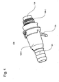
- Fig. 1 shows a perspective view of a filling head 100, for example, for refueling a liquid tank with an aqueous urea solution (SCR refueling).
- An aqueous urea solution is used in automobiles for after-treatment of exhaust gases in an SCR catalyst.
- Selective Catalytic Reduction (SCR) reduces nitrogen oxide emissions by about 90%.
- the aqueous urea solution is filled into the liquid tank with differently designed nozzles at a filling rate of up to 40 l / min. In this case, it should be prevented that the aqueous urea solution emerges from the filling head 100 and a so-called spit-back arises. In addition, a liquid outlet should be avoided even with repeated refueling with a nozzle as a filling nozzle. In addition, the SCR refueling should be possible with a screwed on the filling head Kruse bottle or an adapter for a canister.
- the filling head 100 is formed from a first filling head part 100-1 and a second filling head part 100-2.
- the first Be Schollkopfteil 100-1 and the second Be Schollkopfteil 100-2 are liquid and pressure-tight connected to each other and form a cavity inside, in which a dip tube molding is used.
- the dip tube molding forms inside the Be Schollkopfes 100 another part of a filler neck 104.
- the dip tube shaped body receives a nozzle as a filling nozzle and positions it in the filling 100. In addition, the dip tube shaped body limits the jet of liquid emerging from the filling.
- the filling head 100 comprises a large connecting piece 124 for connecting or plugging a filler pipe or hose, which leads into a liquid tank and a small connection piece 125 for connecting a ventilation line, which serves for air exchange or ventilation in a bottle refueling, if a bottle (Kruse bottle ) is screwed pressure-tight on a thread of the filling 100.
- Fig. 1 shows the filling head 100 from the outside without retaining plate and without the attached to the connecting pieces 124 and 125 hoses.
- the filling head 100 may be additionally equipped with a retaining plate for attachment to a body.
- the filling head parts 100-1 and 100-2 and the inner parts of the filling head 100 may be made, for example, of thermoplastic elastomers (TPE) or elastomer alloys, in particular of thermoplastic polyolefins such as TPE-O (uncrosslinked thermoplastic polymers), or block copolymers such as polyesters (TPE-E).
- TPE-E thermoplastic polyolefins
- TPE-E block copolymers
- Polyamide elastomers TPE-A
- Particularly advantageous is the preparation of polyoxymethylene (POM) or polyamides and their derivatives, as this can be a particular resistance of the filling realized. It is advantageous to the individual parts of the filling 100 in a technically simple manner by injection molding manufacture. All parts of the filling head 100 may comprise a material which prevents crystal formation of urea crystals on the surface thereof.
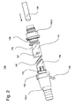
- Fig. 2 shows an exploded view of the filling head 100 and its individual parts.
- the filling head 100 comprises a dip tube shaped body 103 having a first molded part 117 and a second molded part 119. Between the first molded part 117 and the second molded part 119, a sealing element 107 is arranged, which seals the joint between the first molded part 117 and the second molded part 119.
- the first mold part 117, the second mold part 119 and the sealing element 107 form the dip tube shaped body 103.
- the first molded part 117 forms part of a filler neck 104 in the interior of the filling head 100.
- the second molded part 119 forms a part projecting beyond the filling nozzle 105 used for shaping and centering a liquid jet emanating from the filling nozzle 105 during refueling.
- the second molded part 117 By shaping the liquid jet by means of the second molded part 117, refueling at a high flow rate is ensured and accumulation of the liquid in the interior of the filling head 100 is prevented. It is particularly advantageous if the second molded part 119 is cylindrical or tubular with parallel walls, as this can produce a laminar flow of liquid.
- the first molded part 117 also serves to fix a ring magnet 129 in the interior of the filling head 100.
- the ring magnet 129 is inserted between the first shaped part 117 and the first filling head part 100-1 in a cavity.
- the ring magnet 129 generates a permanent magnetic field which can be detected by a filling nozzle 105 in order to determine the correct position of the filling nozzle 105 in the interior of the filling head 100.
- the first molded part 117 comprises two lateral latching openings 127 for engaging a latching hook 123.
- the second mold part 119 comprises two latching hooks 123 for engaging in the latching openings 127 of the first mold part 117.
- the first mold part 117 and the second mold part 119 engage the latching hooks 123 in the latching opening 127 and there is a firm connection, in a simple manner can be produced.
- other locking means may be provided as long as a mechanical connection of the first molded part 117 and the second molded part 119 is effected.
- a circular baffle 131 is arranged, which inhibits the flow of liquid into a liquid reservoir between the dip tube mold body 103 and a housing wall of the filling head 100.
- the back-flowing liquid is decelerated by the baffle 131 and it is prevented that the filling head 100 is completely flooded. Nevertheless, when refilling the liquid reservoir should be filled with a sufficient amount of liquid residue.
- the sealing element 107 protrudes into the inside of the dip tube shaped body 103 and seals the filling nozzle 105 with respect to the immersion tube shaped body 105 by the sealing element 107 laying circumferentially around the filling nozzle 105 laterally. This prevents liquid from being able to splash back between the filling nozzle 105 and the immersion tube shaped body 103.
- the sealing element 107 runs diagonally around the filling nozzle 105 in the longitudinal axis of the filling head 100.
- the technical advantage can be achieved that the sealing effect of the Be Schollkopfes 100 is increased, the filling nozzle 105 is sealed as far as possible inside the Be Schollkopfes 100 and an opening for a dispensing valve at the bottom of the filling nozzle 105 remains uncovered.
- the dispensing valve automatic ensures that the refilling process is automatically ended when the liquid tank is full.
- Fig. 3 1 shows a cross-sectional view of the filling head 100.
- the filling head 100 comprises the liquid reservoir 141 between the housing wall 143 and the dip tube shaped body 103.
- the liquid reservoir 141 forms a cylindrical cavity in which an amount of liquid sloshing out of the tank or a quantity of liquid flowing out of the filling nozzle 105 during refueling is taken up can be. As a result, leakage of the liquid from the filling head 100 is avoided.
- the baffle 131 is disposed at the lower end of the dip tube molding 103 at the entrance of the liquid reservoir 141. Liquid flowing into or out of the liquid reservoir 141 passes the baffle 131. Thereby, a flow into the liquid reservoir 141 can be inhibited, so that leakage of liquid from the filling head 100 is prevented. Passage openings 145, which determine the flow into the liquid reservoir 141, are formed in the baffle 131 for this purpose. The size, number and location of the passages 145 is matched to the size of this flow.
- the liquid reservoir 141 has a volume of 160 ml to 200 ml, since in this case, leakage of liquid from the filling head 100 can be avoided even with a three refueling with a dispensing valve automatic.
- Fig. 4 shows a perspective view of a dip tube shaped body 103.
- an opening 133 can escape from the air from the liquid reservoir 141, so that the formation of an air cushion in the liquid reservoir 141 is prevented.
- a pressure pad could prevent the fluid reservoir 141 from being flooded, for example during a refueling event, so that fluid could escape from the fill head 100.
- the size and the position of the opening 133 are matched to the function of the filling head 100 and the liquid reservoir 141.
- Fig. 5 shows a cross-sectional view of the dip tube shaped body 103 with separate molded body parts 117 and 119.
- the first molded part 117 has a diagonal about the longitudinal axis of the filling head circumferential support surface 135 for the sealing member 107.
- the sealing element 107 abuts.
- the second molded part 119 comprises a further bearing surface 139 against which an opposite side of the sealing element 107 rests.
- the sealing member 107 is clamped during assembly of the dip tube shaped body 103 between the bearing surfaces 135 and 139 and held by them.
- the advantage is achieved that improves the sealing effect of the sealing element 107 within the dip tube shaped body 103.
- the stopper portion 137 is formed on the inside of the second die 119, so that the filling nozzle 105 abuts the stopper portion 137 with its front end when inserted into the filler neck 104 ,
- the abutment portion 137 is formed, for example, by a wall portion protruding inside the second molded part 119, which extends along the filling direction. In this way, turbulence of the liquid can be prevented even at high filling speeds.
- the first molded part 117 comprises a circumferential wall 147, which comprises a cylindrical receiving space for receiving the second molded part 119.
- Fig. 6 shows a cross-sectional view of the dip tube shaped body 103 with composite molded body parts 117 and 119 and the sealing member 107.
- the first mold part 117 is configured such that a wall 147, the second mold part 119 engages laterally.
- the second mold part 119 is received in the first mold part 117. This increases the sealing effect between the two mold parts 117 and 119 in addition.
- the latching hooks 123 are hooked into the latching openings 127.
- the second molded part 119 has in the bearing surface a circumferential recess 137 for the positive insertion of a projecting portion of the sealing element 107 in the dip tube shaped body 103.
- a circumferential recess 137 for the positive insertion of a projecting portion of the sealing element 107 in the dip tube shaped body 103.
- a positioning spring may be provided in the second mold part 119, which engages in a positioning groove in the sealing element, by means of which the correct seating of the sealing element 107 during assembly of the molded body is ensured.
- Fig. 7 shows a further cross-sectional view of the dip tube shaped body 103 with composite molded body parts 117 and 119, in which a dashed line indicates the position of the filling nozzle 105 used.
- the locations 107-1 and 107-2 are the locations in the cross-sectional plane at which the filling nozzle 105 bears against the sealing element 107.
- the sealing line around the filling nozzle 105 runs diagonally around the sealing line to prevent the liquid from being splashed back.
- Fig. 8 shows several views of a sealing element 107.
- the sealing element 107 is located in the filler neck 104, which is formed by the dip tube molding 103 and the first Be Schollkopfteil 100-1. In the longitudinal direction of the filler neck 104, the sealing member 107 runs diagonally around to seal the filler neck 104 with respect to the filling nozzle 105.
- the sealing member 107 may include a material that prevents crystal formation of urea crystals on the surface thereof.
- the sealing element 107 is formed by an elastic annular disc 109 with an oval insertion opening 111 for insertion of the filling nozzle 105.
- the oval insertion opening 111 lies in a diagonal arrangement of the sealing element 107 to the circular cross-section outside of the filling nozzle 105th
- the diagonal position of the sealing element 107 ensures that the differently arranged openings in nozzles for the dispensing valve automatic will not be obscured and a shutdown of the respective nozzle remains possible.
- the annular disc 109 comprises a reinforcing portion 113 for reinforcing the sealing member 107 in the region of the insertion opening 111.
- the reinforcing portion 113 may be formed, for example, by an area having a thickness greater than the thickness of the remaining annular disc 109, for example by a circumferential annular bead 115 Sealing edge of the sealing element 107 is thereby not only reinforced, but also rounded, so that insertion of the filling nozzle 105 is facilitated.
- the immersion tube shaped body 103 has a recess for inserting the sealing element 107.
- the recess for inserting the sealing element 107 between a first molded part 117 and a second molded part between two bearing surfaces 135 and 139 is formed.
- Both the first mold part 117 and the second mold part 119 may include the recess for inserting the sealing element 107.
- the sealing element 107 has a circumferential raised or protruding edge portion 115, which is inserted into a corresponding annular recess in the filler neck 104 and additionally fixes the sealing element 107 in the filler neck 104.
- the sealing element 107 comprises a positioning groove 116 for engaging in a corresponding positioning spring, by means of which the correct seating of the sealing element 107 can be ensured.
- the sealing member 107 may be formed of any suitable sealing materials, for example, polyurethane, silicone, silane-modified polymers or rubber.
- nozzle nozzles and GL adapter for canisters and Kruse bottles can be added.
- the filling head 100 is formed by the liquid reservoir 141 such that remindschwappmenge (Spit-back amount) can be added.
- the filling head 100 allows a pressure reduction and unifies the liquid jet of different nozzles when filling. A spilling back of liquid (spit-back) is effectively prevented.
- crystal formation in the interior of the filling head 100 can be prevented.
- the filling head 100 allows filling speeds of 40 l / min with a small compact filling head, without any spilling back of liquid.
- the arrangement, position and shape of the sealing element is a three refills without liquid leakage possible.
- the filling process with the filling head 100 is initiated by a manual actuation of the fuel nozzle. Via the filling head 100, after the opening of a flap valve, the liquid enters the liquid tank and the liquid tank is filled with an aqueous urea solution. In the liquid tank, the liquid displaces air that soaks through a vent valve. Subsequently, the liquid level rises up to the dip tube shaped body 103 and the internal tank pressure and the liquid level rise. A float valve closes and the liquid reaches the filling nozzle of the fuel nozzle, which then turns off the automatic dispensing valve. A flap valve closes and the refueling process is finished.
Landscapes
- Engineering & Computer Science (AREA)
- Life Sciences & Earth Sciences (AREA)
- Sustainable Development (AREA)
- Sustainable Energy (AREA)
- Chemical & Material Sciences (AREA)
- Combustion & Propulsion (AREA)
- Transportation (AREA)
- Mechanical Engineering (AREA)
- Cooling, Air Intake And Gas Exhaust, And Fuel Tank Arrangements In Propulsion Units (AREA)
- Ink Jet (AREA)
Description
- Die vorliegende Erfindung betrifft einen Befüllkopf für einen Flüssigkeitstank in einem Kraftfahrzeug.
- Die Druckschrift
WO 90/014244 - Die Druckschrift
US 2011/284128 A1 betrifft ein Einwegeventil für einen Kraftstofftankfüllstutzen. Der Kraftstofftankfüllstutzen umfasst drehbar gelagerte Blockierelemente, die diagonal in dem Kraftstofftankfüllstutzen angeordnet sind. - Die gattungsbildende Druckschrift
US 2007/210607 A1 betrifft eine Füllkopfanordnung für Kraftfahrzeuge. - Bei dieser senkrechten Anordnung entstehen beim Einführen der Befülldüse in den Einfüllstutzen ein hoher Widerstand und eine hohe Belastung für die Kombinationsdichtung. Dadurch kann die Kombinationsdichtung beschädigt werden. Daneben ist die Kombinationsdichtung im oberen Teil des Einfüllstutzens angeordnet. Kommt es zu einem Rückschwappen (Spit-Back) besteht die Gefahr, dass Flüssigkeit aus dem Einfüllstutzen austritt. Wird hingegen eine senkrecht zur Befüllrichtung stehende Dichtung weiter Innen im Einfüllstutzen am unteren Ende einer Befülldüse angeordnet, so kann möglicherweise eine Öffnung in der Befülldüse verschlossen werden, die zum Auslösen eines Rückschlagventils dient.
- Es ist die der Erfindung zugrundeliegende Aufgabe, einen Befüllkopf mit verbesserter Dichtung anzugeben.
- Diese Aufgabe wird durch einen Gegenstand mit den Merkmalen nach dem unabhängigen Anspruch gelöst. Vorteilhafte Ausführungsformen der Erfindung sind Gegenstand der Figuren, der Beschreibung und der abhängigen Ansprüche.
- Gemäß einem Aspekt der Erfindung wird die Aufgabe durch einen Befüllkopf für einen Flüssigkeitstank in einem Kraftfahrzeug gelöst, mit einem Einfüllstutzen zum Einführen einer Befülldüse und einem diagonal um eine Längsachse des Einfüllstutzens umlaufenden Dichtungselement zum Abdichten des Einfüllstutzens, das durch eine elastische Ringscheibe mit einer Einführöffnung zum Einführen der Befülldüse gebildet wird. Der Flüssigkeitstank kann ein Tank für eine wässrige Harnstofflösung sein (SCR-Tank).
- Dadurch wird beispielsweise der technische Vorteil erreicht, dass ein Einführen der Befülldüse erleichtert wird und auf das Dichtungselement ausgeübte Kräfte verringert werden. Die Dichtung kann im Einfüllstutzen tieferliegend angeordnet werden, ohne dass eine Öffnung zum Auslösen eines Rückschlagventils am unteren Ende der Befülldüse verdeckt wird. Dadurch wird beispielsweise der technische Vorteil erreicht, dass sich das Dichtungselement vollumfänglich an die Befülldüse anlegt und die Dichtwirkung verbessert wird.
- In einer weiteren vorteilhaften Ausführungsform weist die Einführöffnung eine ovale Form auf. Dadurch wird beispielsweise der technische Vorteil erreicht, dass sich das diagonal angeordnete Dichtungselement gleichmäßig um eine im Querschnitt kreisförmige Befülldüse legt.
- In einer weiteren vorteilhaften Ausführungsform weist die Ringscheibe einen Verstärkungsabschnitt zum Verstärken des Dichtungselementes um die Einführöffnung herum auf. Dadurch wird beispielsweise der technische Vorteil erreicht, dass eine Beschädigung des Dichtungselements durch die Befülldüse verhindert wird.
- In einer weiteren vorteilhaften Ausführungsform ist der Verstärkungsabschnitt durch einen Ringscheibenbereich mit einer größeren Dicke gebildet. Dadurch wird beispielsweise der technische Vorteil erreicht, dass sich der Verstärkungsabschnitt auf besonders einfache Weise realisieren lässt.
- In einer weiteren vorteilhaften Ausführungsform ist der Verstärkungsabschnitt durch eine ringförmige Wulst gebildet. Dadurch wird beispielsweise der technische Vorteil erreicht, dass sich der Verstärkungsabschnitt zusätzlich die Dichtwirkung des Dichtungselementes verbessert.
- In einer weiteren vorteilhaften Ausführungsform ist ein innerer Dichtungsrand des Dichtungselementes abgerundet. Dadurch wird beispielsweise der technische Vorteil erreicht, dass ein Einführen einer Befülldüse und ein Gleiten des Dichtungselementes auf der Befülldüse verbessert werden.
- In einer weiteren vorteilhaften Ausführungsform umfasst das Dichtungselement einen umlaufenden erhöhten Randabschnitt zum Fixieren des Dichtungselementes in einer umlaufenden Aussparung, die in dem Einfüllstutzen umläuft. Dadurch wird beispielsweise der technische Vorteil erreicht, dass eine Befestigung des Dichtungselementes verbessert wird.
- In einer weiteren vorteilhaften Ausführungsform umfasst das Dichtungselement einen Positionierungsabschnitt zum Positionieren des Dichtungselementes in dem Einfüllstutzen. Dadurch wird beispielsweise der technische Vorteil erreicht, dass beim Einsetzen des Dichtungselements eine korrekte Position anhand des Positionierungsabschnittes sichergestellt werden kann.
- In einer weiteren vorteilhaften Ausführungsform umfasst der Einfüllstutzen eine Aussparung zum Einsetzen des Dichtungselementes. Dadurch wird beispielsweise ebenfalls der technische Vorteil erreicht, dass eine Befestigung des Dichtungselementes verbessert wird.
- In einer weiteren vorteilhaften Ausführungsform umfasst der Einfüllstutzen ein erstes Formteil und ein zweites Formteil, zwischen denen das Dichtungselement eingesetzt ist. Dadurch wird beispielsweise der technische Vorteil erreicht, dass sich das Dichtungselement auf einfache Weise in den Einfüllstutzen einsetzen lässt.
- In einer weiteren vorteilhaften Ausführungsform umfasst das erste Formteil ein Rastmittel zum Einrasten in dem zweiten Formteil oder das zweite Formteil ein Rastmittel zum Einrasten in dem ersten Formteil, um das Dichtungselement zwischen dem ersten Formteil und dem zweiten Formteil einzuklemmen. Dadurch wird beispielsweise der technische Vorteil erreicht, dass eine schnelle Montage des Dichtungselementes durchgeführt werden kann.
- In einer weiteren vorteilhaften Ausführungsform umfasst das erste Formteil oder das zweite Formteil eine diagonal umlaufende Auflagefläche für das Dichtungselement. Dadurch wird beispielsweise der technische Vorteil erreicht, dass sich die Dichtwirkung des Dichtungselementes verbessert.
- In einer weiteren vorteilhaften Ausführungsform ist der Einfüllstutzen ein Kunststoffformteil. Dadurch wird beispielsweise der technische Vorteil erreicht, dass sich der Einfüllstutzen auf einfache Weise herstellen lässt.
- In einer weiteren vorteilhaften Ausführungsform ist das Dichtungselement aus Silikon oder Gummi gebildet. Dadurch wird beispielsweise der technische Vorteil erreicht, dass besonders geeignete Materialien für das Dichtungselement verwendet werden.
- Ausführungsbeispiele der Erfindung sind in den Zeichnungen dargestellt und werden im Folgenden näher beschrieben.
- Es zeigen:
- Fig. 1
- eine perspektivische Ansicht eines Befüllkopfes;
- Fig. 2
- eine Explosionsdarstellung des Befüllkopfes;
- Fig. 3
- eine Querschnittsansicht des Befüllkopfes;
- Fig. 4
- eine perspektivische Ansicht eines Tauchrohrformkörpers:
- Fig. 5
- eine Querschnittsansicht des Tauchrohrformkörpers mit getrennten Formkörperteilen;
- Fig. 6
- eine Querschnittsansicht des Tauchrohrformkörpers mit zusammengesetzten Formkörperteilen;
- Fig. 7
- eine weitere Querschnittsansicht des Tauchrohrformkörpers mit zusammengesetzten Formkörperteilen; und
- Fig. 8
- mehrere Ansichten eines Dichtungselementes.
-
Fig. 1 zeigt eine perspektivische Ansicht eines Befüllkopfes 100, beispielsweise zur Betankung eines Flüssigkeitstanks mit einer wässrigen Harnstofflösung (SCR-Betankung). Eine wässrige Harnstofflösung wird in Kraftfahrzeugen zur Nachbehandlung von Abgasen in einem SCR-Katalysator benutzt wird. Dabei wird durch selektive katalytische Reduktion (Selective Catalytic Reduction - SCR) der Ausstoß von Stickoxiden um etwa 90 % reduziert. - Bei der SCR-Betankung wird die wässrige Harnstofflösung mit unterschiedlich ausgebildeten Zapfpistolen mit einer Füllgeschwindigkeit von bis zu 40l/min in den Flüssigkeitstank gefüllt. Dabei sollte verhindert werden, dass die wässrige Harnstofflösung aus dem Befüllkopf 100 austritt und ein sogenannter Spit-Back entsteht. Daneben sollte auch bei mehrmaligem Nachtanken mit einer Zapfpistole als Befülldüse ein Flüssigkeitsaustritt vermieden werden. Zusätzlich sollte die SCR-Betankung mit einer auf den Befüllkopf aufgeschraubten Kruse-Flasche oder einem Adapter für einen Kanister möglich sein.
- Der Befüllkopf 100 ist aus einem ersten Befüllkopfteil 100-1 und einem zweiten Befüllkopfteil 100-2 gebildet. Das erste Befüllkopfteil 100-1 und das zweite Befüllkopfteil 100-2 sind flüssigkeits- und druckdicht miteinander verbunden und bilden im Inneren einen Hohlraum, in dem ein Tauchrohrformkörper eingesetzt ist. Der Tauchrohrformkörper bildet im Inneren des Befüllkopfes 100 einen weiteren Teil eines Einfüllstutzens 104. Der Tauchrohrformkörper nimmt eine Zapfpistole als Befülldüse auf und positioniert diese in dem Befüllkopf 100. Zusätzlich begrenzt der Tauchrohrformkörper den Strahl der aus der Befülldüse austretenden Flüssigkeit.
- Daneben umfasst der Befüllkopf 100 einen großen Anschlussstutzen 124 zum Anschließen oder Aufstecken eines Einfüllrohres oder Schlauches, der in einen Flüssigkeitstank führt und einen kleinen Anschlussstutzen 125 zum Anschließen einer Belüftungsleitung, die zum Luftaustausch oder Belüftung bei einer Flaschenbetankung dient, falls eine Flasche (Kruse-Flasche) druckdicht auf einem Gewinde des Befüllkopfes 100 verschraubt wird.
Fig. 1 zeigt den Befüllkopf 100 von außen ohne Halteblech und ohne die an den Anschlussstutzen 124 und 125 aufgesteckten Schläuche. Der Befüllkopf 100 kann zur Befestigung an einer Karosserie zusätzlich mit einem Halteblech ausgerüstet sein. - Die Befüllkopfteile 100-1 und 100-2 und die Innenteile des Befüllkopfes 100 können beispielsweise aus thermoplastischen Elastomeren (TPE) oder Elastomerlegierungen, insbesondere aus thermoplastischen Polyolefinen wie TPE-O (unvernetzte thermoplastische Polymere), oder Blockcopolymeren wie beispielsweise Polyestern (TPE-E), Polyamidelastomeren (TPE-A) gebildet sein. Besonders vorteilhaft ist die Herstellung aus Polyoxymethylen (POM) oder Polyamiden und deren Derivate, da sich hierdurch eine besondere Widerstandsfähigkeit des Befüllkopfes realisieren lässt. Vorteilhaft ist es, die Einzelteile des Befüllkopfes 100 auf technisch einfache Weise im Spritzgussverfahren herzustellen. Alle Teile des Befüllkopfes 100 können ein Material umfassen, das eine Kristallbildung von Harnstoffkristallen an deren Oberfläche verhindert.
-
Fig. 2 zeigt eine Explosionsdarstellung des Befüllkopfes 100 und seiner Einzelteile. Der Befüllkopf 100 umfasst einen Tauchrohrformkörper 103 mit einem ersten Formteil 117 und einem zweiten Formteil 119. Zwischen dem ersten Formteil 117 und dem zweiten Formteil 119 ist ein Dichtungselement 107 angeordnet, das die Verbindungsstelle zwischen dem ersten Formteil 117 und dem zweiten Formteil 119 abdichtet. Das erste Formteil 117, das zweite Formteil 119 und das Dichtungselement 107 bilden den Tauchrohrformkörper 103. - Das erste Formteil 117 bildet einen Teil eines Einfüllstutzens 104 im Inneren des Befüllkopfes 100. Das zweite Formteil 119 bildet einen über die eingesetzte Befülldüse 105 hinausragenden Teil zum Formen und Zentrieren eines von der Befülldüse 105 beim Betanken ausgehenden Flüssigkeitsstrahles.
- Durch das Formen des Flüssigkeitsstrahles mittels des zweiten Formteils 117 wird eine Betankung mit einer hohen Durchflussgeschwindigkeit sichergestellt und ein Ansammeln der Flüssigkeit im Inneren des Befüllkopfes 100 verhindert. Besonders vorteilhaft ist es, wenn das zweite Formteil 119 zylinder- oder rohrförmig mit parallelen Wänden ist, da hierdurch eine laminare Flüssigkeitsströmung erzeugt werden kann.
- Das erste Formteil 117 dient daneben zum Fixieren eines Ringmagneten 129 im Inneren des Befüllkopfes 100. Der Ringmagnet 129 ist zwischen dem ersten Formteil 117 und dem ersten Befüllkopfteil 100-1 in einem Hohlraum eingesetzt. Der Ringmagnet 129 erzeugt ein dauerhaftes magnetisches Feld, das von einer Befülldüse 105 erfasst werden kann, um die korrekte Position der Befülldüse 105 im Inneren des Befüllkopfes 100 zu bestimmen. Weiter umfasst das erste Formteil 117 zwei seitliche Rastöffnungen 127 zum Eingreifen eines Rasthakens 123.
- Das zweite Formteil 119 umfasst zwei Rasthaken 123 zum Eingreifen in die Rastöffnungen 127 des ersten Formteils 117. Beim Zusammenstecken des ersten Formteils 117 und des zweiten Formteils 119 rasten die Rasthaken 123 in der Rastöffnung 127 ein und es entsteht eine feste Verbindung, die auf einfache Weise hergestellt werden kann. Im Allgemeinen können jedoch auch andere Rastmittel vorgesehen sein, solange durch die eine mechanische Verbindung des ersten Formteils 117 und des zweiten Formteils 119 bewirkt wird.
- An dem unteren Ende des zweiten Formteils 119 ist eine kreisförmige Schwallwand 131 angeordnet, die die Flüssigkeitsströmung in ein Flüssigkeitsreservoir zwischen dem Tauchrohrformkörper 103 und einer Gehäusewand des Befüllkopfes 100 hemmt. Die zurückströmende Flüssigkeit wird durch die Schwallwand 131 abgebremst und es wird verhindert, dass der Befüllkopf 100 vollständig beflutet wird. Nichtsdestotrotz sollte beim Nachtanken das Flüssigkeitsreservoir mit einer ausreichenden Flüssigkeitsrestmenge befüllt werden können.
- Das Dichtungselement 107 ragt in die Innenseite des Tauchrohrformkörpers 103 hinein und dichtet die Befülldüse 105 gegenüber dem Tauchrohrformkörper 105 ab, indem sich das Dichtungselement 107 seitlich umlaufend um die Befülldüse 105 legt. Dadurch wird verhindert, dass Flüssigkeit zwischen der Befülldüse 105 und dem Tauchrohrformkörper 103 zurückspritzen kann. Das Dichtungselement 107 läuft in der Längsachse des Befüllkopfes 100 diagonal um die Befülldüse 105 um. Durch diese Anordnung lässt sich der technische Vorteil erreichen, dass die Dichtwirkung des Befüllkopfes 100 erhöht wird, die Befülldüse 105 möglichst weit im Inneren des Befüllkopfes 100 abgedichtet wird und eine Öffnung für eine Zapfventilautomatik am unteren Ende der Befülldüse 105 unverdeckt bleibt. Die Zapfventilautomatik sorgt dafür, dass der Tankvorgang bei vollem Flüssigkeitstank automatisch beendet wird.
-
Fig. 3 zeigt eine Querschnittsansicht des Befüllkopfes 100. Der Befüllkopf 100 umfasst zwischen der Gehäusewand 143 und dem Tauchrohrformkörper 103 das Flüssigkeitsreservoir 141. Das Flüssigkeitsreservoir 141 bildet einen zylinderförmigen Hohlraum, in dem eine aus dem Tank zurückschwappende Flüssigkeitsmenge oder eine beim Nachtanken aus der Befülldüse 105 ausströmende Flüssigkeitsmenge aufgenommen werden kann. Dadurch wird ein Austreten der Flüssigkeit aus dem Befüllkopf 100 vermieden. - Die Schwallwand 131 ist am unteren Ende des Tauchrohrformkörpers 103 am Eingang des Flüssigkeitsreservoirs 141 angeordnet. Flüssigkeit, die in oder aus dem Flüssigkeitsreservoir 141 fließt, passiert die Schwallwand 131. Dadurch kann ein Fluss in das Flüssigkeitsreservoir 141 gehemmt werden, so dass ein Austritt von Flüssigkeit aus dem Befüllkopf 100 verhindert wird. In der Schwallwand 131 sind zu diesem Zweck Durchtrittsöffnungen 145 gebildet, die den Fluss in das Flüssigkeitsreservoir 141 bestimmen. Die Größe, Anzahl und Lage der Durchtrittsöffnungen 145 ist auf die Größe dieses Flusses abgestimmt.
- Vorteilhaft ist es, wenn das Flüssigkeitsreservoir 141 ein Volumen von 160 ml bis 200 ml aufweist, da in diesem Fall auch bei einem dreimaligen Nachtanken mit einer Zapfventilautomatik ein Austreten von Flüssigkeit aus dem Befüllkopf 100 vermieden werden kann.
-
Fig. 4 zeigt eine perspektivische Ansicht eines Tauchrohrformkörpers 103. Am oberen Ende des ersten Formteils 117 befindet sich eine Öffnung 133 aus der Luft aus dem Flüssigkeitsreservoir 141 austreten kann, so dass die Bildung eines Luftpolsters im Flüssigkeitsreservoir 141 verhindert wird. Ein Druckpolster könnte verhindern, dass das Flüssigkeitsreservoir 141 beflutet werden kann, beispielsweise bei einem Nachtankvorgang, so dass Flüssigkeit aus dem Befüllkopf 100 austreten könnte. Die Größe und die Lage der Öffnung 133 sind auf die Funktion des Befüllkopfes 100 und das Flüssigkeitsreservoir 141 abgestimmt. -
Fig. 5 zeigt eine Querschnittsansicht des Tauchrohrformkörpers 103 mit getrennten Formkörperteilen 117 und 119. Das erste Formteil 117 weist eine diagonal um die Längsachse des Befüllkopfes umlaufende Auflagefläche 135 für das Dichtungselement 107 auf. An der Auflagefläche 135 liegt das Dichtungselement 107 an. In entsprechender Weise umfasst das zweite Formteil 119 eine weitere Auflagefläche 139, an der eine entgegengesetzte Seite der Dichtungselements 107 anliegt. Das Dichtungselement 107 wird beim Zusammensetzen des Tauchrohrformkörpers 103 zwischen den Auflageflächen 135 und 139 eingeklemmt und von diesen gehalten. Dadurch wird der Vorteil erreicht, dass sich die Dichtwirkung des Dichtungselementes 107 innerhalb des Tauchrohrformkörpers 103 verbessert. - Daneben umfasst der Tauchrohrformkörper 103 einen Anschlagsabschnitt 137 zum Bilden eines Anschlags für die Befülldüse 105. Der Anschlagsabschnitt 137 ist auf der Innenseite des zweiten Formteils 119 gebildet, so dass die Befülldüse 105 beim Einführen in den Einfüllstutzen 104 mit ihrem vorderen Ende an den Anschlagsabschnitt 137 stößt. Der Anschlagsabschnitt 137 ist beispielsweise durch einen im Inneren des zweiten Formteils 119 hervorstehenden Wandabschnitt gebildet, der sich entlang der Befüllrichtung erstreckt. Auf diese Weise kann eine Verwirbelung der Flüssigkeit auch bei hohen Füllgeschwindigkeiten verhindert werden. Das erste Formteil 117 umfasst eine umlaufende Wandung 147, die einen zylindrischen Aufnahmeraum zur Aufnahme des zweiten Formteils 119 umfasst.
-
Fig. 6 zeigt eine Querschnittsansicht des Tauchrohrformkörpers 103 mit zusammengesetzten Formkörperteilen 117 und 119 und dem Dichtungselement 107. Das erste Formteil 117 ist derart ausgestaltet, dass eine Wandung 147 das zweite Formteil 119 seitlich umgreift. Das zweite Formteil 119 ist in dem ersten Formteil 117 aufgenommen. Dadurch erhöht sich die Dichtwirkung zwischen den beiden Formteilen 117 und 119 zusätzlich. Die Rasthaken 123 sind in den Rastöffnungen 127 eingehakt. - Das zweite Formteil 119 weist in der Auflagefläche eine umlaufende Aussparung 137 zum formschlüssigen Einsetzen eines vorspringenden Abschnittes des Dichtungselementes 107 in dem Tauchrohrformkörper 103 auf. Dadurch wird nicht nur die Dichtwirkung des Dichtungselementes 107 erhöht, sondern es kann auch eine korrekte Lage des Dichtungselementes 107 beim Zusammensetzen des Tauchrohrformkörpers 103 sichergestellt werden. Daneben wird eine Halterung des Dichtungselementes 107 zwischen dem ersten Formteil 117 und dem zweiten Formteil 119 verbessert.
- Zusätzlich kann in dem zweiten Formteil 119 eine Positionierungsfeder vorgesehen sein, die in eine Positionierungsnut in dem Dichtungselement eingreift, anhand der der korrekte Sitz des Dichtungselementes 107 beim Zusammensetzen des Formkörpers sichergestellt wird.
-
Fig. 7 zeigt eine weitere Querschnittsansicht des Tauchrohrformkörpers 103 mit zusammengesetzten Formkörperteilen 117 und 119, in der eine gestrichelte Linie die Position der eingesetzten Befülldüse 105 angibt. Die Stellen 107-1 und 107-2 sind die Stellen in der Querschnittsebene, an denen die Befülldüse 105 an dem Dichtungselement 107 anliegt. Durch die um die Befülldüse 105 diagonal umlaufende Dichtlinie wird ein Zurückspritzen der Flüssigkeit verhindert. -
Fig. 8 zeigt mehrere Ansichten eines Dichtungselementes 107. Das Dichtungselement 107 befindet sich in dem Einfüllstutzen 104, der durch den Tauchrohrformkörper 103 und das erste Befüllkopfteil 100-1 gebildet wird. In der Längsrichtung des Einfüllstutzens 104 läuft das Dichtungselement 107 diagonal herum, um den Einfüllstutzen 104 gegenüber der Befülldüse 105 abzudichten. Das Dichtungselement 107 kann ein Material umfassen, das eine Kristallbildung von Harnstoffkristallen an dessen Oberfläche verhindert. - Das Dichtungselement 107 wird durch eine elastische Ringscheibe 109 mit einer ovalen Einführöffnung 111 zum Einführen der Befülldüse 105 gebildet. Die ovale Einführöffnung 111 legt sich bei einer diagonalen Anordnung des Dichtungselementes 107 an die im Querschnitt kreisförmige Außenseite der Befülldüse 105.
- Die diagonale Lage des Dichtungselementes 107 stellt sicher, dass die unterschiedlich angeordneten Öffnungen in Zapfpistolen für die Zapfventilautomatik nicht verdeckt werden und eine Abschaltung der jeweiligen Zapfpistole möglich bleibt.
- Die Ringscheibe 109 umfasst einen Verstärkungsabschnitt 113 zum Verstärken des Dichtungselementes 107 im Bereich der Einführöffnung 111. Der Verstärkungsabschnitt 113 kann beispielsweise durch einen Bereich mit einer größeren Dicke als die Dicke der übrigen Ringscheibe 109 gebildet sein, beispielsweise durch eine umlaufende ringförmige Wulst 115. Der innere Dichtungsrand des Dichtungselementes 107 wird dadurch nicht nur verstärkt, sondern zusätzlich auch abgerundet, so dass ein Einsetzen der Befülldüse 105 erleichtert wird.
- Zum Aufnehmen des Dichtungselementes weist der Tauchrohrformkörper 103 eine Aussparung zum Einsetzen des Dichtungselementes 107 auf. Insbesondere ist die Aussparung zum Einsetzen des Dichtungselementes 107 zwischen einem ersten Formteil 117 und einem zweiten Formteil zwischen zwei Auflageflächen 135 und 139 gebildet. Sowohl das erste Formteil 117 als auch das zweite Formteil 119 können die Aussparung zum Einsetzen des Dichtungselementes 107 umfassen.
- Das Dichtungselement 107 weist einen umlaufenden erhöhten oder vorstehenden Randabschnitt 115 auf, der in eine entsprechende ringförmige Aussparung in dem Einfüllstutzen 104 eingesetzt wird und das Dichtungselement 107 in dem Einfüllstutzen 104 zusätzlich fixiert. Daneben umfasst das Dichtungselement 107 eine Positionierungsnut 116 zum Eingreifen in eine entsprechende Positionierungsfeder, anhand der der korrekte Sitz des Dichtungselementes 107 sichergestellt werden kann. Das Dichtungselement 107 kann aus allen geeigneten Dichtmaterialien gebildet sein, beispielsweise aus Polyurethan, Silikon, silanmodifizierten Polymeren oder Gummi.
- Durch den erfindungsgemäßen Befüllkopf 100 können unterschiedliche Zapfpistolen sowie GL-Adapter für Kanister und Kruse-Flaschen aufgenommen werden. Eine Schaltung einer Zapfventilautomatik, beispielsweise einer ZVA-Pistole, erfolgt über den Ringmagnet 129 des Befüllkopfes 100. Daneben erfolgt eine Belüftung bei einer Betankung mit einer Kruse-Flasche und einem Kanister über einen Anschlussstutzen 124 für eine Belüftungsleitung.
- Weiter ist durch das Flüssigkeitsreservoir 141 der Befüllkopf 100 derart ausgebildet, dass Rückschwappmenge (Spit-Back-Menge) aufgenommen werden kann. Der Befüllkopf 100 ermöglicht einen Druckabbau und vereinheitlicht den Flüssigkeitsstrahl unterschiedlicher Zapfpistolen beim Befülllen. Ein Zurückschwappen von Flüssigkeit (Spit-Back) wird wirksam verhindert. Bei Verwendung des Befüllkopfes 100 zum Befüllen mit einer wässrigen Harnstofflösung kann eine Kristallbildung im Inneren des Befüllkopfes 100 verhindert werden.
- Insbesondere ermöglicht der Befüllkopf 100 Füllgeschwindigkeiten von 40l/min mit einem kleinen kompakten Befüllkopf, ohne dass ein Zurückschwappen von Flüssigkeit auftritt. Durch die Anordnung, Lage und Form des Dichtungselementes ist ein dreimaliges Nachtanken ohne Austritt von Flüssigkeit möglich.
- Der Tankvorgang mit dem Befüllkopf 100 wird durch ein manuelles Betätigen der Zapfpistole eingeleitet. Über den Befüllkopf 100 gelangt die Flüssigkeit nach dem Öffnen eines Klappenventils in den Flüssigkeitstank und der Flüssigkeitstank wird mit einer wässrigen Harnstofflösung gefüllt. In dem Flüssigkeitstank verdrängt die Flüssigkeit Luft, die über ein Entlüftungsventil einweicht. Anschließend steigt der Flüssigkeitspegel steigt bis an den Tauchrohrformkörper 103 und der Tankinnendruck und der Flüssigkeitsstand steigen. Ein Schwimmerventil schließt und die Flüssigkeit gelangt bis an die Befülldüse der Zapfpistole, deren Zapfventilautomatik daraufhin abschaltet. Ein Klappenventil schließt und der Tankvorgang ist beendet.
- Alle in Verbindung mit einzelnen Ausführungsformen der Erfindung erläuterten und gezeigten Merkmale können in unterschiedlicher Kombination in dem erfindungsgemäßen Gegenstand vorgesehen sein, um gleichzeitig deren vorteilhafte Wirkungen zu realisieren.
- Der Schutzbereich der vorliegenden Erfindung ist durch die Ansprüche gegeben und wird durch die in der Beschreibung erläuterten oder den Figuren gezeigten Merkmale nicht beschränkt.
-
- 100
- Befüllkopf
- 100-1
- Befüllkopfteil
- 100-2
- Befüllkopfteil
- 103
- Tauchrohrformkörper
- 104
- Einfüllstutzen
- 105
- Befülldüse
- 107
- Dichtungselement
- 109
- Ringscheibe
- 111
- Einführöffnung
- 113
- Verstärkungsabschnitt
- 115
- Wulst
- 116
- Positionierungsnut
- 117
- erstes Formteil
- 119
- zweites Formteil
- 123
- Rasthaken
- 127
- Rastöffnung
- 131
- Schwallwand
- 133
- Öffnung
- 135
- Auflagefläche
- 137
- Anschlagsabschnitt
- 139
- Auflagefläche
- 141
- Flüssigkeitsreservoir
- 143
- Gehäusewand
- 145
- Durchtrittsöffnung
- 147
- Wandung
Claims (14)
- Befüllkopf (100) für einen Flüssigkeitstank in einem Kraftfahrzeug, mit:einem Einfüllstutzen (104) zum Einführen einer Befülldüse (105) mit einem Dichtungselement (107) zum Abdichten des Einfüllstutzens (104), das durch eine elastische Ringscheibe (109) mit einer Einführöffnung (111) zum Einführen der Befülldüse (105) gebildet wird, gekennzeichnet dadurch, dass das Dichtungselement (107) diagonal um eine Längsachse des Einfüllstutzens (104) umläuft.
- Befüllkopf (100) nach Anspruch 1, wobei die Einführöffnung (111) eine ovale Form aufweist.
- Befüllkopf (100) nach einem der vorangehenden Ansprüche, wobei die Ringscheibe (109) einen Verstärkungsabschnitt (113) zum Verstärken des Dichtungselementes (107) um die Einführöffnung (111) herum aufweist.
- Befüllkopf (100) nach Anspruch 3, wobei der Verstärkungsabschnitt (113) durch einen Ringscheibenbereich mit einer größeren Dicke gebildet wird.
- Befüllkopf (100) nach Anspruch 3 oder 4, wobei der Verstärkungsabschnitt (113) durch eine ringförmige Wulst (115) gebildet wird.
- Befüllkopf (100) nach einem der vorangehenden Ansprüche, wobei ein innerer Dichtungsrand des Dichtungselementes (107) abgerundet ist.
- Befüllkopf (100) nach einem der vorangehenden Ansprüche, wobei das Dichtungselement (107) einen umlaufenden erhöhten Randabschnitt (115) zum Fixieren des Dichtungselementes (107) in einer umlaufenden Aussparung umfasst, die in dem Einfüllstutzen (104) umläuft.
- Befüllkopf nach einem der vorangehenden Ansprüche, wobei das Dichtungselement (107) einen Positionierungsabschnitt (116) zum Positionieren des Dichtungselementes (107) in dem Einfüllstutzen (104) umfasst.
- Befüllkopf (100) nach einem der vorangehenden Ansprüche, wobei der Einfüllstutzen (104) eine Aussparung zum Einsetzen des Dichtungselementes (107) umfasst.
- Befüllkopf (100) nach einem der vorangehenden Ansprüche, wobei der Einfüllstutzen (104) ein erstes Formteil (117) und ein zweites Formteil (119) umfasst, zwischen denen das Dichtungselement (107) eingesetzt ist.
- Befüllkopf (100) nach Anspruch 10, wobei das erste Formteil (117) ein Rastmittel (123) zum Einrasten in dem zweiten Formteil (119) oder das zweite Formteil (119) ein Rastmittel zum Einrasten in dem ersten Formteil (117) umfasst, um das Dichtungselement (107) zwischen dem ersten Formteil (117) und dem zweiten Formteil (119) einzuklemmen.
- Befüllkopf (100) nach einem der Ansprüche 10 oder 11, wobei das erste Formteil (117) oder das zweite Formteil (119) eine diagonal umlaufende Auflagefläche (135, 139) für das Dichtungselement (107) umfasst.
- Befüllkopf (100) nach einem der vorangehenden Ansprüche, wobei der Einfüllstutzen (104) ein Kunststoffformteil ist.
- Befüllkopf (100) nach einem der vorangehenden Ansprüche, wobei das Dichtungselement aus Silikon oder Gummi gebildet ist.
Applications Claiming Priority (1)
| Application Number | Priority Date | Filing Date | Title |
|---|---|---|---|
| DE102012109562.0A DE102012109562A1 (de) | 2012-10-09 | 2012-10-09 | Befüllkopf für einen Flüssigkeitstank |
Publications (2)
| Publication Number | Publication Date |
|---|---|
| EP2719566A1 EP2719566A1 (de) | 2014-04-16 |
| EP2719566B1 true EP2719566B1 (de) | 2014-12-03 |
Family
ID=48793917
Family Applications (1)
| Application Number | Title | Priority Date | Filing Date |
|---|---|---|---|
| EP13176134.8A Active EP2719566B1 (de) | 2012-10-09 | 2013-07-11 | Befüllkopf für einen Flüssigkeitstank |
Country Status (3)
| Country | Link |
|---|---|
| EP (1) | EP2719566B1 (de) |
| DE (1) | DE102012109562A1 (de) |
| ES (1) | ES2530813T3 (de) |
Families Citing this family (5)
| Publication number | Priority date | Publication date | Assignee | Title |
|---|---|---|---|---|
| DE102016102737A1 (de) | 2015-09-22 | 2017-03-23 | Dr. Ing. H.C. F. Porsche Aktiengesellschaft | Einfüllstutzen |
| US10640358B2 (en) | 2017-06-21 | 2020-05-05 | Ford Global Technologies, Llc | Capless refill adapter for a fluid refilling system |
| DE102018118272A1 (de) * | 2018-07-27 | 2020-01-30 | Kautex Textron Gmbh & Co. Kg | Einfüllstutzen für druckloses Betankungsabschalten und Nachtanken und Betriebsflüssigkeitsbehälter mit Einfüllstutzen |
| DE102020123321A1 (de) | 2020-09-07 | 2022-03-10 | Röchling Automotive SE & Co. KG | Befüllköpfe |
| DE102020124193A1 (de) | 2020-09-16 | 2022-03-17 | Röchling Automotive SE & Co. KG | Befüllkopf |
Family Cites Families (4)
| Publication number | Priority date | Publication date | Assignee | Title |
|---|---|---|---|---|
| US4924923A (en) | 1989-05-17 | 1990-05-15 | Vernay Laboratories, Inc. | Fuel filler pipe seal |
| JP4769600B2 (ja) * | 2006-03-09 | 2011-09-07 | 本田技研工業株式会社 | 給油口装置 |
| DE202006006249U1 (de) * | 2006-04-10 | 2007-08-23 | Reutter Metallwarenfabrik Gmbh | Flüssigkeitsbehälter |
| US8439088B2 (en) * | 2010-05-19 | 2013-05-14 | Ford Global Technologies, Llc | One-way valve for a fuel-tank filling conduit |
-
2012
- 2012-10-09 DE DE102012109562.0A patent/DE102012109562A1/de not_active Withdrawn
-
2013
- 2013-07-11 ES ES13176134T patent/ES2530813T3/es active Active
- 2013-07-11 EP EP13176134.8A patent/EP2719566B1/de active Active
Also Published As
| Publication number | Publication date |
|---|---|
| EP2719566A1 (de) | 2014-04-16 |
| ES2530813T3 (es) | 2015-03-06 |
| DE102012109562A1 (de) | 2014-04-10 |
Similar Documents
| Publication | Publication Date | Title |
|---|---|---|
| EP2719567B1 (de) | Befüllkopf für einen Flüssigkeitstank | |
| EP2927040B1 (de) | Befüllkopf für einen flüssigkeitstank | |
| DE102013013213B4 (de) | Betriebsflüssigkeitsbehälter mit integriertem Ent- und/oder Belüftungsventil | |
| EP2752326B1 (de) | Befüllkopf | |
| DE602004000664T2 (de) | Rückschlagventil für Kraftstoffeinfüllstutzen | |
| EP2719566A1 (de) | Befüllkopf für einen Flüssigkeitstank | |
| DE102013103624A1 (de) | Befüllkopf für einen Flüssigkeitstank | |
| DE19733949C1 (de) | Kraftstoffversorgungssystem | |
| EP3149301A1 (de) | Vorratsbehälter für wässrige harnstofflösung in einem kfz | |
| DE102014010989B4 (de) | Einfüllstutzen für einen Flüssigkeitsbehälter, insbesondere für einen Harnstoffbehälter | |
| EP2738365B1 (de) | Leitungsventil für eine Flüssigkeitsleitung | |
| DE102017125329B4 (de) | Harnstoff-Füllvorrichtung für Diesel-Fahrzeuge | |
| WO2007118613A1 (de) | Flüssigkeitsbehälter | |
| EP3236033B1 (de) | Kombinationsventil zum befüllen und entlüften eines flüssigkeitstanks | |
| DE102018104037B4 (de) | System zum Verbessern der Entlüftung und Minderung der Leckage für einen Tank | |
| EP3418097B1 (de) | Befüllkopf für einen flüssigkeitstank | |
| DE202012012136U1 (de) | Abdeckung mit Einfüllstutzen | |
| WO2013034266A1 (de) | Einfüllstutzen für ein fahrzeug | |
| EP3418096B1 (de) | Befüllkopf für einen flüssigkeitstank | |
| DE102006056707B4 (de) | Reduktionsmittelbehälter und Reduktionsmittelanordnung zum Einfüllen und/oder Nachfüllen von Reduktionsmittel | |
| DE102011115401A1 (de) | Schlauchanbindungseinheit eines Kraftfahrzeugs, mit einem Stutzen | |
| DE102019120841A1 (de) | Einfüllstutzen zum einfüllen eines betriebs- oder zusatzstoffes in einen fahrzeugtank mittels einer zapfpistole | |
| DE102016106586A1 (de) | Entlüftungsventil mit einem elastischen Formkörper | |
| DE102016003122A1 (de) | Tanksystem zum Aufnehmen eines flüssigen Reduktionsmittels | |
| DE202013105733U1 (de) | Steckverbinder mit Auslaufschutz |
Legal Events
| Date | Code | Title | Description |
|---|---|---|---|
| PUAI | Public reference made under article 153(3) epc to a published international application that has entered the european phase |
Free format text: ORIGINAL CODE: 0009012 |
|
| AK | Designated contracting states |
Kind code of ref document: A1 Designated state(s): AL AT BE BG CH CY CZ DE DK EE ES FI FR GB GR HR HU IE IS IT LI LT LU LV MC MK MT NL NO PL PT RO RS SE SI SK SM TR |
|
| AX | Request for extension of the european patent |
Extension state: BA ME |
|
| 17P | Request for examination filed |
Effective date: 20140331 |
|
| RBV | Designated contracting states (corrected) |
Designated state(s): AL AT BE BG CH CY CZ DE DK EE ES FI FR GB GR HR HU IE IS IT LI LT LU LV MC MK MT NL NO PL PT RO RS SE SI SK SM TR |
|
| GRAP | Despatch of communication of intention to grant a patent |
Free format text: ORIGINAL CODE: EPIDOSNIGR1 |
|
| RIC1 | Information provided on ipc code assigned before grant |
Ipc: B60K 15/03 20060101ALN20140724BHEP Ipc: B60K 15/04 20060101ALI20140724BHEP Ipc: B60K 15/035 20060101AFI20140724BHEP Ipc: F01N 3/20 20060101ALI20140724BHEP |
|
| INTG | Intention to grant announced |
Effective date: 20140811 |
|
| GRAS | Grant fee paid |
Free format text: ORIGINAL CODE: EPIDOSNIGR3 |
|
| GRAA | (expected) grant |
Free format text: ORIGINAL CODE: 0009210 |
|
| AK | Designated contracting states |
Kind code of ref document: B1 Designated state(s): AL AT BE BG CH CY CZ DE DK EE ES FI FR GB GR HR HU IE IS IT LI LT LU LV MC MK MT NL NO PL PT RO RS SE SI SK SM TR |
|
| REG | Reference to a national code |
Ref country code: GB Ref legal event code: FG4D Free format text: NOT ENGLISH |
|
| REG | Reference to a national code |
Ref country code: AT Ref legal event code: REF Ref document number: 699155 Country of ref document: AT Kind code of ref document: T Effective date: 20141215 Ref country code: CH Ref legal event code: EP |
|
| REG | Reference to a national code |
Ref country code: IE Ref legal event code: FG4D Free format text: LANGUAGE OF EP DOCUMENT: GERMAN |
|
| REG | Reference to a national code |
Ref country code: DE Ref legal event code: R096 Ref document number: 502013000218 Country of ref document: DE Effective date: 20150115 |
|
| REG | Reference to a national code |
Ref country code: ES Ref legal event code: FG2A Ref document number: 2530813 Country of ref document: ES Kind code of ref document: T3 Effective date: 20150306 |
|
| REG | Reference to a national code |
Ref country code: NL Ref legal event code: VDEP Effective date: 20141203 |
|
| PG25 | Lapsed in a contracting state [announced via postgrant information from national office to epo] |
Ref country code: FI Free format text: LAPSE BECAUSE OF FAILURE TO SUBMIT A TRANSLATION OF THE DESCRIPTION OR TO PAY THE FEE WITHIN THE PRESCRIBED TIME-LIMIT Effective date: 20141203 Ref country code: NO Free format text: LAPSE BECAUSE OF FAILURE TO SUBMIT A TRANSLATION OF THE DESCRIPTION OR TO PAY THE FEE WITHIN THE PRESCRIBED TIME-LIMIT Effective date: 20150303 Ref country code: NL Free format text: LAPSE BECAUSE OF FAILURE TO SUBMIT A TRANSLATION OF THE DESCRIPTION OR TO PAY THE FEE WITHIN THE PRESCRIBED TIME-LIMIT Effective date: 20141203 Ref country code: LT Free format text: LAPSE BECAUSE OF FAILURE TO SUBMIT A TRANSLATION OF THE DESCRIPTION OR TO PAY THE FEE WITHIN THE PRESCRIBED TIME-LIMIT Effective date: 20141203 |
|
| REG | Reference to a national code |
Ref country code: LT Ref legal event code: MG4D |
|
| PG25 | Lapsed in a contracting state [announced via postgrant information from national office to epo] |
Ref country code: GR Free format text: LAPSE BECAUSE OF FAILURE TO SUBMIT A TRANSLATION OF THE DESCRIPTION OR TO PAY THE FEE WITHIN THE PRESCRIBED TIME-LIMIT Effective date: 20150304 Ref country code: LV Free format text: LAPSE BECAUSE OF FAILURE TO SUBMIT A TRANSLATION OF THE DESCRIPTION OR TO PAY THE FEE WITHIN THE PRESCRIBED TIME-LIMIT Effective date: 20141203 Ref country code: HR Free format text: LAPSE BECAUSE OF FAILURE TO SUBMIT A TRANSLATION OF THE DESCRIPTION OR TO PAY THE FEE WITHIN THE PRESCRIBED TIME-LIMIT Effective date: 20141203 Ref country code: SE Free format text: LAPSE BECAUSE OF FAILURE TO SUBMIT A TRANSLATION OF THE DESCRIPTION OR TO PAY THE FEE WITHIN THE PRESCRIBED TIME-LIMIT Effective date: 20141203 Ref country code: RS Free format text: LAPSE BECAUSE OF FAILURE TO SUBMIT A TRANSLATION OF THE DESCRIPTION OR TO PAY THE FEE WITHIN THE PRESCRIBED TIME-LIMIT Effective date: 20141203 Ref country code: CY Free format text: LAPSE BECAUSE OF FAILURE TO SUBMIT A TRANSLATION OF THE DESCRIPTION OR TO PAY THE FEE WITHIN THE PRESCRIBED TIME-LIMIT Effective date: 20141203 |
|
| PG25 | Lapsed in a contracting state [announced via postgrant information from national office to epo] |
Ref country code: CZ Free format text: LAPSE BECAUSE OF FAILURE TO SUBMIT A TRANSLATION OF THE DESCRIPTION OR TO PAY THE FEE WITHIN THE PRESCRIBED TIME-LIMIT Effective date: 20141203 Ref country code: EE Free format text: LAPSE BECAUSE OF FAILURE TO SUBMIT A TRANSLATION OF THE DESCRIPTION OR TO PAY THE FEE WITHIN THE PRESCRIBED TIME-LIMIT Effective date: 20141203 Ref country code: RO Free format text: LAPSE BECAUSE OF FAILURE TO SUBMIT A TRANSLATION OF THE DESCRIPTION OR TO PAY THE FEE WITHIN THE PRESCRIBED TIME-LIMIT Effective date: 20141203 Ref country code: SK Free format text: LAPSE BECAUSE OF FAILURE TO SUBMIT A TRANSLATION OF THE DESCRIPTION OR TO PAY THE FEE WITHIN THE PRESCRIBED TIME-LIMIT Effective date: 20141203 Ref country code: PT Free format text: LAPSE BECAUSE OF FAILURE TO SUBMIT A TRANSLATION OF THE DESCRIPTION OR TO PAY THE FEE WITHIN THE PRESCRIBED TIME-LIMIT Effective date: 20150403 |
|
| PG25 | Lapsed in a contracting state [announced via postgrant information from national office to epo] |
Ref country code: PL Free format text: LAPSE BECAUSE OF FAILURE TO SUBMIT A TRANSLATION OF THE DESCRIPTION OR TO PAY THE FEE WITHIN THE PRESCRIBED TIME-LIMIT Effective date: 20141203 Ref country code: IS Free format text: LAPSE BECAUSE OF FAILURE TO SUBMIT A TRANSLATION OF THE DESCRIPTION OR TO PAY THE FEE WITHIN THE PRESCRIBED TIME-LIMIT Effective date: 20150403 |
|
| REG | Reference to a national code |
Ref country code: DE Ref legal event code: R097 Ref document number: 502013000218 Country of ref document: DE |
|
| PLBE | No opposition filed within time limit |
Free format text: ORIGINAL CODE: 0009261 |
|
| STAA | Information on the status of an ep patent application or granted ep patent |
Free format text: STATUS: NO OPPOSITION FILED WITHIN TIME LIMIT |
|
| PG25 | Lapsed in a contracting state [announced via postgrant information from national office to epo] |
Ref country code: DK Free format text: LAPSE BECAUSE OF FAILURE TO SUBMIT A TRANSLATION OF THE DESCRIPTION OR TO PAY THE FEE WITHIN THE PRESCRIBED TIME-LIMIT Effective date: 20141203 |
|
| 26N | No opposition filed |
Effective date: 20150904 |
|
| PG25 | Lapsed in a contracting state [announced via postgrant information from national office to epo] |
Ref country code: MC Free format text: LAPSE BECAUSE OF FAILURE TO SUBMIT A TRANSLATION OF THE DESCRIPTION OR TO PAY THE FEE WITHIN THE PRESCRIBED TIME-LIMIT Effective date: 20141203 Ref country code: SI Free format text: LAPSE BECAUSE OF FAILURE TO SUBMIT A TRANSLATION OF THE DESCRIPTION OR TO PAY THE FEE WITHIN THE PRESCRIBED TIME-LIMIT Effective date: 20141203 |
|
| PG25 | Lapsed in a contracting state [announced via postgrant information from national office to epo] |
Ref country code: LU Free format text: LAPSE BECAUSE OF FAILURE TO SUBMIT A TRANSLATION OF THE DESCRIPTION OR TO PAY THE FEE WITHIN THE PRESCRIBED TIME-LIMIT Effective date: 20150711 |
|
| REG | Reference to a national code |
Ref country code: IE Ref legal event code: MM4A |
|
| REG | Reference to a national code |
Ref country code: FR Ref legal event code: PLFP Year of fee payment: 4 |
|
| PG25 | Lapsed in a contracting state [announced via postgrant information from national office to epo] |
Ref country code: IE Free format text: LAPSE BECAUSE OF NON-PAYMENT OF DUE FEES Effective date: 20150711 |
|
| REG | Reference to a national code |
Ref country code: DE Ref legal event code: R082 Ref document number: 502013000218 Country of ref document: DE Representative=s name: PATENTSHIP PATENTANWALTSGESELLSCHAFT MBH, DE |
|
| REG | Reference to a national code |
Ref country code: CH Ref legal event code: PL |
|
| PG25 | Lapsed in a contracting state [announced via postgrant information from national office to epo] |
Ref country code: MT Free format text: LAPSE BECAUSE OF FAILURE TO SUBMIT A TRANSLATION OF THE DESCRIPTION OR TO PAY THE FEE WITHIN THE PRESCRIBED TIME-LIMIT Effective date: 20141203 |
|
| PG25 | Lapsed in a contracting state [announced via postgrant information from national office to epo] |
Ref country code: LI Free format text: LAPSE BECAUSE OF NON-PAYMENT OF DUE FEES Effective date: 20160731 Ref country code: CH Free format text: LAPSE BECAUSE OF NON-PAYMENT OF DUE FEES Effective date: 20160731 |
|
| PG25 | Lapsed in a contracting state [announced via postgrant information from national office to epo] |
Ref country code: BG Free format text: LAPSE BECAUSE OF FAILURE TO SUBMIT A TRANSLATION OF THE DESCRIPTION OR TO PAY THE FEE WITHIN THE PRESCRIBED TIME-LIMIT Effective date: 20141203 Ref country code: HU Free format text: LAPSE BECAUSE OF FAILURE TO SUBMIT A TRANSLATION OF THE DESCRIPTION OR TO PAY THE FEE WITHIN THE PRESCRIBED TIME-LIMIT; INVALID AB INITIO Effective date: 20130711 |
|
| REG | Reference to a national code |
Ref country code: FR Ref legal event code: PLFP Year of fee payment: 5 |
|
| PG25 | Lapsed in a contracting state [announced via postgrant information from national office to epo] |
Ref country code: BE Free format text: LAPSE BECAUSE OF NON-PAYMENT OF DUE FEES Effective date: 20150731 |
|
| PG25 | Lapsed in a contracting state [announced via postgrant information from national office to epo] |
Ref country code: SM Free format text: LAPSE BECAUSE OF FAILURE TO SUBMIT A TRANSLATION OF THE DESCRIPTION OR TO PAY THE FEE WITHIN THE PRESCRIBED TIME-LIMIT Effective date: 20141203 |
|
| PG25 | Lapsed in a contracting state [announced via postgrant information from national office to epo] |
Ref country code: TR Free format text: LAPSE BECAUSE OF FAILURE TO SUBMIT A TRANSLATION OF THE DESCRIPTION OR TO PAY THE FEE WITHIN THE PRESCRIBED TIME-LIMIT Effective date: 20141203 Ref country code: MK Free format text: LAPSE BECAUSE OF FAILURE TO SUBMIT A TRANSLATION OF THE DESCRIPTION OR TO PAY THE FEE WITHIN THE PRESCRIBED TIME-LIMIT Effective date: 20141203 |
|
| REG | Reference to a national code |
Ref country code: FR Ref legal event code: PLFP Year of fee payment: 6 |
|
| PG25 | Lapsed in a contracting state [announced via postgrant information from national office to epo] |
Ref country code: AL Free format text: LAPSE BECAUSE OF FAILURE TO SUBMIT A TRANSLATION OF THE DESCRIPTION OR TO PAY THE FEE WITHIN THE PRESCRIBED TIME-LIMIT Effective date: 20141203 |
|
| REG | Reference to a national code |
Ref country code: AT Ref legal event code: MM01 Ref document number: 699155 Country of ref document: AT Kind code of ref document: T Effective date: 20180711 |
|
| PGFP | Annual fee paid to national office [announced via postgrant information from national office to epo] |
Ref country code: ES Payment date: 20190822 Year of fee payment: 7 |
|
| PG25 | Lapsed in a contracting state [announced via postgrant information from national office to epo] |
Ref country code: AT Free format text: LAPSE BECAUSE OF NON-PAYMENT OF DUE FEES Effective date: 20180711 |
|
| PGFP | Annual fee paid to national office [announced via postgrant information from national office to epo] |
Ref country code: GB Payment date: 20200724 Year of fee payment: 8 |
|
| REG | Reference to a national code |
Ref country code: ES Ref legal event code: FD2A Effective date: 20211228 |
|
| PG25 | Lapsed in a contracting state [announced via postgrant information from national office to epo] |
Ref country code: ES Free format text: LAPSE BECAUSE OF NON-PAYMENT OF DUE FEES Effective date: 20200712 |
|
| GBPC | Gb: european patent ceased through non-payment of renewal fee |
Effective date: 20210711 |
|
| PG25 | Lapsed in a contracting state [announced via postgrant information from national office to epo] |
Ref country code: GB Free format text: LAPSE BECAUSE OF NON-PAYMENT OF DUE FEES Effective date: 20210711 |
|
| REG | Reference to a national code |
Ref country code: DE Ref legal event code: R082 Ref document number: 502013000218 Country of ref document: DE Ref country code: DE Ref legal event code: R082 Ref document number: 502013000218 Country of ref document: DE Representative=s name: PATENTSHIP PATENTANWALTSGESELLSCHAFT MBH, DE |
|
| P01 | Opt-out of the competence of the unified patent court (upc) registered |
Effective date: 20230515 |
|
| REG | Reference to a national code |
Ref country code: DE Ref legal event code: R082 Ref document number: 502013000218 Country of ref document: DE Representative=s name: PATENTSHIP PATENTANWALTSGESELLSCHAFT MBH, DE Ref country code: DE Ref legal event code: R081 Ref document number: 502013000218 Country of ref document: DE Owner name: HDT VERITAS HESSEN GMBH, DE Free format text: FORMER OWNER: VERITAS AG, 63571 GELNHAUSEN, DE |
|
| PGFP | Annual fee paid to national office [announced via postgrant information from national office to epo] |
Ref country code: DE Payment date: 20250819 Year of fee payment: 13 |
|
| PGFP | Annual fee paid to national office [announced via postgrant information from national office to epo] |
Ref country code: IT Payment date: 20250729 Year of fee payment: 13 |
|
| PGFP | Annual fee paid to national office [announced via postgrant information from national office to epo] |
Ref country code: FR Payment date: 20250729 Year of fee payment: 13 |