EP2716933A1 - Drive belt and assembly method for drive belt - Google Patents
Drive belt and assembly method for drive belt Download PDFInfo
- Publication number
- EP2716933A1 EP2716933A1 EP11842459.7A EP11842459A EP2716933A1 EP 2716933 A1 EP2716933 A1 EP 2716933A1 EP 11842459 A EP11842459 A EP 11842459A EP 2716933 A1 EP2716933 A1 EP 2716933A1
- Authority
- EP
- European Patent Office
- Prior art keywords
- insertion groove
- inserting member
- face
- elements
- endplay
- Prior art date
- Legal status (The legal status is an assumption and is not a legal conclusion. Google has not performed a legal analysis and makes no representation as to the accuracy of the status listed.)
- Granted
Links
Images






Classifications
-
- F—MECHANICAL ENGINEERING; LIGHTING; HEATING; WEAPONS; BLASTING
- F16—ENGINEERING ELEMENTS AND UNITS; GENERAL MEASURES FOR PRODUCING AND MAINTAINING EFFECTIVE FUNCTIONING OF MACHINES OR INSTALLATIONS; THERMAL INSULATION IN GENERAL
- F16G—BELTS, CABLES, OR ROPES, PREDOMINANTLY USED FOR DRIVING PURPOSES; CHAINS; FITTINGS PREDOMINANTLY USED THEREFOR
- F16G5/00—V-belts, i.e. belts of tapered cross-section
- F16G5/16—V-belts, i.e. belts of tapered cross-section consisting of several parts
-
- Y—GENERAL TAGGING OF NEW TECHNOLOGICAL DEVELOPMENTS; GENERAL TAGGING OF CROSS-SECTIONAL TECHNOLOGIES SPANNING OVER SEVERAL SECTIONS OF THE IPC; TECHNICAL SUBJECTS COVERED BY FORMER USPC CROSS-REFERENCE ART COLLECTIONS [XRACs] AND DIGESTS
- Y10—TECHNICAL SUBJECTS COVERED BY FORMER USPC
- Y10T—TECHNICAL SUBJECTS COVERED BY FORMER US CLASSIFICATION
- Y10T29/00—Metal working
- Y10T29/49—Method of mechanical manufacture
- Y10T29/49826—Assembling or joining
- Y10T29/49895—Associating parts by use of aligning means [e.g., use of a drift pin or a "fixture"]
Definitions
- This invention relates to a driving belt formed by fastening a plurality of plate-like elements juxtaposed in a same orientation annularly by a flat ring, and to an assembling method thereof.
- a push type driving belt to be used in a belt type continuously variable transmission is known in the prior art.
- the driving belt of this kind is formed by annularly juxtaposing a plurality of plate members called an "element” or a “block” in a same orientation, and by fastening the juxtaposing plate members by an annular member such as a band, a hoop and a ring.
- an element comprises a first hole and a first projection formed at a head part, and a second hole and a second projection formed in an inner circumferential side of a rocking edge.
- a plurality of the elements thus formed are fastened by a ring in a circular manner to form the transmission belt.
- the transmission belt taught by Japanese Patent Laid-Open No. 2006-266363 therefore, the first projection is inserted into the first hole but the second hole and projection are disengaged from each other in a straight region of the transmission belt between pulleys. Meanwhile, in a curved region of the transmission belt around the pulley, the first hole and the first projection are disengaged from each other but the second projection is inserted into the second hole.
- the conventional driving belt is assembled by fastening the array of the element having the projection using the ring.
- a sufficient clearance wider than the projection is required in the element array in order to avoid interference of the projection of the element to be inserted into the element array with the adjacent element already fastened by the ring. Therefore, as shown in Fig.23 , an endplay as a total of clearances among the elements remains inevitably in the element array of the assembled belt.
- the end play is too small, the last piece of the element is difficult to be inserted into the element array and easiness or productivity of the driving belt is thereby degraded.
- the last piece of the element can be inserted into the element array easily by shortening the projection even if the endplay is narrow.
- a fundamental role of the projection and the hole is to align the elements being juxtaposed. Therefore, if the length of the projection is too short, the element array cannot be aligned. In addition, durability and transmission efficiency of the driving belt may be degraded.
- Japanese Patent Laid-Open No. 2004-293634 discloses a "metal belt" using a plurality of spring means for contacting the elements in an element array by widening a clearance between the elements to which the spring means is inserted.
- the elements can be kept in contact with each other in a region from an output pulley to an input pulley in a direction of movement.
- the elements can also be contacted to each other in a region toward a compression side where the belt is contacted with an input pulley to be rotated therewith. For this reason, clearances among the elements in the region to be contacted with the input pulley of the compression side are eliminated so that an occurrence of slippage of the element can be prevented in this region.
- the above-explained plurality of "spring means” are arranged in the metal belt. That is, in addition to the basic elements, a plurality of elements serving as “spring means” have to be assembled to form the metal belt. Therefore, an assembly cost and number of assembling steps of the metal belt have to be increased in comparison with those of the other conventional driving belts.
- the "spring means” in the compression side is compressed, and the “spring means” in a decompression side is decompressed to be elongated a direction to push the elements of both sides. Therefore, when those "spring means” are thus deformed, the "spring means” and elements slip inevitably on the ring. Thus, the transmission loss resulting from the slippage may not be reduced sufficiently even if the "spring means" are used in the driving belt.
- the conventional driving belt thus formed by fastening a plurality of elements annularly by a ring has to be improved to facilitate the assembling work thereof by ensuring the endplay appropriately, while reducing the endplay to improve the power transmitting efficiency thereof.
- a driving belt comprising a plurality of plate elements juxtaposed in its thickness direction, and a flat ring which fastens the elements in a circular manner.
- the plurality of elements includes at least one adjuster element, which is configured to adjust an endplay as a total of clearances between the adjacent elements in the elements fastened by the ring in a circular manner.
- the adjuster element comprises an insertion groove opening toward the endplay, and an inserting member which is inserted into the insertion groove and configured to protrude partially from the insertion groove thereby adjusting the endplay.
- the insertion groove of the adjuster element is formed on a face of a same side as a face of the other element on which a rocking edge is formed, at a level in the vicinity of a level at which the rocking edge is situated.
- the inserting member comprises an edge portion, which is formed on a face to be opposed to the adjacent other element in case the inserting member is inserted into the insertion groove, and which is configured to serve as the rocking edge in case the inserting member is inserted into the insertion groove.
- the rocking edge may also be formed on the adjuster element as that of the other elements.
- the insertion groove of the adjuster element is formed on a face opposite to a face of the other element on which a rocking edge is formed, at a level in the vicinity of a level at which the rocking edge is situated.
- a flat face is formed on the inserting member. Specifically, the flat face is formed to be opposed to the adjoining other element in case the inserting member is inserted into the insertion groove, and to be in parallel with a face of the adjoining other element on which the rocking edge is not formed.
- the insertion groove includes a first insertion groove formed at the level in the vicinity of the level at which the rocking edge of the other element is situated, and a second insertion groove formed on a head portion of the adjuster element situated in an outer circumferential side of the elements fastened in a circular manner.
- the inserting member includes a first inserting member to be inserted into the first insertion groove, and a second inserting member to be inserted into the second insertion groove.
- At least one of the inserting member and the insertion groove comprises a disengagement preventing means, which is configured to engage the inserting member with the insertion groove in case the inserting member is inserted into the insertion groove thereby preventing a disengagement of the insertion member from the insertion groove.
- an assembling method of a driving belt comprising an aligning step of juxtaposing a plurality of plate elements in its thickness direction, and an assembling step of fastening an array of the elements juxtaposed at the aligning step in a circular manner.
- at the aligning step at least one adjuster element is aligned in an array of the elements before inserting the inserting member into the insertion groove.
- the assembling method further comprises an endplay adjusting step of reducing an endplay after the assembling step, by inserting the inserting member into the insertion groove.
- the driving belt can be assembled easily while adjusting the endplay thereof when fastening the elements in a circular manner by the ring.
- the driving belt is assembled by forming an element array by juxtaposing the elements using at least one adjuster element before the inserting member into the insertion groove. Therefore, all of the elements including the adjuster element can be fastened easily by the ring before reducing the endplay in the aligning direction of the element array. After thus fastening all of the elements including the adjuster element, the endplay is reduced by inserting the inserting member into the insertion groove.
- dimensions of the inserting member are determined taking into consideration a distance of the endplay so that the endplay can be reduced to substantially zero.
- the driving belt can be assembled easily without degrading the power transmitting efficiency.
- the edge portion is formed on the inserting member. Therefore, in case of reducing the endplay by inserting the inserting member into the insertion groove of the adjuster element, the edge portion of the inserting member is contacted with a flat face of the adjoining element to serve as the rocking edge.
- the adjuster element serves as the other elements having the rocking edge.
- a flat face may also be formed on the inserting member.
- the flat face formed on the inserting member is contacted with the rocking edge of the adjoining element under the situation in which the inserting member is inserted into the insertion groove of the adjuster element to reduce the endplay. That is, the flat face serves as a receiving face of a reaction force from the rocking edge. Therefore, the adjuster element serves as the other elements.
- the flat face may be formed easily on the inserting member in comparison with forming a curved face or an edge thereon. For this reason, according to the present invention, the driving belt can be manufactured easily
- the second insertion groove may be formed on the head portion of the adjuster element situated in the outer circumferential side, in addition to the first insertion groove formed at the level in the vicinity of the level at which the rocking edge of the other element is situated.
- the first inserting member is inserted into the first insertion groove
- the second inserting member is inserted into the insertion groove. That is, the adjuster element is contacted with the adjoining element at two different levels. Therefore, the attitude of the adjuster element in the element array can be stabilized.
- the adjuster element can be contacted with the adjoining element in a same condition as the other elements.
- the adjuster element serves as the other elements also in this case.
- the adjuster element further comprises the disengagement preventing means configured to engage the inserting member inserted into the insertion groove with the insertion groove in case the inserting member is inserted into the insertion groove to reduce the endplay. Therefore, the inserting member can be prevented from being disengaged from the adjuster element even after fastening the elements by the ring.
- the driving belt is assembled using the adjuster element thus structured together with the other standard elements. Therefore, the driving belt can be assembled easily, that is the productivity of the driving belt can be improved, while improving a power transmitting efficiency.
- a driving belt to which the present invention is applied is used in a belt-type continuously variable transmission for a vehicle.
- the driving belt is applied to a V-groove of a pulley formed between a pair of sheaves to transmit a torque by a friction force established between the belt and the pulley.
- a fundamental structure of the driving belt is schematically shown in Fig. 1 to 4 .
- a driving belt B is applied to a pair of (driving and driven) pulleys P forming a transmission mechanism of the belt-type continuously variable transmission.
- Each pulley P is formed by a pair of fixed sheave and movable sheave being opposed to each other, and opposed faces of those sheaves are individually tapered to form a belt groove Pv between those sheaves.
- a width of the groove Pv is varied by reciprocating the movable sheave using an actuator such as hydraulic cylinder.
- the driving belt B is formed by fastening a plurality of elements E in a circular manner by rings 2 and 3.
- the element E is configured to withstand lateral pressure from the sheaves of the pulley P when the driving belt B enters into the belt groove Pv and the element E is thereby contacted with the tapered faces of the belt groove Pv.
- the element E includes a canonically shaped standard element 1a, and an adjuster element 1b configured to adjust an endplay in an aligning direction of the element array fastened annularly by the rings 2 and 3.
- the standard element 1a is, as shown in Fig. 1 , 2 and 23 , a conventional element to be used mainly in the elements E forming the driving belt B.
- the adjuster element 1b is/are used in the elements E for the purpose of adjusting the end play
- a fundamental structure of the adjuster element 1b is similar to that of the basic element 1a.
- the standard element 1a and adjuster element 1b are plate member made of metal. Both lateral faces of a base portion 6, that is, both end faces 4 and 5 (in the direction of x-axis in Figs.
- each end face 4 and 5 of the base portion 6 serves as a so-called flank face to be contacted frictionally with the belt grooves Pv thereby transmitting the torque between the pulley P and the driving belt B.
- a neck portion 7 extends upwardly in Figs. 1 to 4 from a width center of the base portion 6, and a head portion 8 is formed integrally with an upper end portion of the neck portion 7 in a manner to extend toward both lateral ends of the base portion 6 (i.e., in the direction of x-axis in Figs. 1 and 3 ) like a canopy. Consequently, slits 9 and 10 opening laterally are formed on both sides of the neck portion 7 between an upper edge of the base portion 6 and a lower edge of the head portion 8 (in Figs. 1 to 4 ).
- Rings 2 and 3 are individually fitted into the slits 9 and 10 thereby fastening an array consisting of the standard element 1a and the adjuster element(s) 1b juxtaposed closely in a circular manner. That is, the upper edges of the base portion 6 individually serve as saddle faces 11 and 12 to which inner circumferential faces 2i and 3i of the rings 2 and 3 are contacted under the situation in which the standard element 1a and the adjuster element(s) 1b are fastened by the rings 2 and 3 in a circular manner.
- Both of the rings 2 and 3 are layered rings formed by stacking a plurality of thin flat metal rings such as steel bands in the radial (or thickness) direction.
- the rings 2 and 3 are kept in the stack by a tension of each of the band and friction acting between the bands.
- a protrusion 13 and a hole 14 are formed on the head portion 8 of each of the standard element 1a and adjuster element 1b.
- the projection 13 is formed on one of front and rear faces in the thickness direction of the head portion 8 (e.g., on a front face 15 of the left side of Figs. 2 and 4 ) above the neck portion 7 (i.e., at a width center of the head portion 8).
- the hole 14 to which the projection 13 of adjoining element is inserted loosely is formed on the opposite face of the head portion 8 (e.g., a rear face 16 of the right side of Figs. 2 and 4 ). Therefore, a relative position between the adjoining elements can be determined in both vertical and horizontal directions by inserting the projection 13 into the hole 14 of the adjoining elements.
- the standard element 1a and adjuster element(s) 1b are juxtaposed in a same orientation and fastened by the rings 2 and 3 in a circular manner.
- the driving belt B thus formed is applied to the pulleys P, some of the elements 1a and 1b around the pulleys P are spread like a fan while being contacted tightly with each other.
- a thickness of the element 1 is thinned at its lower portion (that is, at the portion close to the rotational center of the pulley P).
- a portion of the front face 15 of the base portion 6 below the saddle faces 11 and 12 is depressed to be thinner than the maximum thickness of the base portion 6.
- a thickness of the base portion 6 is reduced between a portion of the front face 15 lower than a predetermined distance from the saddle faces 11 and 12 and the lowest portion of the element 1a or 1b in a height direction (i.e., in the direction of y-axis in Figs. 1 to 4 ).
- the lowest portion of the standard element 1a or the adjuster element 1b is a portion to be closest to a rotational center of the pulley P when the element is situated around the pulley P Therefore, in case the elements 1a and 1b in the element array are spread like a fan, the element 1a or 1b is contacted with the adjoining element at a boundary portion where the thickness thereof is thus changed. That is, an edge line or a ridge line as a boundary at which the thickness of the base portion 6 is thus changed functions as a rocking edge 17, which is to be contacted with a rear face 16 of the adjoining element 1a or 1b in the region where the elements array is bent into arcuate around the pulley P.
- the adjuster element 1b comprises an inserting member 18 for adjusting the endplay of the driving belt B, and an insertion groove 19 to which the inserting member 18 is inserted to be engaged therewith.
- the inserting member 18 is a rod member whose cross-section is substantially rectangular.
- the inserting member 18 is made of a metal material used for the standard element 1a and the adjuster element 1b.
- the inserting member 18 may also be made of other materials having strength or hardness similar to that of the standard element 1a and the adjuster element 1b.
- the inserting member 18 comprises an engaging portion 18a which is inserted into the insertion groove 19 to be engaged with the adjuster element 1b, and a contact face 18b which is contacted with the rear face 16 of the element being opposed to the adjuster element 1b holding the inserting member 19 across the endplay.
- an edge portion 18c is formed on the contact face 18b. Therefore, the edge portion 18c serves as a rocking edge as the aforementioned rocking edge 17 under the situation in which the inserting member 18 is inserted into the insertion groove 19 to fill in the endplay.
- the insertion groove 19 is formed on the base portion 6 in a manner to open to the endplay between the adjuster element 1b and the adjacent element in the array of the elements E fastened in a circular manner, and the inserting member 18 whose cross-section is rectangular is inserted therein.
- the insertion groove 19 opens toward the front face 15 and a cross-section thereof is also rectangular to hold the engaging portion 18a of the inserting member 18 therein.
- the insertion groove 19 is also open to both lateral ends.
- the insertion groove 19 of the adjuster element 1b is formed on a face of the same side as the face of the standard element 1a on which the rocking edge 17 is formed, in the aligning direction of the element array.
- the insertion groove 19 is formed at a level in the vicinity of the level of the rocking edge 17 formed on the standard element 1a.
- the insertion groove 19 is formed on the adjuster element 1b at the level including the level at which the rocking edge 17 of the standard element 1a is situated. Therefore, the edge portion 18c of the adjuster element 1b serves as the rocking edge 17 of the standard element 1a under the condition in which the inserting member 18 is inserted into the insertion groove 19. Consequently, the adjuster element 1b is allowed to serve as the standard element 1a having the rocking edge 17.
- Fig. 7 shows the example of inserting the inserting member 18 as a single rod member penetrating from the end face 4 to the end face 5.
- the inserting member may be divided into two inserting members 20 and 21.
- the inserting member 20 is inserted into the insertion groove 19 from the end face 4, and the inserting member 21 is inserted into the insertion groove 19 from the end face 5.
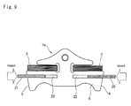
- the insertion groove 19 may also be divided into two insertion grooves 22 and 23. That is, the insertion groove may be formed without penetrating through the adjuster element 1b laterally from the end face 4 to the end face 5.
- the driving belt B is assembled by fastening the plurality of standard elements 1a and the adjuster element(s) 1b thus structured using the rings 2 and 3.
- the driving belt B is assembled by forming an element array by juxtaposing at least one adjuster element 1b before inserting the inserting member 18 into the insertion groove 19, and predetermined pieces of the standard element 1a in the same orientation and in a circular manner.
- the rings 2 and 3 are individually inserted into the slits 9 and 10 of the standard elements 1a and the adjuster element(s) 1b thus forming the element array thereby fastening the element array.
- the inserting member 18 is inserted into the insertion groove 19 of the adjuster element 1b to fill in the endplay in the aligning direction of the element array.
- dimensions of the inserting member 18 are determined taking into consideration a distance of the endplay. Therefore, the endplay in the driving belt B can be reduced ideally to substantially zero by inserting the inserting member 18 thus designed into the insertion groove 19 as shown in Figs. 7 to 9 .
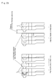
- Fig. 10 shows an example of forming the insertion groove for inserting the inserting member thereto also in the head portion 8 of the adjuster element 1b, in addition to the base portion 6. That is, the examples shown in Figs. 3 to 7 are configured to fill in the endplay only at the level in the vicinity of the level at which the rocking edge 17 of the standard element 1a is situated, by forming the insertion groove 19 only on the base portion 6 of the adjuster element 1b. Meanwhile, according to an example shown in Fig. 10 , a pair of insertion grooves 24 and 25 is formed on the head portion 8 in addition to the insertion groove 19 formed on the base portion. Therefore, for the purpose of reducing the endplay, an inserting member 26 is inserted into the insertion groove 24, and, an inserting member 27 is inserted into the insertion groove 25.
- the insertion grooves 24 and 25 are formed on the front face 15 of the head portion 8 of the adjuster element 1b.
- those insertion grooves 24 and 25 are formed to open to the front face 15, and the cross-section thereof is individually rectangular. More specifically, the insertion groove 24 is formed from one of the sides of the projection 13 to open also to an end face 8a. Meanwhile, the insertion groove 25 is formed from the other side of the projection 13 to open also to an end face 8b.
- each inserting member 26 and 27 is also a rod-like member whose cross-section is substantially rectangular, which is made of the same metal material as the standard element 1a and the adjuster element 1b, or which is made of other materials having strength or hardness similar to that of the standard element 1a and the adjuster element 1b.
- the inserting member 26 also comprises an engaging portion inserted into the insertion groove 24, and a contact face contacted with the element being opposed to the adjuster element 1b holding the inserting members 26 and 27 across the endplay.
- the inserting member 27 also comprises an engaging portion inserted into the insertion groove 25, and a contact face contacted with the element being opposed to the adjuster element 1b holding the inserting members 26 and 27 across the endplay.
- the driving belt B may also be assembled by fastening the plurality of standard elements 1a and the adjuster element(s) 1b as illustrated in Fig. 10 using the rings 2 and 3.
- the driving belt B may also be assembled by forming an element array by juxtaposing at least one adjuster element 1b shown in Fig. 10 and predetermined pieces of the standard element 1a in the same orientation and in a circular manner. Then, the element array of the standard elements 1a and the adjuster element(s) 1b is fastened by the rings 2 and 3. Thereafter, the inserting member 18 is inserted into the insertion groove 19, the inserting member 26 is inserted into the insertion groove 24, and the inserting member 27 is inserted into the insertion groove 25. As a result, the endplay in the aligning direction of the driving belt B can be reduced.
- the adjuster element 1b shown in Fig. 10 is contacted with the adjacent element E at two different levels, that is, at the level where the inserting member 18 is situated and at the level where the inserting member 26 and 27 are situated. For this reason, an attitude of the adjuster element 1b in the element array can be stabilized.
- the endplay in the driving belt B is reduced by inserting the inserting member at two different levels of the adjuster element 1b. Consequently, the adjuster element 1b is allowed to serve as the standard element 1a, and the stability of the driving belt B can be improved.
- the inserting member and insertion groove may also be arranged on the rear face 16 of the adjuster element 1b.
- the examples shown in in Figs. 3 to 7 and 10 are configured to form the insertion groove 19 (or 24 and 25) on the front face 15 of the adjuster element 1b. That is, those insertion groove(s) is/are formed on the same face of the adjuster element 1b as the face of the standard element 1a in the aligning direction of the element array on which the rocking edge 17 is formed, and the inserting member(s) is/are inserted into the insertion groove(s) to fill in the endplay.
- Figs. 11 and 12 the inserting member and insertion groove may also be arranged on the rear face 16 of the adjuster element 1b.
- the examples shown in in Figs. 3 to 7 and 10 are configured to form the insertion groove 19 (or 24 and 25) on the front face 15 of the adjuster element 1b. That is, those insertion groove(s) is/are formed on the same face of the adjuster element 1
- an insertion groove 28, and insertion grooves 29 and 30 are formed on the rear face 16 of the adjuster element 1b, that is, on the face opposite to the face of the standard element 1a in the aligning direction of the element array on which the rocking edge 17 is formed.
- an inserting member 31 is inserted into the insertion groove 28, and inserting members 32 and 33 are inserted into the insertion grooves 29 and 30 respectively to fill in the endplay.
- the insertion groove 28 is formed on the rear face 16 of the adjuster element 1b.
- the cross-section of the insertion groove 28 is also rectangular, therefore, the insertion groove 28 is open to the rear face 16, and also open to both of the end faces 4 and 5 thereby allowing the inserting member 31 to be inserted therein from the end face 4 (or 5) widthwise.
- the insertion groove 28 is formed on the adjuster element 1b at a level in the vicinity of the level of the rocking edge 17 of the standard element 1a juxtaposed in the element array.
- the rocking edge 17 is formed on the front face 15 of the adjuster element 1b, that is, on the same face as the face of the standard element 1a in the aligning direction of the element array on which the rocking edge 17 is formed.
- the inserting member 31 is also a rod member whose cross-section is rectangular as the aforementioned inserting members 18, 26 and 27, and also made of same metal material as the standard element 1a and the adjuster element 1b, or other materials having strength or hardness similar to that of the standard element 1a and the adjuster element 1b. As shown in Fig. 12 , the inserting member 31 comprises an engaging portion 31a inserted into the insertion groove 28 to be engaged with the adjuster element 1b, and a contact face 31b to be contacted with the element being opposed to the adjuster element 1b holding the inserting member 31 across the endplay.
- the contact face 31b includes a flat face 31c.
- the flat face 31b is formed in a manner to be contacted with the rocking edge 17 of the element opposed thereto, and to be parallel with the opposite face of the element opposed thereto on which the rocking edge 17 is not formed, in case the inserting member 31 is inserted into the insertion groove 28 to fill in the endplay. Therefore, the adjuster element 1b is allowed to serve as the standard element 1a having the rocking edge 17 by inserting the inserting member 31 is into the insertion groove 28.
- the insertion grooves 29 and 30 are formed on the rear face 16 of the head portion 8 of the adjuster element 1b in a manner to open to the rear face 16 side, and a cross-section thereof is also rectangular.
- the insertion groove 29 is formed from one of the sides of the hole 14 to open also to one of the end faces of the head portion 8.
- the insertion groove 30 is formed from the other side of the hole 14 to open also to the other end face of the head portion 8.
- each inserting member 32 and 33 is also a rod member whose cross-section is substantially rectangular made of the same metal material as the standard element 1a and the adjuster element 1b, or other materials having strength or hardness similar to that of the standard element 1a and the adjuster element 1b.
- the inserting member 32 also comprises an engaging portion 32a inserted into the insertion groove 29, and a contact face 32b contacted with the element being opposed to the adjuster element 1b holding the inserting member 32 across the endplay.
- the inserting member 33 also comprises an engaging portion 33a inserted into the insertion groove 30, and a contact face 33b contacted with the element being opposed to the adjuster element 1b holding the inserting member 33 across the endplay.
- the driving belt B may also assembled by fastening the plurality of standard elements 1a and the adjuster element(s) 1b as illustrated in Figs. 11 and 12 using the rings 2 and 3.
- the driving belt B may also be assembled by forming an element array by juxtaposing at least one adjuster element 1b shown in Figs. 11 and 12 before inserting the inserting members 31, 32 and 33 into the insertion grooves 28, 29 and 30, and predetermined pieces of the standard element 1a in the same orientation and in a circular manner. Then, the element array of the standard elements 1a and the adjuster element(s) 1b is fastened by the rings 2 and 3.
- the inserting member 31 is inserted into the insertion groove 28
- the inserting member 32 is inserted into the insertion groove 29
- the inserting member 33 is inserted into the insertion groove 30.
- the adjuster element 1b shown in Figs. 11 and 12 is contacted with the adjacent element E at two different levels, that is, at the level where the inserting member 31 is situated and at the level where the inserting member 32 and 33 are situated, as the example shown in Fig. 10 .
- the insertion groove 28 to which the inserting member 31 is inserted is formed on the rear face 16 of the adjuster element 1b.
- the inserting member 31 is not required to function as a rocking edge so that it is unnecessary to form a curved face or an edge on the contacting face 31b.
- the driving belt B can be manufactured easily in comparison with a case in which the curved face or edge is formed on the contacting face 31b.
- Fig. 13 shows an example of preventing a disengagement of the inserting member from the insertion groove of the adjuster element 1b by engaging the inserting member with the insertion groove.
- the inserting member whose cross-section is rectangular is inserted into the insertion groove whose cross-section is also rectangular.
- a cross-section of each inserting member 34, 35 and 36 is T-shape, and the inserting members 34, 35 and 36 are inserted into insertion grooves 37, 38 and 39 respectively.
- the inserting member 34 is a rod member whose cross-section is T-shape.
- the inserting member 34 is also made of the same metal material as the standard element 1a and the adjuster element 1b, or other materials having strength or hardness similar to that of the standard element 1a and the adjuster element 1b.
- the inserting member 34 comprises an engaging portion 34a inserted into the insertion groove 37, and a contact face 34b contacted with the element being opposed to the adjuster element 1b holding the inserting member 34 across the endplay.
- an edge portion 34c is formed on the contact face 34b. Therefore, the edge portion 34c serves as a rocking edge as the aforementioned rocking edge 17 under the situation in which the inserting member 34 is inserted into the insertion groove 37 to fill in the endplay.
- the insertion groove 37 to which the inserting member 34 is inserted is formed on the base portion 6 of the adjuster element 1b, and a cross-section thereof is also T-shape.
- the insertion groove 37 comprises a engaging groove 37a to which the engaging portion 34a of the inserting member 34 is inserted, and an opening portion 37b opening toward the front face 15 whose opening width is narrower than a groove width of the engaging groove 37a.
- the insertion groove 37 is formed as a dovetail groove whose cross-section is T-shape.
- the insertion groove 37 is also open to both lateral ends as shown in Fig. 13 .
- the insertion groove 37 may also be formed into a common dovetail groove having a trapezoidal cross-section.
- the engaging member 34a of the inserting member 34 is formed to have a trapezoidal cross-section to be fitted into the insertion groove 37.
- the insertion groove 37 is formed on the adjuster element 1b on the same side as the face of the standard element 1a on which the rocking edge 17 is formed, in the aligning direction of the element array.
- the insertion groove 37 is formed at a level in the vicinity of the level at which the rocking edge 17 is formed on the standard element 1a. Therefore, the adjuster element 1b is allowed to serve as the standard element 1a having the rocking edge 17 by inserting the inserting member 37 thus having the edge portion 34c into the insertion groove 37.
- the insertion grooves 38 and 39 are formed on the head portion 8 of the adjuster element 1b, and the inserting members 35 and 36 are inserted respectively thereto.
- the inserting member 35 comprises an engaging portion 35a which is inserted into the insertion groove 38 to be engaged with the adjuster element 1b, and a contact face 35b which is contacted with the element being opposed to the adjuster element 1b holding the inserting member 35 across the endplay.
- the inserting member 36 comprises an engaging portion 36a which is inserted into the insertion groove 39 to be engaged with the adjuster element 1b, and a contact face 36b which is contacted with the element being opposed to the adjuster element 1b holding the inserting member 36 across the endplay.
- the insertion grooves 38 and 39 are formed respectively on the front face 15 of the head portion 8 of the adjuster element 1b.
- the insertion groove 38 comprises an engaging groove 38a to which the engaging portion 35a of the inserting member 35 is inserted, and an opening portion 38b opening toward the front face 15 whose opening width is narrower than a groove width of the engaging groove 38a.
- the insertion groove 38 is formed as a dovetail groove whose cross-section is T-shape.
- the insertion groove 39 also comprises an engaging groove 39a to which the engaging portion 36a of the inserting member 36 is inserted, and an opening portion 39b opening toward the front face 15 whose opening width is narrower than a groove width of the engaging groove 39a.
- the insertion groove 39 is formed as a dovetail groove whose cross-section is T-shape.
- the insertion groove 38 is formed from one of the sides of the projection 13 to open also to an end face 8a.
- the insertion groove 39 is formed from the other side of the projection 13 to open also to an end face 8b.
- the insertion grooves 38 and 39 may also be formed respectively into a common dovetail groove having a trapezoidal cross-section.
- the engaging portions 35a and 35b of the inserting members 35 and 36 are formed to have a trapezoidal cross-section respectively to be fitted into the insertion groove 38 and 39.
- the driving belt B may also assembled by fastening the plurality of standard elements 1a and the adjuster element(s) 1b as illustrated in Fig. 13 using the rings 2 and 3.
- the driving belt B may also be assembled by forming an element array by juxtaposing at least one adjuster element 1b shown in Fig. 13 before inserting the inserting members 34, 35 and 36 into the insertion grooves 37, 38 and 39, and predetermined pieces of the standard element 1a in the same orientation and in a circular manner. Then, the element array of the standard elements 1a and the adjuster element(s) 1b is fastened by the rings 2 and 3.
- the inserting member 34 is inserted into the insertion groove 27
- the inserting member 35 is inserted into the insertion groove 38
- the inserting member 36 is inserted into the insertion groove 39.
- the inserting members 34, 35 and 36 inserted respectively into the inserting members 34, 35 and 36 to fill in the endplay in the driving belt B can be engaged respectively therewith. Therefore, the inserting members 34, 35 and 36 can be prevented from being disengaged from the adjuster element 1b shown in Fig. 13 after assembling the driving belt B by fastening the array of the adjuster element 1b and the standard element 1a using the rings 2 and 3. For this reason, the driving belt B can be manufactured rigidly while reducing the endplay thereof ideally.
- the adjuster element 1b shown in Fig. 13 is contacted with the adjacent element E at two different levels, that is, at the level where the inserting member 34 is situated and at the level where the inserting member 35 and 36 are situated, as the example shown in Fig. 10 . Therefore, an attitude of the adjuster element 1b in the element array can be stabilized.
- the example shown in Fig. 13 is configured to prevent a detachment of each inserting members 34, 35 and 36 from the adjuster element 1b thus structured in the aligning direction of the array of the elements E, by engaging the inserting members 34, 35 and 36 with the insertion grooves 37, 38 and 39 respectively.
- the adjuster element shown 1b shown in Fig. 13 comprises an "disengagement preventing means" of the present invention, which prevents disengagement of the inserting members 34, 35 and 36 from the insertion grooves 37, 38 and 39, by engaging the inserting members 34, 35 and 36 with the insertion grooves 37, 38 and 39 respectively.
- the "disengagement preventing means" may also be configured to prevent disengagement of the inserting member from the insertion groove in the width direction of the adjuster elements 1b.
- a projection 40 is formed wedgewise on a bottom face 37c of the insertion groove 37.
- the projection 40 comprises an inclined face 40a rising gradually from the bottom face 37c in an inserting direction of the inserting member 34, and an engagement face 40b configured to be engaged with an after-mentioned engagement hole 41 of the inserting member 34.
- the engagement hole 41 is formed on the engaging portion 34a of the inserting member 34 in a manner to be opposed to the bottom face 37c.
- the engagement hole 41 is configured to accommodate the projection 40 therein, and an engagement face 41a is formed therein. Therefore, the inserting member 34 is engaged with the engagement face 40b of the projection 40 at the engagement face 41a under the condition in which the inserting member 34 is inserted into the insertion groove 37 completely.
- Fig. 18 shows an example of forming the projection 40 on the insertion groove 37, and forming the engagement hole 41 on the inserting member 34 respectively.
- disengagement of the inserting member 35 from the insertion groove 38 in the inserting direction may also be prevented by forming the projection 40 on the insertion groove 38 while forming the engagement hole 41 on the inserting member 35.
- disengagement of the inserting member 36 from the insertion groove 39 in the inserting direction may also be prevented by forming the projection 40 on the insertion groove 39 while forming the engagement hole 41 on the inserting member 36.
- two pairs of projection 40 and engagement hole 41 are provided in the example shown in Fig.
- the inserting member 34 can be engaged with the insertion groove 37 by forming at least one pair of projection 40 and the engagement hole 41 at a portion where the those elements are engaged to each other under the condition in which the inserting member 34 is inserted into the insertion groove 37 completely.
- a stopper portion 42 is formed on one of the end portion of the insertion groove 37 (i.e., on the end face 5 side in Fig. 19 ), and a projection 43 is formed wedgewise on the other end of the insertion groove 37 (i.e., on the end face 4 side in Fig. 19 ). Therefore, a front end face 34d of the inserting member 34 is stopped by the stopper portion 42 when inserted into the insertion groove 37.
- the stopper portion 42 can be formed by closing the insertion groove 37 at the side of the end face 5.
- the projection 43 comprises an inclined face 43a rising gradually from the bottom face 37c in the inserting direction of the inserting member 34, and an engagement face 43b configured to be engaged with an after-mentioned engagement end 45 of the inserting member 43.
- the engaging portion 34a of the inserting member 34 comprises a guide groove 44 opening toward the bottom face 37c, and the engagement end 45 configured to be engaged with the projection 43.
- the guide groove 44 is fitted onto the projection 43 thereby guiding the inserting member 34 along the projection 43.
- the guide groove 44 is formed to be opened toward the front end face 34d in the inserting direction of the inserting member 34, and closed at the rear end face 34e side. Therefore, the engagement end 45 is formed between an end face of the guide groove 44 of the rear end face 34e side and the rear end face 34e.
- a contacting face 45a is formed on the engagement end 45, which is engaged with the engagement face 43b of the projection 43 under the condition in which the inserting member 34 is inserted into the insertion groove 37 completely.
- Fig. 19 shows an example of forming the guide groove 44 on the inserting member 34, and forming the stopper portion 42 and the projection 43 on the insertion groove 37 respectively.
- detachment of the inserting member 35 from the insertion groove 38 in the inserting direction may also be prevented by forming the guide groove 44 in the inserting member 35, while forming the stopper portion 42 and the projection 43 on the insertion groove 38.
- detachment of the inserting member 36 from the insertion groove 39 in the inserting direction may also be prevented by forming the guide groove 44 in the inserting member 36, while forming the stopper portion 42 and the projection 43 on the insertion groove 39.
- FIG. 21 Still another example of the "disengagement preventing means" is shown in Fig. 21 .
- the example shown in Fig. 21 is configured to prevent disengagement of the inserting member 18 whose cross-section is rectangular shown in Figs. 3 , 4 and 10 etc. from the adjuster element 1b having the insertion groove 19 to which the inserting member 18 is inserted, in both aligning direction and width direction of the element E.
- an engagement projection 46 is formed on a bottom face 19a of the insertion groove 19.
- the engagement projection 46 comprises a column 46a projecting integrally from the bottom face 19a, and an engagement head 46b which is diametrically larger than the column 46a and which is inserted into the an after-mentioned engagement hole 47 of the inserting member 18.
- the engagement projection 46 may be made of elastic member having a predetermined elasticity and fixed integrally to the bottom face 19a.
- the engagement hole 47 is formed on the engaging portion 18a of the inserting member 18 in a manner to open to the bottom face 19a.
- the engagement hole 47 is configured to be engaged with the engagement projection 46 under the condition in which the inserting member 18 is inserted into the insertion groove 19 completely.
- the engagement hole 47 comprises: an opening 47a, which is diametrically larger than the column 46a but diametrically smaller than the maximum outer diameter of the engagement head 46b; and a holding space 47b, which is diametrically larger than an inner diameter of the opening 47a, and which is engaged with the engagement head 46b.
- the "disengagement preventing means" of the present invention may also be formed by narrowing the width of the insertion groove partially to be narrower than the engagement portion of the inserting member inserted thereto, otherwise, by widening the width of the engagement portion of the inserting member to be inserted into the insertion groove partially to be wider than the insertion groove.
- the "disengagement preventing means" of the present invention may also be formed by increasing a friction coefficient of the insertion groove partially to increase a friction between the insertion groove and the engagement portion of the inserting member inserted thereto, otherwise, by increasing a friction coefficient of the engagement portion of the inserting member partially to increase a friction between the insertion groove and the engagement portion inserted thereto.
- the driving belt B may also be assembled easily by fastening the plurality of elements E including the adjuster element(s) 1b thus structured using the rigs 2 and 3, while adjusting the endplay in the driving belt B.
- the driving belt B is assembled by forming an element array by juxtaposing at least one adjuster element 1b before inserting the inserting member 18 shown in Figs. 3 , 4 and etc. into the insertion groove 19, and predetermined pieces of the standard element 1a in the same orientation and in a circular manner. All of the desired number of standard elements 1a and the adjuster element(s) 1b can be fastened easily by the rings 2 and 3, before reducing the endplay in the aligning direction of the element array thus formed.
- the inserting member(s) 18 is/are inserted into the endplay in the element array to fill in the endplay.
- dimensions of the inserting member 18 are determined taking into consideration a distance of the endplay. Therefore, the endplay in the driving belt B can be ideally reduced to substantially zero.
- the driving belt B can be assembled easily without degrading the power transmitting efficiency by thus using the adjuster element 1b. In other words, both of the easiness of assembling the driving belt B and the power transmitting efficiency of assembling the driving belt B can be improved.
- the assembling method of the driving belt comprises an aligning step (Process P1), an assembling step (Process P2), and an endplay adjusting step (Process P3).
- a plurality of the standard element 1a and at least one adjuster element 1b before inserting the inserting member into the insertion groove are juxtaposed by inserting the projection 13 of the element E into the hole 14 of the adjoining element.
- a predetermined number of the standard elements 1a and the adjuster element(s) 1b are prepared to assemble the driving belt. That is, a total required number of the element E including the standard elements 1a and at least one adjuster element 1b before inserting the inserting member into the insertion groove are prepared.
- those standard elements 1a and the adjuster element(s) 1b are juxtaposed in a same orientation and in a same direction thereby inserting the projection 13 into the hole 14 of the adjoining element respectively.
- the predetermined number of the standard elements 1a and the adjuster element(s) 1b are juxtaposed along one of the rings 2 and 3 (e.g., the ring 3) in a circular manner using an aligning tool or the like.
- the element array is required to contain at least one adjuster element 1b.
- a plurality of adjuster elements 1b may also be used in the element array.
- the standard elements 1a and the adjuster elements 1b are juxtaposed in a manner to situate the adjuster elements 1b at equal intervals in the length direction of the driving belt B.
- the array of the elements E consisting of the standard elements 1a and the adjuster element(s) 1b thus aligned at the above-explained aligning step is fastened by the rings 2 and 3.
- the ring 3 is inserted into the slit 10 of the elements E to align the element array in a circular manner.
- the ring 2 is inserted into the other slit 9 of the elements E thus aligned.
- the standard elements 1a and the adjuster element(s) 1b are fastened by the rings 2 and 3 in a circular manner.
- an endplay remains inevitably in the element array of the standard elements 1a and the adjuster element(s) 1b thus fastened by the rings 2 and 3, in the aligning direction of the elements, that is, in the length direction of the rings 2 and 3.
- the endplay in the driving belt B is too large, a slippage between the element E and the rings 2 and 3 is increased when the driving belt B applied to the pulley P is subjected to a load. As a result, a transmission loss resulting from the slippage is increased. Therefore, the endplay in the driving belt B is preferably reduced as small as possible. According to the assembling method of the present invention, such endplay is reduced at the subsequent endplay adjusting step using the above-explained adjuster element 1b.
- the endplay adjusting step includes an end play measuring step (Process P3-1), an inserting member selecting step (Process P3-2) and an inserting member inserting step (Process P3-2).
- the endplay measuring step is carried out to measure the endplay in the aligning direction of the element array fastened in a circular manner by the rings 2 and 3. Specifically, clearances between the adjacent elements E in the element array is collected in a clearance between the front face 15 of (one of) the adjuster element(s) 1b and the rear face 16 of the adjoining element, or in a clearance between the rear face 16 of (one of) the adjuster element(s) 1b and the front face 15 of the adjoining element. Then, a distance of the endplay thus corrected is measured. For example, the endplay thus corrected can be measured easily by using a clearance gauge or specific measuring apparatus.
- the inserting member selecting step is carried out to determine a thickness of the inserting member to be inserted into the insertion groove of the adjuster element 1b based on the actual length of the endplay measured at the endplay measuring step.
- the inserting member of the adjuster element 1b can be selected from plural different types of inserting members having different thicknesses in the direction of the endplay represented by "t" in Figs. 5 , 12 , 14 and 16 . Therefore, the inserting member having a thickness appropriate to reduce the endplay of the assembled driving belt B to a target value is selected based on the measured actual value of the endplay.
- the target value of the endplay may be determined to a most appropriate value in advance from experiment or experience.
- the thicknesses of the inserting member to be selected according to the measured actual value of the endplay can be calculated in advance taking into consideration the measured actual value of the endplay and deformation of rings 2 or 3, and tabulated or stored in a computer program.
- the inserting member selected at the inserting member selecting step is inserted into the insertion groove of the adjuster element 1b in the element array fastened in a circular manner to fill in the endplay. Consequently, the assembling work of the driving belt B is completed. Specifically, the inserting member having a thickness selected at the inserting member selecting step is inserted into the insertion groove from one of the end faces 4 and 5 of the adjuster element 1b to fill in the endplay.
- the inserting member 18 is inserted into the insertion groove 19 from one of the and face 4 and 5 to fill in the endplay.
- the inserting members 20 is inserted into insertion groove 19 from the end face 4 side, and the inserting members 21 is inserted into insertion groove 19 from the end face 5 side simultaneously or sequentially.
- the adjuster element 1b shown in Fig. 8 in which the inserting member is divided into the inserting members 20 and 21, the inserting members 20 is inserted into insertion groove 19 from the end face 4 side, and the inserting members 21 is inserted into insertion groove 19 from the end face 5 side simultaneously or sequentially.
- the inserting member 34 is inserted into the insertion groove 37 from one of the end faces 4 and 5 to fill in the endplay, and in addition, the inserting member 35 is inserted into the insertion groove 38 and the inserting member 36 is inserted into the insertion groove 39 simultaneously or sequentially.
- the assembling work of the driving belt B is completed.
- the inserting member inserted completely into the insertion groove is kept engaged with the insertion groove by the friction acting therebetween and the friction acting between the inserting member and the adjoining element E contacted thereto.
- a disengagement of the inserting member from the insertion groove may also be prevented by welding the inserting member with the insertion groove or using adhesive agent.
- the inserting member 34 is engaged with the insertion groove 37 by inserting the inserting member 34 into the insertion groove 37 completely.
- the inserting member 18 is engaged with the insertion groove 19 by inserting the inserting member 18 into the insertion groove 19 completely. Therefore, disengagement of the inserting member from the insertion groove can be prevented certainly in those cases.
- the driving belt B can be assembled easily while adjusting the endplay therein, by using the above-explained adjuster element 1b in the array of elements E fastened by the rings 2 and 3 in a circular manner.
- the array of the standard elements 1a including the adjuster element(s) 1b shown in Figs. 3 , 4 and etc. juxtaposing in a circular manner is fastened by rings 2 and 3 before inserting the inserting member 18 into the insertion groove 19 of the adjuster element 1b. Therefore, all of the elements in the element array can be fastened easily by the rigs 2 and 3 under the condition in which the endplay is still remaining in the aligning direction.
- the endplay can be reduced by inserting the inserting member 18 into the insertion groove 19 of the adjuster element 1b.
- the dimensions of the inserting member 18 are determined taking into consideration the distance of the endplay so that the endplay in the driving belt B can be reduced to substantially zero.
- the driving belt B can be assembled easily without deteriorating the power transmitting efficiency thereof by using the element E of the present invention including the adjuster element 1b and the basic element 1a. That is, the driving belt B having a preferable transmitting efficiency can be formed easily and efficiently.
- the present invention should not be limited to the examples thus far explained.
- the driving belt B has been explained to be applied to the continuously variable transmission for vehicles.
- the driving belt B and the assembling method thereof according to the present invention may also be applied to another kind of transmission mechanism comprising a belt and pulleys (i.e., to a belt transmission), and to an assembling method thereof.
- the element E having a conventional configuration in which the slits and the saddle face for holding the two rings fastening the element array annularly are formed on both side of the element E in its width direction (i.e., in the width direction of the driving belt B) is used to form the driving belt B.
- the driving belt B according to the present invention should not be limited to the above-explained structure. That is, the present invention may be applied to all kinds of driving belts formed by fastening a plurality of elements by an annular flat belt.
- the present invention may also be applied to a driving belt using an element in which a recess and a saddle face for holding the ring fastening the element array annularly is formed in a width center of the element.
Landscapes
- Engineering & Computer Science (AREA)
- General Engineering & Computer Science (AREA)
- Mechanical Engineering (AREA)
- Devices For Conveying Motion By Means Of Endless Flexible Members (AREA)
- Transmissions By Endless Flexible Members (AREA)
- Automatic Assembly (AREA)
Abstract
Description
- This invention relates to a driving belt formed by fastening a plurality of plate-like elements juxtaposed in a same orientation annularly by a flat ring, and to an assembling method thereof.
- A push type driving belt to be used in a belt type continuously variable transmission is known in the prior art. The driving belt of this kind is formed by annularly juxtaposing a plurality of plate members called an "element" or a "block" in a same orientation, and by fastening the juxtaposing plate members by an annular member such as a band, a hoop and a ring.
- One example of the above-explained driving belt is disclosed in Japanese Patent Laid-Open No.
2006-266363 2006-266363 2006-266363 - Thus, the conventional driving belt is assembled by fastening the array of the element having the projection using the ring. However, in case of inserting a last piece of the element into the array of the elements, a sufficient clearance wider than the projection is required in the element array in order to avoid interference of the projection of the element to be inserted into the element array with the adjacent element already fastened by the ring. Therefore, as shown in
Fig.23 , an endplay as a total of clearances among the elements remains inevitably in the element array of the assembled belt. However, in case the end play is too small, the last piece of the element is difficult to be inserted into the element array and easiness or productivity of the driving belt is thereby degraded. To the contrary, in case the end play is large, the last piece of the element is easy to be inserted into the element array. In this case, however, a transmission loss is increased due to a slippage between the elements and the ring, and a power transmitting efficiency is thereby degraded. - The last piece of the element can be inserted into the element array easily by shortening the projection even if the endplay is narrow. However, a fundamental role of the projection and the hole is to align the elements being juxtaposed. Therefore, if the length of the projection is too short, the element array cannot be aligned. In addition, durability and transmission efficiency of the driving belt may be degraded.
- In order to solve the problems concerning the end play of the driving belt, Japanese Patent Laid-Open No.
2004-293634 2004-293634 - However, according to the teachings of Japanese Patent Laid-Open No.
2004-293634 - Therefore, the conventional driving belt thus formed by fastening a plurality of elements annularly by a ring has to be improved to facilitate the assembling work thereof by ensuring the endplay appropriately, while reducing the endplay to improve the power transmitting efficiency thereof.
- The present invention has been conceived noting the technical problems thus far described, and its object is to provide a driving belt having an excellent power transmitting efficiency, which can be assembled easily, and in which an endplay thereof can be adjusted when assembling the driving belt by fastening element using rings. Another object of the present invention is to provide an assembling method of the above-explained driving belt.
- In order to achieve the above-mentioned object, according to the present invention, there is provided a driving belt comprising a plurality of plate elements juxtaposed in its thickness direction, and a flat ring which fastens the elements in a circular manner. According to the present invention, the plurality of elements includes at least one adjuster element, which is configured to adjust an endplay as a total of clearances between the adjacent elements in the elements fastened by the ring in a circular manner. Specifically, the adjuster element comprises an insertion groove opening toward the endplay, and an inserting member which is inserted into the insertion groove and configured to protrude partially from the insertion groove thereby adjusting the endplay.
- According to the present invention, the insertion groove of the adjuster element is formed on a face of a same side as a face of the other element on which a rocking edge is formed, at a level in the vicinity of a level at which the rocking edge is situated. Meanwhile, the inserting member comprises an edge portion, which is formed on a face to be opposed to the adjacent other element in case the inserting member is inserted into the insertion groove, and which is configured to serve as the rocking edge in case the inserting member is inserted into the insertion groove.
- Alternatively, the rocking edge may also be formed on the adjuster element as that of the other elements. In this case, the insertion groove of the adjuster element is formed on a face opposite to a face of the other element on which a rocking edge is formed, at a level in the vicinity of a level at which the rocking edge is situated. Meanwhile, a flat face is formed on the inserting member. Specifically, the flat face is formed to be opposed to the adjoining other element in case the inserting member is inserted into the insertion groove, and to be in parallel with a face of the adjoining other element on which the rocking edge is not formed.
- Specifically, the insertion groove includes a first insertion groove formed at the level in the vicinity of the level at which the rocking edge of the other element is situated, and a second insertion groove formed on a head portion of the adjuster element situated in an outer circumferential side of the elements fastened in a circular manner. Meanwhile, the inserting member includes a first inserting member to be inserted into the first insertion groove, and a second inserting member to be inserted into the second insertion groove.
- In addition, according to the present invention, at least one of the inserting member and the insertion groove comprises a disengagement preventing means, which is configured to engage the inserting member with the insertion groove in case the inserting member is inserted into the insertion groove thereby preventing a disengagement of the insertion member from the insertion groove.
- According to another aspect of the present invention, there is provided an assembling method of a driving belt comprising an aligning step of juxtaposing a plurality of plate elements in its thickness direction, and an assembling step of fastening an array of the elements juxtaposed at the aligning step in a circular manner. Specifically, at the aligning step, at least one adjuster element is aligned in an array of the elements before inserting the inserting member into the insertion groove. The assembling method further comprises an endplay adjusting step of reducing an endplay after the assembling step, by inserting the inserting member into the insertion groove.
- According to the present invention, therefore, the driving belt can be assembled easily while adjusting the endplay thereof when fastening the elements in a circular manner by the ring. Specifically, the driving belt is assembled by forming an element array by juxtaposing the elements using at least one adjuster element before the inserting member into the insertion groove. Therefore, all of the elements including the adjuster element can be fastened easily by the ring before reducing the endplay in the aligning direction of the element array. After thus fastening all of the elements including the adjuster element, the endplay is reduced by inserting the inserting member into the insertion groove. For this purpose, dimensions of the inserting member are determined taking into consideration a distance of the endplay so that the endplay can be reduced to substantially zero. As a result of thus reducing the endplay, a transmission loss resulting from a slippage between the element and the ring can be reduced so that the power transmitting efficiency of the driving belt is improved. Thus, according to the present invention, the driving belt can be assembled easily without degrading the power transmitting efficiency.
- As described, the edge portion is formed on the inserting member. Therefore, in case of reducing the endplay by inserting the inserting member into the insertion groove of the adjuster element, the edge portion of the inserting member is contacted with a flat face of the adjoining element to serve as the rocking edge. Thus, the adjuster element serves as the other elements having the rocking edge.
- Alternatively, a flat face may also be formed on the inserting member. In this case, the flat face formed on the inserting member is contacted with the rocking edge of the adjoining element under the situation in which the inserting member is inserted into the insertion groove of the adjuster element to reduce the endplay. That is, the flat face serves as a receiving face of a reaction force from the rocking edge. Therefore, the adjuster element serves as the other elements. Further, the flat face may be formed easily on the inserting member in comparison with forming a curved face or an edge thereon. For this reason, according to the present invention, the driving belt can be manufactured easily
- As also described, according to the driving belt of the present invention, the second insertion groove may be formed on the head portion of the adjuster element situated in the outer circumferential side, in addition to the first insertion groove formed at the level in the vicinity of the level at which the rocking edge of the other element is situated. In this case, the first inserting member is inserted into the first insertion groove, and the second inserting member is inserted into the insertion groove. That is, the adjuster element is contacted with the adjoining element at two different levels. Therefore, the attitude of the adjuster element in the element array can be stabilized. In other words, the adjuster element can be contacted with the adjoining element in a same condition as the other elements. Thus, the adjuster element serves as the other elements also in this case.
- In addition, according to the present invention, the adjuster element further comprises the disengagement preventing means configured to engage the inserting member inserted into the insertion groove with the insertion groove in case the inserting member is inserted into the insertion groove to reduce the endplay. Therefore, the inserting member can be prevented from being disengaged from the adjuster element even after fastening the elements by the ring.
- Meanwhile, according to the assembling method of the present invention, the driving belt is assembled using the adjuster element thus structured together with the other standard elements. Therefore, the driving belt can be assembled easily, that is the productivity of the driving belt can be improved, while improving a power transmitting efficiency.
-
-
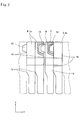
Fig. 1 is a front view schematically showing a structure of a standard element and a cross-section of a ring forming the driving belt of the present invention. -
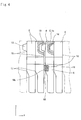
Fig. 2 is a side view (or partial sectional view) schematically showing a structure of the standard elements forming the driving belt of the present invention. -
Fig. 3 is a front view schematically showing a structure of an adjuster element and a cross-section of the ring forming the driving belt of the present invention. -
Fig. 4 is a side view (or partial sectional view) schematically showing a structure of the adjuster element used in the driving belt of the present invention. -
Fig. 5 is a sectional view showing a structure of an inserting member of the adjuster element shown inFigs. 3 and4 . -
Fig. 6 is a sectional view showing a structure of an insertion groove of the adjuster element shown inFigs. 3 and4 . -
Fig. 7 is a sectional view showing a situation in which the inserting member is inserted into the insertion groove formed on the adjuster element shown inFigs. 3 and4 . -
Fig. 8 is a sectional view showing a situation in which the inserting member of another configuration is inserted into the insertion groove formed on the adjuster element shown inFigs. 3 and4 . -
Fig. 9 is a sectional view showing a situation in which the inserting member of another configuration is inserted into the insertion groove of another configuration formed on the adjuster element shown inFigs. 3 and4 . -
Fig. 10 is a front and side views schematically showing another example of the adjuster element used in the driving belt of the invention. -
Fig. 11 is a side view schematically showing still another example of the adjuster element used in the driving belt of the invention. -
Fig. 12 is a sectional view showing a structure of the inserting member of the adjuster element shown inFigs. 10 and11 . -
Fig. 13 is a front and side views schematically showing still another example of the adjuster element used in the driving belt of the invention. -
Fig. 14 is a sectional view showing a structure of the inserting member of the adjuster element shown inFig. 13 . -
Fig. 15 is a sectional view showing a structure of the insertion groove formed on the adjuster element shown inFig. 13 . -
Fig. 16 is a sectional view showing a structure of the inserting member of the adjuster element shown inFig. 13 . -
Fig. 17 is a sectional view showing a structure of the insertion groove formed on the adjuster element shown inFig. 13 . -
Fig. 18 is a view schematically showing an example of the inserting member and the insertion groove of the adjuster element to form a "disengagement preventing means". -
Fig. 19 is a view schematically showing another example of the inserting member and the insertion groove of the adjuster element to form another "disengagement preventing means". -
Fig. 20 is a view schematically showing still another example of the inserting member and the insertion groove of the adjuster element to form still another "disengagement preventing means". -
Fig. 21 is a view schematically showing still another example of the inserting member and the insertion groove of the adjuster element to form still another "disengagement preventing means". -
Fig. 22 is a process chart explaining assembling method of the driving belt using the adjuster element according to the present invention. -
Fig. 23 is a view schematically showing a basic element used in a conventional driving belt and an endplay in the aligning direction. - Next, examples of a structure of the driving belt according to the present invention will be explained hereinafter with reference to the accompanying drawings. For example, a driving belt to which the present invention is applied is used in a belt-type continuously variable transmission for a vehicle. Specifically, the driving belt is applied to a V-groove of a pulley formed between a pair of sheaves to transmit a torque by a friction force established between the belt and the pulley. A fundamental structure of the driving belt is schematically shown in
Fig. 1 to 4 . As shown inFig. 1 and3 , a driving belt B is applied to a pair of (driving and driven) pulleys P forming a transmission mechanism of the belt-type continuously variable transmission. Each pulley P is formed by a pair of fixed sheave and movable sheave being opposed to each other, and opposed faces of those sheaves are individually tapered to form a belt groove Pv between those sheaves. A width of the groove Pv is varied by reciprocating the movable sheave using an actuator such as hydraulic cylinder. - The driving belt B is formed by fastening a plurality of elements E in a circular manner by
rings standard element 1a, and anadjuster element 1b configured to adjust an endplay in an aligning direction of the element array fastened annularly by therings - The
standard element 1a is, as shown inFig. 1 ,2 and23 , a conventional element to be used mainly in the elements E forming the driving belt B. On the other hand, only one or a few pieces of theadjuster element 1b is/are used in the elements E for the purpose of adjusting the end play A fundamental structure of theadjuster element 1b is similar to that of thebasic element 1a. Specifically, thestandard element 1a andadjuster element 1b are plate member made of metal. Both lateral faces of abase portion 6, that is, both end faces 4 and 5 (in the direction of x-axis inFigs. 1 and3 ) of thebase portion 6 are inclined to conform to an inclination of the belt groove Pv of the pulley P Therefore, eachend face base portion 6 serves as a so-called flank face to be contacted frictionally with the belt grooves Pv thereby transmitting the torque between the pulley P and the driving belt B. - A
neck portion 7 extends upwardly inFigs. 1 to 4 from a width center of thebase portion 6, and ahead portion 8 is formed integrally with an upper end portion of theneck portion 7 in a manner to extend toward both lateral ends of the base portion 6 (i.e., in the direction of x-axis inFigs. 1 and3 ) like a canopy. Consequently, slits 9 and 10 opening laterally are formed on both sides of theneck portion 7 between an upper edge of thebase portion 6 and a lower edge of the head portion 8 (inFigs. 1 to 4 ).Rings slits standard element 1a and the adjuster element(s) 1b juxtaposed closely in a circular manner. That is, the upper edges of thebase portion 6 individually serve as saddle faces 11 and 12 to which inner circumferential faces 2i and 3i of therings standard element 1a and the adjuster element(s) 1b are fastened by therings - Both of the
rings rings - In order to align the adjacent elements juxtaposed in the array of the
standard element 1a andadjuster element 1b in its thickness direction (i.e., in a z-axis direction ofFigs. 2 and4 ), aprotrusion 13 and ahole 14 are formed on thehead portion 8 of each of thestandard element 1a andadjuster element 1b. Specifically, theprojection 13 is formed on one of front and rear faces in the thickness direction of the head portion 8 (e.g., on afront face 15 of the left side ofFigs. 2 and4 ) above the neck portion 7 (i.e., at a width center of the head portion 8). Meanwhile, thehole 14 to which theprojection 13 of adjoining element is inserted loosely is formed on the opposite face of the head portion 8 (e.g., arear face 16 of the right side ofFigs. 2 and4 ). Therefore, a relative position between the adjoining elements can be determined in both vertical and horizontal directions by inserting theprojection 13 into thehole 14 of the adjoining elements. - As described, the
standard element 1a and adjuster element(s) 1b are juxtaposed in a same orientation and fastened by therings elements Figs. 1 to 4 , a thickness of the element 1 is thinned at its lower portion (that is, at the portion close to the rotational center of the pulley P). - Specifically, a portion of the
front face 15 of thebase portion 6 below the saddle faces 11 and 12 (i.e., a lower portion inFigs 1 to 4 ) is depressed to be thinner than the maximum thickness of thebase portion 6. In other words, a thickness of thebase portion 6 is reduced between a portion of thefront face 15 lower than a predetermined distance from the saddle faces 11 and 12 and the lowest portion of theelement Figs. 1 to 4 ). Here, the lowest portion of thestandard element 1a or theadjuster element 1b is a portion to be closest to a rotational center of the pulley P when the element is situated around the pulley P Therefore, in case theelements element base portion 6 is thus changed functions as a rockingedge 17, which is to be contacted with arear face 16 of theadjoining element - As shown in
Figs. 3 and4 , according to the present invention, theadjuster element 1b comprises an insertingmember 18 for adjusting the endplay of the driving belt B, and aninsertion groove 19 to which the insertingmember 18 is inserted to be engaged therewith. According to the example shown inFigs. 3 and4 , the insertingmember 18 is a rod member whose cross-section is substantially rectangular. For example, the insertingmember 18 is made of a metal material used for thestandard element 1a and theadjuster element 1b. Alternatively, the insertingmember 18 may also be made of other materials having strength or hardness similar to that of thestandard element 1a and theadjuster element 1b. As shown inFig. 5 , the insertingmember 18 comprises an engagingportion 18a which is inserted into theinsertion groove 19 to be engaged with theadjuster element 1b, and acontact face 18b which is contacted with therear face 16 of the element being opposed to theadjuster element 1b holding the insertingmember 19 across the endplay. In addition, anedge portion 18c is formed on thecontact face 18b. Therefore, theedge portion 18c serves as a rocking edge as theaforementioned rocking edge 17 under the situation in which the insertingmember 18 is inserted into theinsertion groove 19 to fill in the endplay. - According to the example shown in
Figs. 3 and4 , theinsertion groove 19 is formed on thebase portion 6 in a manner to open to the endplay between theadjuster element 1b and the adjacent element in the array of the elements E fastened in a circular manner, and the insertingmember 18 whose cross-section is rectangular is inserted therein. Specifically, as shown inFig. 6 , theinsertion groove 19 opens toward thefront face 15 and a cross-section thereof is also rectangular to hold the engagingportion 18a of the insertingmember 18 therein. As shown inFig. 7 , in order to allow the insertingmember 18 to be inserted into theinsertion groove 19 laterally from the end face 4 (or 5) of theadjuster element 1b, theinsertion groove 19 is also open to both lateral ends. - More specifically, according to the examples shown in
Figs. 3 and4 , theinsertion groove 19 of theadjuster element 1b is formed on a face of the same side as the face of thestandard element 1a on which the rockingedge 17 is formed, in the aligning direction of the element array. In addition, theinsertion groove 19 is formed at a level in the vicinity of the level of the rockingedge 17 formed on thestandard element 1a. In other words, theinsertion groove 19 is formed on theadjuster element 1b at the level including the level at which the rockingedge 17 of thestandard element 1a is situated. Therefore, theedge portion 18c of theadjuster element 1b serves as the rockingedge 17 of thestandard element 1a under the condition in which the insertingmember 18 is inserted into theinsertion groove 19. Consequently, theadjuster element 1b is allowed to serve as thestandard element 1a having the rockingedge 17. - Thus,
Fig. 7 shows the example of inserting the insertingmember 18 as a single rod member penetrating from theend face 4 to theend face 5. Alternatively, as shown inFig. 8 , the inserting member may be divided into two insertingmembers member 20 is inserted into theinsertion groove 19 from theend face 4, and the insertingmember 21 is inserted into theinsertion groove 19 from theend face 5. In addition, as shown inFig. 9 , theinsertion groove 19 may also be divided into twoinsertion grooves 22 and 23. That is, the insertion groove may be formed without penetrating through theadjuster element 1b laterally from theend face 4 to theend face 5. - As described, according to the present invention, the driving belt B is assembled by fastening the plurality of
standard elements 1a and the adjuster element(s) 1b thus structured using therings adjuster element 1b before inserting the insertingmember 18 into theinsertion groove 19, and predetermined pieces of thestandard element 1a in the same orientation and in a circular manner. Then, therings slits standard elements 1a and the adjuster element(s) 1b thus forming the element array thereby fastening the element array. Thereafter, the insertingmember 18 is inserted into theinsertion groove 19 of theadjuster element 1b to fill in the endplay in the aligning direction of the element array. For this purpose, dimensions of the insertingmember 18 are determined taking into consideration a distance of the endplay. Therefore, the endplay in the driving belt B can be reduced ideally to substantially zero by inserting the insertingmember 18 thus designed into theinsertion groove 19 as shown inFigs. 7 to 9 . -
Fig. 10 shows an example of forming the insertion groove for inserting the inserting member thereto also in thehead portion 8 of theadjuster element 1b, in addition to thebase portion 6. That is, the examples shown inFigs. 3 to 7 are configured to fill in the endplay only at the level in the vicinity of the level at which the rockingedge 17 of thestandard element 1a is situated, by forming theinsertion groove 19 only on thebase portion 6 of theadjuster element 1b. Meanwhile, according to an example shown inFig. 10 , a pair ofinsertion grooves head portion 8 in addition to theinsertion groove 19 formed on the base portion. Therefore, for the purpose of reducing the endplay, an insertingmember 26 is inserted into theinsertion groove 24, and, an insertingmember 27 is inserted into theinsertion groove 25. - Specifically, as shown in
Fig. 10 , theinsertion grooves front face 15 of thehead portion 8 of theadjuster element 1b. As the above-explainedinsertion groove 19, thoseinsertion grooves front face 15, and the cross-section thereof is individually rectangular. More specifically, theinsertion groove 24 is formed from one of the sides of theprojection 13 to open also to anend face 8a. Meanwhile, theinsertion groove 25 is formed from the other side of theprojection 13 to open also to anend face 8b. - As the above-explained
insertion member 18, each insertingmember standard element 1a and theadjuster element 1b, or which is made of other materials having strength or hardness similar to that of thestandard element 1a and theadjuster element 1b. The insertingmember 26 also comprises an engaging portion inserted into theinsertion groove 24, and a contact face contacted with the element being opposed to theadjuster element 1b holding the insertingmembers member 27 also comprises an engaging portion inserted into theinsertion groove 25, and a contact face contacted with the element being opposed to theadjuster element 1b holding the insertingmembers - Therefore, according to the present invention, the driving belt B may also be assembled by fastening the plurality of
standard elements 1a and the adjuster element(s) 1b as illustrated inFig. 10 using therings adjuster element 1b shown inFig. 10 and predetermined pieces of thestandard element 1a in the same orientation and in a circular manner. Then, the element array of thestandard elements 1a and the adjuster element(s) 1b is fastened by therings member 18 is inserted into theinsertion groove 19, the insertingmember 26 is inserted into theinsertion groove 24, and the insertingmember 27 is inserted into theinsertion groove 25. As a result, the endplay in the aligning direction of the driving belt B can be reduced. - Thus, in case of using the
adjuster element 1b shown inFig. 10 to form the driving belt B, theadjuster element 1b is contacted with the adjacent element E at two different levels, that is, at the level where the insertingmember 18 is situated and at the level where the insertingmember adjuster element 1b in the element array can be stabilized. Thus, according to the example shown inFig. 10 , the endplay in the driving belt B is reduced by inserting the inserting member at two different levels of theadjuster element 1b. Consequently, theadjuster element 1b is allowed to serve as thestandard element 1a, and the stability of the driving belt B can be improved. - Alternatively, as shown in
Figs. 11 and12 , the inserting member and insertion groove may also be arranged on therear face 16 of theadjuster element 1b. As described, the examples shown in inFigs. 3 to 7 and10 are configured to form the insertion groove 19 (or 24 and 25) on thefront face 15 of theadjuster element 1b. That is, those insertion groove(s) is/are formed on the same face of theadjuster element 1b as the face of thestandard element 1a in the aligning direction of the element array on which the rockingedge 17 is formed, and the inserting member(s) is/are inserted into the insertion groove(s) to fill in the endplay. Meanwhile, according to the example shown inFigs. 11 and12 , aninsertion groove 28, andinsertion grooves rear face 16 of theadjuster element 1b, that is, on the face opposite to the face of thestandard element 1a in the aligning direction of the element array on which the rockingedge 17 is formed. In this example, therefore, an insertingmember 31 is inserted into theinsertion groove 28, and insertingmembers insertion grooves - Specifically, as shown in
Fig. 11 , theinsertion groove 28 is formed on therear face 16 of theadjuster element 1b. The cross-section of theinsertion groove 28 is also rectangular, therefore, theinsertion groove 28 is open to therear face 16, and also open to both of the end faces 4 and 5 thereby allowing the insertingmember 31 to be inserted therein from the end face 4 (or 5) widthwise. In this example, theinsertion groove 28 is formed on theadjuster element 1b at a level in the vicinity of the level of the rockingedge 17 of thestandard element 1a juxtaposed in the element array. Meanwhile, the rockingedge 17 is formed on thefront face 15 of theadjuster element 1b, that is, on the same face as the face of thestandard element 1a in the aligning direction of the element array on which the rockingedge 17 is formed. - The inserting
member 31 is also a rod member whose cross-section is rectangular as the aforementioned insertingmembers standard element 1a and theadjuster element 1b, or other materials having strength or hardness similar to that of thestandard element 1a and theadjuster element 1b. As shown inFig. 12 , the insertingmember 31 comprises an engagingportion 31a inserted into theinsertion groove 28 to be engaged with theadjuster element 1b, and acontact face 31b to be contacted with the element being opposed to theadjuster element 1b holding the insertingmember 31 across the endplay. Thecontact face 31b includes aflat face 31c. Specifically, theflat face 31b is formed in a manner to be contacted with the rockingedge 17 of the element opposed thereto, and to be parallel with the opposite face of the element opposed thereto on which the rockingedge 17 is not formed, in case the insertingmember 31 is inserted into theinsertion groove 28 to fill in the endplay. Therefore, theadjuster element 1b is allowed to serve as thestandard element 1a having the rockingedge 17 by inserting the insertingmember 31 is into theinsertion groove 28. - Meanwhile, likewise the
aforementioned insertion groove 28, theinsertion grooves rear face 16 of thehead portion 8 of theadjuster element 1b in a manner to open to therear face 16 side, and a cross-section thereof is also rectangular. Specifically, theinsertion groove 29 is formed from one of the sides of thehole 14 to open also to one of the end faces of thehead portion 8. Meanwhile, theinsertion groove 30 is formed from the other side of thehole 14 to open also to the other end face of thehead portion 8. - Likewise the above-explained
insertion members member standard element 1a and theadjuster element 1b, or other materials having strength or hardness similar to that of thestandard element 1a and theadjuster element 1b. In addition, as shown inFig. 12 , the insertingmember 32 also comprises an engagingportion 32a inserted into theinsertion groove 29, and acontact face 32b contacted with the element being opposed to theadjuster element 1b holding the insertingmember 32 across the endplay. Meanwhile, the insertingmember 33 also comprises an engagingportion 33a inserted into theinsertion groove 30, and acontact face 33b contacted with the element being opposed to theadjuster element 1b holding the insertingmember 33 across the endplay. - Therefore, according to the present invention, the driving belt B may also assembled by fastening the plurality of
standard elements 1a and the adjuster element(s) 1b as illustrated inFigs. 11 and12 using therings adjuster element 1b shown inFigs. 11 and12 before inserting the insertingmembers insertion grooves standard element 1a in the same orientation and in a circular manner. Then, the element array of thestandard elements 1a and the adjuster element(s) 1b is fastened by therings member 31 is inserted into theinsertion groove 28, the insertingmember 32 is inserted into theinsertion groove 29, and the insertingmember 33 is inserted into theinsertion groove 30. As a result, the endplay in the aligning direction of the driving belt B thus structured can be reduced. - Thus, in case of using the
adjuster element 1b shown inFigs. 11 and12 to form the driving belt B, theadjuster element 1b is contacted with the adjacent element E at two different levels, that is, at the level where the insertingmember 31 is situated and at the level where the insertingmember Fig. 10 . For this reason, an attitude of theadjuster element 1b in the element array can be stabilized. In addition, according to the example shown inFigs. 11 and12 , theinsertion groove 28 to which the insertingmember 31 is inserted is formed on therear face 16 of theadjuster element 1b. Therefore, the insertingmember 31 is not required to function as a rocking edge so that it is unnecessary to form a curved face or an edge on the contactingface 31b. For this reason, the driving belt B can be manufactured easily in comparison with a case in which the curved face or edge is formed on the contactingface 31b. -
Fig. 13 shows an example of preventing a disengagement of the inserting member from the insertion groove of theadjuster element 1b by engaging the inserting member with the insertion groove. According to the above-explained examples, the inserting member whose cross-section is rectangular is inserted into the insertion groove whose cross-section is also rectangular. On the other hand, according to the example shown inFig. 13 , a cross-section of each insertingmember members insertion grooves - Specifically, the inserting
member 34 is a rod member whose cross-section is T-shape. The insertingmember 34 is also made of the same metal material as thestandard element 1a and theadjuster element 1b, or other materials having strength or hardness similar to that of thestandard element 1a and theadjuster element 1b. As shown inFig. 14 , the insertingmember 34 comprises an engagingportion 34a inserted into theinsertion groove 37, and acontact face 34b contacted with the element being opposed to theadjuster element 1b holding the insertingmember 34 across the endplay. In addition, anedge portion 34c is formed on thecontact face 34b. Therefore, theedge portion 34c serves as a rocking edge as theaforementioned rocking edge 17 under the situation in which the insertingmember 34 is inserted into theinsertion groove 37 to fill in the endplay. - On the other hand, the
insertion groove 37 to which the insertingmember 34 is inserted is formed on thebase portion 6 of theadjuster element 1b, and a cross-section thereof is also T-shape. Specifically, as shown inFig. 15 , theinsertion groove 37 comprises a engaginggroove 37a to which the engagingportion 34a of the insertingmember 34 is inserted, and anopening portion 37b opening toward thefront face 15 whose opening width is narrower than a groove width of the engaginggroove 37a. Thus, theinsertion groove 37 is formed as a dovetail groove whose cross-section is T-shape. In addition, in order to allow the insertingmember 34 to be inserted into theinsertion groove 37 laterally from the end face 4 (or 5) of theadjuster element 1b, theinsertion groove 37 is also open to both lateral ends as shown inFig. 13 . Alternatively, theinsertion groove 37 may also be formed into a common dovetail groove having a trapezoidal cross-section. In this case, the engagingmember 34a of the insertingmember 34 is formed to have a trapezoidal cross-section to be fitted into theinsertion groove 37. - Specifically, the
insertion groove 37 is formed on theadjuster element 1b on the same side as the face of thestandard element 1a on which the rockingedge 17 is formed, in the aligning direction of the element array. In addition, theinsertion groove 37 is formed at a level in the vicinity of the level at which the rockingedge 17 is formed on thestandard element 1a. Therefore, theadjuster element 1b is allowed to serve as thestandard element 1a having the rockingedge 17 by inserting the insertingmember 37 thus having theedge portion 34c into theinsertion groove 37. - Likewise the example shown in
Fig. 10 , theinsertion grooves head portion 8 of theadjuster element 1b, and the insertingmembers Fig. 16 , the insertingmember 35 comprises an engagingportion 35a which is inserted into theinsertion groove 38 to be engaged with theadjuster element 1b, and acontact face 35b which is contacted with the element being opposed to theadjuster element 1b holding the insertingmember 35 across the endplay. Likewise, the insertingmember 36 comprises an engagingportion 36a which is inserted into theinsertion groove 39 to be engaged with theadjuster element 1b, and acontact face 36b which is contacted with the element being opposed to theadjuster element 1b holding the insertingmember 36 across the endplay. - Meanwhile, the
insertion grooves front face 15 of thehead portion 8 of theadjuster element 1b. Specifically, as shown inFig. 17 , theinsertion groove 38 comprises an engaginggroove 38a to which the engagingportion 35a of the insertingmember 35 is inserted, and anopening portion 38b opening toward thefront face 15 whose opening width is narrower than a groove width of the engaginggroove 38a. Thus, theinsertion groove 38 is formed as a dovetail groove whose cross-section is T-shape. Likewise, theinsertion groove 39 also comprises an engaginggroove 39a to which the engagingportion 36a of the insertingmember 36 is inserted, and anopening portion 39b opening toward thefront face 15 whose opening width is narrower than a groove width of the engaginggroove 39a. Thus, theinsertion groove 39 is formed as a dovetail groove whose cross-section is T-shape. In addition, theinsertion groove 38 is formed from one of the sides of theprojection 13 to open also to anend face 8a. Meanwhile, theinsertion groove 39 is formed from the other side of theprojection 13 to open also to anend face 8b. Alternatively, as theinsertion groove 37 and the insertingmember 37, theinsertion grooves portions members insertion groove - Therefore, according to the present invention, the driving belt B may also assembled by fastening the plurality of
standard elements 1a and the adjuster element(s) 1b as illustrated inFig. 13 using therings adjuster element 1b shown inFig. 13 before inserting the insertingmembers insertion grooves standard element 1a in the same orientation and in a circular manner. Then, the element array of thestandard elements 1a and the adjuster element(s) 1b is fastened by therings member 34 is inserted into theinsertion groove 27, the insertingmember 35 is inserted into theinsertion groove 38, and the insertingmember 36 is inserted into theinsertion groove 39. As a result, the endplay in the aligning direction of the driving belt B thus structured can be reduced. - Thus, in case of using the
adjuster element 1b shown inFig. 13 to form the driving belt B, the insertingmembers members members adjuster element 1b shown inFig. 13 after assembling the driving belt B by fastening the array of theadjuster element 1b and thestandard element 1a using therings - Thus, in case of using the
adjuster element 1b shown inFig. 13 to form the driving belt B, theadjuster element 1b is contacted with the adjacent element E at two different levels, that is, at the level where the insertingmember 34 is situated and at the level where the insertingmember Fig. 10 . Therefore, an attitude of theadjuster element 1b in the element array can be stabilized. - As described, the example shown in
Fig. 13 is configured to prevent a detachment of each insertingmembers adjuster element 1b thus structured in the aligning direction of the array of the elements E, by engaging the insertingmembers insertion grooves Fig. 13 comprises an "disengagement preventing means" of the present invention, which prevents disengagement of the insertingmembers insertion grooves members insertion grooves Fig. 13 is configured to prevent the disengagement of the inserting member from the insertion groove basically in the aligning direction of the array of the elements E. However, according to the present invention, the "disengagement preventing means" may also be configured to prevent disengagement of the inserting member from the insertion groove in the width direction of theadjuster elements 1b. - For this purpose, as shown in
Fig. 18 , aprojection 40 is formed wedgewise on abottom face 37c of theinsertion groove 37. Specifically, theprojection 40 comprises aninclined face 40a rising gradually from thebottom face 37c in an inserting direction of the insertingmember 34, and anengagement face 40b configured to be engaged with an after-mentionedengagement hole 41 of the insertingmember 34. - Meanwhile, the
engagement hole 41 is formed on the engagingportion 34a of the insertingmember 34 in a manner to be opposed to thebottom face 37c. Thus, theengagement hole 41 is configured to accommodate theprojection 40 therein, and anengagement face 41a is formed therein. Therefore, the insertingmember 34 is engaged with theengagement face 40b of theprojection 40 at theengagement face 41a under the condition in which the insertingmember 34 is inserted into theinsertion groove 37 completely. - Thus, a disengagement of the inserting
member 34 inserted into theinsertion groove 37 in the inserting direction, that is, in the width direction of the element can be prevented easily by engaging theprojection 40 formed on theinsertion groove 37 with theengagement hole 41 formed on the insertingmember 34. -
Fig. 18 shows an example of forming theprojection 40 on theinsertion groove 37, and forming theengagement hole 41 on the insertingmember 34 respectively. However, disengagement of the insertingmember 35 from theinsertion groove 38 in the inserting direction may also be prevented by forming theprojection 40 on theinsertion groove 38 while forming theengagement hole 41 on the insertingmember 35. Likewise, disengagement of the insertingmember 36 from theinsertion groove 39 in the inserting direction may also be prevented by forming theprojection 40 on theinsertion groove 39 while forming theengagement hole 41 on the insertingmember 36. In addition, although two pairs ofprojection 40 andengagement hole 41 are provided in the example shown inFig. 18 , the insertingmember 34 can be engaged with theinsertion groove 37 by forming at least one pair ofprojection 40 and theengagement hole 41 at a portion where the those elements are engaged to each other under the condition in which the insertingmember 34 is inserted into theinsertion groove 37 completely. - Another example of the "disengagement preventing means" is shown in
Figs. 19 and20 . In the example shown inFigs. 19 and20 , astopper portion 42 is formed on one of the end portion of the insertion groove 37 (i.e., on theend face 5 side inFig. 19 ), and aprojection 43 is formed wedgewise on the other end of the insertion groove 37 (i.e., on theend face 4 side inFig. 19 ). Therefore, afront end face 34d of the insertingmember 34 is stopped by thestopper portion 42 when inserted into theinsertion groove 37. Specifically, thestopper portion 42 can be formed by closing theinsertion groove 37 at the side of theend face 5. Meanwhile, theprojection 43 comprises aninclined face 43a rising gradually from thebottom face 37c in the inserting direction of the insertingmember 34, and anengagement face 43b configured to be engaged with an after-mentionedengagement end 45 of the insertingmember 43. - In this example, the engaging
portion 34a of the insertingmember 34 comprises aguide groove 44 opening toward thebottom face 37c, and theengagement end 45 configured to be engaged with theprojection 43. Specifically, theguide groove 44 is fitted onto theprojection 43 thereby guiding the insertingmember 34 along theprojection 43. For this purpose, as shown inFig. 20 , theguide groove 44 is formed to be opened toward thefront end face 34d in the inserting direction of the insertingmember 34, and closed at therear end face 34e side. Therefore, theengagement end 45 is formed between an end face of theguide groove 44 of therear end face 34e side and therear end face 34e. In addition, a contactingface 45a is formed on theengagement end 45, which is engaged with theengagement face 43b of theprojection 43 under the condition in which the insertingmember 34 is inserted into theinsertion groove 37 completely. - Thus, disengagement of the inserting
member 34 inserted into theinsertion groove 37 in the inserting direction, that is, in the width direction of the element E can be prevented easily by forming theguide groove 44 in the insertingmember 34, while forming thestopper portion 42 and theprojection 43 on theinsertion groove 37. -
Fig. 19 shows an example of forming theguide groove 44 on the insertingmember 34, and forming thestopper portion 42 and theprojection 43 on theinsertion groove 37 respectively. However, detachment of the insertingmember 35 from theinsertion groove 38 in the inserting direction may also be prevented by forming theguide groove 44 in the insertingmember 35, while forming thestopper portion 42 and theprojection 43 on theinsertion groove 38. Likewise, detachment of the insertingmember 36 from theinsertion groove 39 in the inserting direction may also be prevented by forming theguide groove 44 in the insertingmember 36, while forming thestopper portion 42 and theprojection 43 on theinsertion groove 39. - Still another example of the "disengagement preventing means" is shown in
Fig. 21 . The example shown inFig. 21 is configured to prevent disengagement of the insertingmember 18 whose cross-section is rectangular shown inFigs. 3 ,4 and10 etc. from theadjuster element 1b having theinsertion groove 19 to which the insertingmember 18 is inserted, in both aligning direction and width direction of the element E. For this purpose, according to the example shown inFig. 21 , anengagement projection 46 is formed on abottom face 19a of theinsertion groove 19. Specifically, theengagement projection 46 comprises acolumn 46a projecting integrally from thebottom face 19a, and anengagement head 46b which is diametrically larger than thecolumn 46a and which is inserted into the an after-mentionedengagement hole 47 of the insertingmember 18. Alternatively, theengagement projection 46 may be made of elastic member having a predetermined elasticity and fixed integrally to thebottom face 19a. - Meanwhile, the
engagement hole 47 is formed on the engagingportion 18a of the insertingmember 18 in a manner to open to thebottom face 19a. Specifically, theengagement hole 47 is configured to be engaged with theengagement projection 46 under the condition in which the insertingmember 18 is inserted into theinsertion groove 19 completely. For this purpose, theengagement hole 47 comprises: anopening 47a, which is diametrically larger than thecolumn 46a but diametrically smaller than the maximum outer diameter of theengagement head 46b; and a holdingspace 47b, which is diametrically larger than an inner diameter of theopening 47a, and which is engaged with theengagement head 46b. - Thus, disengagement of the rectangular inserting
member 18 inserted into therectangular insertion groove 19 in both of the inserting direction, that is, in the width direction and the aligning direction of the element E can be prevented easily by engaging theengagement projection 46 formed on theinsertion groove 19 with theengagement hole 47 formed on the insertingmember 18. - In addition to the above-explained example, for example, the "disengagement preventing means" of the present invention may also be formed by narrowing the width of the insertion groove partially to be narrower than the engagement portion of the inserting member inserted thereto, otherwise, by widening the width of the engagement portion of the inserting member to be inserted into the insertion groove partially to be wider than the insertion groove. Alternatively, the "disengagement preventing means" of the present invention may also be formed by increasing a friction coefficient of the insertion groove partially to increase a friction between the insertion groove and the engagement portion of the inserting member inserted thereto, otherwise, by increasing a friction coefficient of the engagement portion of the inserting member partially to increase a friction between the insertion groove and the engagement portion inserted thereto.
- Thus, according to the present invention, the driving belt B may also be assembled easily by fastening the plurality of elements E including the adjuster element(s) 1b thus structured using the
rigs adjuster element 1b before inserting the insertingmember 18 shown inFigs. 3 ,4 and etc. into theinsertion groove 19, and predetermined pieces of thestandard element 1a in the same orientation and in a circular manner. All of the desired number ofstandard elements 1a and the adjuster element(s) 1b can be fastened easily by therings member 18 are determined taking into consideration a distance of the endplay. Therefore, the endplay in the driving belt B can be ideally reduced to substantially zero. - As a result of thus reducing the endplay, a transmission loss resulting from a slippage between the element E and the
rings adjuster element 1b. In other words, both of the easiness of assembling the driving belt B and the power transmitting efficiency of assembling the driving belt B can be improved. - Next, here will be explained a method for assembling the driving belt of the present invention. As shown in
Fig. 22 , according to the present invention, the assembling method of the driving belt comprises an aligning step (Process P1), an assembling step (Process P2), and an endplay adjusting step (Process P3). - At the aligning step, a plurality of the
standard element 1a and at least oneadjuster element 1b before inserting the inserting member into the insertion groove are juxtaposed by inserting theprojection 13 of the element E into thehole 14 of the adjoining element. Specifically, first of all, a predetermined number of thestandard elements 1a and the adjuster element(s) 1b are prepared to assemble the driving belt. That is, a total required number of the element E including thestandard elements 1a and at least oneadjuster element 1b before inserting the inserting member into the insertion groove are prepared. Then, thosestandard elements 1a and the adjuster element(s) 1b are juxtaposed in a same orientation and in a same direction thereby inserting theprojection 13 into thehole 14 of the adjoining element respectively. For example, the predetermined number of thestandard elements 1a and the adjuster element(s) 1b are juxtaposed along one of therings 2 and 3 (e.g., the ring 3) in a circular manner using an aligning tool or the like. For this purpose, the element array is required to contain at least oneadjuster element 1b. However, a plurality ofadjuster elements 1b may also be used in the element array. In this case, thestandard elements 1a and theadjuster elements 1b are juxtaposed in a manner to situate theadjuster elements 1b at equal intervals in the length direction of the driving belt B. - At the assembling step, the array of the elements E consisting of the
standard elements 1a and the adjuster element(s) 1b thus aligned at the above-explained aligning step is fastened by therings ring 3 is inserted into theslit 10 of the elements E to align the element array in a circular manner. Then, thering 2 is inserted into theother slit 9 of the elements E thus aligned. As a result, thestandard elements 1a and the adjuster element(s) 1b are fastened by therings - As described, an endplay remains inevitably in the element array of the
standard elements 1a and the adjuster element(s) 1b thus fastened by therings rings rings adjuster element 1b. - After thus fastening the
standard elements 1a and the adjuster element(s) 1b by therings member groove 19, 22-25, 28-30 or 37-39) from theend face 4 and/or theend face 5 of theadjuster element 1b. Specifically, as shown inFig. 22 , the endplay adjusting step includes an end play measuring step (Process P3-1), an inserting member selecting step (Process P3-2) and an inserting member inserting step (Process P3-2). - At the endplay adjusting step, first of all, the endplay measuring step is carried out to measure the endplay in the aligning direction of the element array fastened in a circular manner by the
rings front face 15 of (one of) the adjuster element(s) 1b and therear face 16 of the adjoining element, or in a clearance between therear face 16 of (one of) the adjuster element(s) 1b and thefront face 15 of the adjoining element. Then, a distance of the endplay thus corrected is measured. For example, the endplay thus corrected can be measured easily by using a clearance gauge or specific measuring apparatus. - Then, the inserting member selecting step is carried out to determine a thickness of the inserting member to be inserted into the insertion groove of the
adjuster element 1b based on the actual length of the endplay measured at the endplay measuring step. According to the present invention, the inserting member of theadjuster element 1b can be selected from plural different types of inserting members having different thicknesses in the direction of the endplay represented by "t" inFigs. 5 ,12 ,14 and16 . Therefore, the inserting member having a thickness appropriate to reduce the endplay of the assembled driving belt B to a target value is selected based on the measured actual value of the endplay. The target value of the endplay may be determined to a most appropriate value in advance from experiment or experience. In addition, the thicknesses of the inserting member to be selected according to the measured actual value of the endplay can be calculated in advance taking into consideration the measured actual value of the endplay and deformation ofrings - Then, at the inserting member inserting step, the inserting member selected at the inserting member selecting step is inserted into the insertion groove of the
adjuster element 1b in the element array fastened in a circular manner to fill in the endplay. Consequently, the assembling work of the driving belt B is completed. Specifically, the inserting member having a thickness selected at the inserting member selecting step is inserted into the insertion groove from one of the end faces 4 and 5 of theadjuster element 1b to fill in the endplay. - For example, in case of using the
adjuster element 1b having the insertingmember 18 andinsertion groove 19 configured as shown in theFigs. 3 and4 , the insertingmember 18 is inserted into theinsertion groove 19 from one of the andface adjuster element 1b shown inFig. 8 in which the inserting member is divided into the insertingmembers members 20 is inserted intoinsertion groove 19 from theend face 4 side, and the insertingmembers 21 is inserted intoinsertion groove 19 from theend face 5 side simultaneously or sequentially. Likewise, in case of using theadjuster element 1b shown inFig. 9 in which insertion groove is divided into theinsertion grooves 22 and 23, the insertingmember 21 is inserted into the insertion groove 22 from theend face 4 side, and the insertingmember 21 is inserted into theinsertion groove 23 from theend face 5 side simultaneously or sequentially. In case of using theadjuster element 1b shown inFigs. 10 and11 in which the insertion grooves are formed also on thehead portion 8, the insertingmember 18 is inserted into theinsertion groove 19 from one of the end faces 4 and 5 to fill in the endplay, and in addition, the insertingmember 26 is inserted into theinsertion groove 24 and the insertingmember 27 is inserted into theinsertion groove 25 simultaneously or sequentially. Likewise, in case of using theadjuster element 1b shown inFig. 13 , the insertingmember 34 is inserted into theinsertion groove 37 from one of the end faces 4 and 5 to fill in the endplay, and in addition, the insertingmember 35 is inserted into theinsertion groove 38 and the insertingmember 36 is inserted into theinsertion groove 39 simultaneously or sequentially. - After the endplay is reduced to zero or to the predetermined target value by thus inserting the inserting member(s) into the insertion groove(s), the assembling work of the driving belt B is completed. The inserting member inserted completely into the insertion groove is kept engaged with the insertion groove by the friction acting therebetween and the friction acting between the inserting member and the adjoining element E contacted thereto. However, a disengagement of the inserting member from the insertion groove may also be prevented by welding the inserting member with the insertion groove or using adhesive agent.
- Meanwhile, in case of using the
adjuster element 1b having the insertingmember 34 andinsertion groove 37 configured as shown in theFig. 18 or19 , the insertingmember 34 is engaged with theinsertion groove 37 by inserting the insertingmember 34 into theinsertion groove 37 completely. Likewise, in case of using theadjuster element 1b having the insertingmember 18 andinsertion groove 19 configured as shown in theFig. 21 , the insertingmember 18 is engaged with theinsertion groove 19 by inserting the insertingmember 18 into theinsertion groove 19 completely. Therefore, disengagement of the inserting member from the insertion groove can be prevented certainly in those cases. - Thus, according to the assembling method of the present invention, the driving belt B can be assembled easily while adjusting the endplay therein, by using the above-explained
adjuster element 1b in the array of elements E fastened by therings standard elements 1a including the adjuster element(s) 1b shown inFigs. 3 ,4 and etc. juxtaposing in a circular manner is fastened byrings member 18 into theinsertion groove 19 of theadjuster element 1b. Therefore, all of the elements in the element array can be fastened easily by therigs member 18 into theinsertion groove 19 of theadjuster element 1b. As described, the dimensions of the insertingmember 18 are determined taking into consideration the distance of the endplay so that the endplay in the driving belt B can be reduced to substantially zero. - As a result of thus reducing the endplay, the transmission loss resulting from slippages between the element E and the
rings adjuster element 1b and thebasic element 1a. That is, the driving belt B having a preferable transmitting efficiency can be formed easily and efficiently. - Here, the present invention should not be limited to the examples thus far explained. In the above examples, the driving belt B has been explained to be applied to the continuously variable transmission for vehicles. However, the driving belt B and the assembling method thereof according to the present invention may also be applied to another kind of transmission mechanism comprising a belt and pulleys (i.e., to a belt transmission), and to an assembling method thereof.
- In addition, in the above-explained examples, the element E having a conventional configuration in which the slits and the saddle face for holding the two rings fastening the element array annularly are formed on both side of the element E in its width direction (i.e., in the width direction of the driving belt B) is used to form the driving belt B. However, the driving belt B according to the present invention should not be limited to the above-explained structure. That is, the present invention may be applied to all kinds of driving belts formed by fastening a plurality of elements by an annular flat belt. For example, the present invention may also be applied to a driving belt using an element in which a recess and a saddle face for holding the ring fastening the element array annularly is formed in a width center of the element.
Claims (6)
- A driving belt, comprising:a plurality of plate elements juxtaposed in its thickness direction; anda flat ring, which fastens the elements in a circular manner;characterized in that:the plurality of elements includes at least one adjuster element, which is configured to adjust an endplay as a total of clearances between the adjacent elements in the elements fastened by the ring in a circular manner; andthe adjuster element comprises an insertion groove opening toward the endplay, and an inserting member which is inserted into the insertion groove and configured to protrude partially from the insertion groove thereby adjusting the endplay.
- The driving belt as claimed in claim 1, wherein:the insertion groove of the adjuster element is formed on a face of a same side as a face of the other element on which a rocking edge is formed, at a level in the vicinity of a level at which the rocking edge is situated; andthe inserting member comprises an edge portion, which is formed on a face to be opposed to the adjacent other element in case the inserting member is inserted into the insertion groove, and which is configured to serve as the rocking edge in case the inserting member is inserted into the insertion groove.
- The driving belt as claimed in claim 1, wherein:the adjuster element comprises the rocking edge as that of the other elements;the insertion groove of the adjuster element is formed on a face opposite to a face of the other element on which a rocking edge is formed, at a level in the vicinity of a level at which the rocking edge is situated; andthe inserting member comprises a flat face, which is formed to be opposed to the adjoining other element in case the inserting member is inserted into the insertion groove, and to be in parallel with a face of the adjoining other element on which the rocking edge is not formed.
- The driving belt as claimed in any of claims 1 to 3,
wherein the insertion groove includes
a first insertion groove, which is formed at the level in the vicinity of the level at which the rocking edge of the other element is situated, and
a second insertion groove, which is formed on a head portion of the adjuster element situated in an outer circumferential side of the elements fastened in a circular manner; and
wherein the inserting member includes
a first inserting member, which is inserted into the first insertion groove, and
a second inserting member, which is inserted into the second insertion groove. - The driving belt as claimed in any of claims 1 to 4, wherein:at least one of the inserting member and the insertion groove comprises a disengagement preventing means, which is configured to engage the inserting member with the insertion groove in case the inserting member is inserted into the insertion groove thereby preventing a disengagement of the insertion member from the insertion groove.
- An assembling method of a driving belt, comprising:an aligning step of juxtaposing a plurality of plate elements in its thickness direction; andan assembling step of fastening an array of the elements juxtaposed at the aligning step in a circular manner;wherein at least one adjuster element as claimed in any of claims 1 to 5 is aligned in an array of the elements at the aligning step before inserting the inserting member into the insertion groove; andthe assembling method further comprisingan endplay adjusting step of reducing an endplay after the assembling step, by inserting the inserting member into the insertion groove.
Applications Claiming Priority (1)
| Application Number | Priority Date | Filing Date | Title |
|---|---|---|---|
| PCT/JP2011/062175 WO2012164639A1 (en) | 2011-05-27 | 2011-05-27 | Drive belt and assembly method for drive belt |
Publications (3)
| Publication Number | Publication Date |
|---|---|
| EP2716933A1 true EP2716933A1 (en) | 2014-04-09 |
| EP2716933A4 EP2716933A4 (en) | 2015-03-25 |
| EP2716933B1 EP2716933B1 (en) | 2016-07-20 |
Family
ID=47258528
Family Applications (1)
| Application Number | Title | Priority Date | Filing Date |
|---|---|---|---|
| EP11842459.7A Not-in-force EP2716933B1 (en) | 2011-05-27 | 2011-05-27 | Drive belt and assembly method for drive belt |
Country Status (5)
| Country | Link |
|---|---|
| US (1) | US9080639B2 (en) |
| EP (1) | EP2716933B1 (en) |
| JP (1) | JP5293894B2 (en) |
| CN (1) | CN102906452B (en) |
| WO (1) | WO2012164639A1 (en) |
Families Citing this family (11)
| Publication number | Priority date | Publication date | Assignee | Title |
|---|---|---|---|---|
| US6750157B1 (en) | 2000-10-12 | 2004-06-15 | Advanced Micro Devices, Inc. | Nonvolatile memory cell with a nitridated oxide layer |
| WO2014156432A1 (en) * | 2013-03-28 | 2014-10-02 | 本田技研工業株式会社 | Metal belt for continuously variable transmission |
| JP5969434B2 (en) * | 2013-07-17 | 2016-08-17 | トヨタ自動車株式会社 | Element array device and element array method |
| JP2015194226A (en) * | 2014-03-31 | 2015-11-05 | 本田技研工業株式会社 | Metal belt for continuously variable transmission |
| JP6506062B2 (en) * | 2015-03-24 | 2019-04-24 | 本田技研工業株式会社 | Method of manufacturing metal element for continuously variable transmission |
| JP6444355B2 (en) * | 2016-11-04 | 2018-12-26 | 本田技研工業株式会社 | Metal element for continuously variable transmission and method for manufacturing metal element for continuously variable transmission |
| NL1042198B1 (en) * | 2016-12-27 | 2018-07-03 | Bosch Gmbh Robert | A drive belt for a continuously variable transmission with transverse segments and a ring stack |
| US11149820B2 (en) * | 2017-03-03 | 2021-10-19 | Aisin Aw Co., Ltd. | Element designing method and power transfer belt |
| JP6962186B2 (en) * | 2017-12-28 | 2021-11-05 | トヨタ自動車株式会社 | Belt element of transmission belt for vehicles |
| JP6621495B2 (en) * | 2018-04-03 | 2019-12-18 | 本田技研工業株式会社 | Metal element for continuously variable transmission and method for manufacturing metal element for continuously variable transmission |
| NL1043501B1 (en) * | 2019-12-10 | 2021-08-31 | Bosch Gmbh Robert | A transverse segment for a drive belt and a drive belt for a continuously variable transmission including the transverse segment and a ring stack |
Family Cites Families (39)
| Publication number | Priority date | Publication date | Assignee | Title |
|---|---|---|---|---|
| JPS5718836A (en) * | 1980-07-03 | 1982-01-30 | Nippon Denso Co Ltd | Transmission belt |
| JPS5913741A (en) | 1982-07-14 | 1984-01-24 | Mitsubishi Petrochem Co Ltd | Preparation of high purity ethylene glycol |
| JPS5913741U (en) * | 1982-07-20 | 1984-01-27 | 本田技研工業株式会社 | V-belt transmission device |
| DE3465374D1 (en) * | 1983-03-08 | 1987-09-17 | Honda Motor Co Ltd | V-BELT TRANSMISSION DEVICE |
| JPS59197641A (en) * | 1983-04-23 | 1984-11-09 | Honda Motor Co Ltd | V-belt transmission device |
| JPS608545U (en) * | 1983-06-29 | 1985-01-21 | トヨタ自動車株式会社 | Block of conduction belt |
| JPS6079038U (en) * | 1983-11-07 | 1985-06-01 | 本田技研工業株式会社 | V-belt transmission device |
| US4595387A (en) * | 1984-10-19 | 1986-06-17 | The Gates Rubber Company | V-belt |
| JPS6212033U (en) * | 1985-07-05 | 1987-01-24 | ||
| JPH0731981B2 (en) | 1985-07-10 | 1995-04-10 | 日本電気ホームエレクトロニクス株式会社 | U-shaped valve heating device |
| JPS6297341U (en) * | 1985-12-09 | 1987-06-20 | ||
| US4758211A (en) * | 1985-12-25 | 1988-07-19 | Honda Giken Kogyo Kabushiki Kaisha | V belt for power transmission |
| JPS63195143U (en) * | 1987-06-05 | 1988-12-15 | ||
| DE3805182A1 (en) * | 1988-02-19 | 1989-08-31 | Ford Werke Ag | PROFILE BODY LINK FOR CONTINUOUSLY ADJUSTABLE TAPERED DISC BELT GEARBOX |
| JPH0723643Y2 (en) * | 1989-11-16 | 1995-05-31 | 本田技研工業株式会社 | Metal V belt |
| JP3126811B2 (en) * | 1992-06-16 | 2001-01-22 | 本田技研工業株式会社 | Metal block for detecting the acting force of metal V-belt and acting force detecting device using the same |
| JP3136999B2 (en) * | 1996-07-30 | 2001-02-19 | 日産自動車株式会社 | V-belt for continuously variable transmission |
| JPH11351335A (en) * | 1998-04-10 | 1999-12-24 | Honda Motor Co Ltd | Belt for continuously variable transmission |
| EP1132649B1 (en) * | 1998-11-05 | 2005-02-02 | Fukuju Kogyo Kabushiki Kaisha | Metal belt element |
| DE60005746T2 (en) * | 1999-06-18 | 2004-04-29 | Honda Giken Kogyo K.K. | Belt for continuously variable transmission |
| JP3669680B2 (en) * | 2000-01-17 | 2005-07-13 | 本田技研工業株式会社 | Belt for continuously variable transmission |
| JP2002048194A (en) * | 2000-08-03 | 2002-02-15 | Honda Motor Co Ltd | Assembly method of belt for continuously variable transmission |
| US6634975B2 (en) * | 2001-02-16 | 2003-10-21 | The Gates Corporation | Flexible drive ring belt |
| DE10127092A1 (en) * | 2001-06-02 | 2002-12-05 | Contitech Antriebssysteme Gmbh | Hybrid wedge belt has elastomeric damping pads positioned between support plates mounted on tension carriers |
| JP2003056649A (en) * | 2001-08-10 | 2003-02-26 | Honda Motor Co Ltd | Belt for continuously variable transmission |
| DE50212012D1 (en) * | 2002-01-10 | 2008-05-15 | Contitech Antriebssysteme Gmbh | Hybrid V-belt arrangement |
| US6758778B2 (en) * | 2002-02-07 | 2004-07-06 | The Gates Corporation | CVT belt |
| JP3562645B2 (en) * | 2002-02-26 | 2004-09-08 | 日産自動車株式会社 | Belt element for continuously variable transmission and method of manufacturing the same |
| NL1022022C2 (en) * | 2002-11-28 | 2004-06-02 | Doornes Transmissie Bv | Metal drive belt. |
| JP2004293634A (en) | 2003-03-26 | 2004-10-21 | Nissan Motor Co Ltd | Metal belt |
| EP1662174A4 (en) * | 2003-08-26 | 2008-01-09 | Fukuju Kogyo Kabushiki Kaisha | Metallic belt and push block used therefor |
| JP4129448B2 (en) * | 2004-10-08 | 2008-08-06 | 本田技研工業株式会社 | Belt for continuously variable transmission |
| JP4356635B2 (en) * | 2005-03-23 | 2009-11-04 | トヨタ自動車株式会社 | Transmission belt |
| KR20070075193A (en) * | 2006-01-12 | 2007-07-18 | 현대자동차주식회사 | Belt of continuously variable transmission and continuously variable transmission comprising same |
| NL1031963C2 (en) * | 2006-06-07 | 2007-12-10 | Bosch Gmbh Robert | Method for forming a tilting zone on a transverse element for a push belt for a continuously variable transmission. |
| JP5693465B2 (en) * | 2008-12-19 | 2015-04-01 | ローベルト ボツシユ ゲゼルシヤフト ミツト ベシユレンクテル ハフツングRobert Bosch Gmbh | Drive belt |
| JP2010165960A (en) * | 2009-01-19 | 2010-07-29 | Sumco Techxiv株式会社 | Method for cleaning of silicon wafer |
| JP2010174933A (en) * | 2009-01-27 | 2010-08-12 | Toyota Motor Corp | Transmission belt |
| JP2010265960A (en) * | 2009-05-13 | 2010-11-25 | Toyota Motor Corp | Transmission belt |
-
2011
- 2011-05-27 US US13/576,205 patent/US9080639B2/en not_active Expired - Fee Related
- 2011-05-27 EP EP11842459.7A patent/EP2716933B1/en not_active Not-in-force
- 2011-05-27 CN CN201180005160.XA patent/CN102906452B/en not_active Expired - Fee Related
- 2011-05-27 JP JP2012523536A patent/JP5293894B2/en not_active Expired - Fee Related
- 2011-05-27 WO PCT/JP2011/062175 patent/WO2012164639A1/en not_active Ceased
Also Published As
| Publication number | Publication date |
|---|---|
| EP2716933B1 (en) | 2016-07-20 |
| CN102906452A (en) | 2013-01-30 |
| EP2716933A4 (en) | 2015-03-25 |
| US9080639B2 (en) | 2015-07-14 |
| CN102906452B (en) | 2015-05-20 |
| JP5293894B2 (en) | 2013-09-18 |
| US20140106919A1 (en) | 2014-04-17 |
| JPWO2012164639A1 (en) | 2014-07-31 |
| WO2012164639A1 (en) | 2012-12-06 |
Similar Documents
| Publication | Publication Date | Title |
|---|---|---|
| EP2716933B1 (en) | Drive belt and assembly method for drive belt | |
| US8690719B2 (en) | Push type driving belt | |
| US8337347B2 (en) | Driving belt, and device and method for assembling same | |
| KR101075800B1 (en) | Driving belt and method for assembling same | |
| US20110201467A1 (en) | Element for driving belt and driving belt | |
| US20070072721A1 (en) | Metallic belt and push block used therefor | |
| KR101121409B1 (en) | Power transmission belt and method of assembling the same | |
| JP6787494B2 (en) | Transmission belt element and transmission belt | |
| EP2061978B1 (en) | Transverse element for a drive belt for a continuously variable transmission | |
| JP4685732B2 (en) | Transmission belt | |
| JP7215887B2 (en) | Transmission belt and continuously variable transmission | |
| JP6747377B2 (en) | Continuously variable transmission and transmission belt | |
| JP5070900B2 (en) | Belt for continuously variable transmission and belt type continuously variable transmission | |
| JP6852787B2 (en) | Transmission belt element and transmission belt | |
| EP2696102A1 (en) | Transmission belt | |
| JP4858462B2 (en) | Transmission belt | |
| EP2246588A1 (en) | Jig for assembling belt and method for assembling belt and method for producing belt | |
| EP1953413B1 (en) | Power transmission chain and power transmission apparatus | |
| US20190154114A1 (en) | Power transfer belt for continuously variable transmission | |
| JP2009197845A (en) | Transmission belt and its installing method | |
| JP2011069462A (en) | Power transmission belt and method for installing the same | |
| JP2011027149A (en) | Method for manufacturing transmission belt | |
| JP5659613B2 (en) | Manufacturing method of power transmission chain | |
| JP2008215497A (en) | Power transmission chain and power transmission device | |
| JP2008116013A (en) | CVT element |
Legal Events
| Date | Code | Title | Description |
|---|---|---|---|
| PUAI | Public reference made under article 153(3) epc to a published international application that has entered the european phase |
Free format text: ORIGINAL CODE: 0009012 |
|
| 17P | Request for examination filed |
Effective date: 20120530 |
|
| AK | Designated contracting states |
Kind code of ref document: A1 Designated state(s): AL AT BE BG CH CY CZ DE DK EE ES FI FR GB GR HR HU IE IS IT LI LT LU LV MC MK MT NL NO PL PT RO RS SE SI SK SM TR |
|
| DAX | Request for extension of the european patent (deleted) | ||
| A4 | Supplementary search report drawn up and despatched |
Effective date: 20150219 |
|
| RIC1 | Information provided on ipc code assigned before grant |
Ipc: F16G 5/16 20060101AFI20150213BHEP |
|
| GRAP | Despatch of communication of intention to grant a patent |
Free format text: ORIGINAL CODE: EPIDOSNIGR1 |
|
| INTG | Intention to grant announced |
Effective date: 20160120 |
|
| GRAS | Grant fee paid |
Free format text: ORIGINAL CODE: EPIDOSNIGR3 |
|
| GRAA | (expected) grant |
Free format text: ORIGINAL CODE: 0009210 |
|
| RIN1 | Information on inventor provided before grant (corrected) |
Inventor name: YOSHIDA, MICHIO Inventor name: HARIMA, KAZUNORI Inventor name: HATTORI, YUJI |
|
| AK | Designated contracting states |
Kind code of ref document: B1 Designated state(s): AL AT BE BG CH CY CZ DE DK EE ES FI FR GB GR HR HU IE IS IT LI LT LU LV MC MK MT NL NO PL PT RO RS SE SI SK SM TR |
|
| RAP1 | Party data changed (applicant data changed or rights of an application transferred) |
Owner name: TOYOTA JIDOSHA KABUSHIKI KAISHA |
|
| REG | Reference to a national code |
Ref country code: GB Ref legal event code: FG4D |
|
| REG | Reference to a national code |
Ref country code: CH Ref legal event code: EP |
|
| REG | Reference to a national code |
Ref country code: IE Ref legal event code: FG4D |
|
| REG | Reference to a national code |
Ref country code: AT Ref legal event code: REF Ref document number: 814374 Country of ref document: AT Kind code of ref document: T Effective date: 20160815 |
|
| REG | Reference to a national code |
Ref country code: DE Ref legal event code: R096 Ref document number: 602011028459 Country of ref document: DE |
|
| REG | Reference to a national code |
Ref country code: NL Ref legal event code: FP |
|
| REG | Reference to a national code |
Ref country code: LT Ref legal event code: MG4D |
|
| REG | Reference to a national code |
Ref country code: AT Ref legal event code: MK05 Ref document number: 814374 Country of ref document: AT Kind code of ref document: T Effective date: 20160720 |
|
| PG25 | Lapsed in a contracting state [announced via postgrant information from national office to epo] |
Ref country code: NO Free format text: LAPSE BECAUSE OF FAILURE TO SUBMIT A TRANSLATION OF THE DESCRIPTION OR TO PAY THE FEE WITHIN THE PRESCRIBED TIME-LIMIT Effective date: 20161020 Ref country code: HR Free format text: LAPSE BECAUSE OF FAILURE TO SUBMIT A TRANSLATION OF THE DESCRIPTION OR TO PAY THE FEE WITHIN THE PRESCRIBED TIME-LIMIT Effective date: 20160720 Ref country code: FI Free format text: LAPSE BECAUSE OF FAILURE TO SUBMIT A TRANSLATION OF THE DESCRIPTION OR TO PAY THE FEE WITHIN THE PRESCRIBED TIME-LIMIT Effective date: 20160720 Ref country code: IS Free format text: LAPSE BECAUSE OF FAILURE TO SUBMIT A TRANSLATION OF THE DESCRIPTION OR TO PAY THE FEE WITHIN THE PRESCRIBED TIME-LIMIT Effective date: 20161120 Ref country code: RS Free format text: LAPSE BECAUSE OF FAILURE TO SUBMIT A TRANSLATION OF THE DESCRIPTION OR TO PAY THE FEE WITHIN THE PRESCRIBED TIME-LIMIT Effective date: 20160720 Ref country code: LT Free format text: LAPSE BECAUSE OF FAILURE TO SUBMIT A TRANSLATION OF THE DESCRIPTION OR TO PAY THE FEE WITHIN THE PRESCRIBED TIME-LIMIT Effective date: 20160720 Ref country code: IT Free format text: LAPSE BECAUSE OF FAILURE TO SUBMIT A TRANSLATION OF THE DESCRIPTION OR TO PAY THE FEE WITHIN THE PRESCRIBED TIME-LIMIT Effective date: 20160720 |
|
| REG | Reference to a national code |
Ref country code: DE Ref legal event code: R084 Ref document number: 602011028459 Country of ref document: DE |
|
| PG25 | Lapsed in a contracting state [announced via postgrant information from national office to epo] |
Ref country code: AT Free format text: LAPSE BECAUSE OF FAILURE TO SUBMIT A TRANSLATION OF THE DESCRIPTION OR TO PAY THE FEE WITHIN THE PRESCRIBED TIME-LIMIT Effective date: 20160720 Ref country code: GR Free format text: LAPSE BECAUSE OF FAILURE TO SUBMIT A TRANSLATION OF THE DESCRIPTION OR TO PAY THE FEE WITHIN THE PRESCRIBED TIME-LIMIT Effective date: 20161021 Ref country code: BE Free format text: LAPSE BECAUSE OF FAILURE TO SUBMIT A TRANSLATION OF THE DESCRIPTION OR TO PAY THE FEE WITHIN THE PRESCRIBED TIME-LIMIT Effective date: 20160720 Ref country code: PL Free format text: LAPSE BECAUSE OF FAILURE TO SUBMIT A TRANSLATION OF THE DESCRIPTION OR TO PAY THE FEE WITHIN THE PRESCRIBED TIME-LIMIT Effective date: 20160720 Ref country code: ES Free format text: LAPSE BECAUSE OF FAILURE TO SUBMIT A TRANSLATION OF THE DESCRIPTION OR TO PAY THE FEE WITHIN THE PRESCRIBED TIME-LIMIT Effective date: 20160720 Ref country code: SE Free format text: LAPSE BECAUSE OF FAILURE TO SUBMIT A TRANSLATION OF THE DESCRIPTION OR TO PAY THE FEE WITHIN THE PRESCRIBED TIME-LIMIT Effective date: 20160720 Ref country code: LV Free format text: LAPSE BECAUSE OF FAILURE TO SUBMIT A TRANSLATION OF THE DESCRIPTION OR TO PAY THE FEE WITHIN THE PRESCRIBED TIME-LIMIT Effective date: 20160720 Ref country code: PT Free format text: LAPSE BECAUSE OF FAILURE TO SUBMIT A TRANSLATION OF THE DESCRIPTION OR TO PAY THE FEE WITHIN THE PRESCRIBED TIME-LIMIT Effective date: 20161121 |
|
| REG | Reference to a national code |
Ref country code: DE Ref legal event code: R097 Ref document number: 602011028459 Country of ref document: DE |
|
| PG25 | Lapsed in a contracting state [announced via postgrant information from national office to epo] |
Ref country code: EE Free format text: LAPSE BECAUSE OF FAILURE TO SUBMIT A TRANSLATION OF THE DESCRIPTION OR TO PAY THE FEE WITHIN THE PRESCRIBED TIME-LIMIT Effective date: 20160720 Ref country code: RO Free format text: LAPSE BECAUSE OF FAILURE TO SUBMIT A TRANSLATION OF THE DESCRIPTION OR TO PAY THE FEE WITHIN THE PRESCRIBED TIME-LIMIT Effective date: 20160720 |
|
| PLBE | No opposition filed within time limit |
Free format text: ORIGINAL CODE: 0009261 |
|
| STAA | Information on the status of an ep patent application or granted ep patent |
Free format text: STATUS: NO OPPOSITION FILED WITHIN TIME LIMIT |
|
| PG25 | Lapsed in a contracting state [announced via postgrant information from national office to epo] |
Ref country code: DK Free format text: LAPSE BECAUSE OF FAILURE TO SUBMIT A TRANSLATION OF THE DESCRIPTION OR TO PAY THE FEE WITHIN THE PRESCRIBED TIME-LIMIT Effective date: 20160720 Ref country code: SM Free format text: LAPSE BECAUSE OF FAILURE TO SUBMIT A TRANSLATION OF THE DESCRIPTION OR TO PAY THE FEE WITHIN THE PRESCRIBED TIME-LIMIT Effective date: 20160720 Ref country code: BG Free format text: LAPSE BECAUSE OF FAILURE TO SUBMIT A TRANSLATION OF THE DESCRIPTION OR TO PAY THE FEE WITHIN THE PRESCRIBED TIME-LIMIT Effective date: 20161020 Ref country code: CZ Free format text: LAPSE BECAUSE OF FAILURE TO SUBMIT A TRANSLATION OF THE DESCRIPTION OR TO PAY THE FEE WITHIN THE PRESCRIBED TIME-LIMIT Effective date: 20160720 Ref country code: SK Free format text: LAPSE BECAUSE OF FAILURE TO SUBMIT A TRANSLATION OF THE DESCRIPTION OR TO PAY THE FEE WITHIN THE PRESCRIBED TIME-LIMIT Effective date: 20160720 |
|
| 26N | No opposition filed |
Effective date: 20170421 |
|
| PG25 | Lapsed in a contracting state [announced via postgrant information from national office to epo] |
Ref country code: LU Free format text: LAPSE BECAUSE OF NON-PAYMENT OF DUE FEES Effective date: 20170531 Ref country code: SI Free format text: LAPSE BECAUSE OF FAILURE TO SUBMIT A TRANSLATION OF THE DESCRIPTION OR TO PAY THE FEE WITHIN THE PRESCRIBED TIME-LIMIT Effective date: 20160720 |
|
| REG | Reference to a national code |
Ref country code: CH Ref legal event code: PL |
|
| GBPC | Gb: european patent ceased through non-payment of renewal fee |
Effective date: 20170527 |
|
| PG25 | Lapsed in a contracting state [announced via postgrant information from national office to epo] |
Ref country code: MC Free format text: LAPSE BECAUSE OF FAILURE TO SUBMIT A TRANSLATION OF THE DESCRIPTION OR TO PAY THE FEE WITHIN THE PRESCRIBED TIME-LIMIT Effective date: 20160720 |
|
| REG | Reference to a national code |
Ref country code: IE Ref legal event code: MM4A |
|
| PG25 | Lapsed in a contracting state [announced via postgrant information from national office to epo] |
Ref country code: CH Free format text: LAPSE BECAUSE OF NON-PAYMENT OF DUE FEES Effective date: 20170531 Ref country code: LI Free format text: LAPSE BECAUSE OF NON-PAYMENT OF DUE FEES Effective date: 20170531 |
|
| REG | Reference to a national code |
Ref country code: FR Ref legal event code: ST Effective date: 20180131 |
|
| PG25 | Lapsed in a contracting state [announced via postgrant information from national office to epo] |
Ref country code: LU Free format text: LAPSE BECAUSE OF NON-PAYMENT OF DUE FEES Effective date: 20170527 |
|
| PG25 | Lapsed in a contracting state [announced via postgrant information from national office to epo] |
Ref country code: GB Free format text: LAPSE BECAUSE OF NON-PAYMENT OF DUE FEES Effective date: 20170527 Ref country code: IE Free format text: LAPSE BECAUSE OF NON-PAYMENT OF DUE FEES Effective date: 20170527 |
|
| PG25 | Lapsed in a contracting state [announced via postgrant information from national office to epo] |
Ref country code: FR Free format text: LAPSE BECAUSE OF NON-PAYMENT OF DUE FEES Effective date: 20170531 |
|
| PG25 | Lapsed in a contracting state [announced via postgrant information from national office to epo] |
Ref country code: MT Free format text: LAPSE BECAUSE OF NON-PAYMENT OF DUE FEES Effective date: 20170527 |
|
| PG25 | Lapsed in a contracting state [announced via postgrant information from national office to epo] |
Ref country code: AL Free format text: LAPSE BECAUSE OF FAILURE TO SUBMIT A TRANSLATION OF THE DESCRIPTION OR TO PAY THE FEE WITHIN THE PRESCRIBED TIME-LIMIT Effective date: 20160720 |
|
| PG25 | Lapsed in a contracting state [announced via postgrant information from national office to epo] |
Ref country code: HU Free format text: LAPSE BECAUSE OF FAILURE TO SUBMIT A TRANSLATION OF THE DESCRIPTION OR TO PAY THE FEE WITHIN THE PRESCRIBED TIME-LIMIT; INVALID AB INITIO Effective date: 20110527 |
|
| PG25 | Lapsed in a contracting state [announced via postgrant information from national office to epo] |
Ref country code: CY Free format text: LAPSE BECAUSE OF NON-PAYMENT OF DUE FEES Effective date: 20160720 |
|
| PG25 | Lapsed in a contracting state [announced via postgrant information from national office to epo] |
Ref country code: MK Free format text: LAPSE BECAUSE OF FAILURE TO SUBMIT A TRANSLATION OF THE DESCRIPTION OR TO PAY THE FEE WITHIN THE PRESCRIBED TIME-LIMIT Effective date: 20160720 |
|
| PG25 | Lapsed in a contracting state [announced via postgrant information from national office to epo] |
Ref country code: TR Free format text: LAPSE BECAUSE OF FAILURE TO SUBMIT A TRANSLATION OF THE DESCRIPTION OR TO PAY THE FEE WITHIN THE PRESCRIBED TIME-LIMIT Effective date: 20160720 |
|
| PGFP | Annual fee paid to national office [announced via postgrant information from national office to epo] |
Ref country code: NL Payment date: 20220420 Year of fee payment: 12 |
|
| PGFP | Annual fee paid to national office [announced via postgrant information from national office to epo] |
Ref country code: DE Payment date: 20220406 Year of fee payment: 12 |
|
| P01 | Opt-out of the competence of the unified patent court (upc) registered |
Effective date: 20230427 |
|
| REG | Reference to a national code |
Ref country code: DE Ref legal event code: R119 Ref document number: 602011028459 Country of ref document: DE |
|
| REG | Reference to a national code |
Ref country code: NL Ref legal event code: MM Effective date: 20230601 |
|
| PG25 | Lapsed in a contracting state [announced via postgrant information from national office to epo] |
Ref country code: NL Free format text: LAPSE BECAUSE OF NON-PAYMENT OF DUE FEES Effective date: 20230601 |
|
| PG25 | Lapsed in a contracting state [announced via postgrant information from national office to epo] |
Ref country code: DE Free format text: LAPSE BECAUSE OF NON-PAYMENT OF DUE FEES Effective date: 20231201 |