EP2716431A1 - Method for producing resin bottles - Google Patents
Method for producing resin bottles Download PDFInfo
- Publication number
- EP2716431A1 EP2716431A1 EP12789773.4A EP12789773A EP2716431A1 EP 2716431 A1 EP2716431 A1 EP 2716431A1 EP 12789773 A EP12789773 A EP 12789773A EP 2716431 A1 EP2716431 A1 EP 2716431A1
- Authority
- EP
- European Patent Office
- Prior art keywords
- preform
- blow molding
- inspection
- inspection parts
- parts
- Prior art date
- Legal status (The legal status is an assumption and is not a legal conclusion. Google has not performed a legal analysis and makes no representation as to the accuracy of the status listed.)
- Granted
Links
Images


Classifications
-
- B—PERFORMING OPERATIONS; TRANSPORTING
- B29—WORKING OF PLASTICS; WORKING OF SUBSTANCES IN A PLASTIC STATE IN GENERAL
- B29C—SHAPING OR JOINING OF PLASTICS; SHAPING OF MATERIAL IN A PLASTIC STATE, NOT OTHERWISE PROVIDED FOR; AFTER-TREATMENT OF THE SHAPED PRODUCTS, e.g. REPAIRING
- B29C49/00—Blow-moulding, i.e. blowing a preform or parison to a desired shape within a mould; Apparatus therefor
- B29C49/42—Component parts, details or accessories; Auxiliary operations
- B29C49/78—Measuring, controlling or regulating
- B29C49/783—Measuring, controlling or regulating blowing pressure
-
- B—PERFORMING OPERATIONS; TRANSPORTING
- B29—WORKING OF PLASTICS; WORKING OF SUBSTANCES IN A PLASTIC STATE IN GENERAL
- B29C—SHAPING OR JOINING OF PLASTICS; SHAPING OF MATERIAL IN A PLASTIC STATE, NOT OTHERWISE PROVIDED FOR; AFTER-TREATMENT OF THE SHAPED PRODUCTS, e.g. REPAIRING
- B29C49/00—Blow-moulding, i.e. blowing a preform or parison to a desired shape within a mould; Apparatus therefor
- B29C49/42—Component parts, details or accessories; Auxiliary operations
- B29C49/78—Measuring, controlling or regulating
- B29C49/786—Temperature
-
- B—PERFORMING OPERATIONS; TRANSPORTING
- B29—WORKING OF PLASTICS; WORKING OF SUBSTANCES IN A PLASTIC STATE IN GENERAL
- B29C—SHAPING OR JOINING OF PLASTICS; SHAPING OF MATERIAL IN A PLASTIC STATE, NOT OTHERWISE PROVIDED FOR; AFTER-TREATMENT OF THE SHAPED PRODUCTS, e.g. REPAIRING
- B29C49/00—Blow-moulding, i.e. blowing a preform or parison to a desired shape within a mould; Apparatus therefor
- B29C49/42—Component parts, details or accessories; Auxiliary operations
- B29C49/78—Measuring, controlling or regulating
- B29C49/786—Temperature
- B29C2049/7867—Temperature of the heating or cooling means
- B29C2049/78675—Temperature of the heating or cooling means of the heating means
-
- B—PERFORMING OPERATIONS; TRANSPORTING
- B29—WORKING OF PLASTICS; WORKING OF SUBSTANCES IN A PLASTIC STATE IN GENERAL
- B29C—SHAPING OR JOINING OF PLASTICS; SHAPING OF MATERIAL IN A PLASTIC STATE, NOT OTHERWISE PROVIDED FOR; AFTER-TREATMENT OF THE SHAPED PRODUCTS, e.g. REPAIRING
- B29C49/00—Blow-moulding, i.e. blowing a preform or parison to a desired shape within a mould; Apparatus therefor
- B29C49/42—Component parts, details or accessories; Auxiliary operations
- B29C49/78—Measuring, controlling or regulating
- B29C2049/787—Thickness
-
- B—PERFORMING OPERATIONS; TRANSPORTING
- B29—WORKING OF PLASTICS; WORKING OF SUBSTANCES IN A PLASTIC STATE IN GENERAL
- B29C—SHAPING OR JOINING OF PLASTICS; SHAPING OF MATERIAL IN A PLASTIC STATE, NOT OTHERWISE PROVIDED FOR; AFTER-TREATMENT OF THE SHAPED PRODUCTS, e.g. REPAIRING
- B29C2795/00—Printing on articles made from plastics or substances in a plastic state
- B29C2795/002—Printing on articles made from plastics or substances in a plastic state before shaping
-
- B—PERFORMING OPERATIONS; TRANSPORTING
- B29—WORKING OF PLASTICS; WORKING OF SUBSTANCES IN A PLASTIC STATE IN GENERAL
- B29C—SHAPING OR JOINING OF PLASTICS; SHAPING OF MATERIAL IN A PLASTIC STATE, NOT OTHERWISE PROVIDED FOR; AFTER-TREATMENT OF THE SHAPED PRODUCTS, e.g. REPAIRING
- B29C2949/00—Indexing scheme relating to blow-moulding
- B29C2949/07—Preforms or parisons characterised by their configuration
- B29C2949/0715—Preforms or parisons characterised by their configuration the preform having one end closed
-
- B—PERFORMING OPERATIONS; TRANSPORTING
- B29—WORKING OF PLASTICS; WORKING OF SUBSTANCES IN A PLASTIC STATE IN GENERAL
- B29C—SHAPING OR JOINING OF PLASTICS; SHAPING OF MATERIAL IN A PLASTIC STATE, NOT OTHERWISE PROVIDED FOR; AFTER-TREATMENT OF THE SHAPED PRODUCTS, e.g. REPAIRING
- B29C49/00—Blow-moulding, i.e. blowing a preform or parison to a desired shape within a mould; Apparatus therefor
- B29C49/02—Combined blow-moulding and manufacture of the preform or the parison
- B29C49/06—Injection blow-moulding
Definitions
- the present invention relates to a method for producing a resin bottle formed from a preform as a prototype by a blow molding process.
- Patent Literature 1 discloses a method for forming a PET bottle from a preform as a prototype by a blow molding process. Specifically, a closed-end cylindrical preform having an opening at one end and closed at the other end is heated, and a body portion of the preform is inserted into a mold formed in the same shape as an outer shape of the PET bottle, with a neck portion of the preform on the opening side thereof gripped.
- the PET bottle when undergoing quality inspection, is divided into plural cutoff pieces by being cut in section for each of inspection parts.
- FIG. 7 is a view of a state of a PET bottle as cut for each of inspection parts.
- a PET bottle 10 is divided into four cutoff pieces 10a to 10d.
- the quality inspection involves measuring the cutoff pieces 10a to 10d for weight, wall thickness, buckling strength or the like, and comparing measured results with a preset set value, thereby inspecting the PET bottle for quality.
- the results of the quality inspection are fed back into the blow molding process to adjust a condition for blow molding, such as the temperature of the preform. This improves the yield rate of the PET bottle.
- a part in which the wall thickness is less than the set value can be considered to be a thin-walled part of the preform as compared to other parts.
- This can be considered to be due to the fact that the thin-walled part of the preform is prone to conduct heat and thus, in the blow molding process, the thin-walled part rises high in its temperature relatively to other parts and hence expands larger than other parts by the introduction of the high-pressure air. Therefore, setting the temperature of the thin-walled part low enables the wall thickness to approach the set value.
- Patent Literature 1 Japanese Patent Application Publication No. Hei 11-179794 Summary
- the condition for blow molding such as the temperature of the preform
- the PET bottle is molded once with the condition for blow molding improperly adjusted. Therefore, optimization of the condition for blow molding requires repeating the molding of the PET bottle, which in turn leads to the problem of reducing production efficiency of the PET bottle.
- An object of the present invention is to improve production efficiency of resin bottles by optimizing a condition for blow molding without repeating molding of the resin bottles.
- the present invention provides a method for producing a resin bottle formed from a preform as a prototype by a blow molding process, including a first step, a second step, and a third step.
- the first step measures each of weights or wall thicknesses of plural inspection parts set in a body portion of the preform.
- the second step compares each of the weights or the wall thicknesses measured by the first step with a preset set value, and thereby inspects a difference between each of the weights or the wall thicknesses measured by the first step and the set value for each of the inspection parts.
- the third step adjusts a condition for blow molding in the blow molding process in accordance with an inspection result of each of the inspection parts.
- the third step comprises adjusting the condition for blow molding in the blow molding process by adjusting a temperature for each of the inspection parts. Also, it is preferable that, the third step comprises adjusting the condition for blow molding in the blow molding process by adjusting a pressure of air introduced into the preform. Also, it is preferable that, the third step comprises adjusting the condition for blow molding in the blow molding process by adjusting the timing of introduction of the air into the preform. Further, it is preferable that the first step comprises measuring the weight or the wall thickness for each of the inspection parts after the body portion of the preform has been cut for each of the inspection parts.
- the weights or the wall thicknesses of the plural inspection parts set in the body portion of the preform are measured, and the difference between each of the measured weights or wall thicknesses and the set value is inspected for each of the inspection parts by comparing each of the measured weights or wall thicknesses with the preset set value. Then, the condition for blow molding in the blow molding process is adjusted in accordance with the inspection result of each of the inspection parts. Therefore, the condition for blow molding can be optimized without repeating the molding of the resin bottles, or equivalently, without undergoing the blow molding process, and thus, the production efficiency of the resin bottles can be improved.
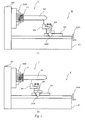
- FIG. 1 is a schematic view of a preform and a cutting device therefor according to an embodiment of the present invention.
- a preform 1 as a prototype of a PET bottle (or a resin bottle) is formed in a closed-end cylindrical shape having an opening at one end and closed at the other end.
- the preform 1 includes a neck portion 11 on the opening side on which a threaded portion for screwing on a cap of the PET bottle is formed, and a body portion 12 as the remaining portion.
- a cutting device 2 is a device for cutting the preform 1.
- the cutting device 2 uses a cutter in place of a cutting tool for a lathe, and is constructed mainly of a foundation 21, a spindle stock 22, and a slider 23.
- the spindle stock 22 includes a chuck 22A which is rotatable around an axis of rotation (or a main spindle), and a motor (unillustrated) for rotating the chuck 22A.
- a central axis of the chuck 22A coincides with the axis of rotation.
- the slider 23 is configured to be capable of advancing and retreating on the foundation 21 along a direction from side to side as seen in FIG. 1 by turning a handle 23A (see Parts (a) and (b) of FIG. 1 ).
- the slider 23 is provided with a tool rest 24.
- the tool rest 24 is configured to be capable of advancing and retreating on the slider 23 along a vertical direction as seen in FIG. 1 by turning a handle 24A.
- the tool rest 24 has a cutter 25 fixed thereto in such a manner that the direction of a blade is orthogonal to the axis of rotation of the spindle stock 22.
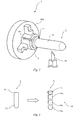
- FIG. 2 is an enlarged perspective view of the chuck 22A.
- the chuck 22A is a chuck with three claws.
- the chuck 22A grips the neck portion 11 of the preform 1 through a cylindrical nylon chuck 3.
- the three claws grip the uneven threaded portion formed on an outer periphery of the neck portion 11, and thus, the neck portion 11 cannot be fixed with stability. Therefore, it is difficult to bring a central axis of the preform 1 into coincidence with the central axis of the chuck 22A. Meanwhile, when the neck portion 11 is gripped through the nylon chuck 3, the neck portion 11 can be gripped with stability since the nylon chuck 3 has not an uneven surface.
- the central axis of the preform 1 can be easily brought into coincidence with the central axis of the chuck 22A, or equivalently, the axis of rotation of the spindle stock 22 (see FIG. 1 ).
- the nylon chuck 3 has a slit 3A formed along a direction of the central axis. This enables increasing and reducing the size of a diameter of the nylon chuck 3, thus facilitating attachment and detachment of the nylon chuck 3 to and from the neck portion 11.
- the body portion 12 of the preform 1 has plural inspection parts preset therein. Then, the body portion 12 is divided into the inspection parts by cutting the preform 1 by using the cutting device 2. Specifically, first, the chuck 22A is caused to grip the neck portion 11 of the preform 1 in such a way as to bring the central axis of the preform 1 into coincidence with the axis of rotation of the spindle stock 22. Then, the handle 23A is turned to advance or retreat the slider 23 and move the blade of the cutter 25 to a predetermined position, or equivalently, a cutting position for each of the inspection parts.
- the motor of the spindle stock 22 is driven to rotate the preform 1 around the axis of rotation.
- the handle 24A is turned to move the tool rest 24 and force the blade of the cutter 25 into the body portion 12 of the preform 1.
- the preform 1 is cut in section for each of the inspection parts along a direction orthogonal to the axis of rotation.
- the preform 1 is cut by cutting off the inspection parts in sequence, starting at the inspection part far away from the neck portion 11.
- FIG. 3 is a view of a state of the preform 1 as cut for each of the inspection parts.
- the body portion 12 of the preform 1 exclusive of the neck portion 11 is divided into three inspection parts 12a to 12c.
- wall thicknesses of the inspection parts 12a to 12c are measured (at a first step).
- a difference between each of the wall thicknesses of the inspection parts 12a to 12c and a set value is inspected for each of the inspection parts by comparing each of the wall thicknesses of the inspection parts 12a to 12c with the preset set value (at a second step).
- the wall thicknesses of the inspection parts 12a to 12c may be estimated by measuring weights of the inspection parts 12a to 12c.
- FIG. 4 is a general schematic view of a blow molding machine.
- a PET bottle 4 is formed by charging the preform 1 into a blow molding machine 5, and executing a blow molding process. Description will be given below with regard to a method for producing the PET bottle 4.
- FIG. 5 is a view of assistance in explaining a process of blow molding.
- the blow molding process includes five processes.
- a temperature is adjusted by heating the preform 1 by a heater 51 for blow molding provided in the blow molding machine 5.
- the heater 51 for blow molding is configured as plural heaters having a shape along an outer periphery of the preform 1, which are arranged along the central axis of the preform 1.
- the heater 51 for blow molding is provided for each of the inspection parts of the preform 1.
- the body portion 12 of the preform 1 is inserted into a mold 52 formed in the same shape as an outer shape of the PET bottle 4.
- a drawing rod 53 is inserted into the preform 1 through the opening of the neck portion 11 to press the preform 1 along the central axis and thereby press-draw the preform 1.
- high-pressure air is introduced into the preform 1 through the opening of the neck portion 11 to expand the preform 1 so as to bring the preform 1 into intimate contact with the inside of the mold 52, thereby molding the PET bottle 4.
- the PET bottle 4 is cooled, and thereafter, the mold 52 is opened to remove the PET bottle 4.
- FIG. 6 is a view of correspondences between the preform and the PET bottle.
- the temperature of the heater 51 for blow molding (or a condition for blow molding) is adjusted in accordance with an inspection result of each of the inspection parts of the preform 1 (at a third step).
- a part having a relatively lower temperature than other parts is less likely to expand, while a part having a relatively higher temperature than other parts is more likely to expand. Therefore, the temperature of an inspection part in which the wall thickness is less than the set value is adjusted relatively lower than that of other inspection parts. Also, the temperature of an inspection part in which the wall thickness is greater than the set value is adjusted relatively higher than that of other inspection parts.
- the temperature of the heater 51 for blow molding for the inspection part 12a is set relatively lower than that for the other inspection parts 12b, 12c. This makes it more difficult for the inspection part 12a to expand in the blow molding process than the other inspection parts 12b, 12c. Therefore, the wall thickness of the inspection part 12a for the PET bottle 4 can be brought close to the set value.
- the wall thicknesses of the plural inspection parts 12a to 12c set in the body portion 12 of the preform 1 are measured, and the difference between each of the measured wall thicknesses and the set value is inspected for each of the inspection parts by comparing each of the measured wall thicknesses with the preset set value. Then, the temperature of the heater 51 for blow molding is adjusted in accordance with the inspection result of each of the inspection parts. Therefore, the temperature of the heater 51 for blow molding can be optimized without repeating the molding of the PET bottle 4, and thus, production efficiency of the PET bottle 4 can be improved.
- the wall thicknesses of the inspection parts 12a to 12c are measured after the preform 1 has been cut by the cutting device 2.
- a device for measuring the shape of the preform, or the like, for example may be used to measure the wall thicknesses of the inspection parts without cutting the preform.
- the weights of the inspection parts rather than the wall thicknesses thereof may be measured.
- the first step may be performed in any manner, provided only that the first step measures the weights or the wall thicknesses of the plural inspection parts set in the body portion of the preform.
- the temperature of the heater 51 for blow molding is adjusted in accordance with the inspection result of each of the inspection parts of the preform 1.
- other conditions may be set as the condition for blow molding to be adjusted in accordance with the inspection result.
- the pressure of the high-pressure air introduced into the preform may be adjusted. In this case, the pressure may be reduced to increase the wall thickness. Meanwhile, the pressure may be increased to reduce the wall thickness.
- the timing of introduction of the high-pressure air into the preform may be adjusted. In this case, the timing may be delayed to reduce the temperature of the preform at the time of the introduction of the high-pressure air and thus increase the wall thickness. Meanwhile, the timing may be advanced to increase the temperature of the preform at the time of the introduction of the high-pressure air and thus reduce the wall thickness.
- the inspection of the preform 1 for each of the inspection parts be made on all preforms 1 to be blow-molded, and the inspection may be made only on some of the preforms charged into the blow molding machine 5.
- the preforms 1 in the same production lot may be sampled for the inspection.
- the PET bottles can be produced by performing blow molding on all preforms 1 to be blow-molded, under the condition for blow molding adjusted in accordance with the inspection results of the one or more preforms 1.
- the present invention is widely applicable to the method for producing the resin bottle formed from the preform as the prototype by the blow molding process.
Landscapes
- Engineering & Computer Science (AREA)
- Manufacturing & Machinery (AREA)
- Mechanical Engineering (AREA)
- Blow-Moulding Or Thermoforming Of Plastics Or The Like (AREA)
Abstract
Description
- The present invention relates to a method for producing a resin bottle formed from a preform as a prototype by a blow molding process.
- Some containers for containing liquid contents such as drinks are made of various materials. A synthetic resin bottle, for example, a bottle blow-molded of polyethylene terephthalate (or a PET bottle), is known as a type of container as described above.
Patent Literature 1 discloses a method for forming a PET bottle from a preform as a prototype by a blow molding process. Specifically, a closed-end cylindrical preform having an opening at one end and closed at the other end is heated, and a body portion of the preform is inserted into a mold formed in the same shape as an outer shape of the PET bottle, with a neck portion of the preform on the opening side thereof gripped. Then, high-pressure air is introduced into the preform through its opening to expand the preform so as to bring the preform into intimate contact with the inside of the mold, thereby forming the PET bottle. The PET bottle, when undergoing quality inspection, is divided into plural cutoff pieces by being cut in section for each of inspection parts. -
FIG. 7 is a view of a state of a PET bottle as cut for each of inspection parts. In an example ofFIG. 7 , aPET bottle 10 is divided into fourcutoff pieces 10a to 10d. The quality inspection involves measuring thecutoff pieces 10a to 10d for weight, wall thickness, buckling strength or the like, and comparing measured results with a preset set value, thereby inspecting the PET bottle for quality. When there is a great difference between the measured results and the set value, the results of the quality inspection are fed back into the blow molding process to adjust a condition for blow molding, such as the temperature of the preform. This improves the yield rate of the PET bottle. For example, a part in which the wall thickness is less than the set value can be considered to be a thin-walled part of the preform as compared to other parts. This can be considered to be due to the fact that the thin-walled part of the preform is prone to conduct heat and thus, in the blow molding process, the thin-walled part rises high in its temperature relatively to other parts and hence expands larger than other parts by the introduction of the high-pressure air. Therefore, setting the temperature of the thin-walled part low enables the wall thickness to approach the set value. - Patent Literature 1: Japanese Patent Application Publication No.
Hei 11-179794 - With such quality inspection, however, the condition for blow molding, such as the temperature of the preform, can be adjusted only after the blow molding process, and thus, the PET bottle is molded once with the condition for blow molding improperly adjusted. Therefore, optimization of the condition for blow molding requires repeating the molding of the PET bottle, which in turn leads to the problem of reducing production efficiency of the PET bottle.
- An object of the present invention is to improve production efficiency of resin bottles by optimizing a condition for blow molding without repeating molding of the resin bottles.
- In order to solve the foregoing problem, the present invention provides a method for producing a resin bottle formed from a preform as a prototype by a blow molding process, including a first step, a second step, and a third step. The first step measures each of weights or wall thicknesses of plural inspection parts set in a body portion of the preform. The second step compares each of the weights or the wall thicknesses measured by the first step with a preset set value, and thereby inspects a difference between each of the weights or the wall thicknesses measured by the first step and the set value for each of the inspection parts. The third step adjusts a condition for blow molding in the blow molding process in accordance with an inspection result of each of the inspection parts.
- Here, in the present invention, it is preferable that, the third step comprises adjusting the condition for blow molding in the blow molding process by adjusting a temperature for each of the inspection parts. Also, it is preferable that, the third step comprises adjusting the condition for blow molding in the blow molding process by adjusting a pressure of air introduced into the preform. Also, it is preferable that, the third step comprises adjusting the condition for blow molding in the blow molding process by adjusting the timing of introduction of the air into the preform. Further, it is preferable that the first step comprises measuring the weight or the wall thickness for each of the inspection parts after the body portion of the preform has been cut for each of the inspection parts.
- According to the present invention, the weights or the wall thicknesses of the plural inspection parts set in the body portion of the preform are measured, and the difference between each of the measured weights or wall thicknesses and the set value is inspected for each of the inspection parts by comparing each of the measured weights or wall thicknesses with the preset set value. Then, the condition for blow molding in the blow molding process is adjusted in accordance with the inspection result of each of the inspection parts. Therefore, the condition for blow molding can be optimized without repeating the molding of the resin bottles, or equivalently, without undergoing the blow molding process, and thus, the production efficiency of the resin bottles can be improved.
-
-
FIG. 1 is a schematic view of a preform and a cutting device therefor according to an embodiment of the present invention. -
FIG. 2 is an enlarged perspective view of a chuck according to the embodiment. -
FIG. 3 is a view of a state of the preform according to the embodiment as cut for each of inspection parts. -
FIG. 4 is a general schematic view of a blow molding machine according to the embodiment. -
FIG. 5 is a view of assistance in explaining a process of blow molding according to the embodiment. -
FIG. 6 is a view of correspondences between the preform and a PET bottle according to the embodiment. -
FIG. 7 is a view of a state of the PET bottle as cut for each of the inspection parts. -
FIG. 1 is a schematic view of a preform and a cutting device therefor according to an embodiment of the present invention. Apreform 1 as a prototype of a PET bottle (or a resin bottle) is formed in a closed-end cylindrical shape having an opening at one end and closed at the other end. Thepreform 1 includes aneck portion 11 on the opening side on which a threaded portion for screwing on a cap of the PET bottle is formed, and abody portion 12 as the remaining portion. - A
cutting device 2 is a device for cutting thepreform 1. Thecutting device 2 uses a cutter in place of a cutting tool for a lathe, and is constructed mainly of afoundation 21, aspindle stock 22, and aslider 23. Thespindle stock 22 includes achuck 22A which is rotatable around an axis of rotation (or a main spindle), and a motor (unillustrated) for rotating thechuck 22A. A central axis of thechuck 22A coincides with the axis of rotation. Theslider 23 is configured to be capable of advancing and retreating on thefoundation 21 along a direction from side to side as seen inFIG. 1 by turning ahandle 23A (see Parts (a) and (b) ofFIG. 1 ). Theslider 23 is provided with atool rest 24. Thetool rest 24 is configured to be capable of advancing and retreating on theslider 23 along a vertical direction as seen inFIG. 1 by turning ahandle 24A. Also, thetool rest 24 has acutter 25 fixed thereto in such a manner that the direction of a blade is orthogonal to the axis of rotation of thespindle stock 22. -
FIG. 2 is an enlarged perspective view of thechuck 22A. Thechuck 22A is a chuck with three claws. Thechuck 22A grips theneck portion 11 of thepreform 1 through acylindrical nylon chuck 3. When thechuck 22A directly grips theneck portion 11, the three claws grip the uneven threaded portion formed on an outer periphery of theneck portion 11, and thus, theneck portion 11 cannot be fixed with stability. Therefore, it is difficult to bring a central axis of thepreform 1 into coincidence with the central axis of thechuck 22A. Meanwhile, when theneck portion 11 is gripped through thenylon chuck 3, theneck portion 11 can be gripped with stability since thenylon chuck 3 has not an uneven surface. Therefore, the central axis of thepreform 1 can be easily brought into coincidence with the central axis of thechuck 22A, or equivalently, the axis of rotation of the spindle stock 22 (seeFIG. 1 ). Also, thenylon chuck 3 has aslit 3A formed along a direction of the central axis. This enables increasing and reducing the size of a diameter of thenylon chuck 3, thus facilitating attachment and detachment of thenylon chuck 3 to and from theneck portion 11. - Next, description will be given with regard to a method for inspecting the
preform 1. Thebody portion 12 of thepreform 1 has plural inspection parts preset therein. Then, thebody portion 12 is divided into the inspection parts by cutting thepreform 1 by using thecutting device 2. Specifically, first, thechuck 22A is caused to grip theneck portion 11 of thepreform 1 in such a way as to bring the central axis of thepreform 1 into coincidence with the axis of rotation of thespindle stock 22. Then, thehandle 23A is turned to advance or retreat theslider 23 and move the blade of thecutter 25 to a predetermined position, or equivalently, a cutting position for each of the inspection parts. Then, the motor of thespindle stock 22 is driven to rotate thepreform 1 around the axis of rotation. Then, thehandle 24A is turned to move thetool rest 24 and force the blade of thecutter 25 into thebody portion 12 of thepreform 1. Thereby, thepreform 1 is cut in section for each of the inspection parts along a direction orthogonal to the axis of rotation. At the time of this cutting, thepreform 1 is cut by cutting off the inspection parts in sequence, starting at the inspection part far away from theneck portion 11. -
FIG. 3 is a view of a state of thepreform 1 as cut for each of the inspection parts. In an example ofFIG. 3 , thebody portion 12 of thepreform 1 exclusive of theneck portion 11 is divided into threeinspection parts 12a to 12c. In quality inspection of thepreform 1, after thebody portion 12 has been cut for each of the inspection parts, wall thicknesses of theinspection parts 12a to 12c are measured (at a first step). Then, a difference between each of the wall thicknesses of theinspection parts 12a to 12c and a set value is inspected for each of the inspection parts by comparing each of the wall thicknesses of theinspection parts 12a to 12c with the preset set value (at a second step). Incidentally, the wall thicknesses of theinspection parts 12a to 12c may be estimated by measuring weights of theinspection parts 12a to 12c. -
FIG. 4 is a general schematic view of a blow molding machine. APET bottle 4 is formed by charging thepreform 1 into ablow molding machine 5, and executing a blow molding process. Description will be given below with regard to a method for producing thePET bottle 4. -
FIG. 5 is a view of assistance in explaining a process of blow molding. The blow molding process includes five processes. In a first process, a temperature is adjusted by heating thepreform 1 by aheater 51 for blow molding provided in theblow molding machine 5. Theheater 51 for blow molding is configured as plural heaters having a shape along an outer periphery of thepreform 1, which are arranged along the central axis of thepreform 1. In other words, theheater 51 for blow molding is provided for each of the inspection parts of thepreform 1. In a second process, thebody portion 12 of thepreform 1 is inserted into amold 52 formed in the same shape as an outer shape of thePET bottle 4. In a third process, a drawingrod 53 is inserted into thepreform 1 through the opening of theneck portion 11 to press thepreform 1 along the central axis and thereby press-draw thepreform 1. In a fourth process, high-pressure air is introduced into thepreform 1 through the opening of theneck portion 11 to expand thepreform 1 so as to bring thepreform 1 into intimate contact with the inside of themold 52, thereby molding thePET bottle 4. In a fifth process, thePET bottle 4 is cooled, and thereafter, themold 52 is opened to remove thePET bottle 4. -
FIG. 6 is a view of correspondences between the preform and the PET bottle. In the second process, the temperature of theheater 51 for blow molding (or a condition for blow molding) is adjusted in accordance with an inspection result of each of the inspection parts of the preform 1 (at a third step). Here, in the blow molding process, a part having a relatively lower temperature than other parts is less likely to expand, while a part having a relatively higher temperature than other parts is more likely to expand. Therefore, the temperature of an inspection part in which the wall thickness is less than the set value is adjusted relatively lower than that of other inspection parts. Also, the temperature of an inspection part in which the wall thickness is greater than the set value is adjusted relatively higher than that of other inspection parts. For example, when the wall thickness of theinspection part 12a is less than the set value, the temperature of theheater 51 for blow molding for theinspection part 12a is set relatively lower than that for theother inspection parts inspection part 12a to expand in the blow molding process than theother inspection parts inspection part 12a for thePET bottle 4 can be brought close to the set value. - According to the embodiment, as described above, the wall thicknesses of the
plural inspection parts 12a to 12c set in thebody portion 12 of thepreform 1 are measured, and the difference between each of the measured wall thicknesses and the set value is inspected for each of the inspection parts by comparing each of the measured wall thicknesses with the preset set value. Then, the temperature of theheater 51 for blow molding is adjusted in accordance with the inspection result of each of the inspection parts. Therefore, the temperature of theheater 51 for blow molding can be optimized without repeating the molding of thePET bottle 4, and thus, production efficiency of thePET bottle 4 can be improved. - Incidentally, in the above-mentioned embodiment, the wall thicknesses of the
inspection parts 12a to 12c are measured after thepreform 1 has been cut by thecutting device 2. However, a device for measuring the shape of the preform, or the like, for example, may be used to measure the wall thicknesses of the inspection parts without cutting the preform. Also, the weights of the inspection parts rather than the wall thicknesses thereof may be measured. In short, the first step may be performed in any manner, provided only that the first step measures the weights or the wall thicknesses of the plural inspection parts set in the body portion of the preform. - Also, in the above-mentioned embodiment, the temperature of the
heater 51 for blow molding is adjusted in accordance with the inspection result of each of the inspection parts of thepreform 1. However, other conditions may be set as the condition for blow molding to be adjusted in accordance with the inspection result. For example, the pressure of the high-pressure air introduced into the preform may be adjusted. In this case, the pressure may be reduced to increase the wall thickness. Meanwhile, the pressure may be increased to reduce the wall thickness. Also, the timing of introduction of the high-pressure air into the preform, for example, may be adjusted. In this case, the timing may be delayed to reduce the temperature of the preform at the time of the introduction of the high-pressure air and thus increase the wall thickness. Meanwhile, the timing may be advanced to increase the temperature of the preform at the time of the introduction of the high-pressure air and thus reduce the wall thickness. - Further, in the above-mentioned embodiment, it is not necessary that the inspection of the
preform 1 for each of the inspection parts be made on allpreforms 1 to be blow-molded, and the inspection may be made only on some of the preforms charged into theblow molding machine 5. For example, one or more of thepreforms 1 in the same production lot may be sampled for the inspection. In this case, the PET bottles can be produced by performing blow molding on allpreforms 1 to be blow-molded, under the condition for blow molding adjusted in accordance with the inspection results of the one ormore preforms 1. - As described above, the present invention is widely applicable to the method for producing the resin bottle formed from the preform as the prototype by the blow molding process.
-
- 1
- preform
- 2
- cutting device
- 3
- nylon chuck
- 3A
- slit
- 4
- PET bottle (resin bottle)
- 5
- blow molding machine
- 11
- neck portion
- 12
- body portion
- 12a-12c
- inspection parts
- 21
- foundation
- 22
- spindle stock
- 22A
- chuck
- 23
- slider
- 23A
- handle
- 24
- tool rest
- 24A
- handle
- 25
- cutter
- 51
- heater for blow molding
- 52
- mold
- 53
- drawing rod
Claims (5)
- A method for producing a resin bottle formed from a preform as a prototype by a blow molding process, comprising:a first step of measuring each of weights or wall thicknesses of a plurality of inspection parts set in a body portion of the preform;a second step of comparing each of the weights or the wall thicknesses measured by the first step with a preset set value, and thereby inspecting a difference between each of the weights or the wall thicknesses measured by the first step and the set value for each of the inspection parts; anda third step of adjusting a condition for blow molding in the blow molding process in accordance with an inspection result of each of the inspection parts.
- The method for producing a resin bottle according to claim 1, wherein the third step comprises adjusting the condition for blow molding in the blow molding process by adjusting a temperature for each of the inspection parts.
- The method for producing a resin bottle according to claim 1, wherein the third step comprises adjusting the condition for blow molding in the blow molding process by adjusting a pressure of air introduced into the preform.
- The method for producing a resin bottle according to claim 1, wherein the third step comprises adjusting the condition for blow molding in the blow molding process by adjusting the timing of introduction of the air into the preform.
- The method for producing a resin bottle according to any one of claims 1 to 4, wherein the first step comprises measuring the weight or the wall thickness for each of the inspection parts after the body portion of the preform has been cut for each of the inspection parts.
Applications Claiming Priority (2)
| Application Number | Priority Date | Filing Date | Title |
|---|---|---|---|
| JP2011116864A JP5335028B2 (en) | 2011-05-25 | 2011-05-25 | Plastic bottle manufacturing method |
| PCT/JP2012/062989 WO2012161171A1 (en) | 2011-05-25 | 2012-05-22 | Method for producing resin bottles |
Publications (3)
| Publication Number | Publication Date |
|---|---|
| EP2716431A1 true EP2716431A1 (en) | 2014-04-09 |
| EP2716431A4 EP2716431A4 (en) | 2015-09-23 |
| EP2716431B1 EP2716431B1 (en) | 2016-12-07 |
Family
ID=47194320
Family Applications (1)
| Application Number | Title | Priority Date | Filing Date |
|---|---|---|---|
| EP12789773.4A Not-in-force EP2716431B1 (en) | 2011-05-25 | 2012-05-22 | Method for producing resin bottles |
Country Status (8)
| Country | Link |
|---|---|
| US (1) | US9555576B2 (en) |
| EP (1) | EP2716431B1 (en) |
| JP (1) | JP5335028B2 (en) |
| CN (1) | CN102794903A (en) |
| ES (1) | ES2608154T3 (en) |
| SG (1) | SG195074A1 (en) |
| TW (1) | TWI503220B (en) |
| WO (1) | WO2012161171A1 (en) |
Families Citing this family (7)
| Publication number | Priority date | Publication date | Assignee | Title |
|---|---|---|---|---|
| CN106626325B (en) * | 2016-11-30 | 2019-05-03 | 蔡怀峰 | Processing method of oblique mouth packaging tube |
| KR102002149B1 (en) * | 2017-04-26 | 2019-07-24 | 에이테크솔루션(주) | Method of manufacturing optical mirror for head-up display |
| JP7539349B2 (en) * | 2021-06-07 | 2024-08-23 | サントリーホールディングス株式会社 | Blow molding machine and method for determining product defects |
| DE102021128918A1 (en) * | 2021-11-05 | 2023-05-11 | Krones Aktiengesellschaft | Device and method for manufacturing plastic containers with inspection |
| FR3131557B1 (en) * | 2021-12-30 | 2024-06-21 | Sidel Participations | Process for manufacturing containers and installation for its implementation |
| DE102022111523A1 (en) * | 2022-05-09 | 2023-11-09 | Krones Aktiengesellschaft | Method and device for producing plastic containers with zone-by-zone inspection of plastic preforms |
| CN115401900A (en) * | 2022-08-25 | 2022-11-29 | 张家港市绿环机械有限公司 | Thickness measuring and temperature regulating system and thickness measuring and temperature regulating process of injection stretch blow molding machine |
Family Cites Families (20)
| Publication number | Priority date | Publication date | Assignee | Title |
|---|---|---|---|---|
| US3950459A (en) * | 1972-12-27 | 1976-04-13 | Phillips Petroleum Company | Continuous process for producing, reheating, and blow molding parisons |
| JPS6230020A (en) | 1985-08-01 | 1987-02-09 | Ishikawajima Harima Heavy Ind Co Ltd | Plastic blow molding process |
| DE3816273C3 (en) * | 1988-05-12 | 1996-03-21 | Harald Feuerherm | Process for extrusion blow molding of a hollow body and device for carrying out the process |
| JPH0464411A (en) | 1990-07-04 | 1992-02-28 | Ishikawajima Harima Heavy Ind Co Ltd | Controlling method for parison-shape |
| JPH0813498B2 (en) * | 1992-02-29 | 1996-02-14 | 日精エー・エス・ビー機械株式会社 | Molding method for heat-resistant container |
| JP3233980B2 (en) * | 1992-04-27 | 2001-12-04 | 本田技研工業株式会社 | Blow molding molding control system and molding control method |
| DE19544634A1 (en) | 1995-11-30 | 1997-06-05 | Feuerherm Harald | Process for blow molding hollow bodies made of thermoplastic |
| JP3799788B2 (en) | 1997-12-25 | 2006-07-19 | 凸版印刷株式会社 | Molding method of plastic bottle |
| DE19813668C2 (en) | 1998-03-27 | 2003-04-30 | Ossberger Gmbh & Co | Manufacturing device with control devices for a hollow plastic body |
| MXPA02008466A (en) | 2000-03-01 | 2002-12-13 | Plastic Techn Inc | METHOD AND APPARATUS FOR MEASURING THE WALL THICKNESS OF A PLASTIC CONTAINER. |
| EP1719970A3 (en) | 2000-03-01 | 2009-11-18 | Plastic Technologies, Inc. | Method and apparatus for measuring wall thickness of a plastic container |
| CN1455729A (en) | 2001-02-06 | 2003-11-12 | 花王株式会社 | Method and device for design of preform |
| JP3597508B2 (en) * | 2001-02-06 | 2004-12-08 | 花王株式会社 | Preform design method and apparatus |
| JP2003062896A (en) * | 2001-08-24 | 2003-03-05 | Lion Corp | Container thickness design system and container thickness design method |
| US20060058911A1 (en) * | 2004-09-13 | 2006-03-16 | Graham Packaging Company, L.P. | System and method for phase monitoring during blow molding |
| CN101249721B (en) | 2008-03-13 | 2010-09-08 | 华南理工大学 | An online control system and method for wall thickness of extrusion blow molded products based on image recognition technology |
| DE102008052611B3 (en) | 2008-10-21 | 2010-04-08 | Feuerherm, Harald, Dipl.-Ing. | Process for producing plastic hollow bodies by blow molding |
| DE102008057999A1 (en) * | 2008-11-13 | 2010-05-20 | Khs Corpoplast Gmbh & Co. Kg | Method and apparatus for blow molding containers |
| DE102009035868A1 (en) * | 2009-07-31 | 2011-02-03 | Krones Ag | Device for forming plastic preforms with synchronous heating and stretching |
| JP5738070B2 (en) | 2011-05-25 | 2015-06-17 | サントリーホールディングス株式会社 | Preform cutting device |
-
2011
- 2011-05-25 JP JP2011116864A patent/JP5335028B2/en active Active
-
2012
- 2012-05-22 EP EP12789773.4A patent/EP2716431B1/en not_active Not-in-force
- 2012-05-22 ES ES12789773.4T patent/ES2608154T3/en active Active
- 2012-05-22 TW TW101118182A patent/TWI503220B/en not_active IP Right Cessation
- 2012-05-22 SG SG2013086004A patent/SG195074A1/en unknown
- 2012-05-22 WO PCT/JP2012/062989 patent/WO2012161171A1/en not_active Ceased
- 2012-05-22 US US14/112,560 patent/US9555576B2/en active Active
- 2012-05-23 CN CN2012101638129A patent/CN102794903A/en active Pending
Also Published As
| Publication number | Publication date |
|---|---|
| TW201313446A (en) | 2013-04-01 |
| NZ616760A (en) | 2014-09-26 |
| US9555576B2 (en) | 2017-01-31 |
| WO2012161171A1 (en) | 2012-11-29 |
| US20140077404A1 (en) | 2014-03-20 |
| ES2608154T3 (en) | 2017-04-06 |
| EP2716431B1 (en) | 2016-12-07 |
| SG195074A1 (en) | 2013-12-30 |
| JP5335028B2 (en) | 2013-11-06 |
| CN102794903A (en) | 2012-11-28 |
| EP2716431A4 (en) | 2015-09-23 |
| JP2012245636A (en) | 2012-12-13 |
| TWI503220B (en) | 2015-10-11 |
Similar Documents
| Publication | Publication Date | Title |
|---|---|---|
| US9555576B2 (en) | Method for producing resin bottles | |
| CN107530948B (en) | Injection molding die of injection stretch blow molding machine, method for forming preform, preform, and method for forming container and container | |
| RU2627858C2 (en) | Method and device for optimized bottom contour manufacture on workpiece | |
| EP2463079A1 (en) | A process for single-step forming and filling of containers | |
| US9586713B2 (en) | Preform for producing plastic containers in a stretch-blow-moulding process | |
| JP6712259B2 (en) | Control method of blow molding method for container made of plastic material | |
| US10683126B2 (en) | Etched preform tip | |
| EP3159137B1 (en) | Manufacturing method and manufacturing apparatus for hollow container | |
| US9962881B2 (en) | Tooling and process for injection stretch blow molded container with integral handle | |
| AU2011302329B2 (en) | Hydroblow preform design | |
| US5054267A (en) | Apparatus sealing blow molded bottle | |
| CN112340213A (en) | Screw caps and food packaging containers | |
| JP2017020651A (en) | Process of manufacture of proof pressure container, preforming body used at process of manufacture and container | |
| JP5738070B2 (en) | Preform cutting device | |
| NZ616760B2 (en) | Method for producing resin bottles | |
| EP2633977A1 (en) | Production method for hollow container | |
| KR102394752B1 (en) | Method and apparatus for the production of an optimized neck contour on preforms | |
| US9902103B2 (en) | Injection stretch blow molding method and apparatus for producing internally threaded containers | |
| JP2011116082A (en) | Method for manufacturing container made of synthetic resin, preform, insert member, and container made of synthetic resin | |
| US10543634B2 (en) | Method for automatic adjustment of the travel of a stretching rod of a device for forming hollow bodies | |
| US10703037B2 (en) | Injection stretch blow molding method and apparatus for producing internally threaded containers | |
| GB2474028A (en) | Blow moulding of preforms |
Legal Events
| Date | Code | Title | Description |
|---|---|---|---|
| PUAI | Public reference made under article 153(3) epc to a published international application that has entered the european phase |
Free format text: ORIGINAL CODE: 0009012 |
|
| 17P | Request for examination filed |
Effective date: 20131204 |
|
| AK | Designated contracting states |
Kind code of ref document: A1 Designated state(s): AL AT BE BG CH CY CZ DE DK EE ES FI FR GB GR HR HU IE IS IT LI LT LU LV MC MK MT NL NO PL PT RO RS SE SI SK SM TR |
|
| DAX | Request for extension of the european patent (deleted) | ||
| RA4 | Supplementary search report drawn up and despatched (corrected) |
Effective date: 20150821 |
|
| RIC1 | Information provided on ipc code assigned before grant |
Ipc: B29C 49/78 20060101AFI20150817BHEP Ipc: B29C 49/06 20060101ALN20150817BHEP |
|
| GRAP | Despatch of communication of intention to grant a patent |
Free format text: ORIGINAL CODE: EPIDOSNIGR1 |
|
| INTG | Intention to grant announced |
Effective date: 20160707 |
|
| RIC1 | Information provided on ipc code assigned before grant |
Ipc: B29C 49/78 20060101AFI20160624BHEP Ipc: B29C 49/06 20060101ALN20160624BHEP |
|
| GRAS | Grant fee paid |
Free format text: ORIGINAL CODE: EPIDOSNIGR3 |
|
| GRAA | (expected) grant |
Free format text: ORIGINAL CODE: 0009210 |
|
| AK | Designated contracting states |
Kind code of ref document: B1 Designated state(s): AL AT BE BG CH CY CZ DE DK EE ES FI FR GB GR HR HU IE IS IT LI LT LU LV MC MK MT NL NO PL PT RO RS SE SI SK SM TR |
|
| REG | Reference to a national code |
Ref country code: GB Ref legal event code: FG4D |
|
| REG | Reference to a national code |
Ref country code: CH Ref legal event code: EP Ref country code: AT Ref legal event code: REF Ref document number: 851330 Country of ref document: AT Kind code of ref document: T Effective date: 20161215 |
|
| REG | Reference to a national code |
Ref country code: IE Ref legal event code: FG4D |
|
| REG | Reference to a national code |
Ref country code: DE Ref legal event code: R096 Ref document number: 602012026360 Country of ref document: DE |
|
| PG25 | Lapsed in a contracting state [announced via postgrant information from national office to epo] |
Ref country code: LV Free format text: LAPSE BECAUSE OF FAILURE TO SUBMIT A TRANSLATION OF THE DESCRIPTION OR TO PAY THE FEE WITHIN THE PRESCRIBED TIME-LIMIT Effective date: 20161207 |
|
| REG | Reference to a national code |
Ref country code: ES Ref legal event code: FG2A Ref document number: 2608154 Country of ref document: ES Kind code of ref document: T3 Effective date: 20170406 |
|
| REG | Reference to a national code |
Ref country code: LT Ref legal event code: MG4D |
|
| REG | Reference to a national code |
Ref country code: NL Ref legal event code: MP Effective date: 20161207 |
|
| PG25 | Lapsed in a contracting state [announced via postgrant information from national office to epo] |
Ref country code: NO Free format text: LAPSE BECAUSE OF FAILURE TO SUBMIT A TRANSLATION OF THE DESCRIPTION OR TO PAY THE FEE WITHIN THE PRESCRIBED TIME-LIMIT Effective date: 20170307 Ref country code: SE Free format text: LAPSE BECAUSE OF FAILURE TO SUBMIT A TRANSLATION OF THE DESCRIPTION OR TO PAY THE FEE WITHIN THE PRESCRIBED TIME-LIMIT Effective date: 20161207 Ref country code: LT Free format text: LAPSE BECAUSE OF FAILURE TO SUBMIT A TRANSLATION OF THE DESCRIPTION OR TO PAY THE FEE WITHIN THE PRESCRIBED TIME-LIMIT Effective date: 20161207 Ref country code: GR Free format text: LAPSE BECAUSE OF FAILURE TO SUBMIT A TRANSLATION OF THE DESCRIPTION OR TO PAY THE FEE WITHIN THE PRESCRIBED TIME-LIMIT Effective date: 20170308 |
|
| REG | Reference to a national code |
Ref country code: AT Ref legal event code: MK05 Ref document number: 851330 Country of ref document: AT Kind code of ref document: T Effective date: 20161207 |
|
| REG | Reference to a national code |
Ref country code: FR Ref legal event code: PLFP Year of fee payment: 6 |
|
| PG25 | Lapsed in a contracting state [announced via postgrant information from national office to epo] |
Ref country code: FI Free format text: LAPSE BECAUSE OF FAILURE TO SUBMIT A TRANSLATION OF THE DESCRIPTION OR TO PAY THE FEE WITHIN THE PRESCRIBED TIME-LIMIT Effective date: 20161207 Ref country code: HR Free format text: LAPSE BECAUSE OF FAILURE TO SUBMIT A TRANSLATION OF THE DESCRIPTION OR TO PAY THE FEE WITHIN THE PRESCRIBED TIME-LIMIT Effective date: 20161207 Ref country code: RS Free format text: LAPSE BECAUSE OF FAILURE TO SUBMIT A TRANSLATION OF THE DESCRIPTION OR TO PAY THE FEE WITHIN THE PRESCRIBED TIME-LIMIT Effective date: 20161207 |
|
| PG25 | Lapsed in a contracting state [announced via postgrant information from national office to epo] |
Ref country code: NL Free format text: LAPSE BECAUSE OF FAILURE TO SUBMIT A TRANSLATION OF THE DESCRIPTION OR TO PAY THE FEE WITHIN THE PRESCRIBED TIME-LIMIT Effective date: 20161207 |
|
| PG25 | Lapsed in a contracting state [announced via postgrant information from national office to epo] |
Ref country code: RO Free format text: LAPSE BECAUSE OF FAILURE TO SUBMIT A TRANSLATION OF THE DESCRIPTION OR TO PAY THE FEE WITHIN THE PRESCRIBED TIME-LIMIT Effective date: 20161207 Ref country code: IS Free format text: LAPSE BECAUSE OF FAILURE TO SUBMIT A TRANSLATION OF THE DESCRIPTION OR TO PAY THE FEE WITHIN THE PRESCRIBED TIME-LIMIT Effective date: 20170407 Ref country code: CZ Free format text: LAPSE BECAUSE OF FAILURE TO SUBMIT A TRANSLATION OF THE DESCRIPTION OR TO PAY THE FEE WITHIN THE PRESCRIBED TIME-LIMIT Effective date: 20161207 Ref country code: SK Free format text: LAPSE BECAUSE OF FAILURE TO SUBMIT A TRANSLATION OF THE DESCRIPTION OR TO PAY THE FEE WITHIN THE PRESCRIBED TIME-LIMIT Effective date: 20161207 Ref country code: EE Free format text: LAPSE BECAUSE OF FAILURE TO SUBMIT A TRANSLATION OF THE DESCRIPTION OR TO PAY THE FEE WITHIN THE PRESCRIBED TIME-LIMIT Effective date: 20161207 |
|
| PG25 | Lapsed in a contracting state [announced via postgrant information from national office to epo] |
Ref country code: BG Free format text: LAPSE BECAUSE OF FAILURE TO SUBMIT A TRANSLATION OF THE DESCRIPTION OR TO PAY THE FEE WITHIN THE PRESCRIBED TIME-LIMIT Effective date: 20170307 Ref country code: PT Free format text: LAPSE BECAUSE OF FAILURE TO SUBMIT A TRANSLATION OF THE DESCRIPTION OR TO PAY THE FEE WITHIN THE PRESCRIBED TIME-LIMIT Effective date: 20170407 Ref country code: LU Free format text: LAPSE BECAUSE OF NON-PAYMENT OF DUE FEES Effective date: 20170531 Ref country code: AT Free format text: LAPSE BECAUSE OF FAILURE TO SUBMIT A TRANSLATION OF THE DESCRIPTION OR TO PAY THE FEE WITHIN THE PRESCRIBED TIME-LIMIT Effective date: 20161207 Ref country code: SM Free format text: LAPSE BECAUSE OF FAILURE TO SUBMIT A TRANSLATION OF THE DESCRIPTION OR TO PAY THE FEE WITHIN THE PRESCRIBED TIME-LIMIT Effective date: 20161207 Ref country code: BE Free format text: LAPSE BECAUSE OF FAILURE TO SUBMIT A TRANSLATION OF THE DESCRIPTION OR TO PAY THE FEE WITHIN THE PRESCRIBED TIME-LIMIT Effective date: 20161207 Ref country code: PL Free format text: LAPSE BECAUSE OF FAILURE TO SUBMIT A TRANSLATION OF THE DESCRIPTION OR TO PAY THE FEE WITHIN THE PRESCRIBED TIME-LIMIT Effective date: 20161207 |
|
| REG | Reference to a national code |
Ref country code: DE Ref legal event code: R097 Ref document number: 602012026360 Country of ref document: DE |
|
| PLBE | No opposition filed within time limit |
Free format text: ORIGINAL CODE: 0009261 |
|
| STAA | Information on the status of an ep patent application or granted ep patent |
Free format text: STATUS: NO OPPOSITION FILED WITHIN TIME LIMIT |
|
| 26N | No opposition filed |
Effective date: 20170908 |
|
| PG25 | Lapsed in a contracting state [announced via postgrant information from national office to epo] |
Ref country code: SI Free format text: LAPSE BECAUSE OF FAILURE TO SUBMIT A TRANSLATION OF THE DESCRIPTION OR TO PAY THE FEE WITHIN THE PRESCRIBED TIME-LIMIT Effective date: 20161207 Ref country code: DK Free format text: LAPSE BECAUSE OF FAILURE TO SUBMIT A TRANSLATION OF THE DESCRIPTION OR TO PAY THE FEE WITHIN THE PRESCRIBED TIME-LIMIT Effective date: 20161207 |
|
| REG | Reference to a national code |
Ref country code: CH Ref legal event code: PL |
|
| PG25 | Lapsed in a contracting state [announced via postgrant information from national office to epo] |
Ref country code: MC Free format text: LAPSE BECAUSE OF FAILURE TO SUBMIT A TRANSLATION OF THE DESCRIPTION OR TO PAY THE FEE WITHIN THE PRESCRIBED TIME-LIMIT Effective date: 20161207 |
|
| REG | Reference to a national code |
Ref country code: IE Ref legal event code: MM4A |
|
| PG25 | Lapsed in a contracting state [announced via postgrant information from national office to epo] |
Ref country code: LI Free format text: LAPSE BECAUSE OF NON-PAYMENT OF DUE FEES Effective date: 20170531 Ref country code: CH Free format text: LAPSE BECAUSE OF NON-PAYMENT OF DUE FEES Effective date: 20170531 |
|
| PG25 | Lapsed in a contracting state [announced via postgrant information from national office to epo] |
Ref country code: LU Free format text: LAPSE BECAUSE OF NON-PAYMENT OF DUE FEES Effective date: 20170522 |
|
| REG | Reference to a national code |
Ref country code: FR Ref legal event code: PLFP Year of fee payment: 7 |
|
| PG25 | Lapsed in a contracting state [announced via postgrant information from national office to epo] |
Ref country code: IE Free format text: LAPSE BECAUSE OF NON-PAYMENT OF DUE FEES Effective date: 20170522 |
|
| PG25 | Lapsed in a contracting state [announced via postgrant information from national office to epo] |
Ref country code: MT Free format text: LAPSE BECAUSE OF NON-PAYMENT OF DUE FEES Effective date: 20170522 |
|
| PG25 | Lapsed in a contracting state [announced via postgrant information from national office to epo] |
Ref country code: HU Free format text: LAPSE BECAUSE OF FAILURE TO SUBMIT A TRANSLATION OF THE DESCRIPTION OR TO PAY THE FEE WITHIN THE PRESCRIBED TIME-LIMIT; INVALID AB INITIO Effective date: 20120522 |
|
| PG25 | Lapsed in a contracting state [announced via postgrant information from national office to epo] |
Ref country code: CY Free format text: LAPSE BECAUSE OF NON-PAYMENT OF DUE FEES Effective date: 20161207 |
|
| PG25 | Lapsed in a contracting state [announced via postgrant information from national office to epo] |
Ref country code: MK Free format text: LAPSE BECAUSE OF FAILURE TO SUBMIT A TRANSLATION OF THE DESCRIPTION OR TO PAY THE FEE WITHIN THE PRESCRIBED TIME-LIMIT Effective date: 20161207 |
|
| PG25 | Lapsed in a contracting state [announced via postgrant information from national office to epo] |
Ref country code: TR Free format text: LAPSE BECAUSE OF FAILURE TO SUBMIT A TRANSLATION OF THE DESCRIPTION OR TO PAY THE FEE WITHIN THE PRESCRIBED TIME-LIMIT Effective date: 20161207 |
|
| PG25 | Lapsed in a contracting state [announced via postgrant information from national office to epo] |
Ref country code: AL Free format text: LAPSE BECAUSE OF FAILURE TO SUBMIT A TRANSLATION OF THE DESCRIPTION OR TO PAY THE FEE WITHIN THE PRESCRIBED TIME-LIMIT Effective date: 20161207 |
|
| PGFP | Annual fee paid to national office [announced via postgrant information from national office to epo] |
Ref country code: FR Payment date: 20210412 Year of fee payment: 10 |
|
| PGFP | Annual fee paid to national office [announced via postgrant information from national office to epo] |
Ref country code: ES Payment date: 20210601 Year of fee payment: 10 Ref country code: GB Payment date: 20210429 Year of fee payment: 10 |
|
| GBPC | Gb: european patent ceased through non-payment of renewal fee |
Effective date: 20220522 |
|
| PG25 | Lapsed in a contracting state [announced via postgrant information from national office to epo] |
Ref country code: FR Free format text: LAPSE BECAUSE OF NON-PAYMENT OF DUE FEES Effective date: 20220531 |
|
| PG25 | Lapsed in a contracting state [announced via postgrant information from national office to epo] |
Ref country code: GB Free format text: LAPSE BECAUSE OF NON-PAYMENT OF DUE FEES Effective date: 20220522 |
|
| P01 | Opt-out of the competence of the unified patent court (upc) registered |
Effective date: 20230509 |
|
| REG | Reference to a national code |
Ref country code: ES Ref legal event code: FD2A Effective date: 20230728 |
|
| PG25 | Lapsed in a contracting state [announced via postgrant information from national office to epo] |
Ref country code: ES Free format text: LAPSE BECAUSE OF NON-PAYMENT OF DUE FEES Effective date: 20220523 |
|
| PGFP | Annual fee paid to national office [announced via postgrant information from national office to epo] |
Ref country code: DE Payment date: 20240328 Year of fee payment: 13 |
|
| PGFP | Annual fee paid to national office [announced via postgrant information from national office to epo] |
Ref country code: IT Payment date: 20240411 Year of fee payment: 13 |
|
| REG | Reference to a national code |
Ref country code: DE Ref legal event code: R119 Ref document number: 602012026360 Country of ref document: DE |
|
| PG25 | Lapsed in a contracting state [announced via postgrant information from national office to epo] |
Ref country code: DE Free format text: LAPSE BECAUSE OF NON-PAYMENT OF DUE FEES Effective date: 20251202 |
|
| PG25 | Lapsed in a contracting state [announced via postgrant information from national office to epo] |
Ref country code: IT Free format text: LAPSE BECAUSE OF NON-PAYMENT OF DUE FEES Effective date: 20250522 |