EP2715076B1 - Ensemble de culbuteurs principal et auxiliaire pour commande des soupapes de moteur - Google Patents
Ensemble de culbuteurs principal et auxiliaire pour commande des soupapes de moteur Download PDFInfo
- Publication number
- EP2715076B1 EP2715076B1 EP12789392.3A EP12789392A EP2715076B1 EP 2715076 B1 EP2715076 B1 EP 2715076B1 EP 12789392 A EP12789392 A EP 12789392A EP 2715076 B1 EP2715076 B1 EP 2715076B1
- Authority
- EP
- European Patent Office
- Prior art keywords
- rocker arm
- valve
- auxiliary
- primary
- engine
- Prior art date
- Legal status (The legal status is an assumption and is not a legal conclusion. Google has not performed a legal analysis and makes no representation as to the accuracy of the status listed.)
- Active
Links
Images


Classifications
-
- F—MECHANICAL ENGINEERING; LIGHTING; HEATING; WEAPONS; BLASTING
- F01—MACHINES OR ENGINES IN GENERAL; ENGINE PLANTS IN GENERAL; STEAM ENGINES
- F01L—CYCLICALLY OPERATING VALVES FOR MACHINES OR ENGINES
- F01L1/00—Valve-gear or valve arrangements, e.g. lift-valve gear
- F01L1/12—Transmitting gear between valve drive and valve
- F01L1/18—Rocking arms or levers
-
- F—MECHANICAL ENGINEERING; LIGHTING; HEATING; WEAPONS; BLASTING
- F01—MACHINES OR ENGINES IN GENERAL; ENGINE PLANTS IN GENERAL; STEAM ENGINES
- F01L—CYCLICALLY OPERATING VALVES FOR MACHINES OR ENGINES
- F01L9/00—Valve-gear or valve arrangements actuated non-mechanically
- F01L9/10—Valve-gear or valve arrangements actuated non-mechanically by fluid means, e.g. hydraulic
-
- F—MECHANICAL ENGINEERING; LIGHTING; HEATING; WEAPONS; BLASTING
- F01—MACHINES OR ENGINES IN GENERAL; ENGINE PLANTS IN GENERAL; STEAM ENGINES
- F01L—CYCLICALLY OPERATING VALVES FOR MACHINES OR ENGINES
- F01L1/00—Valve-gear or valve arrangements, e.g. lift-valve gear
- F01L1/02—Valve drive
- F01L1/04—Valve drive by means of cams, camshafts, cam discs, eccentrics or the like
- F01L1/08—Shape of cams
-
- F—MECHANICAL ENGINEERING; LIGHTING; HEATING; WEAPONS; BLASTING
- F01—MACHINES OR ENGINES IN GENERAL; ENGINE PLANTS IN GENERAL; STEAM ENGINES
- F01L—CYCLICALLY OPERATING VALVES FOR MACHINES OR ENGINES
- F01L1/00—Valve-gear or valve arrangements, e.g. lift-valve gear
- F01L1/12—Transmitting gear between valve drive and valve
- F01L1/18—Rocking arms or levers
- F01L1/181—Centre pivot rocking arms
-
- F—MECHANICAL ENGINEERING; LIGHTING; HEATING; WEAPONS; BLASTING
- F01—MACHINES OR ENGINES IN GENERAL; ENGINE PLANTS IN GENERAL; STEAM ENGINES
- F01L—CYCLICALLY OPERATING VALVES FOR MACHINES OR ENGINES
- F01L1/00—Valve-gear or valve arrangements, e.g. lift-valve gear
- F01L1/26—Valve-gear or valve arrangements, e.g. lift-valve gear characterised by the provision of two or more valves operated simultaneously by same transmitting-gear; peculiar to machines or engines with more than two lift-valves per cylinder
- F01L1/267—Valve-gear or valve arrangements, e.g. lift-valve gear characterised by the provision of two or more valves operated simultaneously by same transmitting-gear; peculiar to machines or engines with more than two lift-valves per cylinder with means for varying the timing or the lift of the valves
-
- F—MECHANICAL ENGINEERING; LIGHTING; HEATING; WEAPONS; BLASTING
- F01—MACHINES OR ENGINES IN GENERAL; ENGINE PLANTS IN GENERAL; STEAM ENGINES
- F01L—CYCLICALLY OPERATING VALVES FOR MACHINES OR ENGINES
- F01L13/00—Modifications of valve-gear to facilitate reversing, braking, starting, changing compression ratio, or other specific operations
- F01L13/06—Modifications of valve-gear to facilitate reversing, braking, starting, changing compression ratio, or other specific operations for braking
- F01L13/065—Compression release engine retarders of the "Jacobs Manufacturing" type
-
- F—MECHANICAL ENGINEERING; LIGHTING; HEATING; WEAPONS; BLASTING
- F02—COMBUSTION ENGINES; HOT-GAS OR COMBUSTION-PRODUCT ENGINE PLANTS
- F02D—CONTROLLING COMBUSTION ENGINES
- F02D13/00—Controlling the engine output power by varying inlet or exhaust valve operating characteristics, e.g. timing
- F02D13/02—Controlling the engine output power by varying inlet or exhaust valve operating characteristics, e.g. timing during engine operation
- F02D13/0273—Multiple actuations of a valve within an engine cycle
-
- F—MECHANICAL ENGINEERING; LIGHTING; HEATING; WEAPONS; BLASTING
- F02—COMBUSTION ENGINES; HOT-GAS OR COMBUSTION-PRODUCT ENGINE PLANTS
- F02D—CONTROLLING COMBUSTION ENGINES
- F02D13/00—Controlling the engine output power by varying inlet or exhaust valve operating characteristics, e.g. timing
- F02D13/02—Controlling the engine output power by varying inlet or exhaust valve operating characteristics, e.g. timing during engine operation
- F02D13/04—Controlling the engine output power by varying inlet or exhaust valve operating characteristics, e.g. timing during engine operation using engine as brake
-
- F—MECHANICAL ENGINEERING; LIGHTING; HEATING; WEAPONS; BLASTING
- F02—COMBUSTION ENGINES; HOT-GAS OR COMBUSTION-PRODUCT ENGINE PLANTS
- F02M—SUPPLYING COMBUSTION ENGINES IN GENERAL WITH COMBUSTIBLE MIXTURES OR CONSTITUENTS THEREOF
- F02M26/00—Engine-pertinent apparatus for adding exhaust gases to combustion-air, main fuel or fuel-air mixture, e.g. by exhaust gas recirculation [EGR] systems
- F02M26/01—Internal exhaust gas recirculation, i.e. wherein the residual exhaust gases are trapped in the cylinder or pushed back from the intake or the exhaust manifold into the combustion chamber without the use of additional passages
-
- F—MECHANICAL ENGINEERING; LIGHTING; HEATING; WEAPONS; BLASTING
- F01—MACHINES OR ENGINES IN GENERAL; ENGINE PLANTS IN GENERAL; STEAM ENGINES
- F01L—CYCLICALLY OPERATING VALVES FOR MACHINES OR ENGINES
- F01L2305/00—Valve arrangements comprising rollers
-
- F—MECHANICAL ENGINEERING; LIGHTING; HEATING; WEAPONS; BLASTING
- F01—MACHINES OR ENGINES IN GENERAL; ENGINE PLANTS IN GENERAL; STEAM ENGINES
- F01L—CYCLICALLY OPERATING VALVES FOR MACHINES OR ENGINES
- F01L2800/00—Methods of operation using a variable valve timing mechanism
- F01L2800/10—Providing exhaust gas recirculation [EGR]
-
- F—MECHANICAL ENGINEERING; LIGHTING; HEATING; WEAPONS; BLASTING
- F01—MACHINES OR ENGINES IN GENERAL; ENGINE PLANTS IN GENERAL; STEAM ENGINES
- F01L—CYCLICALLY OPERATING VALVES FOR MACHINES OR ENGINES
- F01L2820/00—Details on specific features characterising valve gear arrangements
- F01L2820/03—Auxiliary actuators
- F01L2820/033—Hydraulic engines
Definitions
- the present invention relates to systems and methods for actuating poppet valves in internal combustion engines.
- the engine completes a full cycle made up of four strokes (i.e., expansion, exhaust, intake, and compression). Both the intake and exhaust valves may be closed, and remain closed, during most of the expansion stroke wherein the piston is traveling away from the cylinder head ( i.e., the volume between the cylinder head and the piston head is increasing).
- strokes i.e., expansion, exhaust, intake, and compression.
- Both the intake and exhaust valves may be closed, and remain closed, during most of the expansion stroke wherein the piston is traveling away from the cylinder head (i.e., the volume between the cylinder head and the piston head is increasing).
- fuel is burned during the expansion stroke and positive power is delivered by the engine.
- the expansion stroke ends at the bottom dead center point, at which time the piston reverses direction and the exhaust valve may be opened for a main exhaust event.
- a lobe on the camshaft may be synchronized to open the exhaust valve for the main exhaust event as the piston travels upward and forces combustion gases out of the cylinder.
- another lobe on the camshaft may open the intake valve for the main intake event at which time the piston travels away from the cylinder head.
- the intake valve closes and the intake stroke ends when the piston is near bottom dead center. Both the intake and exhaust valves are closed as the piston again travels upward for the compression stroke.
- main intake and main exhaust valve events are required for positive power operation of an internal combustion engine. Additional auxiliary valve events, while not required, may be desirable. For example, it may be desirable to actuate the intake and/or exhaust valves during positive power or other engine operation modes for compression-release engine braking, bleeder engine braking, exhaust gas recirculation (EGR), brake gas recirculation (BGR), or other auxiliary intake and/or exhaust valve events.
- EGR exhaust gas recirculation
- BGR brake gas recirculation
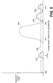
- FIG. 5 illustrates examples of a main exhaust event 600, and auxiliary valve events, such as a compression-release engine braking event 610, bleeder engine braking event 620, exhaust gas recirculation event 640, and brake gas recirculation event 630, which may be carried out by an engine valve using various embodiments of the present invention to actuate engine valves for main and auxiliary valve events.
- auxiliary valve events such as a compression-release engine braking event 610, bleeder engine braking event 620, exhaust gas recirculation event 640, and brake gas recirculation event 630
- engine braking systems may control the flow of exhaust gas to incorporate the principles of compression-release type braking, exhaust gas recirculation, exhaust pressure regulation, and/or bleeder type braking.
- the exhaust valves may be selectively opened to convert, at least temporarily, a power producing internal combustion engine into a power absorbing air compressor.
- a piston travels upward during its compression stroke, the gases that are trapped in the cylinder may be compressed. The compressed gases may oppose the upward motion of the piston.
- at least one exhaust valve may be opened to release the compressed gases in the cylinder to the exhaust manifold, preventing the energy stored in the compressed gases from being returned to the engine on the subsequent expansion down-stroke. In doing so, the engine may develop retarding power to help slow the vehicle down.
- An example of a prior art compression release engine brake is provided by the disclosure of the Cummins, U.S. Pat. No. 3,220,392 (November 1965 ), which is hereby incorporated by reference.
- WO2005/019610 A1 describes an apparatus able to adjust the valve lift in inlet or exhaust valves of an internal combustion engine having the features of the preamble of claim 1.
- Said apparatus comprises a main rocker arm and a secondary rocker arm both actuated by a common cam lobe. During each revolution of the cam lobe, the secondary rocker arm interacts with a hydraulic piston which is displaceable in a hydraulic cylinder and which forms part of a hydraulic circuit having a hydraulic fluid source and which permits switching between at least two different working positions.
- the exhaust valve(s) may be held slightly open during the remaining three engine cycles (full-cycle bleeder brake) or during a portion of the remaining three engine cycles (partial-cycle bleeder brake).
- the bleeding of cylinder gases in and out of the cylinder may act to retard the engine.
- the initial opening of the braking valve(s) in a bleeder braking operation is in advance of the compression TDC (i.e., early valve actuation) and then lift is held constant for a period of time.
- a bleeder type engine brake may require lower force to actuate the valve(s) due to early valve actuation, and generate less noise due to continuous bleeding instead of the rapid blow-down of a compression- release type brake.
- Exhaust gas recirculation (EGR) systems may allow a portion of the exhaust gases to flow back into the engine cylinder during positive power operation. EGR may be used to reduce the amount of NOx created by the engine during positive power operations. An EGR system can also be used to control the pressure and temperature in the exhaust manifold and engine cylinder during engine braking cycles. Generally, there are two types of EGR systems, internal and external. External EGR systems recirculate exhaust gases back into the engine cylinder through an intake valve(s). Internal EGR systems recirculate exhaust gases back into the engine cylinder through an exhaust valve(s) and/or an intake valve(s). Embodiments of the present invention primarily concern internal EGR systems.
- Brake gas recirculation (BGR) systems may allow a portion of the exhaust gases to flow back into the engine cylinder during engine braking operation. Recirculation of exhaust gases back into the engine cylinder during the intake stroke, for example, may increase the mass of gases in the cylinder that are available for compression-release braking. As a result, BGR may increase the braking effect realized from the braking event.
- Applicants have developed an innovative system for actuating first and second engine valves associated with the same engine cylinder, comprising: a rocker arm shaft; a means for imparting primary valve actuation motion; a primary rocker arm disposed on the rocker arm shaft, said primary rocker arm being adapted to actuate the first and second engine valves and receive motion from the means for imparting primary valve actuation motion; a means for imparting auxiliary valve actuation motion; an auxiliary rocker arm disposed adjacent to the primary rocker arm, said auxiliary rocker arm being adapted to receive motion from the means for imparting auxiliary valve actuation motion; a master piston disposed in a master piston bore in the primary rocker arm; a slave piston disposed in a slave piston bore in the primary rocker arm, said slave piston positioned so as to provide auxiliary valve actuation motion to only the first of the first and second engine valves; a control valve disposed in a control valve bore in the primary rocker arm; and a hydraulic
- Applicants have further developed an innovative system for actuating first and second engine valves comprising: a rocker arm shaft; a primary rocker arm disposed on the rocker arm shaft, said primary rocker arm having a master piston boss extending laterally from a main body of the primary rocker arm; an auxiliary rocker arm disposed adjacent to the main body of the primary rocker arm on a side of the primary rocker arm from which the master piston boss extends; a master piston disposed in a master piston bore in the master piston boss; a slave piston disposed in a slave piston bore in the main body of the primary rocker arm; a valve bridge extending between the first and second engine valves, and having a center surface adapted to contact the primary rocker arm actuation end, said valve bridge further having a side opening extending through a first end of the valve bridge above the first engine valve; a sliding pin disposed in the valve bridge side opening and extending between and contacting the first engine valve and the slave piston; and a hydraulic circuit connecting the master piston bore, the slave piston bore and
- Applicants have still further developed an innovative method of actuating first and second engine valves for primary and auxiliary valve actuation events using a primary rocker arm, an auxiliary rocker arm mounted adjacent to the primary rocker arm, and a master-slave hydraulic lost motion system incorporated into the primary rocker arm, said method comprising the steps of: actuating the first and second engine valves for a primary valve actuation event responsive to motion imparted from a first valve train element to the primary rocker arm during a primary valve actuation mode of engine operation; applying hydraulic fluid to the master-slave hydraulic lost motion system to extend master and slave pistons from the primary rocker arm during a time that an auxiliary valve actuation event is to be imparted to only the first of the first and second engine valves; and actuating only the first of the first and second engine valves for an auxiliary valve actuation event using the master-slave hydraulic lost motion system responsive to motion imparted from a second valve train element to the auxiliary rocker arm during an auxiliary valve actuation mode of engine
- Fig. 1 is a top view of a primary rocker arm 100 which may be referred to as an exhaust rocker arm herein, but which is not limited to being an exhaust rocker arm.
- An auxiliary (or offset) rocker arm 200 is mounted adjacent to the primary rocker arm 100.
- Fig. 2 is a side view in partial cross-section of the exhaust rocker arm 100 taken along cut line A-A in Fig. 1 .
- Fig. 3 is a side view in partial cross-section of the auxiliary rocker arm 200 taken along cut line B-B in Fig. 1 .
- the engine valves 400 referenced constitute poppet-type valves that are used to control communication between the combustion chambers (e.g., cylinders) in an engine and aspirating (e.g., intake and exhaust) manifolds.
- the system includes a rocker arm shaft 500 on which the primary and auxiliary rocker arms 100 and 200 may be disposed.
- the primary and auxiliary rocker arms 100 and 200 may each be mounted on their own rocker shaft.
- the primary and auxiliary rocker arms 100 and 200 may be pivoted about the rocker arm shaft 500 as a result of motion imparted to them by a camshaft 300 or some other motion imparting means.
- both it and the auxiliary rocker arm 200 may be adapted to actuate engine valves, such as an exhaust valves 400, by contacting them directly (not shown) or through a valve bridge 450 (shown).
- the auxiliary rocker arm 200 is adapted to selectively actuate at least one exhaust valve 400 by contacting a master piston 114 provided in the exhaust rocker arm 100 which is in hydraulic communication with a slave piston 172 in the exhaust rocker arm, and which in turn acts on a single exhaust valve of a set of two or more exhaust valves associated with the same engine cylinder through a sliding pin 460.
- the rocker arm shaft 500 may include one or more internal passages for the delivery of hydraulic fluid, such as engine oil, to the rocker arms mounted thereon.
- the rocker arm shaft 500 may include a control fluid supply passage 520.
- the control fluid supply passage 520 may provide hydraulic fluid to the master-slave hydraulic circuit in the exhaust rocker arm 100 through a rocker shaft passage 510.
- a solenoid control valve (not shown) may control the supply of low pressure hydraulic fluid to the control fluid supply passage 520.
- the exhaust rocker arm 100 includes a rocker shaft bore 104 extending laterally through a central portion of the rocker arm.
- the rocker shaft bore 104 may be adapted to receive the rocker arm shaft 500.
- the rocker shaft bore 104 may include one or more ports formed in the wall thereof to receive fluid from the control fluid supply passage 520 formed in the rocker arm shaft 500.
- the exhaust rocker arm 100 may include a valve actuation end 106 having a lash adjustment screw 108.
- the lash adjustment screw 108 may protrude from the bottom of the valve actuation end 106 and permit adjustment of the lash space between the valve actuation end 106 of the exhaust rocker arm and the exhaust valve bridge 450.
- the lash adjustment screw may be locked in place by a nut.
- a self-adjusting hydraulic lash adjuster may be substituted for the manually-adjustable lash adjustment screw, or lash adjustment may not be provided at all.
- a master piston boss 110 may extend laterally from the valve actuation end 106 of the main body of the exhaust rocker arm so that it is positioned below the valve actuation end 206 of the auxiliary rocker arm 200.
- Fig. 3 is a side view in cross-section which shows the master piston boss 110.
- a master piston bore 112 may be formed in the boss 110 and a master piston 114 may be slidably disposed in the master piston bore 112.
- a master piston retaining cup 116 may be located near the open end of the master piston bore 112.
- the retaining cup 116 may have a central opening through which the master piston 114 may extend.
- the retaining cup 116 may be prevented from sliding out of the master piston bore 112 by a retaining washer.
- An optional spring 120 may extend between the retaining cup 116 and a shoulder provided on the master piston 114 so that the master piston is biased into the master piston bore 112.
- a fluid passage 164 may connect the master piston bore to a slave piston bore 170 or the fluid passage
- the exhaust rocker arm 100 may include a slave piston bore 170 adjacent to the master piston bore 112 and a slave piston 172 may be slidably disposed in the slave piston bore 170.
- a slave piston retaining cup 174 may be located near the open end of the slave piston bore 170.
- the retaining cup 174 may have a central opening through which the slave piston 172 may extend.
- the retaining cup 174 may be prevented from sliding out of the slave piston bore 170 by a retaining washer.
- An optional spring 176 may extend between the retaining cup 174 and a shoulder provided on the slave piston 172 so that the slave piston is biased into the slave piston bore 170.
- the fluid passage 164 may connect the slave piston bore 170 or the passage 162 extending from the slave piston bore to the master piston bore 112.
- a lash adjustment screw 178 may extend through the exhaust rocker arm 100 to contact the slave piston 172.
- the lash adjustment screw 178 may protrude from the top of the valve actuation end 106 of the exhaust rocker arm and permit adjustment of the lash space between the lower end of the slave piston 172 and the sliding pin 460 in the exhaust valve bridge 450.
- the lash adjustment screw may be locked in place by a nut.
- a self-adjusting hydraulic lash adjuster may be substituted for the manually-adjustable lash adjustment screw, or lash adjustment may not be provided at all.
- the exhaust rocker arm 100 may also include a control valve bore 124 at the end of the rocker arm proximal to the valve actuation end 106.
- a control valve piston 130 may be disposed in a control valve bore 124.
- the control valve piston 130 may control the supply of hydraulic fluid to the master and slave hydraulic circuit which includes the master and slave piston bores 112 and 170, and the fluid passages 162 and 164.
- the control valve bore may be oriented vertically, as shown in Figs. 2 and 4 , or in an alternative embodiment, in some other orientation, such as horizontally.
- Fig. 4 shows the details of the control valve piston 130 used in the first embodiment of the present invention.
- the control valve piston 130 may be a cylindrically shaped element with one or more internal passages, and which may incorporate an internal control check valve 140.
- the check valve 140 may permit fluid to pass from the control fluid passage 160 to the supply fluid passage 162, but not in the reverse direction.
- the control valve piston 130 may be spring biased by one or more control valve springs 133 into the control valve bore 124 into the bottom 135 of the control valve bore.
- a central internal passage may extend axially from the inner end of the control valve piston 130 towards the middle of the control valve piston where the control check valve 140 may be located.
- the central internal passage in the control valve piston 130 may communicate with one or more passages extending across the diameter of the control valve piston 130.
- the passages extending through the control valve piston 130 may selectively register with a port that connects the side wall of the control valve bore with the second fluid passage 162.
- low pressure fluid may flow from the first fluid passage 160, through the control valve piston 130, and into the second fluid passage 162 to fill the master-slave hydraulic circuit.
- the exhaust rocker arm 100 may include one or more internal passages 160, 162 and 164 for the delivery of hydraulic fluid through the exhaust rocker arm to fill the master-slave hydraulic circuit contained therein.
- a port at the end of the first fluid passage 160 may communicate with the rocker shaft bore 104 and may register with the control fluid supply passage 520 provided in the rocker arm shaft 500 when the exhaust rocker arm is mounted on the rocker arm shaft.
- the first fluid passage 160 may extend between the rocker shaft bore 104 and the control valve bore 124.
- the second fluid passage 162 may extend through the exhaust rocker arm 100 from the control valve bore 124 to the slave piston bore 170.
- the third fluid passage 164 may extend from the master piston bore 112 to the slave piston bore 170 or the second fluid passage 162.
- an exhaust rocker cam roller 102 may be connected to the exhaust rocker arm 100.
- the exhaust rocker cam roller 102 may contact an exhaust cam 310 (i.e., means for imparting primary valve actuation) provided on the cam shaft 300.
- the exhaust cam 310 may include one or more lobes, including a lobe adapted to produce a primary valve opening event, such as a main exhaust event, by imparting a primary valve actuation motion to the exhaust rocker arm 100. It is appreciated that the primary valve actuation motion may be imparted to the exhaust rocker arm 100 by any number of alternative valve train elements, including but not limited to cams, push tubes, rocker arms, levers, hydraulic and electro-mechanical actuators, and the like.
- the auxiliary rocker arm 200 includes a rocker shaft bore 204 extending laterally through a central portion of the offset rocker arm.
- the rocker shaft bore 204 may be adapted to receive the rocker arm shaft 500.
- the auxiliary rocker arm 200 may further include a valve actuation end 206 and a lash adjustment screw 208.
- the lash adjustment screw 208 may protrude from the bottom of the valve actuation end 206 and permit adjustment of the lash space between the valve actuation end 206 of the auxiliary rocker arm and the master piston 114.
- the lash adjustment screw 208 may be locked in place by a nut.
- a hydraulic or other self-adjusting lash adjuster may be substituted for the lash adjustment screw 208.
- An auxiliary rocker cam roller 202 may be connected to the offset rocker arm 200.
- the auxiliary rocker cam roller 202 may contact an auxiliary cam 320 (i.e., means for providing auxiliary valve actuation) provided on the cam shaft 300.
- the auxiliary cam 320 may include one or more cam lobes such as for example, an engine braking cam lobe 330, an exhaust gas recirculation (EGR) cam lobe 340, and/or a brake gas recirculation (BGR) cam lobe 350 adapted to impart one or more auxiliary valve actuation motions to the auxiliary rocker arm 200.
- EGR exhaust gas recirculation
- BGR brake gas recirculation
- auxiliary valve actuation motions may be imparted to the auxiliary actuator rocker arm 200 by any number of alternative valve train elements, including but not limited to cams, push tubes, rocker arms, levers, hydraulic and electro-mechanical actuators, and the like.
- the engine braking cam lobe 330 may be adapted to provide compression-release, bleeder, or partial bleeder engine braking.
- Compression-release engine braking involves opening an exhaust valve (or an auxiliary engine valve) near the top dead center position for the engine piston on compression strokes (and/or exhaust strokes for two-cycle braking) for the piston.
- Bleeder engine braking involves opening an exhaust valve for the complete engine cycle; and partial bleeder engine braking involves opening an exhaust valve for a significant portion of the engine cycle.
- the optional EGR lobe may be used to provide an EGR event during a positive power mode of engine operation.
- the optional BGR lobe may be used to provide a BGR event during an engine braking mode of engine operation.
- the valve actuation motions provided by the engine braking lobe 330, the EGR lobe 340, and the BGR lobe 350 are intended to be examples of auxiliary valve actuation motions that may be provided by the auxiliary rocker arm 200.
- a mousetrap type spring 210 may engage the auxiliary rocker arm 200 and the rocker shaft 500. As shown, the spring 210 may bias the auxiliary rocker arm 200 toward the cam shaft 300. The spring 210 may have sufficient strength to maintain the auxiliary rocker arm 200 in contact with the auxiliary cam 320 throughout the rotation of the cam shaft. In an alternative embodiment, the spring 210 may bias the auxiliary rocker arm 200 toward the master piston 114. In such embodiments, extension of the master piston 114 from the piston bore 112 may cause the auxiliary rocker arm 200 to rotate backward against the bias of the spring 210 so that it may contact the auxiliary cam 320 only when the master piston is hydraulically extended.
- the rocker arms may include an intake rocker arm 100.
- the intake rocker arm 100 may be adapted to actuate an engine valve, such as an intake valve 400, by contacting it directly or through a valve bridge.
- the auxiliary rocker arm 200 may be adapted to selectively actuate at least one intake valve 400 by contacting the intake rocker arm 100, and acting through the intake rocker arm on the intake valve.
- an intake cam may impart primary valve actuation motion to the intake rocker arm to provide a main intake event
- an auxiliary cam may impart auxiliary valve actuation motion to the auxiliary rocker arm 200 to provide auxiliary intake events, such as, for example, exhaust gas recirculation, and/or brake gas recirculation.
- engine operation causes the cam shaft 300 to rotate.
- the rotation of the exhaust cam 310 causes the exhaust rocker arm 100 to pivot about the rocker shaft 500 and actuate the exhaust valves 400 for main exhaust events in response to interaction between the main exhaust lobe 315 on the exhaust cam and the exhaust cam roller 102.
- each lobe on the auxiliary cam 320 may cause the auxiliary rocker arm 200 to pivot about the rocker shaft 500 toward the master piston 114.
- fluid pressure in the control fluid supply passage 520 may be vented or reduced, which in turn may cause fluid pressure in the control fluid passage 160 (see Figs. 2 and 4 ) to vent or recede.
- the internal fluid passages in the control valve piston 130 may cease to register with the port connecting the control valve bore 124 to the second fluid passage 162 as the control valve 130 translates into the control valve bore under the influence of the control valve spring 133. Fluid in the second fluid passage 162 may then vent past the rear of the control valve piston 130 and out of the control valve bore 124.
- the master piston 114 may collapse into the master piston bore 112 under the influence of the master piston spring 120,.
- the auxiliary rocker arm 200 may be biased toward the auxiliary cam 320 by the spring 210.
- a lash space may exist between the valve actuation end 206 of the auxiliary rocker arm 200 and the master piston when the auxiliary cam 320 is at base circle and fluid pressure in the fluid supply passage 520 is vented or reduced.
- this lash space prevents the auxiliary rocker arm 200 from engaging the master piston 114 when the auxiliary rocker arm is pivoted by the lobe or lobes on the auxiliary cam 320.
- movement of the auxiliary rocker arm 200 in response to the auxiliary cam 320 may not produce any actuation of the master piston 114.
- the fluid pressure in the control fluid supply passage 520 may be increased.
- a solenoid actuated valve (not shown) may be used to control the application of increased fluid pressure in the control fluid supply passage 520.
- Increased fluid pressure in the control fluid supply passage 520 is applied through the first fluid passage 160 in the exhaust rocker arm 100 to the control valve piston 130.
- the control valve piston 130 may be displaced in the control valve bore 124 into an "engine brake on" position (shown in Fig. 4 ), wherein the internal fluid passages in the control valve piston 130 registerwith the second fluid passage 162.
- the check valve 140 may preventfluid that enters the second fluid passage 162 from flowing back through the control valve piston 130. Fluid pressure in the second fluid passage 162 and third fluid passage 164 may be sufficient to overcome the bias force of the master piston spring 120. As a result, the master piston 114 may extend out of the bore 112 and take up the lash space between the master piston and the auxiliary rocker arm actuation en 206 when the auxiliary cam 320 is at base circle. As long as low pressure fluid maintains the control valve piston 130 in the "engine brake on" position, the master piston 114 may be in a hydraulically extended position.
- auxiliary rocker arm 200 pivoting of the auxiliary rocker arm 200 by the auxiliary cam 320 may displace the master piston 114, which in turn displaces the slave piston 172 to produce a valve actuation for the exhaust valve 400 that is in contact with the sliding pin 460.
- the valve actuation may correspond to each lobe on the auxiliary cam (i.e., lobes 330, 340, and/or 350 ) because there is reduced or no lash space between the auxiliary rocker arm and the master piston.
- control fluid supply passage 520 When auxiliary exhaust valve actuation is no longer desired, pressure in the control fluid supply passage 520 may be reduced or vented and the control valve piston 130 will return to an "engine brake off" position. Fluid in the master piston bore 112 may then vent back through the third and second fluid passages 162 and 164 and out of the control valve bore 124.
- the exhaust rocker arm 100 could be implemented as an intake rocker arm, or an auxiliary rocker arm, without departing from the intended scope of the invention.
- various embodiments of the invention may or may not include a means for biasing the auxiliary rocker arm 200 toward either the auxiliary cam 320, or the master piston 114.
- the designation of a rocker arm as a "auxiliary" rocker arm is not intended to be limiting to its size or shape relative to any other rocker arm.
Claims (19)
- Système d'actionnement de première et seconde soupapes de moteur associées au même cylindre de moteur, comprenant :un arbre de culbuteur (500) ;un moyen pour communiquer un mouvement d'actionnement de soupape principale (310) ;un culbuteur principal (100) disposé sur l'arbre de culbuteur, ledit culbuteur principal étant adapté à actionner les première et seconde soupapes de moteur (400) et à recevoir un mouvement depuis le moyen de communication de mouvement d'actionnement de soupape principale ;un culbuteur auxiliaire (200) disposé de manière adjacente au culbuteur principal, un piston maître (114) disposé dans un alésage de piston maître (112) dans le culbuteur principal et agencé de façon à recevoir le mouvement d'actionnement de soupape auxiliaire depuis le culbuteur auxiliaire ;un piston esclave (172) disposé dans un alésage de piston esclave (170) dans le culbuteur principal,une soupape de commande (130) disposée dans un alésage de soupape de commande (124) dans le culbuteur principal ; etun circuit hydraulique (162, 164) reliant l'alésage de piston maître, l'alésage de piston esclave et l'alésage de soupape de commande,caractérisé parun moyen pour communiquer un mouvement d'actionnement de soupape auxiliaire (320) ;ledit culbuteur auxiliaire étant adapté à recevoir un mouvement depuis le moyen de communication de mouvement d'actionnement de soupape auxiliaire ;et ledit piston esclave est positionné de façon à fournir un mouvement d'actionnement de soupape auxiliaire seulement à la première des première et seconde soupapes de moteur.
- Système selon la revendication 1, comprenant en outre :une tige coulissante (460) disposée entre le piston esclave et la première soupape de moteur, dans lequel le mouvement d'actionnement de soupape auxiliaire est transféré du culbuteur auxiliaire à la première soupape de moteur par l'intermédiaire du mouvement du piston maître, du piston esclave et de la tige coulissante.
- Système selon la revendication 2, comprenant en outre :un pontet (450) s'étendant entre les première et seconde soupapes de moteur, ledit pontet ayant une ouverture latérale s'étendant à travers une première extrémité du pontet au-dessus de la première soupape de moteur, dans lequel ladite tige coulissante est disposée dans l'ouverture côté pontet.
- Système selon la revendication 1, comprenant en outre :un pontet (450) s'étendant entre les première et seconde soupapes de moteur, ledit pontet ayant une ouverture latérale s'étendant à travers une première extrémité du pontet au-dessus de la première soupape de moteur ; etune tige coulissante (460) disposée dans l'ouverture côté pontet et s'étendant entre la première soupape de moteur et le piston esclave.
- Système selon la revendication 4, comprenant en outre :un bossage de piston maître (110) s'étendant latéralement depuis le corps principal du culbuteur principal, ledit bossage de piston maître étant positionné en dessous d'une extrémité d'actionnement de soupape (206) du culbuteur auxiliaire et contenant l'alésage de piston maître.
- Système selon la revendication 3, comprenant en outre :un bossage de piston maître (110) s'étendant latéralement depuis le corps principal du culbuteur principal, ledit bossage de piston maître étant positionné en dessous d'une extrémité d'actionnement de soupape (206) du culbuteur auxiliaire et contenant l'alésage de piston maître.
- Système selon la revendication 1, comprenant en outre :un bossage de piston maître (110) s'étendant latéralement depuis le corps principal du culbuteur principal, ledit bossage de piston maître étant positionné en dessous d'une extrémité d'actionnement de soupape (206) du culbuteur auxiliaire et contenant l'alésage de piston maître.
- Système selon la revendication 4, dans lequel le piston maître s'étend depuis la surface supérieure du culbuteur principal et le piston esclave s'étend depuis la surface inférieure du culbuteur principal.
- Système selon la revendication 3, dans lequel le piston maître s'étend depuis la surface supérieure du culbuteur principal et le piston esclave s'étend depuis la surface inférieure du culbuteur principal.
- Système selon la revendication 1, dans lequel le piston maître s'étend depuis la surface supérieure du culbuteur principal et le piston esclave s'étend depuis la surface inférieure du culbuteur principal.
- Système selon la revendication 1, comprenant en outre :un contrôleur de freinage de moteur ; etun moyen pour fournir (160) à l'alésage de piston maître, à l'alésage de piston esclave et au circuit hydraulique, un fluide hydraulique en réponse à un signal fourni par le contrôleur de freinage de moteur.
- Système selon la revendication 1, comprenant en outre une soupape antiretour (140) disposée dans la soupape de commande.
- Système selon la revendication 1, comprenant en outre un passage de fourniture de fluide de commande (160) prévu dans le culbuteur et relié au circuit hydraulique.
- Système selon la revendication 1, comprenant en outre un ressort de piston maître (120) poussant le piston maître dans l'alésage de piston maître.
- Système selon la revendication 1, comprenant en outre un ressort de piston esclave (176) poussant le piston esclave dans l'alésage de piston esclave.
- Système selon la revendication 1, comprenant en outre un moyen pour pousser le culbuteur auxiliaire vers le piston maître.
- Système selon la revendication 1, dans lequel le mouvement d'actionnement de soupape auxiliaire est choisi dans le groupe constitué de : un mouvement de freinage de moteur (610, 620), un mouvement de remise en circulation des gaz d'échappement (640), un mouvement d'admission auxiliaire et un mouvement de remise en circulation des gaz de frein (630).
- Procédé d'actionnement de première et seconde soupapes de moteur (400) pour des événements d'actionnement de soupapes principale et auxiliaire utilisant un culbuteur principal (100), un culbuteur auxiliaire (200) monté de manière adjacente au culbuteur principal, et un système hydraulique maître-esclave à mouvement perdu (114, 172, 162, 164) incorporé dans le culbuteur principal, ledit procédé comprenant les étapes consistant à :actionner les première et seconde soupapes de moteur pour un événement d'actionnement de soupape principale en réaction à un mouvement communiqué par un premier élément de train de soupape (310) au culbuteur principal pendant un mode de fonctionnement du moteur d'actionnement de soupape principale ; etappliquer un fluide hydraulique au système hydraulique maître-esclave à mouvement perdu (114, 172) pour étendre les pistons maître et esclave (114, 172) depuis le culbuteur principal pendant une durée telle qu'un événement d'actionnement de soupape auxiliaire doit être communiqué seulement à la première des première et seconde soupapes de moteur ;caractérisé en ce qu'il comprend en outre les étapes consistant àactionner seulement la première des première et seconde soupapes de moteur pour un événement d'actionnement de soupape auxiliaire utilisant le système hydraulique maître-esclave à mouvement perdu en réaction à un mouvement communiqué par un second élément de train de soupape (310) au culbuteur auxiliaire pendant un mode de fonctionnement du moteur d'actionnement de soupape auxiliaire.
- Procédé selon la revendication 18, dans lequel l'événement d'actionnement de soupape auxiliaire est choisi dans le groupe constitué de : un événement de freinage de moteur (610, 620), un événement de remise en circulation des gaz d'échappement (640), un événement d'admission auxiliaire et un événement de remise en circulation des gaz de frein (630).
Applications Claiming Priority (2)
| Application Number | Priority Date | Filing Date | Title |
|---|---|---|---|
| US201161490544P | 2011-05-26 | 2011-05-26 | |
| PCT/US2012/039599 WO2012162616A1 (fr) | 2011-05-26 | 2012-05-25 | Ensemble de culbuteurs principal et auxiliaire pour commande des soupapes de moteur |
Publications (3)
| Publication Number | Publication Date |
|---|---|
| EP2715076A1 EP2715076A1 (fr) | 2014-04-09 |
| EP2715076A4 EP2715076A4 (fr) | 2015-03-04 |
| EP2715076B1 true EP2715076B1 (fr) | 2016-04-20 |
Family
ID=47217777
Family Applications (1)
| Application Number | Title | Priority Date | Filing Date |
|---|---|---|---|
| EP12789392.3A Active EP2715076B1 (fr) | 2011-05-26 | 2012-05-25 | Ensemble de culbuteurs principal et auxiliaire pour commande des soupapes de moteur |
Country Status (7)
| Country | Link |
|---|---|
| US (2) | US8627791B2 (fr) |
| EP (1) | EP2715076B1 (fr) |
| JP (1) | JP2014515456A (fr) |
| KR (1) | KR101569663B1 (fr) |
| CN (1) | CN103597174B (fr) |
| BR (1) | BR112013029941B1 (fr) |
| WO (1) | WO2012162616A1 (fr) |
Cited By (1)
| Publication number | Priority date | Publication date | Assignee | Title |
|---|---|---|---|---|
| US11506092B2 (en) | 2017-12-04 | 2022-11-22 | Eaton Intelligent Power Limited | Engine brake rocker arm having biasing configuration |
Families Citing this family (45)
| Publication number | Priority date | Publication date | Assignee | Title |
|---|---|---|---|---|
| CN102588030B (zh) * | 2011-01-05 | 2016-08-10 | 上海尤顺汽车部件有限公司 | 发动机的辅助气门驱动机构 |
| GB201211534D0 (en) | 2012-06-29 | 2012-08-08 | Eaton Srl | Valve bridge |
| WO2014047643A1 (fr) * | 2012-09-24 | 2014-03-27 | Jacobs Vehicle Systems, Inc. | Frein culbuteur à perte de mouvement intégrée avec réenclenchement automatique |
| US9068478B2 (en) | 2013-02-25 | 2015-06-30 | Jacobs Vehicle Systems, Inc. | Apparatus and system comprising integrated master-slave pistons for actuating engine valves |
| US20140283774A1 (en) * | 2013-03-22 | 2014-09-25 | Caterpillar Inc. | Rocker arm assembly and method of lubricating a valve train |
| DE102013215946A1 (de) * | 2013-08-12 | 2015-02-12 | Avl List Gmbh | Ventilbetätigungseinrichtung zur Veränderung des Ventilhubs |
| WO2015085206A1 (fr) | 2013-12-05 | 2015-06-11 | Jacobs Vehicle Systems, Inc. | Appareil et système comprenant des mécanismes d'affaissement et d'extension pour actionner des soupapes de moteur |
| US10247064B2 (en) * | 2014-02-14 | 2019-04-02 | Eaton Intelligent Power Limited | Rocker arm assembly for engine braking |
| WO2015175213A1 (fr) * | 2014-05-12 | 2015-11-19 | Borgwarner Inc. | Actionnement de soupape entrainée par vilebrequin |
| CN106536878B (zh) * | 2014-05-21 | 2019-05-31 | 伊顿(意大利)有限公司 | 具有减压式发动机制动功能的重型配气机构 |
| KR101917735B1 (ko) | 2014-06-10 | 2018-11-12 | 자콥스 비히클 시스템즈, 인코포레이티드. | 내연 기관의 보조 운동 소스와 주 운동 부하 경로 사이의 링키지 |
| KR101911011B1 (ko) | 2014-09-18 | 2018-10-23 | 자콥스 비히클 시스템즈, 인코포레이티드. | 유압식 래시 어저스터를 포함하는 밸브 트레인과의 사용을 위한 밸브 브리지 내의 로스트 모션 조립체 |
| US10605131B2 (en) * | 2014-09-18 | 2020-03-31 | Eaton Intelligent Power Limited | Rocker arm assembly for engine braking |
| CN104712397B (zh) * | 2015-03-05 | 2020-08-25 | 上海尤顺汽车部件有限公司 | 一种复合摇臂发动机制动装置 |
| EP3207226A4 (fr) * | 2014-10-15 | 2018-05-16 | Shanghai Universoon Autoparts Co., Ltd | Procédé et système de freinage moteur |
| US11092042B2 (en) * | 2015-01-21 | 2021-08-17 | Eaton Intelligent Power Limited | Rocker arm assembly with valve bridge |
| GB2536927B (en) * | 2015-03-31 | 2020-08-26 | Eaton Intelligent Power Ltd | Self-retracting hydraulic engine brake system |
| BR112017024460A2 (pt) * | 2015-05-18 | 2018-07-24 | Eaton Srl | conjunto de balancim de válvula de exaustão |
| USD808872S1 (en) | 2015-09-11 | 2018-01-30 | Eaton S.R.L. | Rocker arm for engine brake |
| USD839310S1 (en) | 2015-09-11 | 2019-01-29 | Eaton Intelligent Power Limited | Valve bridge |
| US10526936B2 (en) | 2015-09-29 | 2020-01-07 | Jacobs Vehicle Systems, Inc. | System for engine valve actuation comprising lash-prevention valve actuation motion |
| CN106640257B (zh) * | 2015-10-29 | 2019-09-27 | 上海尤顺汽车部件有限公司 | 载荷可控的发动机制动装置和发动机制动方法 |
| DE102015016526A1 (de) * | 2015-12-19 | 2017-06-22 | Daimler Ag | Verfahren zum Betreiben einer Hubkolben-Verbrennungskraftmaschine |
| US10794242B2 (en) | 2016-03-14 | 2020-10-06 | Volvo Truck Corporation | Device for controlling at least one valve in an internal combustion engine |
| SE539832C2 (en) * | 2016-04-28 | 2017-12-12 | Scania Cv Ab | A valve drive for an internal combustion engine with variable control of valves |
| CN113047921B (zh) * | 2016-05-10 | 2022-11-29 | 伊顿智能动力有限公司 | 模块化排气阀门摇臂组件及装配其的方法 |
| EP3475540A1 (fr) | 2016-06-25 | 2019-05-01 | Eaton Intelligent Power Limited | Ensemble de commande de soupapes |
| AT518933B1 (de) * | 2016-07-20 | 2018-07-15 | Avl List Gmbh | Brennkraftmaschine mit einer ventilbetätigungseinrichtung |
| US10683778B2 (en) * | 2016-08-31 | 2020-06-16 | Jacobs Vehicle Systems, Inc. | Removable valve bridges and valve actuation systems including the same |
| KR101865738B1 (ko) * | 2016-12-09 | 2018-07-04 | 현대자동차 주식회사 | 가변 밸브 리프트 장치 |
| CN106545371B (zh) * | 2017-01-23 | 2022-03-22 | 广西玉柴机器股份有限公司 | 发动机凸轮轴的排气凸轮 |
| US11549404B2 (en) | 2017-08-24 | 2023-01-10 | Eaton Intelligent Power Limited | Ball engine decompression mechanism |
| CN111033003B (zh) | 2017-08-24 | 2022-04-05 | 伊顿智能动力有限公司 | 球形引擎制动机构 |
| KR102335529B1 (ko) * | 2017-09-12 | 2021-12-03 | 현대자동차주식회사 | 엔진 브레이크 장치 |
| US11255226B2 (en) | 2017-11-10 | 2022-02-22 | Jacobs Vehicle Systems, Inc. | Lash adjuster control in engine valve actuation systems |
| EP3707353A4 (fr) * | 2017-11-10 | 2021-08-11 | Jacobs Vehicle Systems, Inc. | Réglage de jeu dans des systèmes de moteur à mouvement perdu |
| CN108266241B (zh) * | 2018-02-07 | 2023-05-26 | 广西玉柴机器股份有限公司 | 增大制动功率的发动机凸轮轴的排气凸轮 |
| US11149599B2 (en) * | 2018-03-26 | 2021-10-19 | Jacobs Vehicle Systems, Inc. | Systems and methods for IEGR using secondary intake valve motion and lost-motion reset |
| KR20210037901A (ko) * | 2019-09-30 | 2021-04-07 | 현대자동차주식회사 | 압축 완화형 엔진 브레이크 장치 및 이의 작동 방법 |
| CN110863882A (zh) * | 2019-12-20 | 2020-03-06 | 浙江九隆机械有限公司 | 一种制动器 |
| US10954869B1 (en) * | 2020-02-18 | 2021-03-23 | Ford Global Technologies, Llc | System and method to reduce engine hydrocarbon emissions |
| US11377980B2 (en) | 2020-12-02 | 2022-07-05 | Jiangsu Jointek Precision Machinery Co., Ltd | Self-resetting single-valve double-piston hydraulic drive device and method for overhead cam engine |
| CN112177702B (zh) * | 2020-12-02 | 2021-03-12 | 江苏卓联精密机械有限公司 | 顶置凸轮发动机自复位单气门双活塞液压驱动装置及方法 |
| WO2022218114A1 (fr) * | 2021-04-14 | 2022-10-20 | 上海尤顺汽车技术有限公司 | Système de freinage à quatre temps de moteur, procédé et système de levée de soupape de freinage de moteur |
| WO2023037321A1 (fr) * | 2021-09-10 | 2023-03-16 | Jacobs Vehicle Systems, Inc. | Ensemble culbuteur de fermeture de soupape en deux étapes |
Family Cites Families (16)
| Publication number | Priority date | Publication date | Assignee | Title |
|---|---|---|---|---|
| US3220392A (en) | 1962-06-04 | 1965-11-30 | Clessie L Cummins | Vehicle engine braking and fuel control system |
| US4711210A (en) * | 1986-12-29 | 1987-12-08 | Cummins Engine Company, Inc. | Compression braking system for an internal combustion engine |
| DE4142197A1 (de) * | 1991-12-20 | 1993-04-08 | Daimler Benz Ag | Kipphebelanordnung fuer einen ventiltrieb mit variabler ventilbetaetigungszeit bei brennkraftmaschinen |
| US5462025A (en) * | 1994-09-28 | 1995-10-31 | Diesel Engine Retarders, Inc. | Hydraulic circuits for compression release engine brakes |
| WO1997006355A1 (fr) * | 1995-08-08 | 1997-02-20 | Diesel Engine Retarders, Inc. | Moteurs a combustion interne a commande combinee de came et de soupape electro-hydaulique |
| US6386160B1 (en) * | 1999-12-22 | 2002-05-14 | Jenara Enterprises, Ltd. | Valve control apparatus with reset |
| SE523849C2 (sv) | 2001-10-11 | 2004-05-25 | Volvo Lastvagnar Ab | Avgasventilmekanism i förbränningsmotor |
| JP4021730B2 (ja) * | 2001-12-10 | 2007-12-12 | 日野自動車株式会社 | 可変バルブタイミングシステム |
| KR100751607B1 (ko) * | 2002-09-12 | 2007-08-22 | 디이젤 엔진 리타더스, 인코포레이티드 | 내적 배기 가스 재순환 시스템 및 방법 |
| US20040065285A1 (en) * | 2002-10-04 | 2004-04-08 | Ali Uludogan | Variable engine valve actuator |
| TWI222489B (en) * | 2002-12-17 | 2004-10-21 | Mitsubishi Motors Corp | Valve driving device of internal combustion engine |
| SE525678C2 (sv) * | 2003-08-25 | 2005-04-05 | Volvo Lastvagnar Ab | Anordning vid förbränningsmotor |
| EP1761686B1 (fr) * | 2004-05-06 | 2012-08-08 | Jacobs Vehicle Systems, Inc. | Culbuteurs decale et primaire pour actionnement de soupape de moteur |
| JP2007537396A (ja) * | 2004-05-14 | 2007-12-20 | ジェイコブス ビークル システムズ、インコーポレイテッド | エンジン・バルブ作動用のロッカー・アーム・システム |
| CN102414403B (zh) * | 2009-04-27 | 2015-09-09 | 雅各布斯车辆系统公司 | 专用的摇臂型发动机制动器 |
| US7712449B1 (en) * | 2009-05-06 | 2010-05-11 | Jacobs Vehicle Systems, Inc. | Lost motion variable valve actuation system for engine braking and early exhaust opening |
-
2012
- 2012-05-25 CN CN201280025665.7A patent/CN103597174B/zh active Active
- 2012-05-25 EP EP12789392.3A patent/EP2715076B1/fr active Active
- 2012-05-25 BR BR112013029941-0A patent/BR112013029941B1/pt active IP Right Grant
- 2012-05-25 KR KR1020137034608A patent/KR101569663B1/ko active IP Right Grant
- 2012-05-25 WO PCT/US2012/039599 patent/WO2012162616A1/fr active Application Filing
- 2012-05-25 US US13/481,026 patent/US8627791B2/en active Active
- 2012-05-25 JP JP2014512142A patent/JP2014515456A/ja active Pending
-
2013
- 2013-12-20 US US14/137,142 patent/US20140109848A1/en not_active Abandoned
Cited By (1)
| Publication number | Priority date | Publication date | Assignee | Title |
|---|---|---|---|---|
| US11506092B2 (en) | 2017-12-04 | 2022-11-22 | Eaton Intelligent Power Limited | Engine brake rocker arm having biasing configuration |
Also Published As
| Publication number | Publication date |
|---|---|
| KR20140036266A (ko) | 2014-03-25 |
| BR112013029941A2 (pt) | 2017-08-08 |
| KR101569663B1 (ko) | 2015-11-17 |
| US20140109848A1 (en) | 2014-04-24 |
| WO2012162616A1 (fr) | 2012-11-29 |
| US20120298057A1 (en) | 2012-11-29 |
| CN103597174B (zh) | 2016-07-27 |
| CN103597174A (zh) | 2014-02-19 |
| EP2715076A4 (fr) | 2015-03-04 |
| JP2014515456A (ja) | 2014-06-30 |
| US8627791B2 (en) | 2014-01-14 |
| EP2715076A1 (fr) | 2014-04-09 |
| BR112013029941B1 (pt) | 2021-06-01 |
Similar Documents
| Publication | Publication Date | Title |
|---|---|---|
| EP2715076B1 (fr) | Ensemble de culbuteurs principal et auxiliaire pour commande des soupapes de moteur | |
| US7392772B2 (en) | Primary and offset actuator rocker arms for engine valve actuation | |
| EP2137386B1 (fr) | Frein moteur ayant un culbuteur articulé et un boîtier monté sur arbre de culbuteur | |
| EP2425105B1 (fr) | Frein de moteur à culbuteur dédié | |
| US9016249B2 (en) | Integrated lost motion rocker brake with automatic reset | |
| EP2959122B1 (fr) | Pistons de maître-cylindre et cylindre récepteur intégrés pour actionner des soupapes d'un moteur | |
| EP2427642B1 (fr) | Système d'actionnement à programme variable et mouvement perdu pour freinage de moteur et ouverture d'échappement d'air précoce | |
| EP2598727B1 (fr) | Système combiné de freinage moteur et d'actionnement de soupape à perte de mouvement de moteur à énergie positive | |
| US20050274341A1 (en) | Rocker arm system for engine valve actuation | |
| EP1733125B1 (fr) | Crosse de soupapes a systeme integre de maitrise de la perte de mouvement | |
| US8528508B2 (en) | Individual rocker shaft and pedestal mounted engine brake | |
| US20100108007A1 (en) | Rocker shaft mounted engine brake | |
| JP2001526348A (ja) | エンジン弁作動システム | |
| WO2014015292A2 (fr) | Systèmes et procédés d'ajustement de jeu hydraulique dans un moteur à combustion interne |
Legal Events
| Date | Code | Title | Description |
|---|---|---|---|
| PUAI | Public reference made under article 153(3) epc to a published international application that has entered the european phase |
Free format text: ORIGINAL CODE: 0009012 |
|
| 17P | Request for examination filed |
Effective date: 20131122 |
|
| AK | Designated contracting states |
Kind code of ref document: A1 Designated state(s): AL AT BE BG CH CY CZ DE DK EE ES FI FR GB GR HR HU IE IS IT LI LT LU LV MC MK MT NL NO PL PT RO RS SE SI SK SM TR |
|
| DAX | Request for extension of the european patent (deleted) | ||
| A4 | Supplementary search report drawn up and despatched |
Effective date: 20150204 |
|
| RIC1 | Information provided on ipc code assigned before grant |
Ipc: F01L 1/20 20060101ALI20150129BHEP Ipc: F01L 1/18 20060101ALI20150129BHEP Ipc: F01L 9/02 20060101AFI20150129BHEP Ipc: F01L 1/08 20060101ALI20150129BHEP Ipc: F01L 13/06 20060101ALI20150129BHEP Ipc: F01L 13/00 20060101ALI20150129BHEP Ipc: F02D 13/04 20060101ALI20150129BHEP Ipc: F02D 13/02 20060101ALI20150129BHEP Ipc: F01L 1/26 20060101ALI20150129BHEP Ipc: F02M 25/07 20060101ALI20150129BHEP |
|
| GRAP | Despatch of communication of intention to grant a patent |
Free format text: ORIGINAL CODE: EPIDOSNIGR1 |
|
| RIC1 | Information provided on ipc code assigned before grant |
Ipc: F01L 1/20 20060101ALI20151015BHEP Ipc: F01L 1/26 20060101ALI20151015BHEP Ipc: F02D 13/04 20060101ALI20151015BHEP Ipc: F02M 25/07 20060101ALI20151015BHEP Ipc: F02D 13/02 20060101ALI20151015BHEP Ipc: F01L 13/00 20060101ALI20151015BHEP Ipc: F01L 9/02 20060101AFI20151015BHEP Ipc: F01L 13/06 20060101ALI20151015BHEP Ipc: F01L 1/08 20060101ALI20151015BHEP Ipc: F01L 1/18 20060101ALI20151015BHEP |
|
| INTG | Intention to grant announced |
Effective date: 20151110 |
|
| GRAS | Grant fee paid |
Free format text: ORIGINAL CODE: EPIDOSNIGR3 |
|
| GRAA | (expected) grant |
Free format text: ORIGINAL CODE: 0009210 |
|
| RIC1 | Information provided on ipc code assigned before grant |
Ipc: F01L 1/18 20060101ALI20160302BHEP Ipc: F02D 13/02 20060101ALI20160302BHEP Ipc: F01L 13/00 20060101ALI20160302BHEP Ipc: F02M 26/00 20160101ALI20160302BHEP Ipc: F02D 13/04 20060101ALI20160302BHEP Ipc: F01L 1/26 20060101ALI20160302BHEP Ipc: F01L 1/20 20060101ALI20160302BHEP Ipc: F01L 13/06 20060101ALI20160302BHEP Ipc: F01L 9/02 20060101AFI20160302BHEP Ipc: F01L 1/08 20060101ALI20160302BHEP |
|
| AK | Designated contracting states |
Kind code of ref document: B1 Designated state(s): AL AT BE BG CH CY CZ DE DK EE ES FI FR GB GR HR HU IE IS IT LI LT LU LV MC MK MT NL NO PL PT RO RS SE SI SK SM TR |
|
| REG | Reference to a national code |
Ref country code: GB Ref legal event code: FG4D |
|
| REG | Reference to a national code |
Ref country code: CH Ref legal event code: EP |
|
| REG | Reference to a national code |
Ref country code: AT Ref legal event code: REF Ref document number: 792693 Country of ref document: AT Kind code of ref document: T Effective date: 20160515 |
|
| REG | Reference to a national code |
Ref country code: IE Ref legal event code: FG4D |
|
| REG | Reference to a national code |
Ref country code: DE Ref legal event code: R096 Ref document number: 602012017410 Country of ref document: DE |
|
| REG | Reference to a national code |
Ref country code: LT Ref legal event code: MG4D |
|
| PG25 | Lapsed in a contracting state [announced via postgrant information from national office to epo] |
Ref country code: BE Free format text: LAPSE BECAUSE OF NON-PAYMENT OF DUE FEES Effective date: 20160531 |
|
| REG | Reference to a national code |
Ref country code: AT Ref legal event code: MK05 Ref document number: 792693 Country of ref document: AT Kind code of ref document: T Effective date: 20160420 |
|
| REG | Reference to a national code |
Ref country code: NL Ref legal event code: MP Effective date: 20160420 |
|
| PG25 | Lapsed in a contracting state [announced via postgrant information from national office to epo] |
Ref country code: NL Free format text: LAPSE BECAUSE OF FAILURE TO SUBMIT A TRANSLATION OF THE DESCRIPTION OR TO PAY THE FEE WITHIN THE PRESCRIBED TIME-LIMIT Effective date: 20160420 Ref country code: FI Free format text: LAPSE BECAUSE OF FAILURE TO SUBMIT A TRANSLATION OF THE DESCRIPTION OR TO PAY THE FEE WITHIN THE PRESCRIBED TIME-LIMIT Effective date: 20160420 Ref country code: PL Free format text: LAPSE BECAUSE OF FAILURE TO SUBMIT A TRANSLATION OF THE DESCRIPTION OR TO PAY THE FEE WITHIN THE PRESCRIBED TIME-LIMIT Effective date: 20160420 Ref country code: NO Free format text: LAPSE BECAUSE OF FAILURE TO SUBMIT A TRANSLATION OF THE DESCRIPTION OR TO PAY THE FEE WITHIN THE PRESCRIBED TIME-LIMIT Effective date: 20160720 Ref country code: LT Free format text: LAPSE BECAUSE OF FAILURE TO SUBMIT A TRANSLATION OF THE DESCRIPTION OR TO PAY THE FEE WITHIN THE PRESCRIBED TIME-LIMIT Effective date: 20160420 |
|
| PG25 | Lapsed in a contracting state [announced via postgrant information from national office to epo] |
Ref country code: HR Free format text: LAPSE BECAUSE OF FAILURE TO SUBMIT A TRANSLATION OF THE DESCRIPTION OR TO PAY THE FEE WITHIN THE PRESCRIBED TIME-LIMIT Effective date: 20160420 Ref country code: AT Free format text: LAPSE BECAUSE OF FAILURE TO SUBMIT A TRANSLATION OF THE DESCRIPTION OR TO PAY THE FEE WITHIN THE PRESCRIBED TIME-LIMIT Effective date: 20160420 Ref country code: ES Free format text: LAPSE BECAUSE OF FAILURE TO SUBMIT A TRANSLATION OF THE DESCRIPTION OR TO PAY THE FEE WITHIN THE PRESCRIBED TIME-LIMIT Effective date: 20160420 Ref country code: LV Free format text: LAPSE BECAUSE OF FAILURE TO SUBMIT A TRANSLATION OF THE DESCRIPTION OR TO PAY THE FEE WITHIN THE PRESCRIBED TIME-LIMIT Effective date: 20160420 Ref country code: GR Free format text: LAPSE BECAUSE OF FAILURE TO SUBMIT A TRANSLATION OF THE DESCRIPTION OR TO PAY THE FEE WITHIN THE PRESCRIBED TIME-LIMIT Effective date: 20160721 Ref country code: RS Free format text: LAPSE BECAUSE OF FAILURE TO SUBMIT A TRANSLATION OF THE DESCRIPTION OR TO PAY THE FEE WITHIN THE PRESCRIBED TIME-LIMIT Effective date: 20160420 Ref country code: PT Free format text: LAPSE BECAUSE OF FAILURE TO SUBMIT A TRANSLATION OF THE DESCRIPTION OR TO PAY THE FEE WITHIN THE PRESCRIBED TIME-LIMIT Effective date: 20160822 Ref country code: SE Free format text: LAPSE BECAUSE OF FAILURE TO SUBMIT A TRANSLATION OF THE DESCRIPTION OR TO PAY THE FEE WITHIN THE PRESCRIBED TIME-LIMIT Effective date: 20160420 |
|
| PG25 | Lapsed in a contracting state [announced via postgrant information from national office to epo] |
Ref country code: IT Free format text: LAPSE BECAUSE OF FAILURE TO SUBMIT A TRANSLATION OF THE DESCRIPTION OR TO PAY THE FEE WITHIN THE PRESCRIBED TIME-LIMIT Effective date: 20160420 Ref country code: BE Free format text: LAPSE BECAUSE OF FAILURE TO SUBMIT A TRANSLATION OF THE DESCRIPTION OR TO PAY THE FEE WITHIN THE PRESCRIBED TIME-LIMIT Effective date: 20160420 |
|
| REG | Reference to a national code |
Ref country code: CH Ref legal event code: PL |
|
| REG | Reference to a national code |
Ref country code: DE Ref legal event code: R097 Ref document number: 602012017410 Country of ref document: DE |
|
| PG25 | Lapsed in a contracting state [announced via postgrant information from national office to epo] |
Ref country code: RO Free format text: LAPSE BECAUSE OF FAILURE TO SUBMIT A TRANSLATION OF THE DESCRIPTION OR TO PAY THE FEE WITHIN THE PRESCRIBED TIME-LIMIT Effective date: 20160420 Ref country code: SK Free format text: LAPSE BECAUSE OF FAILURE TO SUBMIT A TRANSLATION OF THE DESCRIPTION OR TO PAY THE FEE WITHIN THE PRESCRIBED TIME-LIMIT Effective date: 20160420 Ref country code: EE Free format text: LAPSE BECAUSE OF FAILURE TO SUBMIT A TRANSLATION OF THE DESCRIPTION OR TO PAY THE FEE WITHIN THE PRESCRIBED TIME-LIMIT Effective date: 20160420 Ref country code: LI Free format text: LAPSE BECAUSE OF NON-PAYMENT OF DUE FEES Effective date: 20160531 Ref country code: CZ Free format text: LAPSE BECAUSE OF FAILURE TO SUBMIT A TRANSLATION OF THE DESCRIPTION OR TO PAY THE FEE WITHIN THE PRESCRIBED TIME-LIMIT Effective date: 20160420 Ref country code: DK Free format text: LAPSE BECAUSE OF FAILURE TO SUBMIT A TRANSLATION OF THE DESCRIPTION OR TO PAY THE FEE WITHIN THE PRESCRIBED TIME-LIMIT Effective date: 20160420 Ref country code: CH Free format text: LAPSE BECAUSE OF NON-PAYMENT OF DUE FEES Effective date: 20160531 Ref country code: MC Free format text: LAPSE BECAUSE OF FAILURE TO SUBMIT A TRANSLATION OF THE DESCRIPTION OR TO PAY THE FEE WITHIN THE PRESCRIBED TIME-LIMIT Effective date: 20160420 |
|
| REG | Reference to a national code |
Ref country code: IE Ref legal event code: MM4A |
|
| PLBE | No opposition filed within time limit |
Free format text: ORIGINAL CODE: 0009261 |
|
| STAA | Information on the status of an ep patent application or granted ep patent |
Free format text: STATUS: NO OPPOSITION FILED WITHIN TIME LIMIT |
|
| PG25 | Lapsed in a contracting state [announced via postgrant information from national office to epo] |
Ref country code: SM Free format text: LAPSE BECAUSE OF FAILURE TO SUBMIT A TRANSLATION OF THE DESCRIPTION OR TO PAY THE FEE WITHIN THE PRESCRIBED TIME-LIMIT Effective date: 20160420 |
|
| REG | Reference to a national code |
Ref country code: FR Ref legal event code: ST Effective date: 20170131 |
|
| GBPC | Gb: european patent ceased through non-payment of renewal fee |
Effective date: 20160720 |
|
| 26N | No opposition filed |
Effective date: 20170123 |
|
| PG25 | Lapsed in a contracting state [announced via postgrant information from national office to epo] |
Ref country code: FR Free format text: LAPSE BECAUSE OF NON-PAYMENT OF DUE FEES Effective date: 20160620 |
|
| PG25 | Lapsed in a contracting state [announced via postgrant information from national office to epo] |
Ref country code: IE Free format text: LAPSE BECAUSE OF NON-PAYMENT OF DUE FEES Effective date: 20160525 Ref country code: SI Free format text: LAPSE BECAUSE OF FAILURE TO SUBMIT A TRANSLATION OF THE DESCRIPTION OR TO PAY THE FEE WITHIN THE PRESCRIBED TIME-LIMIT Effective date: 20160420 Ref country code: GB Free format text: LAPSE BECAUSE OF NON-PAYMENT OF DUE FEES Effective date: 20160720 |
|
| PG25 | Lapsed in a contracting state [announced via postgrant information from national office to epo] |
Ref country code: HU Free format text: LAPSE BECAUSE OF FAILURE TO SUBMIT A TRANSLATION OF THE DESCRIPTION OR TO PAY THE FEE WITHIN THE PRESCRIBED TIME-LIMIT; INVALID AB INITIO Effective date: 20120525 Ref country code: CY Free format text: LAPSE BECAUSE OF FAILURE TO SUBMIT A TRANSLATION OF THE DESCRIPTION OR TO PAY THE FEE WITHIN THE PRESCRIBED TIME-LIMIT Effective date: 20160420 |
|
| PG25 | Lapsed in a contracting state [announced via postgrant information from national office to epo] |
Ref country code: MK Free format text: LAPSE BECAUSE OF FAILURE TO SUBMIT A TRANSLATION OF THE DESCRIPTION OR TO PAY THE FEE WITHIN THE PRESCRIBED TIME-LIMIT Effective date: 20160420 Ref country code: IS Free format text: LAPSE BECAUSE OF FAILURE TO SUBMIT A TRANSLATION OF THE DESCRIPTION OR TO PAY THE FEE WITHIN THE PRESCRIBED TIME-LIMIT Effective date: 20160420 Ref country code: LU Free format text: LAPSE BECAUSE OF NON-PAYMENT OF DUE FEES Effective date: 20160525 Ref country code: TR Free format text: LAPSE BECAUSE OF FAILURE TO SUBMIT A TRANSLATION OF THE DESCRIPTION OR TO PAY THE FEE WITHIN THE PRESCRIBED TIME-LIMIT Effective date: 20160420 Ref country code: MT Free format text: LAPSE BECAUSE OF NON-PAYMENT OF DUE FEES Effective date: 20160531 |
|
| PG25 | Lapsed in a contracting state [announced via postgrant information from national office to epo] |
Ref country code: BG Free format text: LAPSE BECAUSE OF FAILURE TO SUBMIT A TRANSLATION OF THE DESCRIPTION OR TO PAY THE FEE WITHIN THE PRESCRIBED TIME-LIMIT Effective date: 20160420 |
|
| PG25 | Lapsed in a contracting state [announced via postgrant information from national office to epo] |
Ref country code: AL Free format text: LAPSE BECAUSE OF FAILURE TO SUBMIT A TRANSLATION OF THE DESCRIPTION OR TO PAY THE FEE WITHIN THE PRESCRIBED TIME-LIMIT Effective date: 20160420 |
|
| REG | Reference to a national code |
Ref country code: DE Ref legal event code: R079 Ref document number: 602012017410 Country of ref document: DE Free format text: PREVIOUS MAIN CLASS: F01L0009020000 Ipc: F01L0009100000 |
|
| PGFP | Annual fee paid to national office [announced via postgrant information from national office to epo] |
Ref country code: DE Payment date: 20230331 Year of fee payment: 12 |