EP2713216B1 - Belt tracking system, multi-roller assembly and image forming apparatus employing same - Google Patents
Belt tracking system, multi-roller assembly and image forming apparatus employing same Download PDFInfo
- Publication number
- EP2713216B1 EP2713216B1 EP13180951.9A EP13180951A EP2713216B1 EP 2713216 B1 EP2713216 B1 EP 2713216B1 EP 13180951 A EP13180951 A EP 13180951A EP 2713216 B1 EP2713216 B1 EP 2713216B1
- Authority
- EP
- European Patent Office
- Prior art keywords
- belt
- roller
- roller shaft
- axial direction
- slidable member
- Prior art date
- Legal status (The legal status is an assumption and is not a legal conclusion. Google has not performed a legal analysis and makes no representation as to the accuracy of the status listed.)
- Active
Links
- 238000006073 displacement reaction Methods 0.000 claims description 28
- 238000005299 abrasion Methods 0.000 description 13
- 238000003384 imaging method Methods 0.000 description 12
- 125000006850 spacer group Chemical group 0.000 description 9
- 238000004140 cleaning Methods 0.000 description 7
- 230000014759 maintenance of location Effects 0.000 description 7
- 238000000034 method Methods 0.000 description 4
- 238000007599 discharging Methods 0.000 description 3
- 229920001971 elastomer Polymers 0.000 description 3
- 230000001788 irregular Effects 0.000 description 3
- 239000000463 material Substances 0.000 description 3
- 239000002245 particle Substances 0.000 description 3
- 229920001721 polyimide Polymers 0.000 description 3
- 229920002981 polyvinylidene fluoride Polymers 0.000 description 3
- 230000008569 process Effects 0.000 description 3
- YCKRFDGAMUMZLT-UHFFFAOYSA-N Fluorine atom Chemical compound [F] YCKRFDGAMUMZLT-UHFFFAOYSA-N 0.000 description 2
- 239000004642 Polyimide Substances 0.000 description 2
- 239000003086 colorant Substances 0.000 description 2
- 230000000052 comparative effect Effects 0.000 description 2
- 239000013013 elastic material Substances 0.000 description 2
- 229910052731 fluorine Inorganic materials 0.000 description 2
- 239000011737 fluorine Substances 0.000 description 2
- 230000005484 gravity Effects 0.000 description 2
- 230000007935 neutral effect Effects 0.000 description 2
- 230000002093 peripheral effect Effects 0.000 description 2
- 239000000758 substrate Substances 0.000 description 2
- JOYRKODLDBILNP-UHFFFAOYSA-N Ethyl urethane Chemical compound CCOC(N)=O JOYRKODLDBILNP-UHFFFAOYSA-N 0.000 description 1
- 238000005452 bending Methods 0.000 description 1
- 230000009286 beneficial effect Effects 0.000 description 1
- 230000015572 biosynthetic process Effects 0.000 description 1
- 230000008859 change Effects 0.000 description 1
- 239000011248 coating agent Substances 0.000 description 1
- 238000000576 coating method Methods 0.000 description 1
- 239000002131 composite material Substances 0.000 description 1
- 230000001419 dependent effect Effects 0.000 description 1
- 230000000694 effects Effects 0.000 description 1
- 230000007246 mechanism Effects 0.000 description 1
- 238000012986 modification Methods 0.000 description 1
- 230000004048 modification Effects 0.000 description 1
- 229920000515 polycarbonate Polymers 0.000 description 1
- 239000004417 polycarbonate Substances 0.000 description 1
- 239000009719 polyimide resin Substances 0.000 description 1
- 239000000843 powder Substances 0.000 description 1
- 230000005855 radiation Effects 0.000 description 1
- 239000011347 resin Substances 0.000 description 1
- 229920005989 resin Polymers 0.000 description 1
- 230000007480 spreading Effects 0.000 description 1
- 238000011144 upstream manufacturing Methods 0.000 description 1
Images


Classifications
-
- B—PERFORMING OPERATIONS; TRANSPORTING
- B65—CONVEYING; PACKING; STORING; HANDLING THIN OR FILAMENTARY MATERIAL
- B65G—TRANSPORT OR STORAGE DEVICES, e.g. CONVEYORS FOR LOADING OR TIPPING, SHOP CONVEYOR SYSTEMS OR PNEUMATIC TUBE CONVEYORS
- B65G39/00—Rollers, e.g. drive rollers, or arrangements thereof incorporated in roller-ways or other types of mechanical conveyors
- B65G39/10—Arrangements of rollers
- B65G39/12—Arrangements of rollers mounted on framework
- B65G39/16—Arrangements of rollers mounted on framework for aligning belts or chains
-
- B—PERFORMING OPERATIONS; TRANSPORTING
- B65—CONVEYING; PACKING; STORING; HANDLING THIN OR FILAMENTARY MATERIAL
- B65G—TRANSPORT OR STORAGE DEVICES, e.g. CONVEYORS FOR LOADING OR TIPPING, SHOP CONVEYOR SYSTEMS OR PNEUMATIC TUBE CONVEYORS
- B65G15/00—Conveyors having endless load-conveying surfaces, i.e. belts and like continuous members, to which tractive effort is transmitted by means other than endless driving elements of similar configuration
- B65G15/60—Arrangements for supporting or guiding belts, e.g. by fluid jets
- B65G15/64—Arrangements for supporting or guiding belts, e.g. by fluid jets for automatically maintaining the position of the belts
-
- G—PHYSICS
- G03—PHOTOGRAPHY; CINEMATOGRAPHY; ANALOGOUS TECHNIQUES USING WAVES OTHER THAN OPTICAL WAVES; ELECTROGRAPHY; HOLOGRAPHY
- G03G—ELECTROGRAPHY; ELECTROPHOTOGRAPHY; MAGNETOGRAPHY
- G03G15/00—Apparatus for electrographic processes using a charge pattern
- G03G15/14—Apparatus for electrographic processes using a charge pattern for transferring a pattern to a second base
- G03G15/16—Apparatus for electrographic processes using a charge pattern for transferring a pattern to a second base of a toner pattern, e.g. a powder pattern, e.g. magnetic transfer
- G03G15/1605—Apparatus for electrographic processes using a charge pattern for transferring a pattern to a second base of a toner pattern, e.g. a powder pattern, e.g. magnetic transfer using at least one intermediate support
- G03G15/1615—Apparatus for electrographic processes using a charge pattern for transferring a pattern to a second base of a toner pattern, e.g. a powder pattern, e.g. magnetic transfer using at least one intermediate support relating to the driving mechanism for the intermediate support, e.g. gears, couplings, belt tensioning
-
- G—PHYSICS
- G03—PHOTOGRAPHY; CINEMATOGRAPHY; ANALOGOUS TECHNIQUES USING WAVES OTHER THAN OPTICAL WAVES; ELECTROGRAPHY; HOLOGRAPHY
- G03G—ELECTROGRAPHY; ELECTROPHOTOGRAPHY; MAGNETOGRAPHY
- G03G2215/00—Apparatus for electrophotographic processes
- G03G2215/00135—Handling of parts of the apparatus
- G03G2215/00139—Belt
- G03G2215/00143—Meandering prevention
- G03G2215/00151—Meandering prevention using edge limitations
Definitions
- the present invention relates to a belt tracking system, a multi-roller assembly and an image forming apparatus employing the same, and more particularly, to a belt tracking system for controlling the lateral position of a movable belt entrained about a plurality of rollers, and a multi-roller assembly and an image forming apparatus employing the belt tracking system.
- Image forming apparatuses employ various types of movable imaging belts, such as an intermediate transfer belt, a media conveyance belt, and a fixing belt, each of which is entrained about a plurality of generally parallel rollers for moving in a trans-axial direction perpendicular to an axial direction in which the rollers extend parallel to each other.
- movable imaging belts such as an intermediate transfer belt, a media conveyance belt, and a fixing belt, each of which is entrained about a plurality of generally parallel rollers for moving in a trans-axial direction perpendicular to an axial direction in which the rollers extend parallel to each other.
- One problem associated with a multi-roller belt-support assembly is that the movable belt occasionally walks or moves laterally in the axial direction due to a lack of parallel alignment between the belt support rollers, which results, for example, from wear and tear of equipment used to rotate the belt support rollers. Such lateral displacement of the belt, if not corrected, would cause breakage or failure of the imaging process where the belt reaches the axial end of the roller and eventually slips off the belt-support assembly.
- a belt tracking system in which a movable belt is entrained around a steering roller.
- the steering roller is equipped with a pair of rotary, slidable members each rotatably mounted to an axial end of the roller to define an inclined, conical interfacial surface therealong to slidably contact a stationary guide member.
- the system is designed to correct lateral displacement of the belt by tilting the steering roller as the slidable member slides against the stationary member along the inclined interfacial surface where the belt moves laterally outward to the axial end of the roller.
- the inventors have recognized that, although generally successful, the belt tracking system that employs a slidable member slidable against a stationary guide member for tilting a steering roller does not work properly as intended, where the slidable member and the stationary guide member are subjected to significant friction at their interface, which would cause abrasion and damage to the interfacial surfaces, thereby detracting from reliability and durability of the belt tracking system.
- FIGs. 7A and 7B consider an exemplary belt tracking system in which a movable belt 90 is entrained around a steering roller 91.
- the steering roller 91 is equipped with a pair of rotary, slidable members 92 each rotatably mounted to an axial end of the roller 91 to define an inclined, conical interfacial surface 93 therealong to slidably contact a stationary guide member 94.
- the system is designed to correct the lateral position of the belt 90 by tilting the roller 91 as the slidable member 92 slides against the stationary member 94 along the inclined interfacial surface 93 where the belt 90 moves laterally outward to the axial end of the roller 91.
- the belt edge does not contact either of the pair of slidable members 92 on the opposed axial ends of the roller 91.
- the roller 91 remains in its horizontal position with the slidable members 92 symmetrically located with their interfacial surfaces in contact with the respective stationary guide members 94.
- the inclined surface 93 of the rotary, slidable member 92 is subjected to a sliding, frictional contact with the stationary guide member 94 not only where the slidable member 92 moves outward in the axial direction upon lateral displacement of the belt 90, but also where the slidable member 92 rotates as the steering roller 91 rotates.
- Significant friction caused by rotation of the slidable member 92 relative to the stationary guide member 94, if not corrected, would result in accelerated abrasion and damage to their interfacial surfaces, leading to reduced reliability and durability of the belt tracking system.
- Exemplary aspects of the present invention are put forward in view of the above-described circumstances, and provide a novel belt tracking system for controlling the lateral position of a movable belt entrained about a plurality of generally parallel rollers for moving in a trans-axial direction perpendicular to an axial direction in which the rollers extend parallel to each other.
- the invention is defined by the independent claim 1.
- Provision of the rotation restrictor protects the slidable member against abrasion and damage due to significant friction at an interfacial surface where the slidable member contacts an adjacent structure, thereby allowing for the reliable, durable belt tracking system that can operate reliably without failure for an extended period of time.
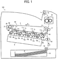
- FIG. 1 is a schematic view of an image forming apparatus 100 according to one or more embodiments of this patent specification.
- the image forming apparatus 100 comprises a tandem color printer that employs four imaging stations, including first through fourth photoconductors 1a, 1b, 1c, and 1d arranged in series, for forming toner images with four different colors: black, magenta, cyan, and yellow. Since the imaging stations are of an identical configuration except for the color of toner used for image formation, features of the photoconductor and its associated imaging equipment described herein apply to all the imaging stations unless otherwise indicated.
- the photoconductor 1 is rotatable in a direction indicated by arrow B, while surrounded by various pieces of imaging equipment, including a discharging device, a charging device 8, a development device 10, and a cleaning device 12, with an exposure device 9 directing a laser beam L to the photoconductive surface, which work in cooperation with each other to form a toner image on the photoconductive surface.
- various pieces of imaging equipment including a discharging device, a charging device 8, a development device 10, and a cleaning device 12, with an exposure device 9 directing a laser beam L to the photoconductive surface, which work in cooperation with each other to form a toner image on the photoconductive surface.
- an intermediate transfer device 60 including an intermediate transfer belt 3 disposed opposite and in contact with the photoconductors 1a, 1b, 1c, and 1d.
- the intermediate transfer belt 3 is entrained about a plurality of belt support rollers, including a driver roller 51 equipped with a suitable rotary actuator and a tension roller 52 loaded with a suitable biasing mechanism, as well as idler rollers 53 and 54, aligned generally parallel to each other.
- a driver roller 51 equipped with a suitable rotary actuator and a tension roller 52 loaded with a suitable biasing mechanism, as well as idler rollers 53 and 54, aligned generally parallel to each other.
- the belt 3 rotates in a direction indicated by arrow A in conjunction with the rollers 52, 53, and 54.
- Four primary transfer rollers 11a, 11b, 11c, and 11d are disposed opposite the photoconductors 1a, 1b, 1c, and 1d, respectively, via the intermediate transfer belt 3 to form four primary transfer nips therebetween, through each of which the toner image is primarily transferred from the photoconductor 1 to the belt 3.
- a secondary transfer roller 17 is disposed opposite the belt support roller 51 via the intermediate transfer belt 3 to form a secondary transfer nip therebetween, through which the toner image is secondarily transferred from the belt 3 to a recording medium such as a sheet of paper P.
- a belt cleaner 20 may be disposed opposite the belt support roller 52 to remove untransferred, residual toner particles that remain on the belt surface after secondary image transfer.
- the intermediate transfer belt 3 comprises a looped belt composed of one or more layers of material.
- the belt material may be selected from polyvinylidene difluoride (PVDF), polycarbonate (PC), and polyimide (PI).
- PVDF polyvinylidene difluoride
- PC polycarbonate
- PI polyimide
- the belt may be formed of a substrate of relatively rigid fluorine rubber, PVDF, or polyimide resin, with a smooth coating of fluorine resin deposited on the substrate.
- the belt cleaner 20 includes a cleaning blade 21 of suitable material, such as urethane, held against the belt 3 to mechanically remove or scrape toner residues from the belt surface.
- a cleaning blade 21 of suitable material such as urethane
- any suitable cleaning device may be used to clean the intermediate transfer belt 3, including, for example, an electrostatic cleaning device that incorporates an electrically conductive fur brush for electrostatically removing toner residues from the belt surface,
- a sheet tray 14 accommodating a stack of recording sheets P.
- a feed roller 15 is disposed at an outlet of the sheet tray 14 to advance the recording sheet P in a direction indicated by arrow C into a sheet conveyance path defined by a suitable sheet conveyance device, including, for example, a movable belt entrained around a plurality of belt support rollers.
- a fixing device 18 is disposed downstream from the secondary transfer nip, which includes, for example, a movable belt entrained around a plurality of belt support rollers to fix the toner image on the recording sheet P.
- the sheet conveyance path terminates in an output unit including a pair of output rollers 19, which outputs the recording sheet P from inside the apparatus body.
- the photoconductor 1 rotates to forward its outer, photoconductive surface to a series of electrophotographic processes, including charging, exposure, development, transfer, and cleaning, in one rotation of the photoconductor 1.
- the photoconductive surface is uniformly charged, for example, to a negative potential by the charging device 8 and subsequently exposed to a modulated laser beam L emitted from the exposure device 9.
- the laser exposure selectively dissipates the charge on the photoconductive surface to form an electrostatic latent image thereon according to image data representing a particular primary color.
- the latent image enters the development device 10, which renders the incoming image visible using toner.
- the toner image thus obtained is forwarded to the primary transfer nip between the intermediate transfer belt 3 and the primary transfer roller 11.
- the primary transfer roller 11 is supplied with a bias voltage of a polarity opposite that of the toner on the photoconductor 1 (for example, a positive bias voltage where the toner assumes a negative charge).
- a bias voltage of a polarity opposite that of the toner on the photoconductor 1 for example, a positive bias voltage where the toner assumes a negative charge.
- Such transfer process occurs sequentially at the four primary transfer nips along the belt travel path, so that toner images of different colors are superimposed one atop another to form a single multicolor image on the surface of the intermediate transfer belt 3.
- the photoconductive surface After primary transfer, the photoconductive surface enters the cleaning device 12 to remove residual toner, and then to the discharging device to remove residual charges for completion of one imaging cycle.
- the intermediate transfer belt 3 forwards the multicolor image to the secondary transfer nip between the belt support roller 51 and the secondary transfer roller 17.
- the feed roller 15 rotates to introduce a recording sheet P from the sheet tray 14 toward the pair of registration rollers 16 being rotated.
- the registration rollers 16 stop rotation to hold the incoming sheet P therebetween, and then advance it in sync with the movement of the intermediate transfer belt 3 to the secondary transfer nip.
- the multicolor image is transferred from the belt 3 to the recording sheet P, with a certain small amount of residual toner particles left on the belt surface.
- the intermediate transfer belt 3 After secondary transfer, the intermediate transfer belt 3 enters the belt cleaner 20, which removes residual toner from the intermediate transfer belt 3. At the same time, the recording sheet P bearing the powder toner image thereon is introduced into the fixing device 20, which fixes the multicolor image in place on the recording sheet P with heat and pressure.
- the recording sheet P is output by the output rollers 19 for stacking outside the apparatus body, which completes one operational cycle of the image forming apparatus 100.
- a belt tracking system 50 is described employed in a multi-roller assembly, including a plurality of rollers about which an endless belt is entrained, which is applicable to the intermediate transfer device 60, the sheet conveyance device, and the fixing device 20 included in the image forming apparatus 100.
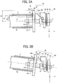
- FIGs. 2A and 2B are cross-sectional views of the belt tracking system 50 according to one embodiment of this patent specification, exemplarily provided in the intermediate transfer device 60 included in the image forming apparatus 100 of FIG. 1 .
- the intermediate transfer belt 3 is entrained about the plurality of generally parallel rollers 51 through 54, of which only one specific roller 52 is visible, for moving in a trans-axial direction perpendicular to an axial direction Z in which the rollers extend parallel to each other.
- the belt tracking system 50 is operatively connected to an axial end of the roller 52 (hereinafter occasionally referred to as a "steering roller") to control the lateral position of the belt 3 by inclining the roller 52 with respect to others of the plurality of generally parallel rollers 51 through 54.
- axial direction refers to a reference, longitudinal direction in which a central, rotational axis of the roller extends in its normal operational position, as indicated by the axis Z in the drawings.
- inward and outward when used in connection with the axial direction, indicates an element moves or otherwise changes in position, size, and/or shape toward and away from, respectively, an axial, longitudinal center of the roller.
- trans-axial direction refers to a given direction perpendicular to the axial direction Z in which the belt is movable, as indicated by the axes X and Y in the drawings. In the present embodiment, for example, the trans-axial directions X and Y are vertical and horizontal, respectively.
- the belt tracking system 50 includes a roller shaft 6 extending outward in the axial direction X from the axial end of the roller 52; a slidable member 41 slidably disposed around the roller shaft 6 to move along the roller shaft 6 as the belt 3 moves laterally outward in the axial direction X; and a positioning flange 30 operatively connected to the axial end of the roller 52 to define a contact surface 30a therealong extending generally perpendicular to the axial direction Z to contact an adjacent edge 3a of the belt 3.
- a position adjuster 40 of which the slidable member 41 forms part, is operatively connected to the axial end of the roller 52 to adjust position of the roller shaft 6 to in turn adjust the lateral position of the belt 3.
- the roller shaft 6 comprises a cylindrical body with a diameter smaller than that of the steering roller 52.
- the roller shaft 6 is coaxially mounted with the roller 52 to integrally rotate with the roller 52.
- the roller shaft 6 penetrates through the positioning flange 30 and the position adjuster 40, in particular, the slidable member 41, such that the positioning flange 30 and the slidable member 41 are movable along the roller shaft 6 generally in the axial direction Z.
- the positioning flange 30 comprises an annular flange supported on the roller shaft 6 loosely, that is, without being fastened to the roller shaft 6 and the roller 52.
- the positioning flange 30 freely rotates around the roller shaft 6 as the belt 3 moves in the trans-axial direction to cause frictional contact between the belt edge 3a and the contact surface 30a.
- the positioning flange 30 freely moves in the axial direction Z along the roller shaft 6 as the belt 3 moves laterally outward in the axial direction Z to exert pressure from the belt edge 3a against the contact surface 30a.
- the contact surface 30a of the positioning flange 30 comprises a generally planar, flat surface with a circular peripheral shape concentric with the rotational axis of the roller 52.
- the contact surface 30a may be configured otherwise as long as the positioning flange 30 properly serves its intended function.
- the contact surface 30a includes any generally planar surface, including a curved surface, an irregular surface, or any combination thereof.
- the peripheral shape of the contact surface 30a includes any closed geometric shape, such as a circle, an ellipse, a rectangle, a polygon, or any combination thereof.
- the contact surface 30a may be shaped and dimensioned such that a distance D1 between a central, rotational axis O of the roller 52 and a periphery M of the contact surface 30a exceeds a sum of a radius D2 of the roller 52 and a thickness T of the belt 3.
- the distance D1 (which is the radius of the circular contact surface 30a in the present case) may be set to a range greater than 8.86 mm, such as approximately 9.00 mm.
- the position adjuster 40 is shown including, in addition to the slidable member 41, a stationary guide member 42 fixed in position adjacent to the roller shaft 6 to define a guide surface 42a therealong.
- the slidable member 41 is co-movably coupled with the roller shaft 6 to define an inclined surface 41a therealong inclined relative to the axial direction Z.
- the slidable member 41 is slidable against the stationary guide member 42 along the inclined surface 41a and the guide surface 42a to cause the roller shaft 6 to move in a direction perpendicular to the axial direction Z upon lateral displacement of the movable belt 3.
- the stationary guide member 42 comprises a stationary structure having an opening defined therein through which the roller shaft 6 is inserted and which accommodates movement of the roller shaft 6 during position adjustment.
- the stationary guide member 42 is positioned axially outward from, and in contact with, the slidable member 41.
- the stationary guide member 42 does not move in the axial direction Z upon displacement of the roller shaft 6 and the slidable member 41.
- the guide surface 42a comprises any surface positioned adjacent to the roller shaft 6 to contact the inclined surface 41a of the slidable member 41.
- the guide surface 42a is shaped into a chamfered edge that extends in the trans-axial direction Y and forms a circular arc in X-Z plane.
- the chamfered guide edge 42a is superior in preventing abrasion on the interfacial surface 41a of the slidable member 41.
- the slidable member 41 comprises an unfixed, movable structure having a through-hole defined therein for passing the roller shaft 6 therethrough.
- the slidable member 41 is positioned axially outward from, and in contact with, the positioning flange 30, so that the slidable member 41 may move along the roller shaft 6 as the positioning flange 30 moves laterally in the axial direction Z, for example, upon lateral movement of the belt 3.
- the inclined surface 41a comprises any inclined surface positioned around the roller shaft 6 to contact the guide surface 42a of the stationary guide member 42.
- the inclined surface 41a slopes toward the roller shaft 6 outward in the axial direction Z.
- the inclined surface 41a is disposed on an upper side of the roller shaft 6 and slopes downward toward the roller shaft 6.
- the inclined surface 41a may be disposed on a lower side of the roller shaft 6 and slopes upward toward the roller shaft 6.
- the inclined surface 41a may be angled at a suitable inclination angle of, for example, approximately 30 degrees relative to the roller shaft 6. Too large an inclination angle would cause an excessive load exerted between the adjoining interfacial surfaces 41a and 42a as the belt edge 3a strikes the positioning flange 30 to press the slidable member 41 against the stationary guide member 42. Conversely, too small an inclination angle would result in a large amount of displacement experienced by the slidable member 41 for inclining the roller 52, which translates into a relatively large space required to accommodate axial displacement of the slidable member 41, adding to the overall size of the belt assembly.
- the inclined surface 41a may be configured as a curved inclined surface that exhibits curvature at least in a trans-axial plane X-Y perpendicular to the axial direction Z.
- Specific examples of the inclined surface 41a include, but are not limited to, a conical surface, a cylindrical surface, a spherical surface, and combinations thereof.
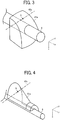
- the inclined surface 41a may be shaped into a cylindrical or spherical surface, as shown in FIG. 3 .
- the inclined surface 41a may be shaped into a conical surface, as shown in FIG. 4 .
- the vertex of the inclined surface 41a may be located coincident with the central axis of the roller shaft 6, which maintains a constant angle or orientation at which the slidable member 41 contacts the stationary guide member 42 during movement of the roller shaft 6.
- the guide surface 42a in the present embodiment is shaped into a chamfered edge extending in the trans-axial direction Y, as indicated by imaginary straight lines in FIGs. 3 and 4 .
- curvature of the inclined surface 41a in the trans-axial plane X-Y allows the interfacial surfaces 41a and 42a of the slidable member 41 and the stationary guide member 42 to contact each other at a specific point Q, rather than along a line or across an area.
- Such arrangement effectively reduces the chances of abrasion spreading over an extended area due to friction between the slidable member 41 and the stationary guide member 42, while allowing for smooth movement of the slidable member 41 along the stationary guide member 42 upon lateral displacement of the movable belt 3, leading to reduced loads on the belt edge 3a.
- the belt 3 rotates or moves in the trans-axial direction Y to in turn cause the steering roller 52 to rotate.
- the contact surface 30a of the positioning flange 30 contacts the belt edge 3a to prevent further displacement of the belt 3, thereby maintaining the belt 3 in its proper lateral position in the axial direction Z.
- the belt edge 3a merely touches or slightly contacts the positioning flange 30 with only a small contact pressure applied from the belt edge 3a to the positioning flange 30, which does not cause the positioning flange 30 to move outward in the axial direction Z.
- the roller shaft 6 remains in its normal position parallel to the axial direction Z, as shown in FIG. 2A .
- the contact pressure from the belt edge 3a to the positioning flange 30 increases to cause the positioning flange 30 to move outward in the axial direction Z against the slidable member 41, so that the slidable member 41 slides downward against the stationary guide member 42 along their interfacial surfaces 41a and 42a.
- the roller shaft 6, which penetrates through, and therefore is co-movable with, the slidable member 41 is forced downward in the vertical, trans-axial direction X perpendicular to the axial direction Z.
- the steering roller 52 having its one axial end vertically displaced and the other axial end held in position, becomes tilted or inclined relative to other rollers included in the multi-roller assembly, as shown in FIG. 2B .
- Such inclination of the roller 52 eventually causes the belt 3 to move laterally inward to resume its proper operational position in the axial direction Z, as described below with additional reference to FIGs. 5A and 5B .
- the belt 3 may experience lateral displacement due to a lack of parallel alignment between the two belt support rollers 52 and 53, the former being exactly parallel to the axial direction Z and the latter being slightly tilted away from the axial direction Z (i.e., having its left end closer to the viewer than its right end in the drawing).
- the belt 3 has its longitudinal axis angled at a clockwise angle ⁇ away from the trans-axial direction Y.
- roller 52 is now tilted away from the axial direction Z at a greater angle than the other roller 53.
- This difference in tilting angle between the belt support rollers 52 and 53 that is, inclination of the roller 52 with respect to the other roller 53, results in a counterclockwise angle ⁇ at which the longitudinal axis of the belt 3 is angled away from the trans-axial direction Y.
- the belt 3 can remain within a desired operational position in the axial direction Z to allow for proper functioning of the imaging equipment.
- the belt tracking system 50 corrects lateral displacement of the belt 3 by tilting the steering roller 52 as the slidable member 41 slides against the stationary guide member 42 along their contact, interfacial surface 41a and 42a where the belt 3 moves laterally outward to the axial end of the roller 52.
- the belt tracking system 50 is shown further including a spacer 7 interposed between the axial end of the roller 52 and the contact surface 30a of the flange 30 to prevent the belt edge 3a from bending away from the positioning flange 30, for example, due to gravity forcing the belt edge 3a downward.
- the spacer 7 comprises an annular cylinder coaxially mounted around the shaft 6 of the roller 52.
- the annular cylindrical spacer 7 has a radius D3 dimensioned smaller than the radius D2 of the roller 52 to create a generally annular gap 31a between the adjacent surfaces of the belt 3 and the spacer 7.
- the spacer 7 may be configured in any suitable regular or irregular geometric shape, including not only cylinders, but also spheres, cubes, and other polygonal prisms, which properly serves its intended function.
- the spacer 7 is spaced apart from the roller 52 to create an axial gap 31b between the adjacent surfaces of the roller 52 and the spacer 7 in the axial direction Z.
- Provision of the axial gap 31b prevents an accidental contact of the roller 52 with the spacer 7 due to dimensional variations over time, which would otherwise result in an irregular pressure exerted from the roller 52 to the positioning flange 30 via the spacer 7.
- Such arrangement ensures inclination of the roller 52 takes place only where the belt edge 3a strikes the positioning flange 30, so that the roller 52 is inclined at a proportional angle of inclination with respect to the other belt-supporting rollers upon lateral displacement of the belt 3 (i.e., the greater the lateral displacement of the belt 3, the greater the angle of inclination of the roller 52, and vice versa), leading to proper adjustment to the lateral position of the belt 52 through inclination of the roller 52.
- FIG. 6 is a side elevational view of the belt tracking system 50 of FIGs. 2A and 2B .
- the position adjuster 40 includes, in addition to the slidable member 41 and the stationary guide member 42, a stationary support 46 fixed in position, and a swivelable member 43 co-movably coupled with the roller shaft 6, while pivoted at a pivot point on the stationary support 46.
- the stationary support 46 comprises a stationary structure having an opening defined therein through which the roller shaft 6 is inserted and which accommodates movement of the roller shaft 6 during position adjustment.
- the stationary support 46 is positioned axially outward from the stationary guide member 42. The stationary support 46 does not move in the axial direction Z where the roller shaft 6 moves or is displaced.
- the swivelable member 43 comprises a composite structure constructed of a hinged plate 43d located axially outward from the stationary support 46; a hinge or pivot 43a provided between the stationary support 46 and the plate 43d around which the plate 43d rotates as the roller shaft 6 moves in a direction perpendicular to the axial direction Z; a bearing 43b disposed around the roller shaft 6 and fixed in rotational position relative to the roller shaft 6; and an elastic bias member 43c connecting the bearing 43b to the hinged plate 43d to exert a biasing force on the roller shaft which elastically biases the roller 52 against the belt 3.
- the elastic bias member 43c for biasing the tension roller 52 may be formed of any suitable elastic material, such as a coil spring, a leaf spring, a rubber band, or the like.
- the position adjuster 40 also includes an elastic retention member 45 connected between the swivelable member 42 and the stationary support 46 to elastically retain the roller shaft 6 in position.
- the elastic retention member 45 comprises a coil spring disposed in tension between the stationary support 46 and the swivelable member 43.
- the elastic retention member 45 may be configured as any suitable elastic material, such as a leaf spring, a rubber band, or the like.
- the swivelable member 43 rotates in a first rotational direction R1, counterclockwise in FIG. 6 , around the pivot 43a.
- the roller shaft 6 which is co-movable with the swivelable member 43, tends to move upward after being displaced downward in the trans-axial direction X.
- Such elastic retention of the roller shaft 6 prevents the slidable member 41 from falling off the stationary guide member 42 due to gravity, leading to continuous contact between the interfacial surfaces 41a and 42a of the slidable member 41 and the stationary guide member 42, which allows for more reliable operation of the belt tracking system 50.
- the belt tracking system 50 includes, in addition to the roller shaft 6 extending outward in the axial direction X from the axial end of the roller 52, and the slidable member 41 slidably disposed around the roller shaft 6 to move along the roller shaft 6 as the belt 3 moves laterally outward in the axial direction X, a rotation restrictor 47 disposed adjacent to the slidable member 41 to restrict rotation of the slidable member 41 around the roller shaft 6.
- the slidable member 41 is occasionally subjected to torque transmitted through friction from the roller shaft 6 rotating as the roller 52 rotates, or from the positioning flange 30, which in the present embodiment is freely rotatable around the roller shaft 6.
- the rotation restrictor 47 secures the slidable member 41 in position against the transmitted torque, such that the slidable member 41 does not rotate around the roller shaft 6 in a trans-axial plane X-Y perpendicular to the axial direction Z.
- Provision of the rotation restrictor 47 protects the slidable member 41 against abrasion and damage due to significant friction at an interfacial surface where the slidable member 41 contacts an adjacent structure, thereby allowing for the reliable, durable belt tracking system 50 that can operate reliably without failure for an extended period of time.
- the inventors have recognized that, although generally successful, the belt tracking system that employs a slidable member slidable against a stationary guide member for tilting a steering roller does not work properly as intended, where the slidable member and the stationary guide member are subjected to significant friction at their interface, which would cause abrasion and damage to the interfacial surfaces, thereby detracting from reliability and durability of the belt tracking system.
- FIGs. 7A and 7B consider an exemplary belt tracking system in which a movable belt 90 is entrained around a steering roller 91.
- the steering roller 91 is equipped with a pair of rotary, slidable members 92 each rotatably mounted to an axial end of the roller 91 to define an inclined, conical interfacial surface 93 therealong to slidably contact a stationary guide member 94.
- the system is designed to correct the lateral position of the belt 90 by tilting the roller 91 as the slidable member 92 slides against the stationary member 94 along the inclined interfacial surface 93 where the belt 90 moves laterally outward to the axial end of the roller 91.
- the belt edge does not contact either of the pair of slidable members 92 on the opposed axial ends of the roller 91.
- the roller 91 remains in its horizontal position with the slidable members 92 symmetrically located with their interfacial surfaces in contact with the respective stationary guide members 94.
- the inclined surface 93 of the rotary, slidable member 92 is subjected to a sliding, frictional contact with the stationary guide member 94 not only where the slidable member 92 moves outward in the axial direction upon lateral displacement of the belt 90, but also where the slidable member 92 rotates as the steering roller 91 rotates.
- Significant friction caused by rotation of the slidable member 92 relative to the stationary guide member 94, if not corrected, would result in accelerated abrasion and damage to their interfacial surfaces, leading to reduced reliability and durability of the belt tracking system.
- provision of the rotation restrictor 47 protects the slidable member 41 and the stationary guide member 42 against abrasion and damage due to significant friction at their interface, thereby allowing for the reliable, durable belt tracking system 50 that can operate reliably without failure for an extended period of time.
- the rotation restrictor 47 is shown fixed in rotational position relative to the roller shaft 6.
- the rotation restrictor 47 may be fixed in rotational position relative to the roller shaft 6 by itself, or alternatively, may be integrally connected with a fixed member fixed in rotational position relative to the roller shaft 6.
- integrally connected refers to direct or indirect connection between the rotation restrictor 47 and the fixed member, which includes any type of affixation or attachment that joins the rotation restrictor 47 and the fixed member together such that they function as a single unit, and does not require the rotation restrictor 47 and the fixed member be made as a single, continuous piece.
- the rotation restrictor 47 is integrally connected with the swivelable member 43, which is co-movably coupled with the roller shaft 6, while pivoted at a pivot point on the stationary support 46, as shown in FIGs. 2A and 2B . More specifically, the rotation restrictor 47 may be integrally connected with the bearing 43b disposed around the roller shaft 6 and fixed in rotational position relative to the roller shaft 6, as shown in FIG. 8 .
- Integral connection of the rotation restrictor 47 with the bearing 43b provides effective restriction on rotation of the slidable member 41 without hindering trans-axial movement of the roller shaft 6 as the elastic bias member 43c extends and compresses to maintain a proper tension in the belt 3. It should be noted that this arrangement is particularly applicable to a configuration in which the belt tracking system 50 is provided to the tension roller 52, as opposed to the others of the plurality of belt support rollers 51, 53, and 54.
- the rotation restrictor 47 may be configured as a flange extending from a fixed member fixed in rotational position relative to the roller shaft 6 to contact the slidable member 41.
- the rotation restrictor may be configured as a flange extending from the slidable member 41 to contact a fixed member fixed in rotational position relative to the roller shaft 6. Specific examples of the rotation restrictor 47 are shown with reference to FIGs. 9 through 12 .
- the rotation restrictor 47 may be configured as a flange extending from the bearing 43b to contact the slidable member 41.
- the flange 47 may have a generally U-shaped cross section in X-Y plane to fit along a bottom and two opposed sides of the slidable member 41, as shown in FIG. 9 .
- the flange 47 may have a generally U-shaped cross section in X-Y plane to fit along a top, bottom and one side of the slidable member 41, as shown in FIG. 10 .
- the rotation restrictor 47 may be configured as a pair of flanges extending from the bearing 43b to contact the slidable member 41.
- each of the pair of flanges 47 may have a generally L-shaped cross section in X-Y plane to fit along two adjoining sides of the slidable member 41, as shown in FIG. 11 .
- the rotation restrictor 47 may be configured as a flange extending from the slidable member 41 to contact the bearing 43b, as shown in FIG. 12 .
- the flange 47 may pass through a slit 48 provided in the bearing 43b, as shown in FIGs. 13A and 13B .
- the rotation restrictor 47 effectively resists torque that forces the slidable member 41 around the roller shaft 6 in a rotational direction R3 in X-Y plane, while allowing occasional movement of the slidable member 41 in X-Z plane, for example, where the belt edge 3a exerts pressure against the slidable member 41 via the positioning flange 30 in the axial direction Z.
- the rotation restrictor 47 is depicted as being attached to the bearing 43b, the fixed member with which the rotation restrictor 47 is integrally connected is not limited to the bearing 43b, but includes any portion of the belt tracking system 50 that is fixed in rotational position relative to the roller shaft 6.
- the rotation restrictor 47 may be integrally connected with other portions of the swivelable member 43 than the bearing 43b. Further, in a configuration in which the positioning flange 30 does not rotate around the roller shaft 6, the rotation restrictor 47 may be integrally connected with the positioning flange 30. Furthermore, the rotation restrictor 47 may be integrally connected with the stationary guide member 42 or the stationary support 46, instead of the swivelable member, particularly in a configuration in which the belt tracking system 50 is provided to one of the plurality of belt support rollers other than the tension roller 52.
- FIG. 14 is a schematic view of the multi-roller assembly employing the belt tracking system 50.
- the movable belt 3 is entrained about at least three generally parallel rollers 51 through 54, including the roller 52 to which the belt tracking system 50 is provided, such that the axial end of the roller 52 is movable in an elliptical path E whose foci coincide with adjacent two of the at least three generally parallel rollers, which are, in this case, the rollers 51 and 53, where the endless belt 3 has a generally constant circumferential length.
- the guide surface 42a extends at an oblique angle 0 with respect to a common tangential line F between the elliptical path E and the axial end of the roller 52 where the roller 52 extends parallel to the adjacent rollers 51 and 53.
- the oblique angle ⁇ may be any angle other than 90°, such as, for example, an angle in a range from approximately 77° to approximately 82°.
- the roller 52 As the roller 52 is inclined generally downward in the vertical trans-axial direction X, the axial end of the roller 52 is displaced to a first displacement position 52B closer to the downstream adjacent roller 53. At this point, the slidable member 41 is displaced to a corresponding displacement position 41B to contact the stationary guide member 42 at a point of contact QB.
- the axial end of the roller 52 is displaced to a second displacement position 52C closer to the upstream adjacent roller 51.
- the slidable member 41 is displaced to a corresponding displacement position 41C to contact the stationary guide member 42 at a point of contact QC.
- the slidable member 41 and the stationary guide member 42 contact each other at different points of contact QA, QB, and QC as the slidable member 41 slides against the stationary guide member 42 along the inclined surface 41a and the guide surface 42a. Varying the point of contact Q between the slidable member 41 and the stationary guide member 42 prevents concentration of loads on a particular point across the guide surface 42a, which would otherwise result in accelerated abrasion and damage to the stationary guide member 42.
- an endless belt 80 is entrained around two rollers 81 and 82.
- the roller 81 is provided with a slidable member 83 slidable against a stationary guide member 84 extending at a right angle with respect to a common tangential line F between an imaginary circular path in which the roller end is movable, and the axial end of the roller 81 where the roller 81 extends parallel to the adjacent roller 82.
- the axial end of the roller 81 is displaced to a displacement position 81B.
- the slidable member 83 which is displaced to a corresponding displacement position 83B, contacts the stationary guide member 84 at the same point of contact Q as that observed before inclination of the roller 81.
- the slidable member 83 and the stationary guide member 84 contact each other at the fixed point of contact Q as the slidable member 83 slides against the stationary guide member 84 along their interfacial surfaces. Failure to vary the point of contact Q between the slidable member 83 and the stationary guide member 84 results in concentration of loads on a particular point across the guide surface, leading to accelerated abrasion and damage to the stationary guide member 84.
- the belt tracking system 50 may be configured otherwise than that described herein.
- the belt tracking system 50 may be operatively connected to each of two axial ends of the roller.
- the belt tracking system 50 may be provided to more than one of the plurality of generally parallel rollers about which the movable belt is entrained.
- the belt tracking system 50 may be employed in any type of imaging equipment incorporating a multi-roller belt-support assembly, such as an intermediate transfer unit for transferring a toner image from a photoconductive surface, a conveyance unit for conveying a recording medium, and a fixing unit for fixing a toner image in place on a recording medium, included in the image forming apparatus, such as a photocopier, facsimile machine, printer, plotter, or multifunctional machine incorporating several of these features.
- a multi-roller belt-support assembly such as an intermediate transfer unit for transferring a toner image from a photoconductive surface, a conveyance unit for conveying a recording medium, and a fixing unit for fixing a toner image in place on a recording medium, included in the image forming apparatus, such as a photocopier, facsimile machine, printer, plotter, or multifunctional machine incorporating several of these features.
Description
- The present invention relates to a belt tracking system, a multi-roller assembly and an image forming apparatus employing the same, and more particularly, to a belt tracking system for controlling the lateral position of a movable belt entrained about a plurality of rollers, and a multi-roller assembly and an image forming apparatus employing the belt tracking system.
- Image forming apparatuses employ various types of movable imaging belts, such as an intermediate transfer belt, a media conveyance belt, and a fixing belt, each of which is entrained about a plurality of generally parallel rollers for moving in a trans-axial direction perpendicular to an axial direction in which the rollers extend parallel to each other.
- One problem associated with a multi-roller belt-support assembly is that the movable belt occasionally walks or moves laterally in the axial direction due to a lack of parallel alignment between the belt support rollers, which results, for example, from wear and tear of equipment used to rotate the belt support rollers. Such lateral displacement of the belt, if not corrected, would cause breakage or failure of the imaging process where the belt reaches the axial end of the roller and eventually slips off the belt-support assembly.
- To address this problem, several techniques have been proposed which employ a belt tracking system connected to an axial end of the belt support roller to control the lateral position of the movable belt.
- For example, there is known a belt tracking system in which a movable belt is entrained around a steering roller. The steering roller is equipped with a pair of rotary, slidable members each rotatably mounted to an axial end of the roller to define an inclined, conical interfacial surface therealong to slidably contact a stationary guide member. The system is designed to correct lateral displacement of the belt by tilting the steering roller as the slidable member slides against the stationary member along the inclined interfacial surface where the belt moves laterally outward to the axial end of the roller.
- The inventors have recognized that, although generally successful, the belt tracking system that employs a slidable member slidable against a stationary guide member for tilting a steering roller does not work properly as intended, where the slidable member and the stationary guide member are subjected to significant friction at their interface, which would cause abrasion and damage to the interfacial surfaces, thereby detracting from reliability and durability of the belt tracking system.
- With reference to
FIGs. 7A and 7B , consider an exemplary belt tracking system in which amovable belt 90 is entrained around asteering roller 91. Thesteering roller 91 is equipped with a pair of rotary,slidable members 92 each rotatably mounted to an axial end of theroller 91 to define an inclined, conicalinterfacial surface 93 therealong to slidably contact astationary guide member 94. The system is designed to correct the lateral position of thebelt 90 by tilting theroller 91 as theslidable member 92 slides against thestationary member 94 along the inclinedinterfacial surface 93 where thebelt 90 moves laterally outward to the axial end of theroller 91. - Specifically, as shown in
FIG. 7A , where thebelt 90 is in its neutral, proper operational position, the belt edge does not contact either of the pair ofslidable members 92 on the opposed axial ends of theroller 91. At this point, theroller 91 remains in its horizontal position with theslidable members 92 symmetrically located with their interfacial surfaces in contact with the respectivestationary guide members 94. - As shown in
FIG. 7B , where thebelt 90 is displaced laterally (in this case, to the right side of the drawing), the belt edge contacts and presses against theslidable member 92 on one axial end of theroller 91. As a result, theslidable member 92 on that axial end slides downward against thestationary member 94, whereas theslidable member 92 on the other axial end moves upward, thereby tilting theroller 91 to counteract the lateral displacement of thebelt 90. - In the belt tracking system, the
inclined surface 93 of the rotary,slidable member 92 is subjected to a sliding, frictional contact with thestationary guide member 94 not only where theslidable member 92 moves outward in the axial direction upon lateral displacement of thebelt 90, but also where theslidable member 92 rotates as thesteering roller 91 rotates. Significant friction caused by rotation of theslidable member 92 relative to thestationary guide member 94, if not corrected, would result in accelerated abrasion and damage to their interfacial surfaces, leading to reduced reliability and durability of the belt tracking system. - Exemplary aspects of the present invention are put forward in view of the above-described circumstances, and provide a novel belt tracking system for controlling the lateral position of a movable belt entrained about a plurality of generally parallel rollers for moving in a trans-axial direction perpendicular to an axial direction in which the rollers extend parallel to each other.
- The invention is defined by the independent claim 1.
- The preferred embodiments are defined in the dependent claims.
- Provision of the rotation restrictor protects the slidable member against abrasion and damage due to significant friction at an interfacial surface where the slidable member contacts an adjacent structure, thereby allowing for the reliable, durable belt tracking system that can operate reliably without failure for an extended period of time.
- Other exemplary aspects of the present invention are put forward in view of the above-described circumstances, and provide a multi-roller assembly employing the belt tracking system.
- A more complete appreciation of the disclosure and many of the attendant advantages thereof will be readily obtained as the same becomes better understood by reference to the following detailed description when considered in connection with the accompanying drawings, wherein:
-
FIG. 1 is a schematic view of an image forming apparatus according to one or more embodiments of this patent specification; -
FIGs. 2A and 2B are cross-sectional views of the belt tracking system according to one embodiment of this patent specification; -
FIG. 3 is a perspective view of an example of a slidable member included in the belt tracking system ofFIGs. 2A and 2B ; -
FIG. 4 is a perspective view of another example of the slidable member; -
FIGs. 5A and 5B are schematic plan views of a movable belt entrained around multiple rollers inclined relative to each other; -
FIG. 6 is a side elevational view of the belt tracking system ofFIGs. 2A and 2B ; -
FIGs. 7A and 7B are schematic elevational views of an exemplary belt tracking system; -
FIG. 8 is a cross-sectional view of the belt tracking system according to another embodiment of this patent specification; -
FIG. 9 is a schematic view of an example of a rotation restrictor included in the belt tracking system ofFIGs. 2A and 2B ; -
FIG. 10 is a schematic view of another example of the rotation restrictor; -
FIG. 11 is a schematic view of still another example of the rotation restrictor; -
FIG. 12 is a schematic view of yet still another example of the rotation restrictor; -
FIGs. 13A and 13B are cross-sectional and side elevational views of the belt tacking system according to another embodiment of this patent specification; -
FIG. 14 is a schematic view of a multi-roller assembly employing the belt tracking system ofFIGs. 2A and 2B ; and -
FIG. 15 is a schematic view of an exemplary belt tracking system. - In describing exemplary embodiments illustrated in the drawings, specific terminology is employed for the sake of clarity. However, the disclosure of this patent specification is not intended to be limited to the specific terminology so selected, and it is to be understood that each specific element includes all technical equivalents that operate in a similar manner and achieve a similar result.
- Referring now to the drawings, wherein like reference numerals designate identical or corresponding parts throughout the several views, exemplary embodiments of the present patent application are described.
-
FIG. 1 is a schematic view of animage forming apparatus 100 according to one or more embodiments of this patent specification. - As shown in
FIG. 1 , theimage forming apparatus 100 comprises a tandem color printer that employs four imaging stations, including first throughfourth photoconductors - In each imaging station, the photoconductor 1 is rotatable in a direction indicated by arrow B, while surrounded by various pieces of imaging equipment, including a discharging device, a
charging device 8, a development device 10, and a cleaning device 12, with anexposure device 9 directing a laser beam L to the photoconductive surface, which work in cooperation with each other to form a toner image on the photoconductive surface. - Also included in the
image forming apparatus 100 is anintermediate transfer device 60 including anintermediate transfer belt 3 disposed opposite and in contact with thephotoconductors intermediate transfer belt 3 is entrained about a plurality of belt support rollers, including adriver roller 51 equipped with a suitable rotary actuator and atension roller 52 loaded with a suitable biasing mechanism, as well asidler rollers driver roller 51 rotates, thebelt 3 rotates in a direction indicated by arrow A in conjunction with therollers - Four
primary transfer rollers photoconductors intermediate transfer belt 3 to form four primary transfer nips therebetween, through each of which the toner image is primarily transferred from the photoconductor 1 to thebelt 3. Asecondary transfer roller 17 is disposed opposite thebelt support roller 51 via theintermediate transfer belt 3 to form a secondary transfer nip therebetween, through which the toner image is secondarily transferred from thebelt 3 to a recording medium such as a sheet of paper P. - Additionally, a
belt cleaner 20 may be disposed opposite thebelt support roller 52 to remove untransferred, residual toner particles that remain on the belt surface after secondary image transfer. - In the present embodiment, the
intermediate transfer belt 3 comprises a looped belt composed of one or more layers of material. In the case of a mono-layered belt, the belt material may be selected from polyvinylidene difluoride (PVDF), polycarbonate (PC), and polyimide (PI). In the case of a poly-layered belt, the belt may be formed of a substrate of relatively rigid fluorine rubber, PVDF, or polyimide resin, with a smooth coating of fluorine resin deposited on the substrate. - In the present embodiment, the
belt cleaner 20 includes acleaning blade 21 of suitable material, such as urethane, held against thebelt 3 to mechanically remove or scrape toner residues from the belt surface. Alternatively, instead of or in combination with a cleaning blade, any suitable cleaning device may be used to clean theintermediate transfer belt 3, including, for example, an electrostatic cleaning device that incorporates an electrically conductive fur brush for electrostatically removing toner residues from the belt surface, - At the bottom of the
apparatus 100 lies asheet tray 14 accommodating a stack of recording sheets P.A feed roller 15 is disposed at an outlet of thesheet tray 14 to advance the recording sheet P in a direction indicated by arrow C into a sheet conveyance path defined by a suitable sheet conveyance device, including, for example, a movable belt entrained around a plurality of belt support rollers. - Along the sheet conveyance path is a pair of
registration roller 16 for introducing the recording sheet P into the secondary transfer nip. A fixingdevice 18 is disposed downstream from the secondary transfer nip, which includes, for example, a movable belt entrained around a plurality of belt support rollers to fix the toner image on the recording sheet P. The sheet conveyance path terminates in an output unit including a pair ofoutput rollers 19, which outputs the recording sheet P from inside the apparatus body. - During operation, in each imaging station, the photoconductor 1 rotates to forward its outer, photoconductive surface to a series of electrophotographic processes, including charging, exposure, development, transfer, and cleaning, in one rotation of the photoconductor 1.
- First, after being exposed to light radiation from the discharging device, which removes residual electrical charges for initialization, the photoconductive surface is uniformly charged, for example, to a negative potential by the charging
device 8 and subsequently exposed to a modulated laser beam L emitted from theexposure device 9. The laser exposure selectively dissipates the charge on the photoconductive surface to form an electrostatic latent image thereon according to image data representing a particular primary color. Then, the latent image enters the development device 10, which renders the incoming image visible using toner. The toner image thus obtained is forwarded to the primary transfer nip between theintermediate transfer belt 3 and the primary transfer roller 11. - At the primary transfer nip, the primary transfer roller 11 is supplied with a bias voltage of a polarity opposite that of the toner on the photoconductor 1 (for example, a positive bias voltage where the toner assumes a negative charge). This electrostatically transfers the toner image from the photoconductive surface to an outer surface of the
belt 3, with a certain small amount of residual toner particles left on the photoconductive surface. Such transfer process occurs sequentially at the four primary transfer nips along the belt travel path, so that toner images of different colors are superimposed one atop another to form a single multicolor image on the surface of theintermediate transfer belt 3. - After primary transfer, the photoconductive surface enters the cleaning device 12 to remove residual toner, and then to the discharging device to remove residual charges for completion of one imaging cycle. At the same time, the
intermediate transfer belt 3 forwards the multicolor image to the secondary transfer nip between thebelt support roller 51 and thesecondary transfer roller 17. - Meanwhile, in the sheet conveyance path, the
feed roller 15 rotates to introduce a recording sheet P from thesheet tray 14 toward the pair ofregistration rollers 16 being rotated. Upon receiving the fed sheet P, theregistration rollers 16 stop rotation to hold the incoming sheet P therebetween, and then advance it in sync with the movement of theintermediate transfer belt 3 to the secondary transfer nip. At the secondary transfer nip, the multicolor image is transferred from thebelt 3 to the recording sheet P, with a certain small amount of residual toner particles left on the belt surface. - After secondary transfer, the
intermediate transfer belt 3 enters thebelt cleaner 20, which removes residual toner from theintermediate transfer belt 3. At the same time, the recording sheet P bearing the powder toner image thereon is introduced into the fixingdevice 20, which fixes the multicolor image in place on the recording sheet P with heat and pressure. - Thereafter, the recording sheet P is output by the
output rollers 19 for stacking outside the apparatus body, which completes one operational cycle of theimage forming apparatus 100. - A description is now given of specific features of the
image forming apparatus 100 according to one or more embodiments of this patent specification. In each of these embodiments, abelt tracking system 50 is described employed in a multi-roller assembly, including a plurality of rollers about which an endless belt is entrained, which is applicable to theintermediate transfer device 60, the sheet conveyance device, and the fixingdevice 20 included in theimage forming apparatus 100. -
FIGs. 2A and 2B are cross-sectional views of thebelt tracking system 50 according to one embodiment of this patent specification, exemplarily provided in theintermediate transfer device 60 included in theimage forming apparatus 100 ofFIG. 1 . - As shown in
FIGs. 2A and 2B , theintermediate transfer belt 3 is entrained about the plurality of generallyparallel rollers 51 through 54, of which only onespecific roller 52 is visible, for moving in a trans-axial direction perpendicular to an axial direction Z in which the rollers extend parallel to each other. Thebelt tracking system 50 is operatively connected to an axial end of the roller 52 (hereinafter occasionally referred to as a "steering roller") to control the lateral position of thebelt 3 by inclining theroller 52 with respect to others of the plurality of generallyparallel rollers 51 through 54. - As used herein, the term "axial direction" refers to a reference, longitudinal direction in which a central, rotational axis of the roller extends in its normal operational position, as indicated by the axis Z in the drawings. The terms "inward" and "outward", when used in connection with the axial direction, indicates an element moves or otherwise changes in position, size, and/or shape toward and away from, respectively, an axial, longitudinal center of the roller. The term "trans-axial direction" refers to a given direction perpendicular to the axial direction Z in which the belt is movable, as indicated by the axes X and Y in the drawings. In the present embodiment, for example, the trans-axial directions X and Y are vertical and horizontal, respectively.
- The
belt tracking system 50 includes aroller shaft 6 extending outward in the axial direction X from the axial end of theroller 52; aslidable member 41 slidably disposed around theroller shaft 6 to move along theroller shaft 6 as thebelt 3 moves laterally outward in the axial direction X; and apositioning flange 30 operatively connected to the axial end of theroller 52 to define acontact surface 30a therealong extending generally perpendicular to the axial direction Z to contact anadjacent edge 3a of thebelt 3. Aposition adjuster 40, of which theslidable member 41 forms part, is operatively connected to the axial end of theroller 52 to adjust position of theroller shaft 6 to in turn adjust the lateral position of thebelt 3. - Specifically, in the present embodiment, the
roller shaft 6 comprises a cylindrical body with a diameter smaller than that of the steeringroller 52. Theroller shaft 6 is coaxially mounted with theroller 52 to integrally rotate with theroller 52. Theroller shaft 6 penetrates through thepositioning flange 30 and theposition adjuster 40, in particular, theslidable member 41, such that thepositioning flange 30 and theslidable member 41 are movable along theroller shaft 6 generally in the axial direction Z. - The
positioning flange 30 comprises an annular flange supported on theroller shaft 6 loosely, that is, without being fastened to theroller shaft 6 and theroller 52. Thus, thepositioning flange 30 freely rotates around theroller shaft 6 as thebelt 3 moves in the trans-axial direction to cause frictional contact between thebelt edge 3a and thecontact surface 30a. Also, thepositioning flange 30 freely moves in the axial direction Z along theroller shaft 6 as thebelt 3 moves laterally outward in the axial direction Z to exert pressure from thebelt edge 3a against thecontact surface 30a. - Compared to holding the flange stationary in position, allowing free rotation of the
positioning flange 30 together with thebelt 3 reduces load due to friction between thebelt edge 3a and thecontact surface 30a, thereby preventing damage to thebelt 3 and abrasion on thecontact surface 30a. - The
contact surface 30a of thepositioning flange 30 comprises a generally planar, flat surface with a circular peripheral shape concentric with the rotational axis of theroller 52. Alternatively, instead of a flat circular configuration, thecontact surface 30a may be configured otherwise as long as thepositioning flange 30 properly serves its intended function. Thus, thecontact surface 30a includes any generally planar surface, including a curved surface, an irregular surface, or any combination thereof. Further, the peripheral shape of thecontact surface 30a includes any closed geometric shape, such as a circle, an ellipse, a rectangle, a polygon, or any combination thereof. - The
contact surface 30a may be shaped and dimensioned such that a distance D1 between a central, rotational axis O of theroller 52 and a periphery M of thecontact surface 30a exceeds a sum of a radius D2 of theroller 52 and a thickness T of thebelt 3. - For example, where the assembly is constructed with a roller radius D2 of 8.78 mm and a belt thickness T of 80 µm, the distance D1 (which is the radius of the
circular contact surface 30a in the present case) may be set to a range greater than 8.86 mm, such as approximately 9.00 mm. - Setting the distance D1 to an appropriate range ensures the
positioning flange 30 properly guides thebelt edge 3a to thecontact surface 30a without causing undue interference with surrounding structures. Such arrangement effectively prevents substantial displacement or walk of the belt, in which the belt reaches the axial end of the roller and eventually slips off the belt support roller. - With continued reference to
FIGs. 2A and 2B , theposition adjuster 40 is shown including, in addition to theslidable member 41, astationary guide member 42 fixed in position adjacent to theroller shaft 6 to define aguide surface 42a therealong. Theslidable member 41 is co-movably coupled with theroller shaft 6 to define aninclined surface 41a therealong inclined relative to the axial direction Z. Theslidable member 41 is slidable against thestationary guide member 42 along theinclined surface 41a and theguide surface 42a to cause theroller shaft 6 to move in a direction perpendicular to the axial direction Z upon lateral displacement of themovable belt 3. - Specifically, in the present embodiment, the
stationary guide member 42 comprises a stationary structure having an opening defined therein through which theroller shaft 6 is inserted and which accommodates movement of theroller shaft 6 during position adjustment. Thestationary guide member 42 is positioned axially outward from, and in contact with, theslidable member 41. Thestationary guide member 42 does not move in the axial direction Z upon displacement of theroller shaft 6 and theslidable member 41. - The
guide surface 42a comprises any surface positioned adjacent to theroller shaft 6 to contact theinclined surface 41a of theslidable member 41. For example, in the present embodiment, theguide surface 42a is shaped into a chamfered edge that extends in the trans-axial direction Y and forms a circular arc in X-Z plane. Compared to a sharp-cornered edge, the chamferedguide edge 42a is superior in preventing abrasion on theinterfacial surface 41a of theslidable member 41. - The
slidable member 41 comprises an unfixed, movable structure having a through-hole defined therein for passing theroller shaft 6 therethrough. Theslidable member 41 is positioned axially outward from, and in contact with, thepositioning flange 30, so that theslidable member 41 may move along theroller shaft 6 as thepositioning flange 30 moves laterally in the axial direction Z, for example, upon lateral movement of thebelt 3. - The
inclined surface 41a comprises any inclined surface positioned around theroller shaft 6 to contact theguide surface 42a of thestationary guide member 42. Theinclined surface 41a slopes toward theroller shaft 6 outward in the axial direction Z. In the present embodiment, for example, theinclined surface 41a is disposed on an upper side of theroller shaft 6 and slopes downward toward theroller shaft 6. Alternatively, instead, theinclined surface 41a may be disposed on a lower side of theroller shaft 6 and slopes upward toward theroller shaft 6. - The
inclined surface 41a may be angled at a suitable inclination angle of, for example, approximately 30 degrees relative to theroller shaft 6. Too large an inclination angle would cause an excessive load exerted between the adjoininginterfacial surfaces belt edge 3a strikes thepositioning flange 30 to press theslidable member 41 against thestationary guide member 42. Conversely, too small an inclination angle would result in a large amount of displacement experienced by theslidable member 41 for inclining theroller 52, which translates into a relatively large space required to accommodate axial displacement of theslidable member 41, adding to the overall size of the belt assembly. - The
inclined surface 41a may be configured as a curved inclined surface that exhibits curvature at least in a trans-axial plane X-Y perpendicular to the axial direction Z. Specific examples of theinclined surface 41a include, but are not limited to, a conical surface, a cylindrical surface, a spherical surface, and combinations thereof. - For example, the
inclined surface 41a may be shaped into a cylindrical or spherical surface, as shown inFIG. 3 . Alternatively, instead, theinclined surface 41a may be shaped into a conical surface, as shown inFIG. 4 . In the case of the conical configuration, the vertex of theinclined surface 41a may be located coincident with the central axis of theroller shaft 6, which maintains a constant angle or orientation at which theslidable member 41 contacts thestationary guide member 42 during movement of theroller shaft 6. - As mentioned earlier, the
guide surface 42a in the present embodiment is shaped into a chamfered edge extending in the trans-axial direction Y, as indicated by imaginary straight lines inFIGs. 3 and 4 . In such cases, curvature of theinclined surface 41a in the trans-axial plane X-Y allows theinterfacial surfaces slidable member 41 and thestationary guide member 42 to contact each other at a specific point Q, rather than along a line or across an area. - Such arrangement effectively reduces the chances of abrasion spreading over an extended area due to friction between the
slidable member 41 and thestationary guide member 42, while allowing for smooth movement of theslidable member 41 along thestationary guide member 42 upon lateral displacement of themovable belt 3, leading to reduced loads on thebelt edge 3a. - With reference to
FIGs. 2A and 2B , a description is given of an operation of thebelt tracking system 50 correcting the lateral position of themovable belt 3. - During operation, as the
driver roller 51 rotates, thebelt 3 rotates or moves in the trans-axial direction Y to in turn cause the steeringroller 52 to rotate. As thebelt 3 moves laterally outward in the axial direction Z along theroller 52, for example, due to a lack of parallel alignment between the belt-supporting rollers, thecontact surface 30a of thepositioning flange 30 contacts thebelt edge 3a to prevent further displacement of thebelt 3, thereby maintaining thebelt 3 in its proper lateral position in the axial direction Z. - Where the
belt 3 is in its proper operational position, thebelt edge 3a merely touches or slightly contacts thepositioning flange 30 with only a small contact pressure applied from thebelt edge 3a to thepositioning flange 30, which does not cause thepositioning flange 30 to move outward in the axial direction Z. At this point, theroller shaft 6 remains in its normal position parallel to the axial direction Z, as shown inFIG. 2A . - Where the
belt 3 moves laterally outward in the axial direction Z, the contact pressure from thebelt edge 3a to thepositioning flange 30 increases to cause thepositioning flange 30 to move outward in the axial direction Z against theslidable member 41, so that theslidable member 41 slides downward against thestationary guide member 42 along theirinterfacial surfaces slidable member 41 thus descending, theroller shaft 6, which penetrates through, and therefore is co-movable with, theslidable member 41, is forced downward in the vertical, trans-axial direction X perpendicular to the axial direction Z. - As a result, the steering
roller 52, having its one axial end vertically displaced and the other axial end held in position, becomes tilted or inclined relative to other rollers included in the multi-roller assembly, as shown inFIG. 2B . Such inclination of theroller 52 eventually causes thebelt 3 to move laterally inward to resume its proper operational position in the axial direction Z, as described below with additional reference toFIGs. 5A and 5B . - As shown in
FIG. 5A , thebelt 3 may experience lateral displacement due to a lack of parallel alignment between the twobelt support rollers belt 3 has its longitudinal axis angled at a clockwise angle α away from the trans-axial direction Y. - At this point, where the
belt 3 travels a distance L in the trans-axial direction Y, a given point on the belt surface moves by an amount L∗tan α to one side (i.e., the right side in the drawing) in the axial direction Z. - As shown in
FIG. 5B , as the lateral displacement of thebelt 3 shifts the axial end of theroller 52 in the trans-axial direction X perpendicular to the axial direction Z, theroller 52 becomes angled away from parallel alignment (i.e., having its left end closer to the viewer than its right end in the drawing) whereas theroller 53 remains in its original angular position. - Note that the
roller 52 is now tilted away from the axial direction Z at a greater angle than theother roller 53. This difference in tilting angle between thebelt support rollers roller 52 with respect to theother roller 53, results in a counterclockwise angle β at which the longitudinal axis of thebelt 3 is angled away from the trans-axial direction Y. - At this point, as the
belt 3 travels a distance L in the trans-axial direction Y, a given point on the belt surface moves by an amount L∗tan β to the side opposite that to which belt displacement took place in the axial direction Z before tilting of theroller 52. - As the amount of displacement L∗tan α experienced by the
belt 3 to one lateral side is cancelled out by the amount of displacement L∗tan β to the other lateral side, thebelt 3 can remain within a desired operational position in the axial direction Z to allow for proper functioning of the imaging equipment. - Thus, the
belt tracking system 50 corrects lateral displacement of thebelt 3 by tilting the steeringroller 52 as theslidable member 41 slides against thestationary guide member 42 along their contact,interfacial surface belt 3 moves laterally outward to the axial end of theroller 52. - With continued reference to
FIGs. 2A and 2B , thebelt tracking system 50 is shown further including aspacer 7 interposed between the axial end of theroller 52 and thecontact surface 30a of theflange 30 to prevent thebelt edge 3a from bending away from thepositioning flange 30, for example, due to gravity forcing thebelt edge 3a downward. - Specifically, in the present embodiment, the
spacer 7 comprises an annular cylinder coaxially mounted around theshaft 6 of theroller 52. The annularcylindrical spacer 7 has a radius D3 dimensioned smaller than the radius D2 of theroller 52 to create a generallyannular gap 31a between the adjacent surfaces of thebelt 3 and thespacer 7. It is to be noted that thespacer 7 may be configured in any suitable regular or irregular geometric shape, including not only cylinders, but also spheres, cubes, and other polygonal prisms, which properly serves its intended function. - More specifically, in the present embodiment, the
spacer 7 is spaced apart from theroller 52 to create anaxial gap 31b between the adjacent surfaces of theroller 52 and thespacer 7 in the axial direction Z. - Provision of the
axial gap 31b prevents an accidental contact of theroller 52 with thespacer 7 due to dimensional variations over time, which would otherwise result in an irregular pressure exerted from theroller 52 to thepositioning flange 30 via thespacer 7. Such arrangement ensures inclination of theroller 52 takes place only where thebelt edge 3a strikes thepositioning flange 30, so that theroller 52 is inclined at a proportional angle of inclination with respect to the other belt-supporting rollers upon lateral displacement of the belt 3 (i.e., the greater the lateral displacement of thebelt 3, the greater the angle of inclination of theroller 52, and vice versa), leading to proper adjustment to the lateral position of thebelt 52 through inclination of theroller 52. -
FIG. 6 is a side elevational view of thebelt tracking system 50 ofFIGs. 2A and 2B . - As shown in
FIG. 6 , theposition adjuster 40 includes, in addition to theslidable member 41 and thestationary guide member 42, astationary support 46 fixed in position, and aswivelable member 43 co-movably coupled with theroller shaft 6, while pivoted at a pivot point on thestationary support 46. - In the present embodiment, the
stationary support 46 comprises a stationary structure having an opening defined therein through which theroller shaft 6 is inserted and which accommodates movement of theroller shaft 6 during position adjustment. Thestationary support 46 is positioned axially outward from thestationary guide member 42. Thestationary support 46 does not move in the axial direction Z where theroller shaft 6 moves or is displaced. - The swivelable
member 43 comprises a composite structure constructed of a hingedplate 43d located axially outward from thestationary support 46; a hinge orpivot 43a provided between thestationary support 46 and theplate 43d around which theplate 43d rotates as theroller shaft 6 moves in a direction perpendicular to the axial direction Z; abearing 43b disposed around theroller shaft 6 and fixed in rotational position relative to theroller shaft 6; and anelastic bias member 43c connecting the bearing 43b to the hingedplate 43d to exert a biasing force on the roller shaft which elastically biases theroller 52 against thebelt 3. - Provision of the swivelable
member 43 with theelastic bias member 43c allows theroller 52 to function as a tension roller that forces thebelt 3 away from the other belt-supporting rollers to maintain tension in thebelt 3. Theelastic bias member 43c for biasing thetension roller 52 may be formed of any suitable elastic material, such as a coil spring, a leaf spring, a rubber band, or the like. - Additionally, in the present embodiment, the
position adjuster 40 also includes anelastic retention member 45 connected between theswivelable member 42 and thestationary support 46 to elastically retain theroller shaft 6 in position. Theelastic retention member 45 comprises a coil spring disposed in tension between thestationary support 46 and the swivelablemember 43. Alternatively, instead of a coil spring, theelastic retention member 45 may be configured as any suitable elastic material, such as a leaf spring, a rubber band, or the like. - During operation, where the
roller shaft 6 moves downward in the vertical, trans-axial direction X for correcting the lateral position of thebelt 3, the swivelablemember 43 rotates in a first rotational direction R1, counterclockwise inFIG. 6 , around thepivot 43a. - As rotation of the swivelable
member 43 causes theelastic retention member 45 to stretch, the resultant elastic force, which opposes the change in length of theelastic retention member 45, causes theswivelable member 43 to rotate backward in a second rotational direction R2, clockwise inFIG. 6 , around thepivot 43a. - Thus, with the
elastic retention member 45 connected between theswivelable member 43 and thestationary support 46, theroller shaft 6, which is co-movable with the swivelablemember 43, tends to move upward after being displaced downward in the trans-axial direction X. Such elastic retention of theroller shaft 6 prevents theslidable member 41 from falling off thestationary guide member 42 due to gravity, leading to continuous contact between theinterfacial surfaces slidable member 41 and thestationary guide member 42, which allows for more reliable operation of thebelt tracking system 50. - Referring back to
FIGs. 2A and 2B , a description is now given of specific features of thebelt tracking system 50 according to several embodiments of this patent specification. - As shown in
FIGs. 2A and 2B , thebelt tracking system 50 includes, in addition to theroller shaft 6 extending outward in the axial direction X from the axial end of theroller 52, and theslidable member 41 slidably disposed around theroller shaft 6 to move along theroller shaft 6 as thebelt 3 moves laterally outward in the axial direction X, arotation restrictor 47 disposed adjacent to theslidable member 41 to restrict rotation of theslidable member 41 around theroller shaft 6. - During operation, the
slidable member 41 is occasionally subjected to torque transmitted through friction from theroller shaft 6 rotating as theroller 52 rotates, or from thepositioning flange 30, which in the present embodiment is freely rotatable around theroller shaft 6. In such cases, therotation restrictor 47 secures theslidable member 41 in position against the transmitted torque, such that theslidable member 41 does not rotate around theroller shaft 6 in a trans-axial plane X-Y perpendicular to the axial direction Z. - Provision of the
rotation restrictor 47 protects theslidable member 41 against abrasion and damage due to significant friction at an interfacial surface where theslidable member 41 contacts an adjacent structure, thereby allowing for the reliable, durablebelt tracking system 50 that can operate reliably without failure for an extended period of time. - The inventors have recognized that, although generally successful, the belt tracking system that employs a slidable member slidable against a stationary guide member for tilting a steering roller does not work properly as intended, where the slidable member and the stationary guide member are subjected to significant friction at their interface, which would cause abrasion and damage to the interfacial surfaces, thereby detracting from reliability and durability of the belt tracking system.
- With reference to
FIGs. 7A and 7B , consider an exemplary belt tracking system in which amovable belt 90 is entrained around a steeringroller 91. The steeringroller 91 is equipped with a pair of rotary,slidable members 92 each rotatably mounted to an axial end of theroller 91 to define an inclined, conicalinterfacial surface 93 therealong to slidably contact astationary guide member 94. The system is designed to correct the lateral position of thebelt 90 by tilting theroller 91 as theslidable member 92 slides against thestationary member 94 along the inclinedinterfacial surface 93 where thebelt 90 moves laterally outward to the axial end of theroller 91. - Specifically, as shown in
FIG. 7A , where thebelt 90 is in its neutral, proper operational position, the belt edge does not contact either of the pair ofslidable members 92 on the opposed axial ends of theroller 91. At this point, theroller 91 remains in its horizontal position with theslidable members 92 symmetrically located with their interfacial surfaces in contact with the respectivestationary guide members 94. - As shown in
FIG. 7B , where thebelt 90 is displaced laterally (in this case, to the right side of the drawing), the belt edge contacts and presses against theslidable member 92 on one axial end of theroller 91. As a result, theslidable member 92 on that axial end slides downward against thestationary member 94, whereas theslidable member 92 on the other axial end moves upward, thereby tilting theroller 91 to counteract the lateral displacement of thebelt 90. - In the belt tracking system, the
inclined surface 93 of the rotary,slidable member 92 is subjected to a sliding, frictional contact with thestationary guide member 94 not only where theslidable member 92 moves outward in the axial direction upon lateral displacement of thebelt 90, but also where theslidable member 92 rotates as the steeringroller 91 rotates. Significant friction caused by rotation of theslidable member 92 relative to thestationary guide member 94, if not corrected, would result in accelerated abrasion and damage to their interfacial surfaces, leading to reduced reliability and durability of the belt tracking system. - These and other problems are effectively addressed by the
belt tracking system 50 according to this patent specification, owing to provision of therotation restrictor 47 disposed adjacent to theslidable member 41 to restrict rotation of theslidable member 41 around theroller shaft 6. Without therotation restrictor 47, rotation of theslidable member 41 around theroller shaft 6 would cause significant friction at the interface between theslidable member 41 and thestationary guide member 42, thereby causing accelerated abrasion and damage to their interfacial surfaces. - Thus, provision of the
rotation restrictor 47 protects theslidable member 41 and thestationary guide member 42 against abrasion and damage due to significant friction at their interface, thereby allowing for the reliable, durablebelt tracking system 50 that can operate reliably without failure for an extended period of time. - With continued reference to
FIGs. 2A and 2B , therotation restrictor 47 is shown fixed in rotational position relative to theroller shaft 6. The rotation restrictor 47 may be fixed in rotational position relative to theroller shaft 6 by itself, or alternatively, may be integrally connected with a fixed member fixed in rotational position relative to theroller shaft 6. - The term "integrally connected" as used herein refers to direct or indirect connection between the
rotation restrictor 47 and the fixed member, which includes any type of affixation or attachment that joins therotation restrictor 47 and the fixed member together such that they function as a single unit, and does not require therotation restrictor 47 and the fixed member be made as a single, continuous piece. - Specifically, in the present embodiment, the
rotation restrictor 47 is integrally connected with the swivelablemember 43, which is co-movably coupled with theroller shaft 6, while pivoted at a pivot point on thestationary support 46, as shown inFIGs. 2A and 2B . More specifically, therotation restrictor 47 may be integrally connected with thebearing 43b disposed around theroller shaft 6 and fixed in rotational position relative to theroller shaft 6, as shown inFIG. 8 . - Integral connection of the
rotation restrictor 47 with thebearing 43b provides effective restriction on rotation of theslidable member 41 without hindering trans-axial movement of theroller shaft 6 as theelastic bias member 43c extends and compresses to maintain a proper tension in thebelt 3. It should be noted that this arrangement is particularly applicable to a configuration in which thebelt tracking system 50 is provided to thetension roller 52, as opposed to the others of the plurality ofbelt support rollers - The rotation restrictor 47 may be configured as a flange extending from a fixed member fixed in rotational position relative to the
roller shaft 6 to contact theslidable member 41. Alternatively, instead, the rotation restrictor may be configured as a flange extending from theslidable member 41 to contact a fixed member fixed in rotational position relative to theroller shaft 6. Specific examples of therotation restrictor 47 are shown with reference toFIGs. 9 through 12 . - For example, the
rotation restrictor 47 may be configured as a flange extending from the bearing 43b to contact theslidable member 41. In such cases, theflange 47 may have a generally U-shaped cross section in X-Y plane to fit along a bottom and two opposed sides of theslidable member 41, as shown inFIG. 9 . Alternatively, instead, theflange 47 may have a generally U-shaped cross section in X-Y plane to fit along a top, bottom and one side of theslidable member 41, as shown inFIG. 10 . - Further, instead of a single flange, the
rotation restrictor 47 may be configured as a pair of flanges extending from the bearing 43b to contact theslidable member 41. In such cases, each of the pair offlanges 47 may have a generally L-shaped cross section in X-Y plane to fit along two adjoining sides of theslidable member 41, as shown inFIG. 11 . - Furthermore, instead of a flange extending from the bearing 43b to contact the
slidable member 41, therotation restrictor 47 may be configured as a flange extending from theslidable member 41 to contact thebearing 43b, as shown inFIG. 12 . In such cases, theflange 47 may pass through aslit 48 provided in thebearing 43b, as shown inFIGs. 13A and 13B . - In each of these configurations, the
rotation restrictor 47 effectively resists torque that forces theslidable member 41 around theroller shaft 6 in a rotational direction R3 in X-Y plane, while allowing occasional movement of theslidable member 41 in X-Z plane, for example, where thebelt edge 3a exerts pressure against theslidable member 41 via thepositioning flange 30 in the axial direction Z. - Although in several embodiments described above, the
rotation restrictor 47 is depicted as being attached to thebearing 43b, the fixed member with which therotation restrictor 47 is integrally connected is not limited to thebearing 43b, but includes any portion of thebelt tracking system 50 that is fixed in rotational position relative to theroller shaft 6. - For example, the
rotation restrictor 47 may be integrally connected with other portions of the swivelablemember 43 than the bearing 43b. Further, in a configuration in which thepositioning flange 30 does not rotate around theroller shaft 6, therotation restrictor 47 may be integrally connected with thepositioning flange 30. Furthermore, therotation restrictor 47 may be integrally connected with thestationary guide member 42 or thestationary support 46, instead of the swivelable member, particularly in a configuration in which thebelt tracking system 50 is provided to one of the plurality of belt support rollers other than thetension roller 52. -
FIG. 14 is a schematic view of the multi-roller assembly employing thebelt tracking system 50. - As shown in
FIG. 14 , in the present embodiment, themovable belt 3 is entrained about at least three generallyparallel rollers 51 through 54, including theroller 52 to which thebelt tracking system 50 is provided, such that the axial end of theroller 52 is movable in an elliptical path E whose foci coincide with adjacent two of the at least three generally parallel rollers, which are, in this case, therollers endless belt 3 has a generally constant circumferential length. - The
guide surface 42a extends at an oblique angle 0 with respect to a common tangential line F between the elliptical path E and the axial end of theroller 52 where theroller 52 extends parallel to theadjacent rollers - In such a configuration, as long as the
roller 52 extends parallel to theadjacent rollers roller 52 remains in an initialoperational position 52A. At this point, theslidable member 41 remains in an initialoperational position 41A to contact thestationary guide member 42 at a point of contact QA. - As the
roller 52 is inclined generally downward in the vertical trans-axial direction X, the axial end of theroller 52 is displaced to afirst displacement position 52B closer to the downstreamadjacent roller 53. At this point, theslidable member 41 is displaced to acorresponding displacement position 41B to contact thestationary guide member 42 at a point of contact QB. - As the
roller 52 is inclined generally upward in the vertical trans-axial direction X, the axial end of theroller 52 is displaced to asecond displacement position 52C closer to the upstreamadjacent roller 51. At this point, theslidable member 41 is displaced to acorresponding displacement position 41C to contact thestationary guide member 42 at a point of contact QC. - Thus, the
slidable member 41 and thestationary guide member 42 contact each other at different points of contact QA, QB, and QC as theslidable member 41 slides against thestationary guide member 42 along theinclined surface 41a and theguide surface 42a. Varying the point of contact Q between theslidable member 41 and thestationary guide member 42 prevents concentration of loads on a particular point across theguide surface 42a, which would otherwise result in accelerated abrasion and damage to thestationary guide member 42. - For comparison purposes, and for facilitating a ready understanding of the effects of providing the
guide surface 42a obliquely with respect to the common tangential line F, a comparative, exemplary embodiment is illustrated, with reference toFIG. 15 . - As shown in
FIG. 15 , in this comparative embodiment, anendless belt 80 is entrained around tworollers 81 and 82. The roller 81 is provided with a slidable member 83 slidable against a stationary guide member 84 extending at a right angle with respect to a common tangential line F between an imaginary circular path in which the roller end is movable, and the axial end of the roller 81 where the roller 81 extends parallel to theadjacent roller 82. - In such a configuration, as long as the roller 81 extends parallel to the
other roller 82, the axial end of the roller 81 remains in an initialoperational position 81A. At this point, the slidable member 83 remains in an initialoperational position 83A to contact the stationary guide member 84 at a point of contact Q. - As the roller 81 is inclined generally downward in the vertical trans-axial direction X, the axial end of the roller 81 is displaced to a
displacement position 81B. Note that, at this point, the slidable member 83, which is displaced to acorresponding displacement position 83B, contacts the stationary guide member 84 at the same point of contact Q as that observed before inclination of the roller 81. - Thus, the slidable member 83 and the stationary guide member 84 contact each other at the fixed point of contact Q as the slidable member 83 slides against the stationary guide member 84 along their interfacial surfaces. Failure to vary the point of contact Q between the slidable member 83 and the stationary guide member 84 results in concentration of loads on a particular point across the guide surface, leading to accelerated abrasion and damage to the stationary guide member 84.
- Although a particular configuration has been illustrated, the
belt tracking system 50 according to this patent specification may be configured otherwise than that described herein. For example, instead of providing thebelt tracking system 50 to only one axial end of a specific roller, thebelt tracking system 50 may be operatively connected to each of two axial ends of the roller. Further, thebelt tracking system 50 may be provided to more than one of the plurality of generally parallel rollers about which the movable belt is entrained. - Moreover, the
belt tracking system 50 may be employed in any type of imaging equipment incorporating a multi-roller belt-support assembly, such as an intermediate transfer unit for transferring a toner image from a photoconductive surface, a conveyance unit for conveying a recording medium, and a fixing unit for fixing a toner image in place on a recording medium, included in the image forming apparatus, such as a photocopier, facsimile machine, printer, plotter, or multifunctional machine incorporating several of these features. - In each of those alternative embodiments, various beneficial effects may be obtained owing to provision of the
rotation restrictor 47 and other aspects of thebelt tracking system 50 according to this patent specification. - Numerous additional modifications and variations are possible in light of the above teachings. It is therefore to be understood that, within the scope of the appended claims, the disclosure of this patent specification may be practiced otherwise than as specifically described herein.
Claims (14)
- A belt tracking system (50) for controlling the lateral position of a movable belt (3) entrained about a plurality of generally parallel rollers (51, 52, 53, 54) for moving in a trans-axial direction (X, Y) perpendicular to an axial direction (Z) in which the rollers (51, 52, 53, 54) extend parallel to each other, the system (50) comprising:a roller shaft (6) extending outward in the axial direction from an axial end of a specific one (52) of the plurality of generally parallel rollers (51, 52, 53, 54);a slidable member (41) slidably disposed around the roller shaft (6) to move along the roller shaft (6) as the belt (3) moves laterally outward in the axial direction (Z);a rotation restrictor (47) disposed adjacent to the slidable member (41) to restrict rotation of the slidable member (41) around the roller shaft (6);a positioning flange (30) operatively connected to the axial end of the roller (52) to define a contact surface (30a) therealong extending generally perpendicular to the axial direction (Z) to contact an adjacent edge of the belt (3); anda stationary guide member (42) fixed in position adjacent to the roller shaft (6) to define a guide surface (42a) therealong, characterized in thatthe slidable member (41) is co-movably coupled with the roller shaft (6) to define an inclined surface (41a) therealong inclined relative to the axial direction (Z),the slidable member (41) being slidable against the stationary guide member (42) along the inclined surface (41a) and the guide surface (42a) to cause the roller shaft (6) to move in a direction perpendicular to the axial direction (Z) upon lateral displacement of the movable belt (3).
- The system (50) according to Claim 1, wherein the rotation restrictor (47) is fixed in rotational position relative to the roller shaft (6).
- The system (50) according to any one of Claims 1 and 2, wherein the rotation restrictor (47) is integrally connected with a fixed member (43) fixed in rotational position relative to the roller shaft (6).
- The system (50) according to Claim 1, wherein the rotation restrictor (47) comprises a flange extending from a fixed member (43) fixed in rotational position relative to the roller shaft (6) to contact the slidable member (41).
- The system (50) according to Claim 1, wherein the rotation restrictor (47) comprises a flange extending from the slidable member (41) to contact a fixed member (43) fixed in rotational position relative to the roller shaft (6).
- The system (50) according to Claim 1, further comprising:a bearing (43b) disposed around the roller shaft (6); andan elastic bias member (43c) connected to the bearing (43b) to exert a biasing force on the roller shaft (6) which elastically biases the roller (52) against the belt (3),wherein the rotation restrictor (47) is integrally connected with the bearing (43b).
- The system (50) according to Claim 1,
wherein the rotation restrictor (47) is integrally connected with the positioning flange (30). - The system (50) according to Claim 1, wherein the rotation restrictor (47) is integrally connected with the stationary guide member (42).
- The system (50) according to Claim 1 or 8, wherein the inclined surface (41a) comprises a curved inclined surface selected from the group consisting of a conical surface, a cylindrical surface, a spherical surface, and combinations thereof.
- The system (50) according to any one of Claims 1, 8 or 9, wherein the movable belt (3) is entrained about at least three generally parallel rollers (51, 52, 53), such that the axial end of the roller (52) is movable in an elliptical path (E) whose foci coincide with adjacent two (51, 53) of the at least three generally parallel rollers (51, 52, 53).
- The system (50) according to Claim 10, wherein the guide surface (42a) extends at an oblique angle (θ) with respect to a common tangential line (F) between the elliptical path (E) and the axial end of the roller (52) where the roller (52) extends parallel to the adjacent two (51, 53) of the at least three generally parallel rollers (51, 52, 53).
- The system (50) according to any one of Claims 1 or 9 through 11, wherein the slidable member (41) and the stationary guide member (42) contact each other at different points of contact (QA, QB, QC) as the slidable member (41) slides against the stationary guide member (42) along the inclined surface (41a) and the guide surface (42).
- An image forming apparatus (100) employing the belt tracking system (50) according to any one of Claims 1 through 12.
- A multi-roller assembly (60) for supporting a movable belt (3), the assembly (60) comprising:a plurality of generally parallel rollers (51, 52, 53, 54) about which the movable belt (3) is entrained for moving in a trans-axial direction (X, Y) perpendicular to an axial direction (Z) in which the rollers (51, 52, 53, 54) extend parallel to each other; andthe belt tracking system (50) according to any one of Claims 1 through 12.
Applications Claiming Priority (2)
| Application Number | Priority Date | Filing Date | Title |
|---|---|---|---|
| JP2012213921 | 2012-09-27 | ||
| JP2013079421 | 2013-04-05 |
Publications (3)
| Publication Number | Publication Date |
|---|---|
| EP2713216A2 EP2713216A2 (en) | 2014-04-02 |
| EP2713216A3 EP2713216A3 (en) | 2017-11-01 |
| EP2713216B1 true EP2713216B1 (en) | 2019-12-04 |
Family
ID=48998525
Family Applications (1)
| Application Number | Title | Priority Date | Filing Date |
|---|---|---|---|
| EP13180951.9A Active EP2713216B1 (en) | 2012-09-27 | 2013-08-20 | Belt tracking system, multi-roller assembly and image forming apparatus employing same |
Country Status (4)
| Country | Link |
|---|---|
| US (2) | US9376257B2 (en) |
| EP (1) | EP2713216B1 (en) |
| JP (1) | JP6041215B2 (en) |
| CN (1) | CN103698991B (en) |
Families Citing this family (23)
| Publication number | Priority date | Publication date | Assignee | Title |
|---|---|---|---|---|
| JP5761624B2 (en) * | 2012-12-28 | 2015-08-12 | 株式会社リコー | Belt control device, roller unit, and image forming apparatus |
| US9400456B2 (en) * | 2013-05-14 | 2016-07-26 | Canon Kabushiki Kaisha | Belt conveyor unit and image forming apparatus |
| JP2015068874A (en) | 2013-09-27 | 2015-04-13 | 株式会社リコー | Belt conveyance device and image forming apparatus |
| JP5904417B2 (en) | 2013-10-31 | 2016-04-13 | 株式会社リコー | Sheet material conveying apparatus and image forming apparatus provided with the same |
| JP6260856B2 (en) | 2013-11-07 | 2018-01-17 | 株式会社リコー | Belt device and image forming apparatus having the same |
| JP6408831B2 (en) * | 2013-12-10 | 2018-10-17 | 株式会社沖データ | Image forming apparatus |
| JP6278259B2 (en) | 2014-02-07 | 2018-02-14 | 株式会社リコー | Belt device and image forming apparatus |
| JP6319656B2 (en) * | 2014-05-02 | 2018-05-09 | 株式会社リコー | Belt device and image forming apparatus having the same |
| JP2016031453A (en) * | 2014-07-29 | 2016-03-07 | 株式会社リコー | Belt fixing device and image forming apparatus |
| JP6452029B2 (en) * | 2014-08-29 | 2019-01-16 | 株式会社リコー | Image forming apparatus |
| JP6485730B2 (en) | 2014-11-13 | 2019-03-20 | 株式会社リコー | Recording material conveying apparatus and image forming apparatus |
| JP6644507B2 (en) | 2015-09-30 | 2020-02-12 | シャープ株式会社 | Belt circulating device, transfer device, and image forming device |
| JP6691682B2 (en) | 2016-02-23 | 2020-05-13 | 株式会社リコー | Belt control device, belt device, and image forming apparatus |
| JP6628141B2 (en) * | 2016-03-12 | 2020-01-08 | 株式会社リコー | Belt device, transfer device, intermediate transfer device, and image forming device |
| JP6701840B2 (en) * | 2016-03-15 | 2020-05-27 | 富士ゼロックス株式会社 | Tensioning device and image forming apparatus |
| JP6778414B2 (en) | 2016-10-28 | 2020-11-04 | 株式会社リコー | Belt device, transfer device and image forming device |
| JP6975396B2 (en) | 2017-03-17 | 2021-12-01 | 株式会社リコー | Intermediate transfer device and image forming device |
| JP6963724B2 (en) * | 2017-10-06 | 2021-11-10 | 株式会社リコー | Belt device and image forming device |
| WO2020032938A1 (en) * | 2018-08-08 | 2020-02-13 | Hewlett-Packard Development Company, L.P. | Advancing a belt toward a printing station |
| US10955771B2 (en) | 2019-03-18 | 2021-03-23 | Ricoh Company, Ltd. | Belt control device and image forming apparatus incorporating same |
| US11112734B2 (en) | 2019-03-18 | 2021-09-07 | Ricoh Company, Ltd. | Belt device, belt regulator, roller unit, and image forming apparatus |
| CN111531701B (en) * | 2020-04-30 | 2021-05-04 | 湖北北新建材有限公司 | Automatic deviation correcting device for chamfering belt |
| JP2023142806A (en) | 2022-03-25 | 2023-10-05 | 京セラドキュメントソリューションズ株式会社 | Belt conveying device and image forming apparatus |
Family Cites Families (18)
| Publication number | Priority date | Publication date | Assignee | Title |
|---|---|---|---|---|
| JPH04272042A (en) | 1991-02-27 | 1992-09-28 | Konica Corp | Belt meandering prevention device |
| JPH05301651A (en) * | 1992-04-23 | 1993-11-16 | Fuji Xerox Co Ltd | Image forming device |
| JP2001080782A (en) * | 1999-09-09 | 2001-03-27 | Canon Inc | Cross directional belt position adjeustting mechanism, belt carryng device and image forming device |
| JP4260066B2 (en) * | 2004-05-31 | 2009-04-30 | 株式会社リコー | Belt conveying apparatus and image forming apparatus |
| JP2007047702A (en) * | 2005-08-12 | 2007-02-22 | Toshiba Corp | Belt driving device and image forming apparatus |
| US8126364B2 (en) | 2007-10-01 | 2012-02-28 | Fuji Xerox Co., Ltd. | Endless member drive apparatus and image forming apparatus |
| JP2009186910A (en) | 2008-02-08 | 2009-08-20 | Ricoh Co Ltd | Device for preventing belt skew and image forming apparatus provided with the same |
| JP5266778B2 (en) * | 2008-02-12 | 2013-08-21 | 株式会社リコー | Belt conveying apparatus and image forming apparatus provided with belt deviation control mechanism |
| JP4572955B2 (en) | 2008-05-28 | 2010-11-04 | 富士ゼロックス株式会社 | Belt meandering correction apparatus and image forming apparatus using the same |
| JP5251309B2 (en) | 2008-07-08 | 2013-07-31 | 株式会社リコー | Belt misalignment correction apparatus and image forming apparatus including the same |
| JP5489653B2 (en) | 2008-12-22 | 2014-05-14 | キヤノン株式会社 | Belt conveying apparatus and image forming apparatus having the same |
| JP2010230958A (en) | 2009-03-27 | 2010-10-14 | Fuji Xerox Co Ltd | Mechanism for correcting belt-meandering and image forming apparatus |
| JP5381355B2 (en) | 2009-06-08 | 2014-01-08 | 富士ゼロックス株式会社 | Belt unit and image forming apparatus including the same |
| JP5326960B2 (en) * | 2009-09-16 | 2013-10-30 | ブラザー工業株式会社 | Image forming apparatus |
| JP5725408B2 (en) * | 2011-03-18 | 2015-05-27 | 株式会社リコー | Belt misalignment prevention device, belt device, and image forming apparatus |
| JP2013238823A (en) * | 2012-05-17 | 2013-11-28 | Ricoh Co Ltd | Belt controller, roller unit, and image forming apparatus |
| JP6016069B2 (en) * | 2012-05-17 | 2016-10-26 | 株式会社リコー | Belt control device, roller unit, and image forming apparatus. |
| JP6048791B2 (en) * | 2012-07-03 | 2016-12-21 | 株式会社リコー | Belt control device, roller unit, and image forming apparatus |
-
2013
- 2013-08-06 US US13/960,098 patent/US9376257B2/en active Active
- 2013-08-20 EP EP13180951.9A patent/EP2713216B1/en active Active
- 2013-09-23 CN CN201310433770.0A patent/CN103698991B/en active Active
- 2013-09-25 JP JP2013198062A patent/JP6041215B2/en active Active
-
2016
- 2016-05-13 US US15/154,616 patent/US9561912B2/en active Active
Non-Patent Citations (1)
| Title |
|---|
| None * |
Also Published As
| Publication number | Publication date |
|---|---|
| JP2014211612A (en) | 2014-11-13 |
| EP2713216A3 (en) | 2017-11-01 |
| EP2713216A2 (en) | 2014-04-02 |
| CN103698991B (en) | 2016-09-07 |
| US20140083821A1 (en) | 2014-03-27 |
| CN103698991A (en) | 2014-04-02 |
| US9561912B2 (en) | 2017-02-07 |
| US20160251166A1 (en) | 2016-09-01 |
| JP6041215B2 (en) | 2016-12-07 |
| US9376257B2 (en) | 2016-06-28 |
Similar Documents
| Publication | Publication Date | Title |
|---|---|---|
| US9561912B2 (en) | Belt tracking system, multi-roller assembly and image forming apparatus employing same | |
| EP2682822B1 (en) | Belt tracking system, multi-roller assembly and image forming apparatus employing same | |
| US9260248B2 (en) | Belt positioning system, multi-roller assembly and image forming apparatus employing same | |
| US8657104B2 (en) | Belt positioning system, multi-roller assembly and image forming apparatus employing same | |
| EP2749961B1 (en) | Belt tracking system, roller assembly, and image forming apparatus including same | |
| US9033134B2 (en) | Belt tracking system, roller assembly, and image forming apparatus including same | |
| JP6319656B2 (en) | Belt device and image forming apparatus having the same | |
| US10031463B2 (en) | Belt device, belt control device, and image forming apparatus including same | |
| JP2009186910A (en) | Device for preventing belt skew and image forming apparatus provided with the same | |
| JP2015087564A (en) | Sheet material conveyance device and image forming apparatus | |
| US8165511B2 (en) | Offset correcting device, intermediate transferring device, transferring device, and image forming apparatus | |
| US20180341201A1 (en) | Belt device and image forming apparatus incorporating same | |
| US8515322B2 (en) | Image forming apparatus | |
| EP3081992A1 (en) | Belt device, transfer device, and image forming apparatus | |
| JP5266776B2 (en) | Belt misalignment correction apparatus, belt apparatus, and image forming apparatus | |
| JP2014095737A (en) | Belt control device, roller unit, and image forming apparatus | |
| JP6071481B2 (en) | Belt conveying apparatus and image forming apparatus | |
| JP5660101B2 (en) | Belt device and image forming apparatus | |
| US20230294937A1 (en) | Belt device, transfer device, and image forming apparatus | |
| JP2016156874A (en) | Belt control apparatus and image forming apparatus | |
| JP6108795B2 (en) | Image forming apparatus |
Legal Events
| Date | Code | Title | Description |
|---|---|---|---|
| PUAI | Public reference made under article 153(3) epc to a published international application that has entered the european phase |
Free format text: ORIGINAL CODE: 0009012 |
|
| 17P | Request for examination filed |
Effective date: 20130820 |
|
| AK | Designated contracting states |
Kind code of ref document: A2 Designated state(s): AL AT BE BG CH CY CZ DE DK EE ES FI FR GB GR HR HU IE IS IT LI LT LU LV MC MK MT NL NO PL PT RO RS SE SI SK SM TR |
|
| AX | Request for extension of the european patent |
Extension state: BA ME |
|
| PUAL | Search report despatched |
Free format text: ORIGINAL CODE: 0009013 |
|
| AK | Designated contracting states |
Kind code of ref document: A3 Designated state(s): AL AT BE BG CH CY CZ DE DK EE ES FI FR GB GR HR HU IE IS IT LI LT LU LV MC MK MT NL NO PL PT RO RS SE SI SK SM TR |
|
| AX | Request for extension of the european patent |
Extension state: BA ME |
|
| RIC1 | Information provided on ipc code assigned before grant |
Ipc: G03G 15/16 20060101AFI20170922BHEP |
|
| GRAP | Despatch of communication of intention to grant a patent |
Free format text: ORIGINAL CODE: EPIDOSNIGR1 |
|
| STAA | Information on the status of an ep patent application or granted ep patent |
Free format text: STATUS: GRANT OF PATENT IS INTENDED |
|
| INTG | Intention to grant announced |
Effective date: 20190807 |
|
| GRAS | Grant fee paid |
Free format text: ORIGINAL CODE: EPIDOSNIGR3 |
|
| GRAA | (expected) grant |
Free format text: ORIGINAL CODE: 0009210 |
|
| STAA | Information on the status of an ep patent application or granted ep patent |
Free format text: STATUS: THE PATENT HAS BEEN GRANTED |
|
| AK | Designated contracting states |
Kind code of ref document: B1 Designated state(s): AL AT BE BG CH CY CZ DE DK EE ES FI FR GB GR HR HU IE IS IT LI LT LU LV MC MK MT NL NO PL PT RO RS SE SI SK SM TR |
|
| REG | Reference to a national code |
Ref country code: GB Ref legal event code: FG4D |
|
| REG | Reference to a national code |
Ref country code: CH Ref legal event code: EP |
|
| REG | Reference to a national code |
Ref country code: AT Ref legal event code: REF Ref document number: 1210137 Country of ref document: AT Kind code of ref document: T Effective date: 20191215 |
|
| REG | Reference to a national code |
Ref country code: DE Ref legal event code: R096 Ref document number: 602013063529 Country of ref document: DE |
|
| REG | Reference to a national code |
Ref country code: IE Ref legal event code: FG4D |
|
| REG | Reference to a national code |
Ref country code: NL Ref legal event code: FP |
|
| REG | Reference to a national code |
Ref country code: LT Ref legal event code: MG4D |
|
| PG25 | Lapsed in a contracting state [announced via postgrant information from national office to epo] |
Ref country code: FI Free format text: LAPSE BECAUSE OF FAILURE TO SUBMIT A TRANSLATION OF THE DESCRIPTION OR TO PAY THE FEE WITHIN THE PRESCRIBED TIME-LIMIT Effective date: 20191204 Ref country code: BG Free format text: LAPSE BECAUSE OF FAILURE TO SUBMIT A TRANSLATION OF THE DESCRIPTION OR TO PAY THE FEE WITHIN THE PRESCRIBED TIME-LIMIT Effective date: 20200304 Ref country code: LT Free format text: LAPSE BECAUSE OF FAILURE TO SUBMIT A TRANSLATION OF THE DESCRIPTION OR TO PAY THE FEE WITHIN THE PRESCRIBED TIME-LIMIT Effective date: 20191204 Ref country code: GR Free format text: LAPSE BECAUSE OF FAILURE TO SUBMIT A TRANSLATION OF THE DESCRIPTION OR TO PAY THE FEE WITHIN THE PRESCRIBED TIME-LIMIT Effective date: 20200305 Ref country code: ES Free format text: LAPSE BECAUSE OF FAILURE TO SUBMIT A TRANSLATION OF THE DESCRIPTION OR TO PAY THE FEE WITHIN THE PRESCRIBED TIME-LIMIT Effective date: 20191204 Ref country code: NO Free format text: LAPSE BECAUSE OF FAILURE TO SUBMIT A TRANSLATION OF THE DESCRIPTION OR TO PAY THE FEE WITHIN THE PRESCRIBED TIME-LIMIT Effective date: 20200304 Ref country code: LV Free format text: LAPSE BECAUSE OF FAILURE TO SUBMIT A TRANSLATION OF THE DESCRIPTION OR TO PAY THE FEE WITHIN THE PRESCRIBED TIME-LIMIT Effective date: 20191204 Ref country code: SE Free format text: LAPSE BECAUSE OF FAILURE TO SUBMIT A TRANSLATION OF THE DESCRIPTION OR TO PAY THE FEE WITHIN THE PRESCRIBED TIME-LIMIT Effective date: 20191204 |
|
| PG25 | Lapsed in a contracting state [announced via postgrant information from national office to epo] |
Ref country code: RS Free format text: LAPSE BECAUSE OF FAILURE TO SUBMIT A TRANSLATION OF THE DESCRIPTION OR TO PAY THE FEE WITHIN THE PRESCRIBED TIME-LIMIT Effective date: 20191204 Ref country code: HR Free format text: LAPSE BECAUSE OF FAILURE TO SUBMIT A TRANSLATION OF THE DESCRIPTION OR TO PAY THE FEE WITHIN THE PRESCRIBED TIME-LIMIT Effective date: 20191204 |
|
| PG25 | Lapsed in a contracting state [announced via postgrant information from national office to epo] |
Ref country code: AL Free format text: LAPSE BECAUSE OF FAILURE TO SUBMIT A TRANSLATION OF THE DESCRIPTION OR TO PAY THE FEE WITHIN THE PRESCRIBED TIME-LIMIT Effective date: 20191204 |
|
| PG25 | Lapsed in a contracting state [announced via postgrant information from national office to epo] |
Ref country code: RO Free format text: LAPSE BECAUSE OF FAILURE TO SUBMIT A TRANSLATION OF THE DESCRIPTION OR TO PAY THE FEE WITHIN THE PRESCRIBED TIME-LIMIT Effective date: 20191204 Ref country code: EE Free format text: LAPSE BECAUSE OF FAILURE TO SUBMIT A TRANSLATION OF THE DESCRIPTION OR TO PAY THE FEE WITHIN THE PRESCRIBED TIME-LIMIT Effective date: 20191204 Ref country code: PT Free format text: LAPSE BECAUSE OF FAILURE TO SUBMIT A TRANSLATION OF THE DESCRIPTION OR TO PAY THE FEE WITHIN THE PRESCRIBED TIME-LIMIT Effective date: 20200429 Ref country code: CZ Free format text: LAPSE BECAUSE OF FAILURE TO SUBMIT A TRANSLATION OF THE DESCRIPTION OR TO PAY THE FEE WITHIN THE PRESCRIBED TIME-LIMIT Effective date: 20191204 |
|
| PG25 | Lapsed in a contracting state [announced via postgrant information from national office to epo] |
Ref country code: SM Free format text: LAPSE BECAUSE OF FAILURE TO SUBMIT A TRANSLATION OF THE DESCRIPTION OR TO PAY THE FEE WITHIN THE PRESCRIBED TIME-LIMIT Effective date: 20191204 Ref country code: SK Free format text: LAPSE BECAUSE OF FAILURE TO SUBMIT A TRANSLATION OF THE DESCRIPTION OR TO PAY THE FEE WITHIN THE PRESCRIBED TIME-LIMIT Effective date: 20191204 Ref country code: IS Free format text: LAPSE BECAUSE OF FAILURE TO SUBMIT A TRANSLATION OF THE DESCRIPTION OR TO PAY THE FEE WITHIN THE PRESCRIBED TIME-LIMIT Effective date: 20200404 |
|
| REG | Reference to a national code |
Ref country code: DE Ref legal event code: R097 Ref document number: 602013063529 Country of ref document: DE |
|
| REG | Reference to a national code |
Ref country code: AT Ref legal event code: MK05 Ref document number: 1210137 Country of ref document: AT Kind code of ref document: T Effective date: 20191204 |
|
| PLBE | No opposition filed within time limit |
Free format text: ORIGINAL CODE: 0009261 |
|
| STAA | Information on the status of an ep patent application or granted ep patent |
Free format text: STATUS: NO OPPOSITION FILED WITHIN TIME LIMIT |
|
| PG25 | Lapsed in a contracting state [announced via postgrant information from national office to epo] |
Ref country code: DK Free format text: LAPSE BECAUSE OF FAILURE TO SUBMIT A TRANSLATION OF THE DESCRIPTION OR TO PAY THE FEE WITHIN THE PRESCRIBED TIME-LIMIT Effective date: 20191204 |
|
| 26N | No opposition filed |
Effective date: 20200907 |
|
| PG25 | Lapsed in a contracting state [announced via postgrant information from national office to epo] |
Ref country code: AT Free format text: LAPSE BECAUSE OF FAILURE TO SUBMIT A TRANSLATION OF THE DESCRIPTION OR TO PAY THE FEE WITHIN THE PRESCRIBED TIME-LIMIT Effective date: 20191204 Ref country code: PL Free format text: LAPSE BECAUSE OF FAILURE TO SUBMIT A TRANSLATION OF THE DESCRIPTION OR TO PAY THE FEE WITHIN THE PRESCRIBED TIME-LIMIT Effective date: 20191204 Ref country code: SI Free format text: LAPSE BECAUSE OF FAILURE TO SUBMIT A TRANSLATION OF THE DESCRIPTION OR TO PAY THE FEE WITHIN THE PRESCRIBED TIME-LIMIT Effective date: 20191204 |
|
| PG25 | Lapsed in a contracting state [announced via postgrant information from national office to epo] |
Ref country code: IT Free format text: LAPSE BECAUSE OF FAILURE TO SUBMIT A TRANSLATION OF THE DESCRIPTION OR TO PAY THE FEE WITHIN THE PRESCRIBED TIME-LIMIT Effective date: 20191204 |
|
| PG25 | Lapsed in a contracting state [announced via postgrant information from national office to epo] |
Ref country code: MC Free format text: LAPSE BECAUSE OF FAILURE TO SUBMIT A TRANSLATION OF THE DESCRIPTION OR TO PAY THE FEE WITHIN THE PRESCRIBED TIME-LIMIT Effective date: 20191204 |
|
| REG | Reference to a national code |
Ref country code: CH Ref legal event code: PL |
|
| PG25 | Lapsed in a contracting state [announced via postgrant information from national office to epo] |
Ref country code: LU Free format text: LAPSE BECAUSE OF NON-PAYMENT OF DUE FEES Effective date: 20200820 Ref country code: LI Free format text: LAPSE BECAUSE OF NON-PAYMENT OF DUE FEES Effective date: 20200831 Ref country code: CH Free format text: LAPSE BECAUSE OF NON-PAYMENT OF DUE FEES Effective date: 20200831 |
|
| REG | Reference to a national code |
Ref country code: BE Ref legal event code: MM Effective date: 20200831 |
|
| PG25 | Lapsed in a contracting state [announced via postgrant information from national office to epo] |
Ref country code: BE Free format text: LAPSE BECAUSE OF NON-PAYMENT OF DUE FEES Effective date: 20200831 Ref country code: IE Free format text: LAPSE BECAUSE OF NON-PAYMENT OF DUE FEES Effective date: 20200820 |
|
| PG25 | Lapsed in a contracting state [announced via postgrant information from national office to epo] |
Ref country code: TR Free format text: LAPSE BECAUSE OF FAILURE TO SUBMIT A TRANSLATION OF THE DESCRIPTION OR TO PAY THE FEE WITHIN THE PRESCRIBED TIME-LIMIT Effective date: 20191204 Ref country code: MT Free format text: LAPSE BECAUSE OF FAILURE TO SUBMIT A TRANSLATION OF THE DESCRIPTION OR TO PAY THE FEE WITHIN THE PRESCRIBED TIME-LIMIT Effective date: 20191204 Ref country code: CY Free format text: LAPSE BECAUSE OF FAILURE TO SUBMIT A TRANSLATION OF THE DESCRIPTION OR TO PAY THE FEE WITHIN THE PRESCRIBED TIME-LIMIT Effective date: 20191204 |
|
| PG25 | Lapsed in a contracting state [announced via postgrant information from national office to epo] |
Ref country code: MK Free format text: LAPSE BECAUSE OF FAILURE TO SUBMIT A TRANSLATION OF THE DESCRIPTION OR TO PAY THE FEE WITHIN THE PRESCRIBED TIME-LIMIT Effective date: 20191204 |
|
| P01 | Opt-out of the competence of the unified patent court (upc) registered |
Effective date: 20230522 |
|
| PGFP | Annual fee paid to national office [announced via postgrant information from national office to epo] |
Ref country code: NL Payment date: 20230821 Year of fee payment: 11 |
|
| PGFP | Annual fee paid to national office [announced via postgrant information from national office to epo] |
Ref country code: GB Payment date: 20230822 Year of fee payment: 11 |
|
| PGFP | Annual fee paid to national office [announced via postgrant information from national office to epo] |
Ref country code: FR Payment date: 20230824 Year of fee payment: 11 Ref country code: DE Payment date: 20230821 Year of fee payment: 11 |