EP2713059A2 - Lüftervorrichtung - Google Patents
Lüftervorrichtung Download PDFInfo
- Publication number
- EP2713059A2 EP2713059A2 EP13183834.4A EP13183834A EP2713059A2 EP 2713059 A2 EP2713059 A2 EP 2713059A2 EP 13183834 A EP13183834 A EP 13183834A EP 2713059 A2 EP2713059 A2 EP 2713059A2
- Authority
- EP
- European Patent Office
- Prior art keywords
- fan device
- base plate
- fan
- drive shaft
- wing assembly
- Prior art date
- Legal status (The legal status is an assumption and is not a legal conclusion. Google has not performed a legal analysis and makes no representation as to the accuracy of the status listed.)
- Granted
Links
Images


Classifications
-
- F—MECHANICAL ENGINEERING; LIGHTING; HEATING; WEAPONS; BLASTING
- F04—POSITIVE - DISPLACEMENT MACHINES FOR LIQUIDS; PUMPS FOR LIQUIDS OR ELASTIC FLUIDS
- F04D—NON-POSITIVE-DISPLACEMENT PUMPS
- F04D29/00—Details, component parts, or accessories
- F04D29/02—Selection of particular materials
- F04D29/023—Selection of particular materials especially adapted for elastic fluid pumps
-
- F—MECHANICAL ENGINEERING; LIGHTING; HEATING; WEAPONS; BLASTING
- F04—POSITIVE - DISPLACEMENT MACHINES FOR LIQUIDS; PUMPS FOR LIQUIDS OR ELASTIC FLUIDS
- F04D—NON-POSITIVE-DISPLACEMENT PUMPS
- F04D29/00—Details, component parts, or accessories
- F04D29/26—Rotors specially for elastic fluids
- F04D29/28—Rotors specially for elastic fluids for centrifugal or helico-centrifugal pumps for radial-flow or helico-centrifugal pumps
- F04D29/281—Rotors specially for elastic fluids for centrifugal or helico-centrifugal pumps for radial-flow or helico-centrifugal pumps for fans or blowers
-
- F—MECHANICAL ENGINEERING; LIGHTING; HEATING; WEAPONS; BLASTING
- F04—POSITIVE - DISPLACEMENT MACHINES FOR LIQUIDS; PUMPS FOR LIQUIDS OR ELASTIC FLUIDS
- F04D—NON-POSITIVE-DISPLACEMENT PUMPS
- F04D29/00—Details, component parts, or accessories
- F04D29/60—Mounting; Assembling; Disassembling
- F04D29/62—Mounting; Assembling; Disassembling of radial or helico-centrifugal pumps
- F04D29/624—Mounting; Assembling; Disassembling of radial or helico-centrifugal pumps especially adapted for elastic fluid pumps
- F04D29/626—Mounting or removal of fans
-
- F—MECHANICAL ENGINEERING; LIGHTING; HEATING; WEAPONS; BLASTING
- F05—INDEXING SCHEMES RELATING TO ENGINES OR PUMPS IN VARIOUS SUBCLASSES OF CLASSES F01-F04
- F05D—INDEXING SCHEME FOR ASPECTS RELATING TO NON-POSITIVE-DISPLACEMENT MACHINES OR ENGINES, GAS-TURBINES OR JET-PROPULSION PLANTS
- F05D2230/00—Manufacture
- F05D2230/50—Building or constructing in particular ways
- F05D2230/51—Building or constructing in particular ways in a modular way, e.g. using several identical or complementary parts or features
Definitions
- the present invention relates to a fan device.
- Fan devices are used for uniform heat distribution in a cooking chamber of a cooking appliance.
- DE 10 2005 035 462 A1 such a fan device.
- the known fan device comprises a fan and a drive shaft.
- a driver On the drive shaft, a driver is arranged rotationally fixed.
- the driver comprises projections which engage in corresponding recesses in the fan wheel, whereby the drive shaft is rotatably connected to the fan.
- a nut presses the fan together with the driver axially against a stop formed on the shaft.
- the driver is designed as a separate part, which is pressed onto the drive shaft.
- the object of the present invention is to provide an improved fan device, which preferably can be easily installed in a cooking appliance.
- a fan device for a cooking appliance in particular for an oven, proposed which has a fan.
- the fan wheel includes a base plate and a wing assembly.
- the wing assembly is arranged on the base plate and positively connected with this in the direction of rotation.
- the base plate and the wing assembly in addition to the positive connection in the direction of rotation, otherwise connected to each other, for example, riveted, be.
- the base plate and / or the wing arrangements can each be made of sheet metal and in particular by stamping and / or bending.
- the cooking appliance is in the present case designed as Sellsgar Meeting.
- the base plate for positive connection with the wing assembly at least one axial projection which engages in an opening in the wing assembly.
- a plurality of axial projections for example, four such projections, provided, which engage in each case in a corresponding opening in the wing assembly.
- the one or more projections act as drivers, that is, they take with the wing assembly in the direction of rotation.
- “Axial”, “radial” and “in the circumferential direction” in the present case refers to an axis of rotation of the fan wheel, unless stated otherwise.
- the projection is in the form of a hook, which is bent out of the main extension plane of the base plate.
- the axial projection can be easily produced.
- the wing arrangement comprises a plurality of wings, which form spaces between them in the circumferential direction.
- Such a wing arrangement is easy to produce.
- the base plate is designed such that it partially or completely closes the intermediate spaces in the axial direction.
- the base plate may have a diameter which is at least as large as the diameter of the wing assembly.
- Such a two-piece fan is easy to manufacture.
- a drive shaft is provided, which is rotatably connected to the base plate.
- the base plate then transmits the rotational movement by means of the positive connection to the wing assembly.
- the drive shaft is connected in a form-fitting manner to the base plate for a rotationally fixed connection.
- Such a positive connection can be, for example, in contrast to the initially described, non-positive interference fit in the assembly of the fan device in the cooking appliance, so for example after pushing the drive shaft through the opening in the muffle back wall produce.
- the base plate has a D-hole into which the drive shaft engages with a corresponding contour of the same form fit.
- Such a D-hole can be easily produced, for example by punching.
- an axial stop having a drive shaft and a nut is provided, which presses the fan against the stop.
- the nut presses radially against the impeller assembly.
- the drive shaft is guided through an opening in the impeller assembly.
- the opening is formed for example as a circular hole.
- the nut presses radially against an edge region of the opening.
- the desired interference fit can be achieved simply constructionally.
- the edge region has a portion in the shape of a truncated cone on its circumference enclosing, against which the nut presses.
- an outer surface of the section may include an angle between 5 and 10 degrees with the axis of rotation of the fan.
- the edge region has a further section, which adjoins the section and guides the drive shaft.
- the further section may have the shape of a circular cylinder enclosing its circumference.
- the projection is formed as a counter-holder for a tool for screwing the nut.
- Fig. 1 schematically shows a cooking appliance.
- the cooking appliance 1 is in the form of a Mossgar réelles, in particular in the form of a baking oven formed.
- a fan device 2 is arranged in the cooking appliance 1.
- the fan device 2 is shown in section through a rotation axis 3 thereof.
- the fan device 2 comprises a fan 4.
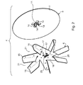
- Fig. 2 shows the fan 4 in an exploded view.
- Fig. 3 shows the fan 4 off Fig. 2 in the assembled state.
- the fan 4 is composed of a base plate 5 and a wing assembly 6 together.
- the base plate 5 has a circular disk element 7.
- the disk element 7 has a D-hole 11, as in FIG Figures 2 and 3 to recognize.
- the D-hole 11 is connected to a corresponding contour 12 of a rotational axis 3 defining the drive shaft 13 of the fan device 2 positively in the direction of rotation 18 about the rotation axis 3 in engagement, see Fig. 1 ,
- axial projections 14 for example, four axial projections 14, are formed on the disc member 7 .
- "Axial”, “radially” and “in the circumferential direction” refers in the present case to the axis of rotation 3, unless stated otherwise.
- the projections 14 are about the rotation axis 3, see Fig. 1 arranged uniformly distributed in the circumferential direction.
- the projections 14 are in the form of Formed hooks which are bent out of the main plane of extension of the disc member 7 so that they extend axially.
- the base plate 5 can be well made of sheet metal. This can be done by punching and bending a corresponding blank sheet metal.
- the wing assembly 6 comprises a plurality of wings 15, for example seven such wings 15.
- the wings 15 extend radially with respect to the axis of rotation 3.
- the wings 15 are held on a hub 16.
- the hub 16 has openings 14 corresponding to the projections 14.
- the projections 14 In the assembled state of the fan 4, the projections 14 each extend through an opening 17, see FIGS. 1 and 3 , This results in a positive connection in the direction of rotation 18 between the base plate 5 and the wing assembly. 6
- the wings 15 are arranged spaced apart in the circumferential direction, so that arise between these spaces 21.
- the disc member 7 has the same diameter as the wing assembly 6, as in FIG Fig. 3 to recognize. Thus, the gaps 21 are closed in the axial direction of the disk element 7.
- the wing assembly 6 is preferably also made of sheet metal, in particular by bending and punching.
- the base plate 5 and the wing assembly 6 are used in the operation of the fan device 2 together the vent guide.
- the drive shaft 13 has an axial stop 22.
- the fan device 2 comprises a nut 23.
- the nut 23 is screwed onto the free end 24 of the drive shaft 13 and presses the composite fan 4 against the stop 22. This prevents the arranged on the base plate 5 wing assembly 6 of the base plate 5 solves and in extreme cases even out of engagement with the projections 14 device.
- the free end 24 of the drive shaft 13 is through a central opening 25 (see Fig. 2 ) of the wing assembly 6 out.
- the opening 25 becomes, as in Fig. 1 to be seen, bounded by an edge region 26.
- the edge region 26 comprises a section 27 and a section 28, which adjoins the section 27.
- the shape of section 27 corresponds the envelope of a truncated cone on its circumference.
- the shape of the portion 28 corresponds to the envelope of a circular cylinder at its periphery.
- the nut 23 has a contour 27 corresponding to the section 27, with which it presses radially inwardly and at the same time axially on the section 27. For tightening the nut 23, a tool is used, which is supported on the then acting as a counter-projections 14.
- the drive shaft 13 is guided through a schematically illustrated opening 32 in a non-illustrated muffle back of the cooking device 1.
- the diameter of the opening 32 need only be slightly larger than that of the stopper 22, so that the drive shaft 13 during assembly of the fan device 2 in the cooking device 1 can be passed therethrough.
- a large opening, as required in the introductory known from the prior art solution due to the designed as a separate part driver can be avoided in the present case.
- a temperature loss and Wrasenaustrag is minimized through the opening 32.
- an electric motor, not shown, of the cooking appliance 1 can be arranged, which drives the fan device 2 for rotation about the rotation axis 3.
Landscapes
- Engineering & Computer Science (AREA)
- Mechanical Engineering (AREA)
- General Engineering & Computer Science (AREA)
- Structures Of Non-Positive Displacement Pumps (AREA)
Abstract
Description
- Die vorliegende Erfindung betrifft eine Lüftervorrichtung.
- Lüftervorrichtungen dienen zur gleichmäßigen Wärmeverteilung in einem Garraum eines Gargeräts. Beispielsweise beschreibt die
DE 10 2005 035 462 A1 eine solche Lüftervorrichtung. Die bekannte Lüftervorrichtung umfasst ein Lüfterrad und eine Antriebswelle. Auf der Antriebswelle ist ein Mitnehmer drehfest angeordnet. Der Mitnehmer umfasst Vorsprünge, welche in entsprechende Ausnehmungen in dem Lüfterrad greifen, wodurch die Antriebswelle mit dem Lüfterrad drehfest verbunden wird. Eine Mutter presst das Lüfterrad samt dem Mitnehmer axial gegen einen auf der Welle ausgebildeten Anschlag. Bei der bekannten Lösung ist der Mitnehmer als Separatteil ausgeführt, welches auf die Antriebswelle aufgepresst ist. - Aufgabe der vorliegenden Erfindung ist es, eine verbesserte Lüftervorrichtung bereitzustellen, welche sich bevorzugt einfach in ein Gargerät einbauen lässt.
- Daher wird eine Lüftervorrichtung für ein Gargerät, insbesondere für einen Backofen, vorgeschlagen, welche ein Lüfterrad aufweist. Das Lüfterrad umfasst eine Basisplatte und eine Flügelanordnung. Die Flügelanordnung ist auf der Basisplatte angeordnet und mit dieser in Drehrichtung formschlüssig verbunden.
- Aufgrund der formschlüssigen Verbindung zwischen der Basisplatte und der Flügelanordnung in Drehrichtung wird kein zusätzlicher Mitnehmer benötigt. Dies hat den Vorteil, dass sich die Antriebswelle bei der erfindungsgemäßen Lösung (ohne Mitnehmer) durch eine kleinere Öffnung in einer Muffelrückwand des Gargeräts zum Montieren der Lüftervorrichtung in dem Gargerät führen lässt. Die kleinere Öffnung ist mit einem geringen Temperaturverlust und Wrasenaustrag durch diese verbunden.
- Die Basisplatte und die Flügelanordnung können zusätzlich zu dem Formschluss in Drehrichtung noch anderweitig miteinander verbunden, beispielsweise vernietet, sein. Die Basisplatte und/oder die Flügelanordnungen können jeweils aus Blech und insbesondere durch Stanzen und/oder Biegen hergestellt sein.
- Das Gargerät ist vorliegend als Haushaltsgargerät ausgeführt.
- Gemäß einer Ausführungsform weist die Basisplatte zur formschlüssigen Verbindung mit der Flügelanordnung zumindest einen axialen Vorsprung auf, welcher in eine Öffnung in der Flügelanordnung greift.
- Bevorzugt sind mehrere axiale Vorsprünge, beispielsweise vier solcher Vorsprünge, vorgesehen, welche jeweils in eine entsprechende Öffnung in der Flügelanordnung greifen. Der eine oder die mehreren Vorsprünge fungieren als Mitnehmer, das heißt, sie nehmen die Flügelanordnung in der Drehrichtung mit. "Axial", "radial" und "in Umfangsrichtung" bezieht sich vorliegend auf eine Drehachse des Lüfterrads, soweit nichts anderes angegeben ist.
- Gemäß einer weiteren Ausführungsform ist der Vorsprung in Form eines Hakens ausgebildet, welcher aus der Haupterstreckungsebene der Basisplatte herausgebogen ist.
- Dadurch lässt sich der axiale Vorsprung einfach herstellen.
- Gemäß einer weiteren Ausführungsform umfasst die Flügelanordnung mehrere Flügel, welche in Umfangsrichtung Zwischenräume zwischen sich ausbilden.
- Eine solche Flügelanordnung lässt sich einfach herstellen.
- Gemäß einer weiteren Ausführungsform ist die Basisplatte derart ausgebildet, dass sie die Zwischenräume in axialer Richtung teilweise oder vollständig verschließt.
- Dazu kann die Basisplatte einen Durchmesser aufweisen, welcher zumindest so groß ist wie der Durchmesser der Flügelanordnung. Ein solches zweiteiliges Lüfterrad lässt sich einfach herstellen.
- Gemäß einer weiteren Ausführungsform ist eine Antriebswelle vorgesehen, welche mit der Basisplatte drehfest verbunden ist.
- Die Basisplatte überträgt dann die Drehbewegung mittels des Formschlusses auf die Flügelanordnung.
- Gemäß einer weiteren Ausführungsform ist die Antriebswelle zur drehfesten Verbindung mit der Basisplatte formschlüssig verbunden.
- Eine solche formschlüssige Verbindung lässt sich beispielsweise im Gegensatz zu der einleitend beschriebenen, kraftschlüssigen Presspassung einfach bei der Montage der Lüftervorrichtung in dem Gargerät, also beispielsweise nach Durchschieben der Antriebswelle durch die Öffnung in der Muffelrückwand, herstellen.
- Gemäß einer weiteren Ausführungsform weist die Basisplatte ein D-Loch auf, in welches die Antriebswelle mit einer entsprechenden Kontur derselben formschlüssig eingreift.
- Ein solches D-Loch lässt sich einfach herstellen, beispielsweise durch Ausstanzen.
- Gemäß einer weiteren Ausführungsform ist eine einen axialen Anschlag aufweisende Antriebswelle und eine Mutter vorgesehen, welche das Lüfterrad gegen den Anschlag presst.
- Dadurch ist sichergestellt, dass die Flügelanordnung sich nicht in axialer Richtung bewegt und dadurch außer Eingriff mit den Vorsprüngen der Basisplatte gerät, wodurch die formschlüssige Verbindung aufgehoben werden würde.
- Gemäß einer weiteren Ausführungsform presst die Mutter radial gegen die Flügelradanordnung.
- Dadurch wird erzielt, dass sich die Mutter auch unter den hohen im Betrieb der Lüftervorrichtung anzutreffenden Temperaturen im Gargerät nicht löst, ohne dass zusätzliche Sicherungselemente vorgesehen werden müssen.
- Gemäß einer weiteren Ausführungsform ist die Antriebswelle durch eine Öffnung in der Flügelradanordnung geführt.
- Die Öffnung ist beispielsweise als kreisrundes Loch ausgebildet.
- Gemäß einer weiteren Ausführungsform presst die Mutter radial gegen einen Randbereich der Öffnung.
- Dadurch lässt sich die gewünschte Presspassung einfach konstruktionstechnisch erzielen.
- Gemäß einer weiteren Ausführungsform weist der Randbereich einen Abschnitt in der Gestalt einer einen Kegelstumpf an dessen Umfang Umhüllenden auf, gegen welchen die Mutter presst.
- Eine Außenfläche des Abschnitts kann mit der Drehachse des Lüfterrads beispielsweise einen Winkel zwischen 5 und 10° einschließen.
- Gemäß einer weiteren Ausführungsform weist der Randbereich einen weiteren Abschnitt auf, welcher sich an den Abschnitt anschließt und die Antriebswelle führt. Der weitere Abschnitt kann die Gestalt einer einen Kreiszylinder an dessen Umfang Umhüllenden aufweisen.
- Dadurch wird ein Verkanten der Flügelanordnung gegenüber der Antriebswelle beim Aufschieben der Flügelanordnung auf die Antriebswelle vermieden.
- Gemäß einer weiteren Ausführungsform ist der Vorsprung als Gegenhalter für ein Werkzeug zum Aufschrauben der Mutter ausgebildet.
- Dadurch wird ein Gegenhalten beispielsweise an der Flügelradanordnung und damit ein etwaiges Verbiegen derselben vermieden.
- Weitere vorteilhafte Ausgestaltungen und Aspekte der Erfindung sind Gegenstand der Unteransprüche sowie der im Folgenden beschriebenen Ausführungsbeispiele der Erfindung. Im Weiteren wird die Erfindung anhand von bevorzugten Ausführungsformen unter Bezugnahme auf die beiliegenden Figuren näher erläutert.
- Es zeigt dabei:
-
Fig. 1 : ein schematisch angedeutetes Gargerät mit einer Lüftervorrichtung, welche im Schnitt dargestellt ist, gemäß einer Ausführungsform; -
Fig. 2 : in einer Explosionsansicht ein Lüfterrad der Lüftervorrichtung ausFig. 1 ; und -
Fig. 3 : das Lüfterrad ausFig. 2 im zusammengesetzten Zustand. - In den Figuren sind gleiche oder funktionsgleiche Elemente mit denselben Bezugszeichen versehen worden, soweit nichts anderes angegeben ist.
-
Fig. 1 zeigt schematisch ein Gargerät 1. - Das Gargerät 1 ist in Form eines Haushaltsgargeräts, insbesondere in Form eines Backofens, ausgebildet. In dem Gargerät 1 ist eine Lüftervorrichtung 2 angeordnet. Die Lüftervorrichtung 2 ist im Schnitt durch eine Drehachse 3 derselben dargestellt. Die Lüftervorrichtung 2 umfasst ein Lüfterrad 4.
-
Fig. 2 zeigt das Lüfterrad 4 in einer Explosionsansicht.Fig. 3 zeigt das Lüfterrad 4 ausFig. 2 im zusammengesetzten Zustand. - Wie in
Fig. 2 gezeigt, setzt sich das Lüfterrad 4 aus einer Basisplatte 5 und einer Flügelanordnung 6 zusammen. Die Basisplatte 5 weist ein kreisrundes Scheibenelement 7 auf. Mittig weist das Scheibenelement 7 ein D-Loch 11 auf, wie inFiguren 2 und3 zu erkennen. Das D-Loch 11 steht mit einer entsprechenden Kontur 12 einer die Drehachse 3 definierenden Antriebswelle 13 der Lüftervorrichtung 2 formschlüssig in Drehrichtung 18 um die Drehachse 3 in Eingriff, sieheFig. 1 . - Nun zurückkehrend zu
Fig. 2 ist dort weiter gezeigt, dass an dem Scheibenelement 7 axiale Vorsprünge 14, beispielsweise vier axiale Vorsprünge 14, ausgebildet sind. "Axial", "radial" und "in Umfangsrichtung" bezieht sich vorliegend auf die Drehachse 3, soweit nichts anderes angegeben ist. Die Vorsprünge 14 sind um die Drehachse 3, sieheFig. 1 , gleichmäßig in Umfangsrichtung verteilt angeordnet. Die Vorsprünge 14 sind in Form von Haken ausgebildet, welche aus der Haupterstreckungsebene des Scheibenelements 7 herausgebogen sind, so dass sie sich axial erstrecken. Die Basisplatte 5 lässt sich gut aus Blech herstellen. Dies kann durch Stanzen und Biegen eines entsprechenden Blechrohlings geschehen. - Die Flügelanordnung 6 umfasst mehrere Flügel 15, beispielsweise sieben solcher Flügel 15. Die Flügel 15 erstrecken sich radial bezogen auf die Drehachse 3. Die Flügel 15 sind an einer Nabe 16 gehalten. Die Nabe 16 weist zu den Vorsprüngen 14 korrespondierende Öffnungen 17 auf. Im zusammengesetzten Zustand des Lüfterrads 4 erstrecken sich die Vorsprünge 14 jeweils durch eine Öffnung 17, siehe
Figuren 1 und3 . Dadurch ergibt sich ein Formschluss in Drehrichtung 18 zwischen der Basisplatte 5 und der Flügelanordnung 6. - Die Flügel 15 sind in Umfangsrichtung voneinander beabstandet angeordnet, so dass sich zwischen diesen Zwischenräume 21 ergeben. Das Scheibenelement 7 weist denselben Durchmesser auf wie die Flügelanordnung 6, wie in
Fig. 3 zu erkennen. Somit werden die Zwischenräume 21 in axialer Richtung von dem Scheibenelement 7 verschlossen. Die Flügelanordnung 6 ist bevorzugt ebenfalls aus Blech, insbesondere durch Biegen und Stanzen hergestellt. - Die Basisplatte 5 und die Flügelanordnung 6 dienen im Betrieb der Lüftervorrichtung 2 gemeinsam der Lüftführung.
- Zurückkehrend zu
Fig. 1 ist dort gezeigt, dass die Antriebswelle 13 einen axialen Anschlag 22 aufweist. Außerdem umfasst die Lüftervorrichtung 2 eine Mutter 23. Die Mutter 23 ist auf das freie Ende 24 der Antriebswelle 13 aufgeschraubt und presst das zusammengesetzte Lüfterrad 4 gegen den Anschlag 22. Dadurch wird verhindert, dass sich die auf der Basisplatte 5 angeordnete Flügelanordnung 6 von der Basisplatte 5 löst und im Extremfall sogar außer Eingriff mit den Vorsprüngen 14 gerät. - Das freie Ende 24 der Antriebswelle 13 ist durch eine mittige Öffnung 25 (siehe
Fig. 2 ) der Flügelanordnung 6 geführt. Die Öffnung 25 wird, wie inFig. 1 zu sehen, von einem Randbereich 26 begrenzt. Der Randbereich 26 umfasst einen Abschnitt 27 und einen Abschnitt 28, welcher sich an den Abschnitt 27 anschließt. Die Gestalt des Abschnitts 27 entspricht der Umhüllenden eines Kegelstumpfes an dessen Umfang. Die Gestalt des Abschnitts 28 entspricht der Umhüllenden eines Kreiszylinders an dessen Umfang. Die Mutter 23 weist eine dem Abschnitt 27 entsprechende Kontur 31 auf, mit welcher sie radial nach innen und gleichzeitig axial auf den Abschnitt 27 presst. Zum Festziehen der Mutter 23 wird ein Werkzeug verwendet, welches sich an den dann als Gegenhalter fungierenden Vorsprüngen 14 abstützt. - Die Antriebswelle 13 ist durch eine schematisch dargestellte Öffnung 32 in einer nicht näher dargestellten Muffelrückwand des Gargeräts 1 geführt. Der Durchmesser der Öffnung 32 muss lediglich geringfügig größer sein als der des Anschlags 22, damit die Antriebswelle 13 bei der Montage der Lüftervorrichtung 2 in dem Gargerät 1 durch diese hindurchgeführt werden kann. Eine große Öffnung, wie sie bei der einleitend, aus dem Stand der Technik bekannten Lösung aufgrund des als Separatteil ausgeführten Mitnehmers erforderlich ist, kann vorliegend vermieden werden. Dadurch wird ein Temperaturverlust und Wrasenaustrag durch die Öffnung 32 minimiert. Hinter der Öffnung 32 kann ein nicht gezeigter Elektromotor des Gargeräts 1 angeordnet sein, welcher die Lüftervorrichtung 2 zum Drehen um die Drehachse 3 antreibt.
- Obwohl die vorliegende Erfindung anhand von Ausführungsbeispielen beschrieben wurde, ist sie vielfältig modifizierbar.
-
- 1
- Gargerät
- 2
- Lüftervorrichtung
- 3
- Drehachse
- 4
- Lüfterrad
- 5
- Basisplatte
- 6
- Flügelanordnung
- 7
- Scheibenelement
- 11
- D-Loch
- 12
- Kontur
- 13
- Antriebswelle
- 14
- Vorsprung
- 15
- Flügel
- 16
- Nabe
- 17
- Öffnung
- 18
- Drehrichtung
- 21
- Zwischenraum
- 22
- Anschlag
- 23
- Mutter
- 24
- Ende
- 25
- Öffnung
- 26
- Randbereich
- 27
- Abschnitt
- 28
- Abschnitt
- 31
- Kontaktfläche
- 32
- Öffnung
Claims (15)
- Lüftervorrichtung (2) für ein Gargerät (1), insbesondere für einen Backofen, mit einem Lüfterrad (4), welches eine Basisplatte (5) und eine Flügelanordnung (6) umfasst, die auf der Basisplatte (5) angeordnet und mit dieser in Drehrichtung (18) formschlüssig verbunden ist.
- Lüftervorrichtung nach Anspruch 1, dadurch gekennzeichnet, dass die Basisplatte (5) zur formschlüssigen Verbindung mit der Flügelanordnung (6) zumindest einen axialen Vorsprung (14) aufweist, welcher in eine Öffnung (17) in der Flügelanordnung (6) greift.
- Lüfteranordnung nach Anspruch 2, dadurch gekennzeichnet, dass der Vorsprung (14) in Form eines Hakens ausgebildet, welcher aus der Haupterstreckungsebene der Basisplatte (5) herausgebogen ist.
- Lüftervorrichtung nach einem der Ansprüche 1 - 3, dadurch gekennzeichnet, dass die Flügelanordnung (6) mehrere Flügel (15) umfasst, welche in Umfangsrichtung Zwischenräume (21) zwischen sich ausbilden.
- Lüftervorrichtung nach Anspruch 4, dadurch gekennzeichnet, dass die Basisplatte (5) derart ausgebildet ist, dass sie die Zwischenräume (21) in axialer Richtung teilweise oder vollständig verschließt.
- Lüftervorrichtung nach einem der Ansprüche 1 - 5, dadurch gekennzeichnet, dass eine Antriebswelle (13) vorgesehen ist, welche mit der Basisplatte (5) drehfest verbunden ist.
- Lüftervorrichtung nach Anspruch 6, dadurch gekennzeichnet, dass die Antriebswelle (13) zur drehfesten Verbindung mit der Basisplatte (5) formschlüssig verbunden ist.
- Lüftervorrichtung nach Anspruch 7, dadurch gekennzeichnet, dass die Basisplatte (5) ein D-Loch (11) aufweist, in welches die Antriebswelle (13) mit einer entsprechenden Kontur (12) derselben formschlüssig eingreift.
- Lüftervorrichtung nach einem der Ansprüche 1 - 8, dadurch gekennzeichnet, dass eine einen axialen Anschlag (22) aufweisende Antriebswelle (13) und eine Mutter (23) vorgesehen sind, wobei die Mutter (23) das Lüfterrad (4) gegen den Anschlag (22) presst.
- Lüftervorrichtung nach Anspruch 9, dadurch gekennzeichnet, dass die Mutter (23) radial gegen die Flügelanordnung (6) presst.
- Lüftervorrichtung nach Anspruch 9 oder 10, dadurch gekennzeichnet, dass die Antriebswelle (13) durch eine Öffnung (25) in der Flügelanordnung (6) geführt ist.
- Lüftervorrichtung nach Anspruch 11, dadurch gekennzeichnet, dass die Mutter (23) radial gegen einen Randbereich (26) der Öffnung (25) presst.
- Lüftervorrichtung nach Anspruch 12, dadurch gekennzeichnet, dass der Randbereich (26) einen Abschnitt (27) in der Gestalt einer einen Kegelstumpf an dessen Umfang Umhüllenden aufweist, gegen welchen die Mutter (23) presst.
- Lüftervorrichtung nach einem der Ansprüche 9 - 13, dadurch gekennzeichnet, dass der Vorsprung (14) als Gegenhalter für ein Werkzeug zum Aufschrauben der Mutter (23) ausgebildet ist.
- Gargerät (1) mit einer Lüftervorrichtung (2) nach einem der Ansprüche 1 - 14.
Applications Claiming Priority (1)
| Application Number | Priority Date | Filing Date | Title |
|---|---|---|---|
| DE102012217349.8A DE102012217349A1 (de) | 2012-09-26 | 2012-09-26 | Lüftervorrichtung |
Publications (3)
| Publication Number | Publication Date |
|---|---|
| EP2713059A2 true EP2713059A2 (de) | 2014-04-02 |
| EP2713059A3 EP2713059A3 (de) | 2017-08-02 |
| EP2713059B1 EP2713059B1 (de) | 2020-04-22 |
Family
ID=49182083
Family Applications (1)
| Application Number | Title | Priority Date | Filing Date |
|---|---|---|---|
| EP13183834.4A Active EP2713059B1 (de) | 2012-09-26 | 2013-09-11 | Lüftervorrichtung |
Country Status (2)
| Country | Link |
|---|---|
| EP (1) | EP2713059B1 (de) |
| DE (1) | DE102012217349A1 (de) |
Cited By (2)
| Publication number | Priority date | Publication date | Assignee | Title |
|---|---|---|---|---|
| CN112283152A (zh) * | 2020-10-15 | 2021-01-29 | 青岛海尔智慧厨房电器有限公司 | 一种双向扇叶及厨房电器 |
| CN117167322A (zh) * | 2021-09-24 | 2023-12-05 | 上海必修福企业管理有限公司 | 静音风扇叶、风扇及制作方法 |
Citations (1)
| Publication number | Priority date | Publication date | Assignee | Title |
|---|---|---|---|---|
| DE102005035462A1 (de) | 2005-07-28 | 2007-02-01 | BSH Bosch und Siemens Hausgeräte GmbH | Gebläsevorrichtung für ein Gargerät |
Family Cites Families (5)
| Publication number | Priority date | Publication date | Assignee | Title |
|---|---|---|---|---|
| DE1957988C3 (de) * | 1969-11-18 | 1974-05-02 | Wilhelm 8090 Wasserburg Gronbach | Radial-Lüfterrad für Gebläse |
| US4174559A (en) * | 1978-02-09 | 1979-11-20 | J.J. & M. | Fastening method |
| DE3039035A1 (de) * | 1980-10-16 | 1982-04-29 | Ebm Elektrobau Mulfingen Gmbh & Co, 7119 Mulfingen | Luefter |
| US7484934B2 (en) * | 2006-04-26 | 2009-02-03 | Field Controls, Llc | Method and apparatus for propelling an intercepted fluid |
| FR2908941B1 (fr) * | 2006-11-22 | 2014-03-14 | Valeo Equip Electr Moteur | Procede de realisation d'un dispositif ventilateur pour machine electrique tournante et dispositif ventilateur pour la mise en oeuvre de ce procede |
-
2012
- 2012-09-26 DE DE102012217349.8A patent/DE102012217349A1/de not_active Withdrawn
-
2013
- 2013-09-11 EP EP13183834.4A patent/EP2713059B1/de active Active
Patent Citations (1)
| Publication number | Priority date | Publication date | Assignee | Title |
|---|---|---|---|---|
| DE102005035462A1 (de) | 2005-07-28 | 2007-02-01 | BSH Bosch und Siemens Hausgeräte GmbH | Gebläsevorrichtung für ein Gargerät |
Cited By (2)
| Publication number | Priority date | Publication date | Assignee | Title |
|---|---|---|---|---|
| CN112283152A (zh) * | 2020-10-15 | 2021-01-29 | 青岛海尔智慧厨房电器有限公司 | 一种双向扇叶及厨房电器 |
| CN117167322A (zh) * | 2021-09-24 | 2023-12-05 | 上海必修福企业管理有限公司 | 静音风扇叶、风扇及制作方法 |
Also Published As
| Publication number | Publication date |
|---|---|
| EP2713059A3 (de) | 2017-08-02 |
| EP2713059B1 (de) | 2020-04-22 |
| DE102012217349A1 (de) | 2014-03-27 |
Similar Documents
| Publication | Publication Date | Title |
|---|---|---|
| EP1934483B1 (de) | Ventilatorrad | |
| EP2904270B1 (de) | Gehäuse für einen axialventilator | |
| DE2121919C3 (de) | Reibungskupplung | |
| DE102010046017A1 (de) | Aufwärmwerkzeug für Lagerringe | |
| EP2713059B1 (de) | Lüftervorrichtung | |
| EP2531702A2 (de) | Vorrichtung zum verändern der steuerzeiten von gaswechselventilen einer brennkraftmaschine | |
| DE102014203416A1 (de) | Reibungskupplung | |
| DE102012004459B4 (de) | Antrieb mit Drehmomentstütze zur axial und radial weniger als in Umfangsrichtung steifen Befestigung des Gehäuses eines Winkelsensors an einem Lüfterhaubengitter eines Elektromotors | |
| WO2015048955A2 (de) | Rotorpressverband mit verbindungsvorsprüngen und / oder deformationsausnehmungen im rotorpaket | |
| EP1913263B1 (de) | Gebläsevorrichtung für ein gargerät | |
| DE202013100139U1 (de) | Verbund aus einem Schutzgitter und einem Wandring sowie Lüfter mit einem derartigen Verbund | |
| EP2619885B1 (de) | Verfahren zum herstellen einer gehäuseanordnung, gehäuseanordnung sowie stempelvorrichtung | |
| DE102015211477A1 (de) | Hydrostatischer Kupplungsaktor | |
| DE102007042810A1 (de) | Anordnung zur axialen Abstützung einer Endlamelle eines Lamellenpaketes mittels eines Sprengringes | |
| EP3415782A1 (de) | Bremsscheibe und scheibenbremse | |
| EP1754906B1 (de) | Anbindung eines Zentralausrückers an eine Kupplung | |
| DE102004031159B4 (de) | Gebläsevorrichtung | |
| EP3428540B1 (de) | Kochplattenvorrichtung mit einer kochplatte und kochfeld | |
| DE102007056748A1 (de) | Bremsscheiben/Nabenverbindung | |
| DE102013114112A1 (de) | Außenläufermotor, Lüftervorrichtung sowie Montage- und Demontageverfahren | |
| EP3155277A1 (de) | Kupplungsvorrichtung | |
| EP3157772B1 (de) | Befestigungsanordnung | |
| EP2740871B1 (de) | Vorrichtung für ein Haushaltsgerät mit einem Scharnier und einer Koppeleinrichtung sowie Haushaltsgerät mit einer derartigen Vorrichtung | |
| DE102016215146B4 (de) | Anordnung eines Torsionsschwingungsdämpfers an einem Lamellenträger | |
| DE102011120430A1 (de) | Lüftervorrichtung eines Kraftfahrzeugs |
Legal Events
| Date | Code | Title | Description |
|---|---|---|---|
| PUAI | Public reference made under article 153(3) epc to a published international application that has entered the european phase |
Free format text: ORIGINAL CODE: 0009012 |
|
| AK | Designated contracting states |
Kind code of ref document: A2 Designated state(s): AL AT BE BG CH CY CZ DE DK EE ES FI FR GB GR HR HU IE IS IT LI LT LU LV MC MK MT NL NO PL PT RO RS SE SI SK SM TR |
|
| AX | Request for extension of the european patent |
Extension state: BA ME |
|
| RAP1 | Party data changed (applicant data changed or rights of an application transferred) |
Owner name: BSH HAUSGERAETE GMBH |
|
| PUAL | Search report despatched |
Free format text: ORIGINAL CODE: 0009013 |
|
| AK | Designated contracting states |
Kind code of ref document: A3 Designated state(s): AL AT BE BG CH CY CZ DE DK EE ES FI FR GB GR HR HU IE IS IT LI LT LU LV MC MK MT NL NO PL PT RO RS SE SI SK SM TR |
|
| AX | Request for extension of the european patent |
Extension state: BA ME |
|
| RIC1 | Information provided on ipc code assigned before grant |
Ipc: F04D 29/02 20060101AFI20170626BHEP Ipc: F04D 29/28 20060101ALI20170626BHEP Ipc: F04D 29/62 20060101ALI20170626BHEP |
|
| STAA | Information on the status of an ep patent application or granted ep patent |
Free format text: STATUS: REQUEST FOR EXAMINATION WAS MADE |
|
| 17P | Request for examination filed |
Effective date: 20180202 |
|
| RBV | Designated contracting states (corrected) |
Designated state(s): AL AT BE BG CH CY CZ DE DK EE ES FI FR GB GR HR HU IE IS IT LI LT LU LV MC MK MT NL NO PL PT RO RS SE SI SK SM TR |
|
| GRAP | Despatch of communication of intention to grant a patent |
Free format text: ORIGINAL CODE: EPIDOSNIGR1 |
|
| STAA | Information on the status of an ep patent application or granted ep patent |
Free format text: STATUS: GRANT OF PATENT IS INTENDED |
|
| INTG | Intention to grant announced |
Effective date: 20191129 |
|
| GRAS | Grant fee paid |
Free format text: ORIGINAL CODE: EPIDOSNIGR3 |
|
| GRAA | (expected) grant |
Free format text: ORIGINAL CODE: 0009210 |
|
| STAA | Information on the status of an ep patent application or granted ep patent |
Free format text: STATUS: THE PATENT HAS BEEN GRANTED |
|
| AK | Designated contracting states |
Kind code of ref document: B1 Designated state(s): AL AT BE BG CH CY CZ DE DK EE ES FI FR GB GR HR HU IE IS IT LI LT LU LV MC MK MT NL NO PL PT RO RS SE SI SK SM TR |
|
| REG | Reference to a national code |
Ref country code: GB Ref legal event code: FG4D Free format text: NOT ENGLISH |
|
| REG | Reference to a national code |
Ref country code: CH Ref legal event code: EP |
|
| REG | Reference to a national code |
Ref country code: IE Ref legal event code: FG4D Free format text: LANGUAGE OF EP DOCUMENT: GERMAN |
|
| REG | Reference to a national code |
Ref country code: DE Ref legal event code: R096 Ref document number: 502013014610 Country of ref document: DE |
|
| REG | Reference to a national code |
Ref country code: AT Ref legal event code: REF Ref document number: 1260476 Country of ref document: AT Kind code of ref document: T Effective date: 20200515 |
|
| REG | Reference to a national code |
Ref country code: LT Ref legal event code: MG4D |
|
| REG | Reference to a national code |
Ref country code: NL Ref legal event code: MP Effective date: 20200422 |
|
| PG25 | Lapsed in a contracting state [announced via postgrant information from national office to epo] |
Ref country code: IS Free format text: LAPSE BECAUSE OF FAILURE TO SUBMIT A TRANSLATION OF THE DESCRIPTION OR TO PAY THE FEE WITHIN THE PRESCRIBED TIME-LIMIT Effective date: 20200822 Ref country code: GR Free format text: LAPSE BECAUSE OF FAILURE TO SUBMIT A TRANSLATION OF THE DESCRIPTION OR TO PAY THE FEE WITHIN THE PRESCRIBED TIME-LIMIT Effective date: 20200723 Ref country code: NO Free format text: LAPSE BECAUSE OF FAILURE TO SUBMIT A TRANSLATION OF THE DESCRIPTION OR TO PAY THE FEE WITHIN THE PRESCRIBED TIME-LIMIT Effective date: 20200722 Ref country code: FI Free format text: LAPSE BECAUSE OF FAILURE TO SUBMIT A TRANSLATION OF THE DESCRIPTION OR TO PAY THE FEE WITHIN THE PRESCRIBED TIME-LIMIT Effective date: 20200422 Ref country code: SE Free format text: LAPSE BECAUSE OF FAILURE TO SUBMIT A TRANSLATION OF THE DESCRIPTION OR TO PAY THE FEE WITHIN THE PRESCRIBED TIME-LIMIT Effective date: 20200422 Ref country code: PT Free format text: LAPSE BECAUSE OF FAILURE TO SUBMIT A TRANSLATION OF THE DESCRIPTION OR TO PAY THE FEE WITHIN THE PRESCRIBED TIME-LIMIT Effective date: 20200824 Ref country code: LT Free format text: LAPSE BECAUSE OF FAILURE TO SUBMIT A TRANSLATION OF THE DESCRIPTION OR TO PAY THE FEE WITHIN THE PRESCRIBED TIME-LIMIT Effective date: 20200422 Ref country code: NL Free format text: LAPSE BECAUSE OF FAILURE TO SUBMIT A TRANSLATION OF THE DESCRIPTION OR TO PAY THE FEE WITHIN THE PRESCRIBED TIME-LIMIT Effective date: 20200422 |
|
| PG25 | Lapsed in a contracting state [announced via postgrant information from national office to epo] |
Ref country code: BG Free format text: LAPSE BECAUSE OF FAILURE TO SUBMIT A TRANSLATION OF THE DESCRIPTION OR TO PAY THE FEE WITHIN THE PRESCRIBED TIME-LIMIT Effective date: 20200722 Ref country code: RS Free format text: LAPSE BECAUSE OF FAILURE TO SUBMIT A TRANSLATION OF THE DESCRIPTION OR TO PAY THE FEE WITHIN THE PRESCRIBED TIME-LIMIT Effective date: 20200422 Ref country code: LV Free format text: LAPSE BECAUSE OF FAILURE TO SUBMIT A TRANSLATION OF THE DESCRIPTION OR TO PAY THE FEE WITHIN THE PRESCRIBED TIME-LIMIT Effective date: 20200422 Ref country code: HR Free format text: LAPSE BECAUSE OF FAILURE TO SUBMIT A TRANSLATION OF THE DESCRIPTION OR TO PAY THE FEE WITHIN THE PRESCRIBED TIME-LIMIT Effective date: 20200422 |
|
| PG25 | Lapsed in a contracting state [announced via postgrant information from national office to epo] |
Ref country code: AL Free format text: LAPSE BECAUSE OF FAILURE TO SUBMIT A TRANSLATION OF THE DESCRIPTION OR TO PAY THE FEE WITHIN THE PRESCRIBED TIME-LIMIT Effective date: 20200422 |
|
| REG | Reference to a national code |
Ref country code: DE Ref legal event code: R097 Ref document number: 502013014610 Country of ref document: DE |
|
| PG25 | Lapsed in a contracting state [announced via postgrant information from national office to epo] |
Ref country code: DK Free format text: LAPSE BECAUSE OF FAILURE TO SUBMIT A TRANSLATION OF THE DESCRIPTION OR TO PAY THE FEE WITHIN THE PRESCRIBED TIME-LIMIT Effective date: 20200422 Ref country code: EE Free format text: LAPSE BECAUSE OF FAILURE TO SUBMIT A TRANSLATION OF THE DESCRIPTION OR TO PAY THE FEE WITHIN THE PRESCRIBED TIME-LIMIT Effective date: 20200422 Ref country code: SM Free format text: LAPSE BECAUSE OF FAILURE TO SUBMIT A TRANSLATION OF THE DESCRIPTION OR TO PAY THE FEE WITHIN THE PRESCRIBED TIME-LIMIT Effective date: 20200422 Ref country code: CZ Free format text: LAPSE BECAUSE OF FAILURE TO SUBMIT A TRANSLATION OF THE DESCRIPTION OR TO PAY THE FEE WITHIN THE PRESCRIBED TIME-LIMIT Effective date: 20200422 Ref country code: RO Free format text: LAPSE BECAUSE OF FAILURE TO SUBMIT A TRANSLATION OF THE DESCRIPTION OR TO PAY THE FEE WITHIN THE PRESCRIBED TIME-LIMIT Effective date: 20200422 Ref country code: IT Free format text: LAPSE BECAUSE OF FAILURE TO SUBMIT A TRANSLATION OF THE DESCRIPTION OR TO PAY THE FEE WITHIN THE PRESCRIBED TIME-LIMIT Effective date: 20200422 Ref country code: ES Free format text: LAPSE BECAUSE OF FAILURE TO SUBMIT A TRANSLATION OF THE DESCRIPTION OR TO PAY THE FEE WITHIN THE PRESCRIBED TIME-LIMIT Effective date: 20200422 |
|
| PG25 | Lapsed in a contracting state [announced via postgrant information from national office to epo] |
Ref country code: PL Free format text: LAPSE BECAUSE OF FAILURE TO SUBMIT A TRANSLATION OF THE DESCRIPTION OR TO PAY THE FEE WITHIN THE PRESCRIBED TIME-LIMIT Effective date: 20200422 Ref country code: SK Free format text: LAPSE BECAUSE OF FAILURE TO SUBMIT A TRANSLATION OF THE DESCRIPTION OR TO PAY THE FEE WITHIN THE PRESCRIBED TIME-LIMIT Effective date: 20200422 |
|
| PLBE | No opposition filed within time limit |
Free format text: ORIGINAL CODE: 0009261 |
|
| STAA | Information on the status of an ep patent application or granted ep patent |
Free format text: STATUS: NO OPPOSITION FILED WITHIN TIME LIMIT |
|
| 26N | No opposition filed |
Effective date: 20210125 |
|
| PG25 | Lapsed in a contracting state [announced via postgrant information from national office to epo] |
Ref country code: MC Free format text: LAPSE BECAUSE OF FAILURE TO SUBMIT A TRANSLATION OF THE DESCRIPTION OR TO PAY THE FEE WITHIN THE PRESCRIBED TIME-LIMIT Effective date: 20200422 |
|
| REG | Reference to a national code |
Ref country code: CH Ref legal event code: PL |
|
| PG25 | Lapsed in a contracting state [announced via postgrant information from national office to epo] |
Ref country code: SI Free format text: LAPSE BECAUSE OF FAILURE TO SUBMIT A TRANSLATION OF THE DESCRIPTION OR TO PAY THE FEE WITHIN THE PRESCRIBED TIME-LIMIT Effective date: 20200422 |
|
| REG | Reference to a national code |
Ref country code: BE Ref legal event code: MM Effective date: 20200930 |
|
| PG25 | Lapsed in a contracting state [announced via postgrant information from national office to epo] |
Ref country code: LU Free format text: LAPSE BECAUSE OF NON-PAYMENT OF DUE FEES Effective date: 20200911 |
|
| PG25 | Lapsed in a contracting state [announced via postgrant information from national office to epo] |
Ref country code: FR Free format text: LAPSE BECAUSE OF NON-PAYMENT OF DUE FEES Effective date: 20200930 |
|
| PG25 | Lapsed in a contracting state [announced via postgrant information from national office to epo] |
Ref country code: CH Free format text: LAPSE BECAUSE OF NON-PAYMENT OF DUE FEES Effective date: 20200930 Ref country code: BE Free format text: LAPSE BECAUSE OF NON-PAYMENT OF DUE FEES Effective date: 20200930 Ref country code: LI Free format text: LAPSE BECAUSE OF NON-PAYMENT OF DUE FEES Effective date: 20200930 Ref country code: IE Free format text: LAPSE BECAUSE OF NON-PAYMENT OF DUE FEES Effective date: 20200911 |
|
| REG | Reference to a national code |
Ref country code: AT Ref legal event code: MM01 Ref document number: 1260476 Country of ref document: AT Kind code of ref document: T Effective date: 20200911 |
|
| PG25 | Lapsed in a contracting state [announced via postgrant information from national office to epo] |
Ref country code: AT Free format text: LAPSE BECAUSE OF NON-PAYMENT OF DUE FEES Effective date: 20200911 |
|
| PG25 | Lapsed in a contracting state [announced via postgrant information from national office to epo] |
Ref country code: TR Free format text: LAPSE BECAUSE OF FAILURE TO SUBMIT A TRANSLATION OF THE DESCRIPTION OR TO PAY THE FEE WITHIN THE PRESCRIBED TIME-LIMIT Effective date: 20200422 Ref country code: MT Free format text: LAPSE BECAUSE OF FAILURE TO SUBMIT A TRANSLATION OF THE DESCRIPTION OR TO PAY THE FEE WITHIN THE PRESCRIBED TIME-LIMIT Effective date: 20200422 Ref country code: CY Free format text: LAPSE BECAUSE OF FAILURE TO SUBMIT A TRANSLATION OF THE DESCRIPTION OR TO PAY THE FEE WITHIN THE PRESCRIBED TIME-LIMIT Effective date: 20200422 |
|
| PG25 | Lapsed in a contracting state [announced via postgrant information from national office to epo] |
Ref country code: MK Free format text: LAPSE BECAUSE OF FAILURE TO SUBMIT A TRANSLATION OF THE DESCRIPTION OR TO PAY THE FEE WITHIN THE PRESCRIBED TIME-LIMIT Effective date: 20200422 |
|
| REG | Reference to a national code |
Ref country code: DE Ref legal event code: R084 Ref document number: 502013014610 Country of ref document: DE |
|
| PGFP | Annual fee paid to national office [announced via postgrant information from national office to epo] |
Ref country code: DE Payment date: 20250930 Year of fee payment: 13 |
|
| PGFP | Annual fee paid to national office [announced via postgrant information from national office to epo] |
Ref country code: GB Payment date: 20250923 Year of fee payment: 13 |