EP2713052B1 - Zahnradmaschine mit einer Nut zur Aufnahme eines Einlaufgrates - Google Patents
Zahnradmaschine mit einer Nut zur Aufnahme eines Einlaufgrates Download PDFInfo
- Publication number
- EP2713052B1 EP2713052B1 EP13181923.7A EP13181923A EP2713052B1 EP 2713052 B1 EP2713052 B1 EP 2713052B1 EP 13181923 A EP13181923 A EP 13181923A EP 2713052 B1 EP2713052 B1 EP 2713052B1
- Authority
- EP
- European Patent Office
- Prior art keywords
- groove
- peripheral surface
- inner peripheral
- assigned
- main body
- Prior art date
- Legal status (The legal status is an assumption and is not a legal conclusion. Google has not performed a legal analysis and makes no representation as to the accuracy of the status listed.)
- Not-in-force
Links
Images


Classifications
-
- F—MECHANICAL ENGINEERING; LIGHTING; HEATING; WEAPONS; BLASTING
- F04—POSITIVE - DISPLACEMENT MACHINES FOR LIQUIDS; PUMPS FOR LIQUIDS OR ELASTIC FLUIDS
- F04C—ROTARY-PISTON, OR OSCILLATING-PISTON, POSITIVE-DISPLACEMENT MACHINES FOR LIQUIDS; ROTARY-PISTON, OR OSCILLATING-PISTON, POSITIVE-DISPLACEMENT PUMPS
- F04C2/00—Rotary-piston machines or pumps
- F04C2/08—Rotary-piston machines or pumps of intermeshing-engagement type, i.e. with engagement of co-operating members similar to that of toothed gearing
- F04C2/082—Details specially related to intermeshing engagement type machines or pumps
- F04C2/086—Carter
-
- F—MECHANICAL ENGINEERING; LIGHTING; HEATING; WEAPONS; BLASTING
- F04—POSITIVE - DISPLACEMENT MACHINES FOR LIQUIDS; PUMPS FOR LIQUIDS OR ELASTIC FLUIDS
- F04C—ROTARY-PISTON, OR OSCILLATING-PISTON, POSITIVE-DISPLACEMENT MACHINES FOR LIQUIDS; ROTARY-PISTON, OR OSCILLATING-PISTON, POSITIVE-DISPLACEMENT PUMPS
- F04C2/00—Rotary-piston machines or pumps
- F04C2/08—Rotary-piston machines or pumps of intermeshing-engagement type, i.e. with engagement of co-operating members similar to that of toothed gearing
- F04C2/12—Rotary-piston machines or pumps of intermeshing-engagement type, i.e. with engagement of co-operating members similar to that of toothed gearing of other than internal-axis type
- F04C2/14—Rotary-piston machines or pumps of intermeshing-engagement type, i.e. with engagement of co-operating members similar to that of toothed gearing of other than internal-axis type with toothed rotary pistons
- F04C2/18—Rotary-piston machines or pumps of intermeshing-engagement type, i.e. with engagement of co-operating members similar to that of toothed gearing of other than internal-axis type with toothed rotary pistons with similar tooth forms
-
- F—MECHANICAL ENGINEERING; LIGHTING; HEATING; WEAPONS; BLASTING
- F04—POSITIVE - DISPLACEMENT MACHINES FOR LIQUIDS; PUMPS FOR LIQUIDS OR ELASTIC FLUIDS
- F04C—ROTARY-PISTON, OR OSCILLATING-PISTON, POSITIVE-DISPLACEMENT MACHINES FOR LIQUIDS; ROTARY-PISTON, OR OSCILLATING-PISTON, POSITIVE-DISPLACEMENT PUMPS
- F04C2230/00—Manufacture
- F04C2230/10—Manufacture by removing material
-
- F—MECHANICAL ENGINEERING; LIGHTING; HEATING; WEAPONS; BLASTING
- F04—POSITIVE - DISPLACEMENT MACHINES FOR LIQUIDS; PUMPS FOR LIQUIDS OR ELASTIC FLUIDS
- F04C—ROTARY-PISTON, OR OSCILLATING-PISTON, POSITIVE-DISPLACEMENT MACHINES FOR LIQUIDS; ROTARY-PISTON, OR OSCILLATING-PISTON, POSITIVE-DISPLACEMENT PUMPS
- F04C2230/00—Manufacture
- F04C2230/90—Improving properties of machine parts
-
- F—MECHANICAL ENGINEERING; LIGHTING; HEATING; WEAPONS; BLASTING
- F05—INDEXING SCHEMES RELATING TO ENGINES OR PUMPS IN VARIOUS SUBCLASSES OF CLASSES F01-F04
- F05C—INDEXING SCHEME RELATING TO MATERIALS, MATERIAL PROPERTIES OR MATERIAL CHARACTERISTICS FOR MACHINES, ENGINES OR PUMPS OTHER THAN NON-POSITIVE-DISPLACEMENT MACHINES OR ENGINES
- F05C2201/00—Metals
- F05C2201/02—Light metals
- F05C2201/021—Aluminium
-
- F—MECHANICAL ENGINEERING; LIGHTING; HEATING; WEAPONS; BLASTING
- F05—INDEXING SCHEMES RELATING TO ENGINES OR PUMPS IN VARIOUS SUBCLASSES OF CLASSES F01-F04
- F05C—INDEXING SCHEME RELATING TO MATERIALS, MATERIAL PROPERTIES OR MATERIAL CHARACTERISTICS FOR MACHINES, ENGINES OR PUMPS OTHER THAN NON-POSITIVE-DISPLACEMENT MACHINES OR ENGINES
- F05C2201/00—Metals
- F05C2201/04—Heavy metals
- F05C2201/0433—Iron group; Ferrous alloys, e.g. steel
- F05C2201/0448—Steel
- F05C2201/0454—Case-hardened steel
Definitions
- the invention relates to a gear machine according to the preamble of claim 1.
- a gear machine known, which may be designed as a pump or as a motor.
- the gear machine has two gears that mesh with each other in outer engagement with their axes of rotation aligned parallel to a longitudinal direction.
- the gears are surrounded by a housing having a main body, a drive cover and an end cover.
- the main body has an inner circumferential surface formed along the longitudinal direction in a first portion having a constant cross-sectional shape. This cross-sectional shape is adapted with very little clearance to the tip circle diameter of said gears.
- each gear is associated with a second portion of the inner peripheral surface, which is also referred to as inlet track.
- the housing has a high and a low pressure connection.
- pressurized fluid for example hydraulic oil
- the gear machine is operated as a motor, the pressure fluid flows from the high pressure port to the low pressure port, causing the gears to rotate.
- the gear machine undergoes an enema process.
- a gear machine is produced in which the second portions of the inner peripheral surface of the main body are still formed in alignment with the first portion, i. the inner circumferential surface has a constant cross-sectional shape throughout the longitudinal direction.
- pressurized fluid where it is connected to a source of pressurized fluid and to a pressure fluid sink.
- the gears are now set in rotary motion, so that forms the maximum operating pressure in the gear machine.
- the gears are moved against the inner circumferential surface of the main body by the pressure of the pressurized fluid in the region of the low pressure port.
- the relative movement between the gears and the main body causes material to be ablated on the inner peripheral surface of the main body to form the second portions of the inner circumferential surface that are radially outward of the first portions.
- the gears are typically made of hardened steel, with the main body made of aluminum or gray cast iron.
- burrs occur at the side edges of the second sections or the inlet tracks. These push themselves between the side surfaces of the gears and the adjacent bearing bodies, so that these parts no longer optimally sealing abut each other. Especially with helical gears, the burrs mentioned are often observed only on one side of the second sections.
- the object of the invention is to ensure the sealing contact of the bearing body on the gears even after the running-in process. This task will solved by the method according to claim 11, wherein a gear machine according to claim 1 is produced as a result of the process.
- a groove is provided on the inner peripheral surface of the main body before the run-in process, which can receive the said ridge.
- the groove is partly removed again during the running-in process, whereby the remainder of the groove is completely filled up with the material of the burrs.
- the burrs are pressed only in the groove according to the invention, where they can no longer get between the bearing body and the associated gear machine.
- the originally existing in the second sections groove is barely recognizable.
- the location of the edge of the second portions of the inner peripheral surface of the main body in the circumferential direction can not be accurately predetermined, since its location depends on the exact dimensions of the components involved within their manufacturing tolerance.
- the groove according to the invention is therefore preferably carried out so long before entering that it extends even at the most unfavorable tolerance position over the entire length of the later second portion of the inner peripheral surface, since the damaging burrs can arise on the entire side edge of the second section.
- each groove may be provided in the associated second portion of the inner peripheral surface, a straight material region having a modified microstructure relative to the remaining main body.
- the material area is the groove that is present in the second sections before the run-in process, which completely ends after the run-in process filled during the run-in process burr is filled.
- the burr material is exposed to considerable plastic deformation, so that its microstructure changes significantly.
- This altered microstructure can be detected, for example, by cutting the main body transversely to said material area, polishing and etching the cut surface. Looking at the material area with a microscope, it is easy to see the structural differences between the material area and the remaining main body.
- the groove may be transverse to the longitudinal direction to be aligned with the side edge of the associated second portion of the inner peripheral surface of the main body.
- the depth of the groove at the end associated with the second portion of the inner peripheral surface may be greatest with the depth of the groove steadily decreasing to zero at the opposite end.
- the depth of the second sections or the inlet tracks also decreases steadily from zero to a maximum depth.
- the depth of the second sections is substantially proportional to the volume the burr has at the location concerned. So that the volume of the groove is always just so large that it can accommodate the volume of the burr, the depth of the groove is formed as suggested above.
- the groove may have a constant circular cross-sectional shape.
- Such a groove can be easily made with a cutting plate whose cutting edge has a corner radius. This corner radius can be, for example, 0.8 mm. Applicant's experiments have shown that such a groove provides the desired result.
- the corresponding groove receives the burr so that remain on the finished gear pump in the second portions of the inner peripheral surface of the main body no remnants of existing before shrinkage groove.
- the length of the at least one groove may be between 5 mm and 50 mm. This length range corresponds approximately to the length tolerance of the second sections in the circumferential direction about the gears.
- the at least one groove may be arranged in the region in which the at least one bearing body and the associated gear touch. In this area arises the above-mentioned harmful ridge on the main body. If the groove is arranged in the proposed area, the material of the burrs can particularly easily push into the groove and fill it.
- the at least one bearing body and associated gear may contact each other in a sealing plane which is oriented perpendicular to the longitudinal direction, the sealing plane intersecting the groove. It is common for the bearing bodies and associated gears to contact one another in a sealing plane. If this sealing plane intersects the groove according to the invention, the material of the burrs can particularly easily push into the groove and fill it up.
- the density plane also intersects the groove in the above sense, if it coincides exactly with a side edge of the groove.
- the groove may be located more than half its width on the side of the sealing plane which is associated with the gear. This ensures that one of the two side edges of the groove is arranged below the gear. This side edge is the place where the burr should be created, so that its material can be easily pulled into the groove and fill it up.
- the at least one bearing body may have a Druckaus Sammlungsfase, which is opposite to both the associated gear and the inner peripheral surface of the main body, wherein the groove and the Druckausretesfase at least partially, preferably completely, are arranged in different areas on the circumference of the associated gear.
- the pressure equalization bevel is preferably in fluid communication with the high pressure port of the gear machine.
- the pressure at the high-pressure connection in the interdental spaces of the associated toothed wheel acts everywhere in the region of the pressure equalization bevel.
- the length of the second portions in the circumferential direction about the gears can be predetermined in a practicable order of magnitude. This function of the Druckaus GmbH GmbHsfase should be disturbed as little as possible by the groove according to the invention.
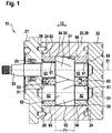
- Fig. 1 shows a longitudinal section of a gear machine 10 according to the invention.
- the gear machine 10 comprises a housing 20, which consists of a main body 30; a drive cover 21 and an end cover 22 is composed, which preferably consist of aluminum or gray cast iron.
- the drive and the end cover 21; 22 abut on flat end surfaces at the opposite ends of the main body 30, wherein at the end faces O-rings 24 are provided made of an elastomer, so that no pressure fluid can escape from the corresponding joint.
- the drive and the end cover 21; 22 are aligned over cylindrical pins 26 relative to the main body 30 and screwed (not shown) with these bolts firmly.
- gears 50 are rotatably received with respect to an associated axis of rotation 51, wherein the gears 50 mesh with each other in external engagement.
- the said axes of rotation 51 run parallel to a longitudinal direction 12.
- the gears 50 are present helically toothed, but they can also be formed straight toothed.
- the two gears 50 have on both sides of a circular cylindrical bearing pin 52 which is rotatably mounted in a bearing shell 61 made of a sliding bearing material such as brass or bronze, wherein the bearing shell 61 is in turn firmly received in an associated bearing body 60 made of aluminum.
- each bearing pin 52 is associated with a separate bearing body 60, wherein two adjacent bearing body 60 abut each other on flat surfaces and are aligned by means of a cylindrical pin 26 to each other.
- the two above-mentioned bearing body 60 may also be integrally formed.
- the bearing bodies 60 are pressed by the pressure of the pressure fluid, for example hydraulic oil, in the gear machine against the flat side surfaces of the gears 50 to cause a lateral sealing of the gears.
- two sealing levels 71 are defined.
- the pressurized fluid acts in a pressure field on the bearing body 60, which is bounded by an associated axial seal 62.
- One of the bearing journals 52 of a toothed wheel 50 is formed integrally with a drive pin 53 which projects out of the housing 20 through the drive cover 21.
- the corresponding passage opening is sealed with a radial shaft sealing ring 25, so that no pressure fluid can escape.
- the drive pin 53 can be rotatably connected, for example, with the drive shaft of an electric motor (not shown) when the gear machine 10 is operated as a pump.
- the inner circumferential surface 31 of the main body 30 has, prior to the running-in process along the longitudinal direction 12, a constant cross-sectional shape, which is adapted to the circular cylindrical tip diameter of the gears 50 with very little play.
- the pressure equalization bevel 64 at the in Fig. 1 indicate left bearing body 60.
- This pressure compensation chamfer 64 extends on the circumference of the associated gear from the high pressure port in the direction of the low pressure port, where it ends about two pitches before the low pressure port.
- a fluid connection between the tooth chambers of the toothed wheels and the high-pressure connection is established via the pressure equalization bevel, so that the pressure prevails in the high-pressure connection in all tooth chambers which are located in the region of the pressure equalization bevel 64.
- the tooth tips should be in fluid-tight contact with the inner peripheral surface 31 of the main body 30.
- the Druckaus GmbHsfase 64 may be present as shown only on one side of the gears 50, but it may also be provided on both sides of the gears 50. In the latter case is to be considered in helical gears 50 that the two pressure equalization bevels 64 must be designed to have different lengths, so that they end at the same tooth of the associated gear 50.
- Fig. 2 shows the view Fig. 1 without the gears and the bearing bodies.
- a low-pressure port 23 which is in the form of a circular-cylindrical aperture connecting the inner peripheral surface of the main body 30 with its outer peripheral surface so that a pressurized fluid source or sink can be connected there. 180 ° about the longitudinal direction opposite to the main body 20, the high-pressure port is provided which in Fig. 2 is not visible.
- the high-pressure connection is likewise designed in the form of a circular-cylindrical opening, which typically has a smaller diameter than the low-pressure connection 23.
- the inner peripheral surface 31 of the main body 30 has a first portion 32, which in turn is composed of two portions 36, which are adapted to the sprockets, and a connection portion 37.
- the regions 36 are made with a boring bar (not shown) whose axis of rotation coincides with the axis of rotation of the associated gear.
- the drill rod preferably has a single cutting plate whose circular cutting edge rotates on a diameter corresponding to the tip circle diameter of the gears.
- the rapidly rotating boring bar in the longitudinal direction 12 is moved through the main body 30. In this case, a diameter is produced in a first rough section, which is minimally smaller than the final diameter, namely the tip circle diameter of the associated gear.
- the groove 70 according to the invention is produced, for example, with the drill rod for the rough cut.
- the axis of rotation of the drill rod is initially brought to coincide with the axis of rotation of the associated gear, wherein the drill rod is then moved in the longitudinal direction 12 so that the cutting edge is in the region of a sealing plane 71.
- the exact location of the groove 70 is on the comments on the Fig. 3 to 5 directed.
- the rapidly rotating drill rod is moved in the direction of the low-pressure connection 23 transversely to its axis of rotation, so that the cutting edge cuts into the main body 30.
- the groove 70 has a depth of, for example, 0.05 mm, wherein the depth towards the other end steadily decreases to zero.
- the length of the groove 70 results from the diameter on which the cutting edge rotates and the diameter of the region 36. It extends over the material region 76, which is later filled with the burr, and over the marked with No. 70 area, the is arranged exclusively in the first portion 32 of the inner peripheral surface 31 and ends at the associated second portion.
- connection region 37 is provided, which is produced, for example, with a milling cutter.
- the connection region 37 is offset radially outwards relative to the circular-cylindrical regions 36, so that the pressurized fluid can be distributed over the entire width of the housing 20 past the low-pressure or high-pressure connection 23 past the bearing bodies.
- the gear machine 10 is completely assembled. To carry out the inlet process, it is connected to a source of pressurized fluid and to a pressure fluid sink and filled with pressurized fluid, for example hydraulic oil. Subsequently, the gears are rotated so that sets in the gear machine 10, the maximum operating pressure.
- a pump the gears are moved from the outside, for example with an electric motor, in motion, wherein the source of pressurized fluid is a tank and the pressure fluid sink is a throttle connected to the tank.
- the gears are set in motion by the pressure fluid supplied to the high pressure port under pressure.
- the pressure fluid sink is a tank, wherein the pressure fluid source is a pump which sucks pressure fluid from the tank.
- the pressure of the pressurized fluid causes the gears in the region of the low pressure port 23 to be pressed against the inner circumferential surface of the main body 30, wherein material is removed in the second sections 33 there, so that the inner circumferential surface 31 transversely to the longitudinal direction relative to the first section 32 to the outside is.
- the offset mentioned is at the lowest point, for example, 0.05 mm, wherein it gradually decreases in the circumferential direction from the low pressure port to zero.
- the edge 35 of the second portion 33 in the circumferential direction is typically shaped very irregular. Its location depends in particular on the exact dimensions of the components involved within their manufacturing tolerance.
- the length of the groove 70 is chosen so that even with the most unfavorable tolerance position, a small Nutrest in the first portion 32 of the inner peripheral surface 31 of the main body 30 is present.
- Fig. 3 shows a rough schematic partial longitudinal section of the groove 70 in the region of the second portion of the inner peripheral surface 31 of the main body 30 before the run-in process, wherein the position of the cutting plane in Fig. 2 marked with AA.
- the groove 70 is circular when viewed in cross-section, the corresponding radius 75 being 0.8 mm, for example. This radius is defined by the corner radius at the cutting edge of the cutting plate discussed above.
- the width 74 of the groove 70 is for example 0.5 mm, wherein the depth 73 of the groove 70 is for example 0.05 mm.
- the position of the groove 70 is selected so that the sealing plane 71, at which the bearing body 60 and the associated gear 50 sealingly contact, the groove 70 intersects. Since the bearing bodies 60 are minimally movable with the gears 50 within the main body 30 in the longitudinal direction 12, the relative position of the groove 70 with respect to the sealing plane 71 is not exactly predictable. However, the dimensions and tolerances of the corresponding components are determined so that the sealing plane in the best case, the in Fig. 3 left side edge 72a of the groove 70 intersects, passing in the worst case by the center of the groove 70. This ensures in any case that the in Fig. 3 right side edge 72b of the groove 70 is below the gear 50.
- the inner peripheral surface 31 of the main body 30 along the longitudinal direction 12 has a constant cross-sectional shape, so that the bearing body 60 and the associated gear 50 are precisely aligned.
- Fig. 4 shows the view Fig. 3 during the warm-up process.
- the gear 50 by the pressure of the pressurized fluid in Fig. 4 pressed down against the inner peripheral surface 31 of the main body 30.
- the rotational movement of the gear 50 causes a material removal on the main body 30, so that the gear 50 in Fig. 4 relative to the bearing body 60 moves slightly downwards. It arises at the in Fig. 4 right side edge 72b of the groove, which is located below the gear 50, a ridge 77 which is pressed by the gear in the groove 70.
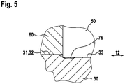
- Fig. 5 shows the view Fig. 3 after the warm-up process is completed.
- a significant offset between the bearing body 60 and the gear 50 is determined, which corresponds to the depth of the second portion 33 of the inner peripheral surface 31 of the main body 30, which is for example 0.05 mm.
- the former groove is now completely filled with the material of the burrs, so that a material region 76 results whose microstructure differs from that of the remaining main body 30.
- This material portion 76 is sealingly against the tooth tips of the gear 50 so that there is no pressure fluid between two adjacent tooth chambers can be replaced.
- the depth of the groove (No. 73 in Fig. 3 ) must be determined by experiment so that the state described above results.
Landscapes
- Engineering & Computer Science (AREA)
- Mechanical Engineering (AREA)
- General Engineering & Computer Science (AREA)
- Rotary Pumps (AREA)
- General Details Of Gearings (AREA)
- Gear Transmission (AREA)
Description
- Die Erfindung betrifft eine Zahnradmaschine gemäß dem Oberbegriff von Anspruch 1.
- Aus der
DE 10 2009 012 853 A1 ist eine Zahnradmaschine bekannt, die als Pumpe oder als Motor ausgebildet sein kann. Die Zahnradmaschine besitzt zwei Zahnräder, die im Außeneingriff miteinander kämmen, wobei deren Drehachsen parallel zu einer Längsrichtung ausgerichtet sind. Die Zahnräder sind von einem Gehäuse umgeben, welches einen Hauptkörper, einen Antriebsdeckel und einen Enddeckel aufweist. Der Hauptkörper weist eine Innenumfangsfläche auf, die entlang der Längsrichtung in einem ersten Abschnitt mit einer konstanten Querschnittsform ausgebildet ist. Diese Querschnittsform ist mit sehr geringem Spiel an den Kopfkreisdurchmesser der genannten Zahnräder angepasst. Weiter ist jedem Zahnrad ein zweiter Abschnitt der Innenumfangsfläche zugeordnet, der auch als Einlaufspur bezeichnet wird. Dieser ist quer zur Längsrichtung gegenüber dem ersten Abschnitt der Innenumfangsfläche nach außen versetzt angeordnet. Bezüglich der Längsrichtung neben wenigstens einem Zahnrad ist wenigstens ein zugeordneter Lagerkörper angeordnet, welcher an der Innenumfangsfläche anliegt, wobei das wenigstens eine Zahnrad drehbar in dem wenigstens einen zugeordneten Lagerkörper gelagert ist. - Das Gehäuse weist einen Hoch- und einen Niederdruckanschluss auf. Wenn die Zahnradmaschine als Pumpe betrieben wird, fließt Druckfluid, beispielsweise Hydrauliköl, vom Niederdruck- zum Hochdruckanschluss, wobei die Zahnräder beispielsweise durch einen Elektromotor in Drehbewegung versetzt werden. Wenn die Zahnradmaschine als Motor betrieben wird, fließt das Druckfluid vom Hochdruckanschluss zum Niederdruckanschluss, wodurch die Zahnräder in Drehbewegung versetzt werden.
- Bei der Herstellung wird die Zahnradmaschine einem Einlaufprozess unterzogen. Dabei wird eine Zahnradmaschine hergestellt, bei der die zweiten Abschnitte der Innenumfangsfläche des Hauptkörpers noch fluchtend zu dem ersten Abschnitt ausgebildet sind, d.h. die Innenumfangsfläche weist entlang der Längsrichtung überall eine konstante Querschnittsform auf. Beim Einlaufen wird die Zahnradmaschine mit Druckfluid gefüllt, wobei sie an eine Druckfluidquelle und an eine Druckfluidsenke angeschlossen wird. Die Zahnräder werden nun in Drehbewegung versetzt, so dass sich in der Zahnradmaschine der maximale Betriebsdruck ausbildet. Dies führt dazu, dass die Zahnräder vom Druck des Druckfluids im Bereich des Niederdruckanschlusses gegen die Innenumfangsfläche des Hauptkörpers gerückt werden. Die Relativbewegung zwischen den Zahnrädern und dem Hauptkörper bewirkt, dass an der Innenumfangsfläche des Hauptkörpers Material abgetragen wird, so dass sich die zweiten Abschnitte der Innenumfangsfläche ausbilden, die gegenüber den ersten Abschnitten radial nach außen versetzt sind. Hierbei ist anzumerken, dass die Zahnräder typischerweise aus gehärtetem Stahl bestehen, wobei der Hauptkörper aus Aluminium oder Grauguss besteht.
- Bei dem Einlaufprozess ergibt sich das Problem, dass an den Seitenrändern der zweiten Abschnitte bzw. der Einlaufspuren Grate entstehen. Diese drücken sich zwischen die Seitenflächen der Zahnräder und den daran anliegenden Lagerkörpern, so dass diese Teile nicht mehr optimal dichtend aneinander anliegen. Insbesondere bei schräg verzahnten Zahnrädern sind die genannten Grate oft nur auf einer Seite der zweiten Abschnitte zu beobachten.
- Weiter wird auf
DE 19 63 981 A1 verwiesen, welche die Merkmale des Oberbegriffs von Anspruch 1 offenbart, wobei insbesondere der Einlaufprozess einer Zahnradpumpe beschrieben ist. - Die Aufgabe der Erfindung besteht darin, die dichtende Anlage des Lagerkörpers an den Zahnrädern auch nach dem Einlaufprozess sicherzustellen. Diese Aufgabe wird durch das Verfahren nach Anspruch 11 gelöst, wobei als Verfahrensergebnis eine Zahnradmaschine nach Anspruch 1 entsteht.
- Demnach wird an der Innenumfangsfläche des Hauptkörpers vor dem Einlaufprozess eine Nut vorgesehen, die den genannten Grat aufnehmen kann. Im Bereich der zweiten Abschnitte der Innenumfangsfläche wird die Nut während des Einlaufprozesses teilweise wieder abgetragen, wobei der verbleibende Rest der Nut mit dem Material der Grate vollständig aufgefüllt wird. Im Ergebnis werden die Grate nur noch in die erfindungsgemäße Nut gedrückt, wobei sie nicht mehr zwischen den Lagerkörper und die zugeordnete Zahnradmaschine gelangen können. An der fertigen Zahnradmaschine ist die in den zweiten Abschnitten ursprünglich vorhandene Nut kaum noch zu erkennen.
- Nur die Abschnitte der Nut, die in den ersten Abschnitt der Innenumfangsfläche des Hauptkörpers hineinragen und daher vom Einlaufprozess nicht erfasst werden, sind an der fertigen Zahnradpumpe noch zu erkennen. Hierbei ist anzumerken, dass sich die Lage des Randes der zweiten Abschnitte der Innenumfangsfläche des Hauptkörpers in Umfangsrichtung nicht genau vorherbestimmen lässt, da seine Lage von den genauen Maßen der beteiligten Bauteile innerhalb ihrer Herstellungstoleranz abhängt. Die erfindungsgemäße Nut wird daher vor dem Einlaufen vorzugsweise so lange ausgeführt, dass sie sich auch bei ungünstigster Toleranzlage über die gesamte Länge des späteren zweiten Abschnitts der Innenumfangsfläche erstreckt, da am gesamten Seitenrand des zweiten Abschnitts die schädlichen Grate entstehen können.
- In den abhängigen Ansprüchen sind vorteilhafte Weiterbildungen und Verbesserungen der Erfindung angegeben.
- In Verlängerung jeder Nut kann im zugeordneten zweiten Abschnitt der Innenumfangsfläche ein geradliniger Materialbereich vorgesehen sein, der gegenüber dem verbleibenden Hauptkörper eine veränderte Gefügestruktur aufweist. Bei dem Materialbereich handelt es sich um die in den zweiten Abschnitten vor dem Einlaufprozess vorhandene Nut, die nach dem Einlaufprozess vollständig mit dem während des Einlaufprozesses entstehenden Grat aufgefüllt ist. Das Gratmaterial wird dabei erheblichen plastischen Verformungen ausgesetzt, so dass sich seine Gefügestruktur erheblich ändert. Diese veränderte Gefügestruktur kann man beispielsweise nachweisen, indem man den Hauptkörper quer zum genannten Materialbereich aufschneidet, wobei man die Schnittfläche poliert und anäzt. Wenn man nun den Materialbereich mit einem Mikroskop betrachtet, kann man die Gefügeunterschiede zwischen dem Materialbereich und dem verbleibenden Hauptkörper leicht erkennen.
- Die Nut kann quer zur Längsrichtung verlaufen, damit sie in Flucht mit dem Seitenrand des zugeordneten zweiten Abschnitts der Innenumfangsfläche des Hauptkörpers angeordnet ist.
- Die Tiefe der Nut an dem Ende, das dem zweiten Abschnitt der Innenumfangsfläche zugeordnet ist, kann am größten sein, wobei die Tiefe der Nut zum gegenüberliegenden Ende hin stetig auf Null abnimmt. Wie bereits angesprochen, nimmt auch die Tiefe der zweiten Abschnitte bzw. der Einlaufspuren von einer Maximaltiefe stetig auf Null ab. Die Tiefe der zweiten Abschnitte ist im Wesentlichen proportional zu dem Volumen, welches der Grat an der betreffenden Stelle hat. Damit das Volumen der Nut immer genau so groß ist, dass es das Volumen des Grates aufnehmen kann, wird die Tiefe der Nut wie oben vorgeschlagen ausgebildet.
- Die Nut kann eine konstante kreisförmige Querschnittsform aufweisen. Eine derartige Nut kann leicht mit einer Schneidplatte hergestellt werden, deren Schneidkante einen Eckenradius aufweist. Dieser Eckenradius kann beispielsweise 0,8 mm betragen. Versuche der Anmelderin haben gezeigt, dass eine derartige Nut das gewünschte Ergebnis liefert. Die entsprechende Nut nimmt den Grat so auf, dass an der fertigen Zahnradpumpe in den zweiten Abschnitten der Innenumfangsfläche des Hauptkörpers keine Reste der vor dem Einlaufen vorhandenen Nut stehen bleiben.
- Die Länge der wenigstens einen Nut kann zwischen 5 mm und 50 mm betragen. Dieser Längenbereich entspricht in etwa der Längentoleranz der zweiten Abschnitte in Umfangsrichtung um die Zahnräder.
- Die wenigstens eine Nut kann in dem Bereich angeordnet sein, in dem sich der wenigstens eine Lagerkörper und das zugeordnete Zahnrad berühren. In diesem Bereich entsteht der oben angesprochene schädliche Grat am Hauptkörper. Wenn die Nut im vorgeschlagenen Bereich angeordnet ist, kann sich das Material der Grate besonders leicht in die Nut hineindrücken und diese auffüllen.
- Der wenigstens eine Lagerkörper und das zugeordnete Zahnrad können sich in einer Dichtebene berühren, welche senkrecht zur Längsrichtung ausgerichtet ist, wobei die Dichtebene die Nut schneidet. Es ist üblich, dass sich die Lagerkörper und die zugeordneten Zahnräder in einer Dichtebene berühren. Wenn diese Dichtebene die erfindungsgemäße Nut schneidet, kann sich das Material der Grate besonders leicht in die Nut hineindrücken und diese auffüllen. Die Dichteebene schneidet die Nut auch dann im obigen Sinne, wenn sie genau mit einem Seitenrand der Nut zusammenfällt.
- Die Nut kann zu mehr als der Hälfte ihrer Breite auf der Seite der Dichtebene angeordnet sein, welche dem Zahnrad zugeordnet ist. Hierdurch wird sichergestellt, dass einer der beiden Seitenränder der Nut unterhalb des Zahnrades angeordnet ist. Dieser Seitenrand ist der Ort, an dem der Grat entstehen soll, damit sein Material leicht in die Nut hineingerückt werden und diese auffüllen kann.
- Der wenigstens eine Lagerkörper kann eine Druckausgleichsfase aufweisen, die sowohl dem zugeordneten Zahnrad als auch der Innenumfangsfläche des Hauptkörpers gegenüber liegt, wobei die Nut und die Druckausgleichsfase zumindest teilweise, vorzugsweise vollständig, in unterschiedlichen Bereichen am Umfang des zugeordneten Zahnrades angeordnet sind. Die Druckausgleichsfase steht dabei vorzugsweise in Fluidverbindung mit dem Hochdruckanschluss der Zahnradmaschine. Dies hat zur Folge, dass im Bereich der Druckausgleichsfase überall der Druck am Hochdruckanschluss in den Zahnzwischenräumen des zugeordneten Zahnrades wirkt. Dies hat wiederum zur Folge, dass die Zahnräder beim Einlaufen der Zahnradmaschine mit einer gut vorausberechenbaren Kraft gegen die Innenumfangsfläche des Hauptkörpers gedrückt werden. In der Folge lässt sich die Länge der zweiten Abschnitte in Umfangsrichtung um die Zahnräder in einer praktikablen Größenordnung vorherbestimmen. Diese Funktion der Druckausgleichsfase soll durch die erfindungsgemäße Nut möglichst wenig gestört werden.
- Die Erfindung wird im Folgenden anhand der beigefügten Zeichnungen näher erläutert. Es stellt dar:
- Fig. 1
- einen Längsschnitt einer erfindungsgemäßen Zahnradmaschine;
- Fig. 2
- die Ansicht nach
Fig. 1 ohne die Zahnräder und die Lagerkörper; - Fig. 3
- einen grobschematischen Teillängsschnitt der Nut im Bereich des zweiten Abschnitts vor dem Einlaufprozess;
- Fig. 4
- die Ansicht nach
Fig. 3 während des Einlaufprozesses; und - Fig. 5
- die Ansicht nach
Fig. 3 , nachdem der Einlaufprozess abgeschlossen ist. -
Fig. 1 zeigt einen Längsschnitt einer erfindungsgemäßen Zahnradmaschine 10. Die Zahnradmaschine 10 umfasst ein Gehäuse 20, das aus einem Hauptkörper 30; einem Antriebsdeckel 21 und einem Enddeckel 22 zusammengesetzt ist, die vorzugsweise aus Aluminium oder aus Grauguss bestehen. Der Antriebs- und der Enddeckel 21; 22 liegen an ebenen Stirnflächen an den gegenüberliegenden Enden des Hauptkörpers 30 an, wobei an den Stirnflächen O-Ringe 24 aus einem Elastomer vorgesehen sind, damit aus der entsprechenden Fuge kein Druckfluid austreten kann. Der Antriebs- und der Enddeckel 21; 22 sind über Zylinderstifte 26 relativ zum Hauptkörper 30 ausgerichtet und über (nicht dargestellte) Schraubbolzen mit diesen fest verschraubt. - In dem Gehäuse 20 sind zwei Zahnräder 50 bezüglich einer zugeordneten Drehachse 51 drehbar aufgenommen, wobei die Zahnräder 50 im Außeneingriff miteinander kämmen. Die genannten Drehachsen 51 verlaufen parallel zu einer Längsrichtung 12. Die Zahnräder 50 sind vorliegend schräg verzahnt, sie können aber auch gerade verzahnt ausgebildet sein.
- Die beiden Zahnräder 50 weisen auf beiden Seiten einen kreiszylindrischen Lagerzapfen 52 auf, der in einer Lagerschale 61 aus einem Gleitlagerwerkstoff wie Messing oder Bronze, drehbar gelagert ist, wobei die Lagerschale 61 wiederum in einem zugeordneten Lagerkörper 60 aus Aluminium fest aufgenommen ist. Bei der vorliegenden Ausführungsform ist jedem Lagerzapfen 52 ein gesonderter Lagerkörper 60 zugeordnet, wobei zwei benachbarte Lagerkörper 60 an ebenen Flächen aneinander anliegen und mittels eines Zylinderstiftes 26 zueinander ausgerichtet sind. Die beiden vorstehend genannten Lagerkörper 60 können auch einstückig ausgebildet sein. Die Lagerkörper 60 werden von dem Druck des Druckfluids, beispielsweise Hydrauliköl, in der Zahnradmaschine gegen die ebenen Seitenflächen der Zahnräder 50 gedrückt, um eine seitliche Abdichtung der Zahnräder zu bewirken. Hierdurch werden zwei Dichtebenen 71 definiert. Das Druckfluid wirkt dabei in einem Druckfeld auf den Lagerkörper 60 ein, welches von einer zugeordneten Axialdichtung 62 begrenzt wird.
- Einer der Lagerzapfen 52 eines Zahnrades 50 ist einstückig mit einem Antriebszapfen 53 ausgebildet, der durch den Antriebsdeckel 21 hindurch aus dem Gehäuse 20 herausragt. Die entsprechende Durchtrittsöffnung ist mit einem Radialwellendichtring 25 dicht verschlossen, so dass kein Druckfluid austreten kann. Der Antriebszapfen 53 kann beispielsweise mit der Antriebswelle eines (nicht dargestellten) Elektromotors drehfest verbunden werden, wenn die Zahnradmaschine 10 als Pumpe betrieben wird.
- Die Innenumfangsfläche 31 des Hauptkörpers 30 weist vor dem Einlaufprozess entlang der Längsrichtung 12 eine konstante Querschnittsform auf, die mit sehr geringem Spiel an den kreiszylindrischen Kopfkreisdurchmesser der Zahnräder 50 angepasst ist. Weiter ist auf die Druckausgleichsfase 64 an den in
Fig. 1 linken Lagerkörper 60 hinzuweisen. Diese Druckausgleichsfase 64 erstreckt sich am Umfang des zugeordneten Zahnrades vom Hochdruckanschluss in Richtung des Niederdruckanschlusses, wobei sie etwa zwei Zahnteilungen vor dem Niederdruckanschluss endet. Über die Druckausgleichsfase wird eine Fluidverbindung zwischen den Zahnkammern der Zähnräder und dem Hochdruckanschluss hergestellt, so dass in allen Zahnkammern, die sich im Bereich der Druckausgleichsfase 64 befinden, der Druck am Hochdruckanschluss herrscht. In dem Bereich in der Nähe des Niederdruckanschlusses, in dem keine Druckausgleichsfase 64 vorhanden ist, sollen die Zahnköpfe fluiddicht an der Innenumfangsfläche 31 des Hauptkörpers 30 anliegen. Die Druckausgleichsfase 64 kann wie vorliegend dargestellt nur auf einer Seite der Zahnräder 50 vorhanden sein, sie kann aber auch auf beiden Seiten der Zahnräder 50 vorgesehen sein. Im letzteren Fall ist bei schräg verzahnten Zahnrädern 50 zu berücksichtigen, dass die beiden Druckausgleichsfasen 64 unterschiedlich lang ausgebildet sein müssen, damit sie am gleichen Zahn des zugeordneten Zahnrades 50 enden. -
Fig. 2 zeigt die Ansicht nachFig. 1 ohne die Zahnräder und die Lagerkörper. An dem Hauptkörper 30 ist ein Niederdruckanschluss 23 vorgesehen, der in Form eines kreiszylindrischen Durchbruchs ausgebildet ist, der die Innenumfangsfläche des Hauptkörpers 30 mit seiner Außenumfangsfläche verbindet, so dass dort eine Druckfluidquelle oder -senke angeschlossen werden kann. 180° um die Längsrichtung gegenüberliegend am Hauptkörper 20 ist der Hochdruckanschluss vorgesehen, der inFig. 2 nicht sichtbar ist. Der Hochdruckanschluss ist ebenfalls in Form eines kreiszylindrischen Durchbruchs ausgebildet, der typischerweise einen kleineren Durchmesser aufweist als der Niederdruckanschluss 23. - Die Innenumfangsfläche 31 des Hauptkörpers 30 weist einen ersten Abschnitt 32 auf, der wiederum aus zwei Bereichen 36, die an die Zähnräder angepasst sind, und einem Anschlussbereich 37 zusammengesetzt ist. Die Bereiche 36 werden mit einer (nicht dargestellten) Bohrstange hergestellt, deren Drehachse mit der Drehachse des zugeordneten Zahnrades zusammenfällt. Die Bohrstange weist vorzugsweise eine einzige Schneidplatte auf, deren kreisrunde Schneidkante auf einem Durchmesser umläuft, der dem Kopfkreisdurchmesser der Zahnräder entspricht. Zur Herstellung der Bereiche 36 wird die sich schnell drehende Bohrstange in Längsrichtung 12 durch den Hauptkörper 30 bewegt. Dabei wird in einem ersten Grobschnitt ein Durchmesser hergestellt, der minimal kleiner als der Enddurchmesser, nämlich der Kopfkreisdurchmesser des zugeordneten Zahnrades, ist. Hierbei wird eine große Materialmenge in kurzer Zeit abgetragen. In dem anschließenden Feinschnitt wird der etwas größere Enddurchmesser mit einer vergleichsweise langsamen Vorschubbewegung in Längsrichtung 12 hergestellt, so dass die Bereiche 37 eine sehr hohe Genauigkeit aufweisen. Anschließend wird beispielsweise mit der Bohrstange für den Grobschnitt die erfindungsgemäße Nut 70 hergestellt. Hierfür wird die Drehachse der Bohrstange anfangs mit der Drehachse des zugeordneten Zahnrades zur Deckung gebracht, wobei die Bohrstange anschließend in Längsrichtung 12 so verfahren wird, dass sich die Schneidkante im Bereich einer Dichtebene 71 befindet. Zur genauen Lage der Nut 70 wird auf die Ausführungen zu den
Fig. 3 bis 5 verwiesen. - Anschließend wird die sich schnell drehende Bohrstange in Richtung des Niederdruckanschlusses 23 quer zu ihrer Drehachse verfahren, so dass die Schneidkante in den Hauptkörper 30 einschneidet. Im Bereich des Niederdruckanschlusses hat die Nut 70 eine Tiefe von beispielsweise 0,05 mm, wobei die Tiefe zum anderen Ende hin stetig auf Null abnimmt. Die Länge der Nut 70 ergibt sich aus dem Durchmesser, auf dem die Schneidkante umläuft und dem Durchmesser des Bereichs 36. Sie erstreckt sich über den Materialbereich 76, der später mit dem Grat aufgefüllt wird, und über den mit Nr. 70 gekennzeichneten Bereich, der ausschließlich im ersten Abschnitt 32 der Innenumfangsfläche 31 angeordnet ist und am zugeordneten zweiten Abschnitt endet.
- Zwischen den Bereichen 36 ist der Anschlussbereich 37 vorgesehen, der beispielsweise mit einem Fräser hergestellt wird. Der Anschlussbereich 37 ist gegenüber den kreiszylindrischen Bereichen 36 nach radial außen versetzt, so dass sich das Druckfluid vom Nieder- bzw. Hochdruckanschluss 23 an den Lagerkörpern vorbei auf die gesamte Breite des Gehäuses 20 verteilen kann.
- Nachdem die vorstehend beschriebenen Herstellungsschritte durchgeführt wurden, wird die Zahnradmaschine 10 komplett zusammengebaut. Zur Durchführung des Einlaufprozesses wird sie an eine Druckfluidquelle und an eine Druckfluidsenke angeschlossen und mit Druckfluid, beispielsweise Hydrauliköl, gefüllt. Anschließend werden die Zahnräder so in Drehbewegung versetzt, dass sich in der Zahnradmaschine 10 der maximale Betriebsdruck einstellt. Bei einer Pumpe werden die Zahnräder von außen, beispielsweise mit einem Elektromotor, in Bewegung versetzt, wobei die Druckfluidquelle ein Tank und die Druckfluidsenke eine mit dem Tank verbundene Drossel ist. Bei einem Motor werden die Zahnräder durch das am Hochdruckanschluss unter Druck zugeführte Druckfluid in Bewegung versetzt. Die Druckfluidsenke ist dabei ein Tank, wobei die Druckfluidquelle eine Pumpe ist, welche Druckfluid aus dem Tank ansaugt.
- Der Druck des Druckfluids bewirkt, dass die Zahnräder im Bereich des Niederdruckanschlusses 23 gegen die Innenumfangsfläche des Hauptkörpers 30 gedrückt werden, wobei in den dortigen zweiten Abschnitten 33 Material abgetragen wird, so dass die Innenumfangsfläche 31 quer zur Längsrichtung gegenüber dem ersten Abschnitt 32 nach außen versetzt ist. Der genannte Versatz beträgt an der tiefsten Stelle beispielsweise 0,05 mm, wobei er in Umfangsrichtung vom Niederdruckanschluss weg stetig auf Null abnimmt. Der Rand 35 des zweiten Abschnitts 33 in Umfangsrichtung ist typischerweise sehr unregelmäßig geformt. Seine Lage ist insbesondere von den genauen Maßen der beteiligten Bauteile innerhalb ihrer Herstellungstoleranz abhängig. Die Länge der Nut 70 wird dabei so gewählt, dass auch bei ungünstigster Toleranzlage ein kleiner Nutrest im ersten Abschnitt 32 der Innenumfangsfläche 31 des Hauptkörpers 30 vorhanden ist.
-
Fig. 3 zeigt einen grobschematischen Teillängsschnitt der Nut 70 im Bereich des zweiten Abschnitts der Innenumfangsfläche 31 des Hauptkörpers 30 vor dem Einlaufprozess, wobei die Lage der Schnittebene inFig. 2 mit A-A gekennzeichnet ist. Die Nut 70 ist im Querschnitt betrachtet kreisrund ausgebildet, wobei der entsprechende Radius 75 beispielsweise 0,8 mm beträgt. Dieser Radius wird durch den Eckenradius an der Schneidkante der oben angesprochenen Schneidplatte definiert. - Die Breite 74 der Nut 70 beträgt beispielsweise 0,5 mm, wobei die Tiefe 73 der Nut 70 beispielsweise 0,05 mm beträgt. Die Lage der Nut 70 ist so gewählt, dass die Dichtebene 71, an der sich der Lagerkörper 60 und das zugeordneten Zahnrad 50 dichtend berühren, die Nut 70 schneidet. Da die Lagerkörper 60 mit den Zahnrädern 50 innerhalb des Hauptkörpers 30 in Längsrichtung 12 minimal beweglich sind, ist die Relativlage der Nut 70 gegenüber der Dichtebene 71 nicht exakt vorhersehbar. Die Abmessungen und Toleranzen der entsprechenden Bauteile sind jedoch so festgelegt, dass die Dichtebene im günstigsten Fall den in
Fig. 3 linken Seitenrand 72a der Nut 70 schneidet, wobei sie im ungünstigsten Fall durch die Mitte der Nut 70 verläuft. Damit ist in jedem Fall sichergestellt, dass sich der inFig. 3 rechte Seitenrand 72b der Nut 70 unterhalb des Zahnrades 50 befindet. - Vor dem Einlaufen weist die Innenumfangsfläche 31 des Hauptkörpers 30 entlang der Längsrichtung 12 eine konstante Querschnittsform auf, so dass der Lagerkörper 60 und das zugeordnete Zahnrad 50 genau in einer Flucht angeordnet sind.
-
Fig. 4 zeigt die Ansicht nachFig. 3 während des Einlaufprozesses. Dabei wird das Zahnrad 50 durch den Druck des Druckfluids inFig. 4 nach unten gegen die Innenumfangsfläche 31 des Hauptkörpers 30 gedrückt. Die Drehbewegung des Zahnrades 50 bewirkt einen Materialabtrag am Hauptkörper 30, so dass sich das Zahnrad 50 inFig. 4 gegenüber dem Lagerkörper 60 etwas nach unten verschiebt. Dabei entsteht an dem inFig. 4 rechten Seitenrand 72b der Nut, der sich unterhalb des Zahnrades 50 befindet, ein Grat 77, der von dem Zahnrad in die Nut 70 gedrückt wird. -
Fig. 5 zeigt die Ansicht nachFig. 3 , nachdem der Einlaufprozess abgeschlossen ist. Nunmehr ist ein deutlicher Versatz zwischen dem Lagerkörper 60 und dem Zahnrad 50 festzustellen, welcher der Tiefe des zweiten Abschnittes 33 der Innenumfangsfläche 31 des Hauptkörpers 30 entspricht, die beispielsweise 0,05 mm beträgt. Die ehemalige Nut ist nunmehr vollständig mit dem Material der Grate aufgefüllt, so dass sich ein Materialbereich 76 ergibt, dessen Gefügestruktur sich von der des verbleibenden Hauptkörpers 30 unterscheidet. Dieser Materialbereich 76 liegt dichtend an den Zahnköpfen des Zahnrades 50 an, so dass dort kein Druckfluid zwischen zwei benachbarten Zahnkammern ausgetauscht werden kann. Die Tiefe der Nut (Nr. 73 inFig. 3 ) muss durch Versuch so ermittelt werden, dass sich der vorstehend beschriebene Zustand ergibt. -
- 10
- Zahnradmaschine
- 12
- Längsrichtung
- 20
- Gehäuse
- 21
- Antriebsdeckel
- 22
- Enddeckel
- 23
- Niederdruckanschluss
- 24
- O-Ring
- 25
- Radialwellendichtring
- 26
- Zylinderstift
- 30
- Hauptkörper
- 31
- Innenumfangsfläche
- 32
- erster Abschnitt
- 33
- zweiter Abschnitt
- 34
- Seitenrand eines zweiten Abschnitts
- 35
- Rand eines zweiten Abschnitts in Umfangsrichtung
- 36
- an die Zahnräder angepasster Bereich des ersten Abschnitts
- 37
- Anschlussbereich des ersten Abschnitts
- 50
- Zahnrad
- 51
- Drehachse des Zahnrades
- 52
- Lagerzapfen
- 53
- Antriebszapfen
- 60
- Lagerkörper
- 61
- Lagerschale
- 62
- Axialdichtung
- 63
- Zylinderstift
- 64
- Druckausgleichsfase
- 70
- Nut
- 71
- Dichtebene
- 72a
- erster Seitenrand der Nut
- 72b
- zweiter Seitenrand der Nut
- 73
- Tiefe der Nut
- 74
- Breite der Nut
- 75
- Radius der Querschnittsform der Nut
- 76
- Materialbereich
- 77
- Grat
Claims (11)
- Zahnradmaschine (10), insbesondere Pumpe oder Motor, mit wenigstens zwei Zahnrändern (50), die im Außeneingriff miteinander kämmen, wobei deren Drehachsen (51) parallel zu einer Längsrichtung (12) ausgerichtet sind, wobei die Zahnräder (50) von einem Gehäuse (20) umgeben sind, welches einen Hauptkörper (30) umfasst, wobei der Hauptkörper (30) eine Innenumfangsfläche (31) mit einem ersten Abschnitt (32) aufweist, der entlang der Längsrichtung (12) mit einer konstanten Querschnittsform ausgebildet ist, wobei jedem Zahnrad (50) ein zweiter Abschnitt (33) der genannten Innenumfangsfläche (31) zugeordnet ist, der quer zur Längsrichtung (12) gegenüber dem ersten Abschnitt (32) nach außen versetzt angeordnet ist, wobei in Längsrichtung (12) neben wenigstens einem Zahnrad (50) wenigstens ein zugeordneter Lagerkörper (60) angeordnet ist, welcher an der genannten Innenumfangsfläche (31) anliegt, wobei das wenigstens eine Zahnrad (50) in dem wenigstens einen zugeordneten Lagerkörper (60) drehbar gelagert ist,dadurch gekennzeichnet, dass an der genannten Innenumfangsfläche (31) im ersten Abschnitt (32) wenigstens eine geradlinige Nut (70) vorgesehen ist, welche an einem zugeordneten zweiten Abschnitt (33) endet.
- Zahnradmaschine nach Anspruch 1,wobei in Verlängerung jeder Nut (70) im zugeordneten zweiten Abschnitt (33) der Innenumfangsfläche ein geradliniger Materialbereich (76) vorgesehen ist, der gegenüber dem verbleibenden Hauptkörper (30) eine veränderte Gefügestruktur aufweist.
- Zahnradmaschine nach einem der vorstehenden Ansprüche,wobei die Nut (70) quer zur Längsrichtung (12) verläuft.
- Zahnradmaschine nach einem der vorstehenden Ansprüche,wobei die Tiefe (73) der Nut (70) an dem Ende, das dem zweiten Abschnitt (33) der Innenumfangsfläche (31) zugeordnet ist, am größten ist, wobei die Tiefe (73) der Nut (70) zum gegenüberliegenden Ende hin stetig auf Null abnimmt.
- Zahnradmaschine nach einem der vorstehenden Ansprüche,wobei die Nut (70) eine konstante kreisförmige Querschnittsform aufweist.
- Zahnradmaschine nach einem der vorstehenden Ansprüche,wobei die Länge der wenigstens einen Nut (70) zwischen 5 mm und 50 mm beträgt.
- Zahnradmaschine nach einem der vorstehenden Ansprüche,wobei die wenigstens eine Nut (70) in dem Bereich angeordnet ist, in dem sich der wenigstens eine Lagerkörper (60) und das zugeordnete Zahnrad (50) berühren.
- Zahnradmaschine nach Anspruch 7,wobei sich der wenigstens eine Lagerkörper (60) und das zugeordnete Zahnrad (50) in einer Dichtebene (71) berühren, welche senkrecht zur Längsrichtung (12) ausgerichtet ist, wobei die Dichtebene (71) die Nut (70) schneidet.
- Zahnradmaschine nach Anspruch 8,wobei die Nut (70) zu mehr als der Hälfte ihrer Breite (74) auf der Seite der Dichtebene (71) angeordnet ist, welche dem Zahnrad (50) zugeordnet ist.
- Zahnradmaschine nach einem der vorstehenden Ansprüche,wobei der wenigstens eine Lagerkörper (60) eine Druckausgleichsfase (64) aufweist, die sowohl dem zugeordneten Zahnrad (50) als auch der Innenumfangsfläche (31) des Hauptkörpers (30) gegenüber liegt, wobei die Nut (70) und die Druckausgleichsfase (64) zumindest teilweise, vorzugsweise vollständig, in unterschiedlichen Bereichen am Umfang des zugeordneten Zahnrades (50) angeordnet sind.
- Verfahren zur Herstellung einer Zahnradmaschine (10) nach einem der vorstehenden Ansprüche, umfassend folgende Schritte in der angegebenen Reihenfolge:- Bereitstellen einer Zahnradmaschine (10) mit wenigstens zwei Zahnrändern (50), die im Außeneingriff miteinander kämmen, wobei deren Drehachsen (51) parallel zu einer Längsrichtung (12) ausgerichtet sind, wobei die Zahnräder (50) von einem Gehäuse (20) umgeben sind, welches einen Hauptkörper (30) umfasst, wobei der Hauptkörper (30) eine Innenumfangsfläche (31) mit einem ersten Abschnitt (32) aufweist, der entlang der Längsrichtung (12) mit einer konstanten Querschnittsform ausgebildet ist, wobei jedem Zahnrad (50) ein zweiter Abschnitt (33) der genannten Innenumfangsfläche (31) zugeordnet ist, der fluchtend mit dem ersten Abschnitt (32) ausgebildet ist, wobei in Längsrichtung (12) neben wenigstens einem Zahnrad (50) wenigstens ein zugeordneter Lagerkörper (60) angeordnet ist, welcher an der genannten Innenumfangsfläche (31) anliegt, wobei das wenigstens eine Zahnrad (50) in dem wenigstens einen zugeordneten Lagerkörper (60) drehbar gelagert ist, wobei an der genannten Innenumfangsfläche (31) im ersten Abschnitt (32) wenigstens eine geradlinige Nut (70) vorgesehen ist, welche sich in den zugeordneten zweiten Abschnitt (33) hinein erstreckt;- Anschließen der Zahnradmaschine (10) an eine Druckfluidquelle und eine Druckfluidsenke und Befüllen der Zahnradmaschine (10) mit Druckfluid;- Drehen der wenigstens zwei Zahnräder (50), so dass das Druckfluid den maximalen Betriebsdruck aufweist, wobei durch die Zahnräder (50) Material an der Innenumfangsfläche (31) des Hauptkörpers (30) abgetragen wird, um die zweiten Abschnitte (33) der Innenumfangsfläche (31) auszuformen.
Applications Claiming Priority (1)
| Application Number | Priority Date | Filing Date | Title |
|---|---|---|---|
| DE102012217400.1A DE102012217400A1 (de) | 2012-09-26 | 2012-09-26 | Zahnradmaschine mit einer Nut zur Aufnahme eines Einlaufgrates |
Publications (3)
| Publication Number | Publication Date |
|---|---|
| EP2713052A2 EP2713052A2 (de) | 2014-04-02 |
| EP2713052A3 EP2713052A3 (de) | 2017-06-14 |
| EP2713052B1 true EP2713052B1 (de) | 2019-02-27 |
Family
ID=49123640
Family Applications (1)
| Application Number | Title | Priority Date | Filing Date |
|---|---|---|---|
| EP13181923.7A Not-in-force EP2713052B1 (de) | 2012-09-26 | 2013-08-28 | Zahnradmaschine mit einer Nut zur Aufnahme eines Einlaufgrates |
Country Status (2)
| Country | Link |
|---|---|
| EP (1) | EP2713052B1 (de) |
| DE (1) | DE102012217400A1 (de) |
Family Cites Families (5)
| Publication number | Priority date | Publication date | Assignee | Title |
|---|---|---|---|---|
| DE1963981A1 (de) * | 1968-12-27 | 1970-07-16 | Plessey Co Ltd | Selbstspurende Zahnradpumpe |
| NL7307185A (de) * | 1972-09-08 | 1974-03-12 | ||
| JPS55101786A (en) * | 1979-01-26 | 1980-08-04 | Kayaba Ind Co Ltd | Construction of body bore in gear pump or motor |
| JP4075359B2 (ja) * | 2001-11-22 | 2008-04-16 | 株式会社島津製作所 | 歯車ポンプ又はモータ |
| DE102009012853A1 (de) | 2009-03-12 | 2010-09-16 | Robert Bosch Gmbh | Hydraulische Zahnradmaschine |
-
2012
- 2012-09-26 DE DE102012217400.1A patent/DE102012217400A1/de not_active Withdrawn
-
2013
- 2013-08-28 EP EP13181923.7A patent/EP2713052B1/de not_active Not-in-force
Non-Patent Citations (1)
| Title |
|---|
| None * |
Also Published As
| Publication number | Publication date |
|---|---|
| EP2713052A2 (de) | 2014-04-02 |
| DE102012217400A1 (de) | 2014-03-27 |
| EP2713052A3 (de) | 2017-06-14 |
Similar Documents
| Publication | Publication Date | Title |
|---|---|---|
| EP2913561B1 (de) | Motor-Planetengetriebe-Anordnung und Verfahren zum Verbinden eines Motors mit einem Planetengetriebe zur Herstellung einer Motor-Planetengetriebe-Anordnung | |
| DE2818332A1 (de) | Verfahren zur herstellung einer antriebswelle mit balligen aussenkeilzaehnen | |
| EP2672119B1 (de) | Zahnradmaschine mit hydrodynamisch und hydrostatisch gelagertem Lagerzapfen | |
| WO2019243123A1 (de) | Hydrodynamisch wirksamer dichtring und drehdurchführung mit einem solchen dichtring | |
| EP3653325B1 (de) | Verfahren zum spanenden erzeugen eines mit einer doppelschräg-verzahnung versehenen zahnrads | |
| EP2711552B1 (de) | Zahnradmaschine mit von der Kreisform abweichendem Niederdruckanschluss | |
| EP1129292B1 (de) | Schnecke für eine exzenterschneckenpumpe oder einen untertagebohrmotor | |
| DE102012206699B4 (de) | Zahnradmaschine mit wannenartiger Vertiefung an der Außenoberfläche des Gehäuses | |
| DE102016207093B4 (de) | Zahnradfluidmaschine | |
| EP1328730B1 (de) | Füllstücklose innenzahnradpumpe | |
| DE102014014575B4 (de) | Untersetzungsgetriebe | |
| DE69709842T2 (de) | Verfahren zum Drehen des Werkstückes während des Abwalzfräsers, und Zahnrad | |
| DE69517646T2 (de) | Differentialvorrichtung | |
| DE102012209775A1 (de) | Zahnradmaschine mit Schneidzahn | |
| DE102005004657A1 (de) | Innenzahnradmaschine | |
| DE102014212255A1 (de) | Außenzahnradmaschine mit Lagerkörpern, die geradlinig gleitbeweglich aneinander abgestützt sind | |
| DE102013202917A1 (de) | Zahnradmaschine mit erhöhter Partikelrobustheit | |
| EP2469091A2 (de) | Gehäuse für eine Außenzahnradmaschine und Außenzahnradmaschine mit Gehäuse | |
| DE2051066A1 (de) | Zahnradsatz | |
| EP0328745B1 (de) | Innenzahnradmaschine | |
| DE69635785T2 (de) | Verfahren und maschine zur herstellung einer genuteten hülse für ein drehschieberventil | |
| EP2713052A2 (de) | Zahnradmaschine mit einer Nut zur Aufnahme eines Einlaufgrates | |
| DE102019212221A1 (de) | Wellgetriebe | |
| DE102015211477A1 (de) | Hydrostatischer Kupplungsaktor | |
| DD213972A5 (de) | Parallel- und innenachsige kreiskolbenmaschine |
Legal Events
| Date | Code | Title | Description |
|---|---|---|---|
| PUAI | Public reference made under article 153(3) epc to a published international application that has entered the european phase |
Free format text: ORIGINAL CODE: 0009012 |
|
| AK | Designated contracting states |
Kind code of ref document: A2 Designated state(s): AL AT BE BG CH CY CZ DE DK EE ES FI FR GB GR HR HU IE IS IT LI LT LU LV MC MK MT NL NO PL PT RO RS SE SI SK SM TR |
|
| AX | Request for extension of the european patent |
Extension state: BA ME |
|
| PUAL | Search report despatched |
Free format text: ORIGINAL CODE: 0009013 |
|
| AK | Designated contracting states |
Kind code of ref document: A3 Designated state(s): AL AT BE BG CH CY CZ DE DK EE ES FI FR GB GR HR HU IE IS IT LI LT LU LV MC MK MT NL NO PL PT RO RS SE SI SK SM TR |
|
| AX | Request for extension of the european patent |
Extension state: BA ME |
|
| RIC1 | Information provided on ipc code assigned before grant |
Ipc: F04C 2/08 20060101ALI20170508BHEP Ipc: F04C 2/18 20060101AFI20170508BHEP |
|
| STAA | Information on the status of an ep patent application or granted ep patent |
Free format text: STATUS: REQUEST FOR EXAMINATION WAS MADE |
|
| 17P | Request for examination filed |
Effective date: 20171214 |
|
| RBV | Designated contracting states (corrected) |
Designated state(s): AL AT BE BG CH CY CZ DE DK EE ES FI FR GB GR HR HU IE IS IT LI LT LU LV MC MK MT NL NO PL PT RO RS SE SI SK SM TR |
|
| RIC1 | Information provided on ipc code assigned before grant |
Ipc: F04C 2/08 20060101ALI20180917BHEP Ipc: F04C 2/18 20060101AFI20180917BHEP |
|
| GRAP | Despatch of communication of intention to grant a patent |
Free format text: ORIGINAL CODE: EPIDOSNIGR1 |
|
| STAA | Information on the status of an ep patent application or granted ep patent |
Free format text: STATUS: GRANT OF PATENT IS INTENDED |
|
| INTG | Intention to grant announced |
Effective date: 20181106 |
|
| GRAS | Grant fee paid |
Free format text: ORIGINAL CODE: EPIDOSNIGR3 |
|
| GRAA | (expected) grant |
Free format text: ORIGINAL CODE: 0009210 |
|
| STAA | Information on the status of an ep patent application or granted ep patent |
Free format text: STATUS: THE PATENT HAS BEEN GRANTED |
|
| AK | Designated contracting states |
Kind code of ref document: B1 Designated state(s): AL AT BE BG CH CY CZ DE DK EE ES FI FR GB GR HR HU IE IS IT LI LT LU LV MC MK MT NL NO PL PT RO RS SE SI SK SM TR |
|
| REG | Reference to a national code |
Ref country code: GB Ref legal event code: FG4D Free format text: NOT ENGLISH |
|
| REG | Reference to a national code |
Ref country code: CH Ref legal event code: EP |
|
| REG | Reference to a national code |
Ref country code: AT Ref legal event code: REF Ref document number: 1101764 Country of ref document: AT Kind code of ref document: T Effective date: 20190315 |
|
| REG | Reference to a national code |
Ref country code: IE Ref legal event code: FG4D Free format text: LANGUAGE OF EP DOCUMENT: GERMAN |
|
| REG | Reference to a national code |
Ref country code: DE Ref legal event code: R096 Ref document number: 502013012272 Country of ref document: DE |
|
| REG | Reference to a national code |
Ref country code: NL Ref legal event code: MP Effective date: 20190227 |
|
| REG | Reference to a national code |
Ref country code: LT Ref legal event code: MG4D |
|
| PG25 | Lapsed in a contracting state [announced via postgrant information from national office to epo] |
Ref country code: SE Free format text: LAPSE BECAUSE OF FAILURE TO SUBMIT A TRANSLATION OF THE DESCRIPTION OR TO PAY THE FEE WITHIN THE PRESCRIBED TIME-LIMIT Effective date: 20190227 Ref country code: NL Free format text: LAPSE BECAUSE OF FAILURE TO SUBMIT A TRANSLATION OF THE DESCRIPTION OR TO PAY THE FEE WITHIN THE PRESCRIBED TIME-LIMIT Effective date: 20190227 Ref country code: PT Free format text: LAPSE BECAUSE OF FAILURE TO SUBMIT A TRANSLATION OF THE DESCRIPTION OR TO PAY THE FEE WITHIN THE PRESCRIBED TIME-LIMIT Effective date: 20190627 Ref country code: LT Free format text: LAPSE BECAUSE OF FAILURE TO SUBMIT A TRANSLATION OF THE DESCRIPTION OR TO PAY THE FEE WITHIN THE PRESCRIBED TIME-LIMIT Effective date: 20190227 Ref country code: NO Free format text: LAPSE BECAUSE OF FAILURE TO SUBMIT A TRANSLATION OF THE DESCRIPTION OR TO PAY THE FEE WITHIN THE PRESCRIBED TIME-LIMIT Effective date: 20190527 Ref country code: FI Free format text: LAPSE BECAUSE OF FAILURE TO SUBMIT A TRANSLATION OF THE DESCRIPTION OR TO PAY THE FEE WITHIN THE PRESCRIBED TIME-LIMIT Effective date: 20190227 |
|
| PG25 | Lapsed in a contracting state [announced via postgrant information from national office to epo] |
Ref country code: IS Free format text: LAPSE BECAUSE OF FAILURE TO SUBMIT A TRANSLATION OF THE DESCRIPTION OR TO PAY THE FEE WITHIN THE PRESCRIBED TIME-LIMIT Effective date: 20190627 Ref country code: BG Free format text: LAPSE BECAUSE OF FAILURE TO SUBMIT A TRANSLATION OF THE DESCRIPTION OR TO PAY THE FEE WITHIN THE PRESCRIBED TIME-LIMIT Effective date: 20190527 Ref country code: RS Free format text: LAPSE BECAUSE OF FAILURE TO SUBMIT A TRANSLATION OF THE DESCRIPTION OR TO PAY THE FEE WITHIN THE PRESCRIBED TIME-LIMIT Effective date: 20190227 Ref country code: LV Free format text: LAPSE BECAUSE OF FAILURE TO SUBMIT A TRANSLATION OF THE DESCRIPTION OR TO PAY THE FEE WITHIN THE PRESCRIBED TIME-LIMIT Effective date: 20190227 Ref country code: GR Free format text: LAPSE BECAUSE OF FAILURE TO SUBMIT A TRANSLATION OF THE DESCRIPTION OR TO PAY THE FEE WITHIN THE PRESCRIBED TIME-LIMIT Effective date: 20190528 Ref country code: HR Free format text: LAPSE BECAUSE OF FAILURE TO SUBMIT A TRANSLATION OF THE DESCRIPTION OR TO PAY THE FEE WITHIN THE PRESCRIBED TIME-LIMIT Effective date: 20190227 |
|
| PG25 | Lapsed in a contracting state [announced via postgrant information from national office to epo] |
Ref country code: IT Free format text: LAPSE BECAUSE OF FAILURE TO SUBMIT A TRANSLATION OF THE DESCRIPTION OR TO PAY THE FEE WITHIN THE PRESCRIBED TIME-LIMIT Effective date: 20190227 Ref country code: SK Free format text: LAPSE BECAUSE OF FAILURE TO SUBMIT A TRANSLATION OF THE DESCRIPTION OR TO PAY THE FEE WITHIN THE PRESCRIBED TIME-LIMIT Effective date: 20190227 Ref country code: AL Free format text: LAPSE BECAUSE OF FAILURE TO SUBMIT A TRANSLATION OF THE DESCRIPTION OR TO PAY THE FEE WITHIN THE PRESCRIBED TIME-LIMIT Effective date: 20190227 Ref country code: EE Free format text: LAPSE BECAUSE OF FAILURE TO SUBMIT A TRANSLATION OF THE DESCRIPTION OR TO PAY THE FEE WITHIN THE PRESCRIBED TIME-LIMIT Effective date: 20190227 Ref country code: DK Free format text: LAPSE BECAUSE OF FAILURE TO SUBMIT A TRANSLATION OF THE DESCRIPTION OR TO PAY THE FEE WITHIN THE PRESCRIBED TIME-LIMIT Effective date: 20190227 Ref country code: ES Free format text: LAPSE BECAUSE OF FAILURE TO SUBMIT A TRANSLATION OF THE DESCRIPTION OR TO PAY THE FEE WITHIN THE PRESCRIBED TIME-LIMIT Effective date: 20190227 Ref country code: CZ Free format text: LAPSE BECAUSE OF FAILURE TO SUBMIT A TRANSLATION OF THE DESCRIPTION OR TO PAY THE FEE WITHIN THE PRESCRIBED TIME-LIMIT Effective date: 20190227 Ref country code: RO Free format text: LAPSE BECAUSE OF FAILURE TO SUBMIT A TRANSLATION OF THE DESCRIPTION OR TO PAY THE FEE WITHIN THE PRESCRIBED TIME-LIMIT Effective date: 20190227 |
|
| REG | Reference to a national code |
Ref country code: DE Ref legal event code: R097 Ref document number: 502013012272 Country of ref document: DE |
|
| PG25 | Lapsed in a contracting state [announced via postgrant information from national office to epo] |
Ref country code: SM Free format text: LAPSE BECAUSE OF FAILURE TO SUBMIT A TRANSLATION OF THE DESCRIPTION OR TO PAY THE FEE WITHIN THE PRESCRIBED TIME-LIMIT Effective date: 20190227 Ref country code: PL Free format text: LAPSE BECAUSE OF FAILURE TO SUBMIT A TRANSLATION OF THE DESCRIPTION OR TO PAY THE FEE WITHIN THE PRESCRIBED TIME-LIMIT Effective date: 20190227 |
|
| PLBE | No opposition filed within time limit |
Free format text: ORIGINAL CODE: 0009261 |
|
| STAA | Information on the status of an ep patent application or granted ep patent |
Free format text: STATUS: NO OPPOSITION FILED WITHIN TIME LIMIT |
|
| 26N | No opposition filed |
Effective date: 20191128 |
|
| PG25 | Lapsed in a contracting state [announced via postgrant information from national office to epo] |
Ref country code: SI Free format text: LAPSE BECAUSE OF FAILURE TO SUBMIT A TRANSLATION OF THE DESCRIPTION OR TO PAY THE FEE WITHIN THE PRESCRIBED TIME-LIMIT Effective date: 20190227 |
|
| PG25 | Lapsed in a contracting state [announced via postgrant information from national office to epo] |
Ref country code: TR Free format text: LAPSE BECAUSE OF FAILURE TO SUBMIT A TRANSLATION OF THE DESCRIPTION OR TO PAY THE FEE WITHIN THE PRESCRIBED TIME-LIMIT Effective date: 20190227 |
|
| GBPC | Gb: european patent ceased through non-payment of renewal fee |
Effective date: 20190828 |
|
| PG25 | Lapsed in a contracting state [announced via postgrant information from national office to epo] |
Ref country code: CH Free format text: LAPSE BECAUSE OF NON-PAYMENT OF DUE FEES Effective date: 20190831 Ref country code: MC Free format text: LAPSE BECAUSE OF FAILURE TO SUBMIT A TRANSLATION OF THE DESCRIPTION OR TO PAY THE FEE WITHIN THE PRESCRIBED TIME-LIMIT Effective date: 20190227 Ref country code: LU Free format text: LAPSE BECAUSE OF NON-PAYMENT OF DUE FEES Effective date: 20190828 Ref country code: LI Free format text: LAPSE BECAUSE OF NON-PAYMENT OF DUE FEES Effective date: 20190831 |
|
| REG | Reference to a national code |
Ref country code: BE Ref legal event code: MM Effective date: 20190831 |
|
| PG25 | Lapsed in a contracting state [announced via postgrant information from national office to epo] |
Ref country code: IE Free format text: LAPSE BECAUSE OF NON-PAYMENT OF DUE FEES Effective date: 20190828 Ref country code: FR Free format text: LAPSE BECAUSE OF NON-PAYMENT OF DUE FEES Effective date: 20190831 |
|
| PG25 | Lapsed in a contracting state [announced via postgrant information from national office to epo] |
Ref country code: GB Free format text: LAPSE BECAUSE OF NON-PAYMENT OF DUE FEES Effective date: 20190828 Ref country code: BE Free format text: LAPSE BECAUSE OF NON-PAYMENT OF DUE FEES Effective date: 20190831 |
|
| REG | Reference to a national code |
Ref country code: AT Ref legal event code: MM01 Ref document number: 1101764 Country of ref document: AT Kind code of ref document: T Effective date: 20190828 |
|
| PG25 | Lapsed in a contracting state [announced via postgrant information from national office to epo] |
Ref country code: AT Free format text: LAPSE BECAUSE OF NON-PAYMENT OF DUE FEES Effective date: 20190828 |
|
| PG25 | Lapsed in a contracting state [announced via postgrant information from national office to epo] |
Ref country code: CY Free format text: LAPSE BECAUSE OF FAILURE TO SUBMIT A TRANSLATION OF THE DESCRIPTION OR TO PAY THE FEE WITHIN THE PRESCRIBED TIME-LIMIT Effective date: 20190227 |
|
| PG25 | Lapsed in a contracting state [announced via postgrant information from national office to epo] |
Ref country code: MT Free format text: LAPSE BECAUSE OF FAILURE TO SUBMIT A TRANSLATION OF THE DESCRIPTION OR TO PAY THE FEE WITHIN THE PRESCRIBED TIME-LIMIT Effective date: 20190227 Ref country code: HU Free format text: LAPSE BECAUSE OF FAILURE TO SUBMIT A TRANSLATION OF THE DESCRIPTION OR TO PAY THE FEE WITHIN THE PRESCRIBED TIME-LIMIT; INVALID AB INITIO Effective date: 20130828 |
|
| PGFP | Annual fee paid to national office [announced via postgrant information from national office to epo] |
Ref country code: DE Payment date: 20211025 Year of fee payment: 9 |
|
| PG25 | Lapsed in a contracting state [announced via postgrant information from national office to epo] |
Ref country code: MK Free format text: LAPSE BECAUSE OF FAILURE TO SUBMIT A TRANSLATION OF THE DESCRIPTION OR TO PAY THE FEE WITHIN THE PRESCRIBED TIME-LIMIT Effective date: 20190227 |
|
| REG | Reference to a national code |
Ref country code: DE Ref legal event code: R119 Ref document number: 502013012272 Country of ref document: DE |
|
| PG25 | Lapsed in a contracting state [announced via postgrant information from national office to epo] |
Ref country code: DE Free format text: LAPSE BECAUSE OF NON-PAYMENT OF DUE FEES Effective date: 20230301 |