EP2712069A2 - Rotating electrical machine - Google Patents
Rotating electrical machine Download PDFInfo
- Publication number
- EP2712069A2 EP2712069A2 EP13155034.5A EP13155034A EP2712069A2 EP 2712069 A2 EP2712069 A2 EP 2712069A2 EP 13155034 A EP13155034 A EP 13155034A EP 2712069 A2 EP2712069 A2 EP 2712069A2
- Authority
- EP
- European Patent Office
- Prior art keywords
- rotor
- electrical machine
- rotating electrical
- stator
- detection
- Prior art date
- Legal status (The legal status is an assumption and is not a legal conclusion. Google has not performed a legal analysis and makes no representation as to the accuracy of the status listed.)
- Withdrawn
Links
Images

Classifications
-
- H—ELECTRICITY
- H02—GENERATION; CONVERSION OR DISTRIBUTION OF ELECTRIC POWER
- H02K—DYNAMO-ELECTRIC MACHINES
- H02K11/00—Structural association of dynamo-electric machines with electric components or with devices for shielding, monitoring or protection
- H02K11/20—Structural association of dynamo-electric machines with electric components or with devices for shielding, monitoring or protection for measuring, monitoring, testing, protecting or switching
- H02K11/21—Devices for sensing speed or position, or actuated thereby
- H02K11/22—Optical devices
-
- H—ELECTRICITY
- H02—GENERATION; CONVERSION OR DISTRIBUTION OF ELECTRIC POWER
- H02K—DYNAMO-ELECTRIC MACHINES
- H02K1/00—Details of the magnetic circuit
- H02K1/06—Details of the magnetic circuit characterised by the shape, form or construction
- H02K1/22—Rotating parts of the magnetic circuit
- H02K1/28—Means for mounting or fastening rotating magnetic parts on to, or to, the rotor structures
-
- H—ELECTRICITY
- H02—GENERATION; CONVERSION OR DISTRIBUTION OF ELECTRIC POWER
- H02K—DYNAMO-ELECTRIC MACHINES
- H02K29/00—Motors or generators having non-mechanical commutating devices, e.g. discharge tubes or semiconductor devices
- H02K29/06—Motors or generators having non-mechanical commutating devices, e.g. discharge tubes or semiconductor devices with position sensing devices
- H02K29/10—Motors or generators having non-mechanical commutating devices, e.g. discharge tubes or semiconductor devices with position sensing devices using light effect devices
Definitions
- the present invention relates to rotating electrical machine.
- a rotation sensor is provided in rotating electrical machines for controlling the rotation of a rotating electrical machine such as an electrical motor.
- the rotation sensor optically detects the rotation of the rotor.
- a sensor board for processing signals detected by some rotation sensors is arranged in a motor (refer to Japanese Unexamined Patent Application Publication 2008-259252 , for example).
- the sensor board is arranged inside the hollow core of a stator in order to achieve downsizing of the motor.
- the influence of noise on the rotation sensor and the sensor board from the stator is said to be reduced.
- a detection object such as an encoder disk used for rotation detection is attached to the rotor in some cases. Consequently, a more preferable configuration of the rotating electrical machine is desired such that the attachment process is easily completed without any damage on the detection object.
- the object of the present invention is to provide a rotating electrical machine capable of being downsized and having a detection element for detecting the rotation of the rotor along with a detection board.
- the rotating electrical machine includes: an almost annular stator; a rotor arranged inside the annular ring of the stator for rotating about a rotation shaft; a detection element for detecting rotation of the rotor; and a detection board for implementing the detection element.
- the detection element and the detection board are arranged outside the stator in the direction along the rotation shaft.
- the detection element is a reflection type light projecting/receiving sensor.
- a motor (electrical motor) 1 as a type of a rotating electrical machine related to Embodiments is described with respect to the drawings.
- Fig. 1 is an exploded perspective view of the motor 1 related to Embodiments.
- the motor 1 is an inner rotor type direct-drive (DD) motor. Servo control is possible with the motor 1.
- DD direct-drive
- Servo control is possible with the motor 1.
- a permanent magnet is used as a magnetic field.
- the motor 1 comprises a motor case 2, a rotor (rotator, inner rotor) 3, a bearing 12, a stator (outer stator) 4, and an encoder unit U.
- the motor case 2 is a casing configuring the outer wall of the motor 1 with a through hole 2a opening in the upper surface thereof.
- the rotor 3 is arranged as a field magnet inside the motor case 2.
- the rotor 3 is constituted such that at the center of a rotor core 6, a metal shaft 5 is fixed by press-fitting, shrink-fitting, etc.
- the shaft 5 is, for example, a hollow shaft.
- the bearing 12 is arranged between the motor case 2 and the rotor 3, the bearing 12 is arranged.
- the rotor 3 includes a plurality of permanent magnets seriately arranged so as to be of alternately differing poles.
- the plurality of permanent magnets is circumferentially arranged along the circumferential surface of the rotor 3.
- the shaft 5 penetrates the center hole of the bearing 12 and the through hole 2a of the motor case 2.
- the outer ring of the bearing 12 is connected to the motor case 2 and by means of the inner ring of the bearing 12 connected to the shaft 5 of the rotor 3, the entire rotor 3 is made rotatable in the ⁇ direction of the arrow in the figure, revolving around the central axis (rotation shaft) X of the shaft 5 with respect to the motor case 2.
- the bearing 12 can be configured to be sandwiched between the motor case 2 and the rotor 3 without connecting to the motor case 2 and/or the rotor 3.
- a bottom ring 13 covering the bottom surface of the motor case 2 is arranged below the rotor 3.
- the bearing 12 is also arranged between the rotor 3 and the bottom ring 13 such that it rotatably supports the rotor 3.
- the vertical direction in Fig. 1 is defined as the vertical direction in the motor 1, using names such as the upper surface, bottom surface, etc.
- the vertical direction is not limited to the vertical direction in Fig. 1 , depending on the manner in which the motor is used.
- a stator 4 as an armature is arranged so as to surround the rotor 3.
- the overall cross-section of the stator 4 through the axial orthogonal plane is circular.
- the stator 4 includes a stator core (not shown) with a plurality of circumferentially arranged teeth and a plurality of armature coils (not shown) inserted into the plurality of teeth, respectively.
- the respective armature coils are connected to an AC power supply corresponding to each phase from among: two-phase, three-phase, or more.
- an encoder unit U is arranged downward from the stator 4 and upward from a lower cover 13.
- the encoder unit U detects the rotation speed of the rotor 3.
- a controller (not shown) is connected to the motor 1.
- the rotation speed detected by the encoder unit U is transmitted to the controller and feedback control (servo control) based on the rotation speed is adapted to be performed.
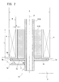
- Fig. 2 is a structural drawing showing the outline of the internal structure of the encoder unit U.
- Fig. 2 shows a state in which the encoder unit U is cut by a plane along the central axis X of the motor 1.
- a sensor (detection element) 11 and a sensor board (detection board) 7 for implementing the sensor 11 are arranged in the encoder unit U.
- the lower part (one end part) 5a of the shaft 5 penetrates the encoder unit U.
- the sensor board 7 is a circuit board with the sensor 11 implemented on its surface.
- a flange part 5b projecting toward the outer circumference of the shaft 5 is formed in the vicinity of the lower part 5a of the shaft 5.
- a disk (detection object) 14 is arranged on the lower face (opposing face) 5c of the flange part 5b.
- the disk 14 is a planar view circular or planar view annular resin film, for example.
- the outer diameter of the disk 14 is assumed to be equal to or smaller than the outer diameter of the flange part 5b so as not to protrude from the flange part 5b.
- the planar view means the view in the direction along the central axis X.
- a plurality of detection lines is formed radially. Detection light from the sensor 11 radiates the lines on the disk 14 and is reflected to be received by the sensor 11 again. Based on the number of lines detected over a constant time, the number of rotations of the rotor 3 (i.e., rotation speed) is measured.
- the stator 4 is arranged on the circumference of the rotor 3 so as to ensure a magnetic gap G with the rotor 3.
- the stator 4, the flange part 5b of the shaft 5, the sensor 11, and the sensor board 7 are arranged as shown in Fig. 2 . That is, the lower part 4a of the stator 4 is located at the upper part of the flange part 5b. A part or all of the stator 4 overlaps the flange part 5b in the planar view. In other words, the outer circumference of the stator 4 is located inside of the outer circumference of the flange part 5b or vicinity thereof. In Fig.
- stator 4 is located at a position in the vicinity a little outside the outer circumference of the flange part 5b in the planar view, most of the stator 4 is located inside the outer circumference of the flange part 5b.
- the sensor 11 opposes the lower face 5c and is arranged on opposite side the stator 4 when viewed from the flange part 5b.
- the flange part 5b is located between the sensor board 7 and stator 4. That is, in the direction along the central axis X, the sensor 11 and sensor board 7 are arranged outside the stator 4.
- the sensor board 7 overlaps the flange part 5b in the planar view.
- the end part 7a of the sensor board 7 is arranged at a position so as not to protrude from the outer circumference of the flange part 5b in the planar view.
- the motor 1 employs a reflection type sensor 11 for detecting the rotation of the rotor 3. No light-emitting element for floodlighting is provided separately from the sensor. Therefore, the stator 4 does not have to be arranged while avoiding the light-emitting element. As a result, a margin is created for the internal space of the motor 1. It is possible to reduce an outer diameter D of the stator 4 while maintaining the property of the motor. The outer diameter of the entire motor 1 can be made small. While downsizing the outer diameter of the stator 4, a size W in the radial direction of the stator 4 can be increased, enabling the number of winding wires of an armature coil to be increased. The properties of the motor are improved, and at a time, a length L of the stator 4 can also be reduced while maintaining the property of the motor. The total length of the motor 1 can be reduced.
- the flange part 5b is located between the sensor 11 and the sensor board 7, and the stator 4.
- the flange part 5b is integrally formed with the shaft 5, providing a shielding effect from electromagnetic noise since it is made of metal.
- the flange part 5b effectively prevents the electromagnetic noise from the stator 4 from affecting elements and circuits on the sensor board 7.
- the rotating electrical machine has been described as a motor (electrical motor) 1; however, the rotating electrical machine may be a generator including the rotor 3 and the stator 4 with the same configuration as the motor 1.
- the number of slots of the stator 4 is not limited.
- the motor is not limited to the outer stator (inner rotor) type explained in the embodiment.
- An inner stator (outer rotor) type motor may be applicable.
- the DD motor is not limited as long as the motor performs servo control.
- the flange part may be formed in the vicinity of one end part of the rotor, located between the stator and detection board, and may project from the rotor toward the outer circumference so as to block between the stator and detection board.
- the detection element and the detection board may be arranged so as not to protrude outside the flange part.
- a detection object that detects the rotation of the rotor by the detection element may be arranged on the face opposing the detection element of the flange part.
- the detection object may be a planar view circular shape or a planar view annular shape and arranged so as not to protrude outside the flange part.
- the detection object may be a disk on which a plurality of detection lines is formed radially.
- the detection object may be a resin film.
- the rotor may include a rotor shaft configuring a rotation shaft and a rotor core arranged on the outer circumference of the rotor shaft.
- the flange part may be formed on the rotor shaft.
- the rotor shaft may be a hollow shaft.
- the rotor shaft may be fixed at the center of the core in the planar view by shrink-fitting.
- the rotor shaft may be fixed at the center of the core in the planar view by press-fitting.
- the rotating electrical machine may be a motor or a generator.
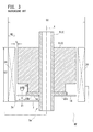
- Fig. 3 shows a structural drawing showing the outline of the internal structure of a conventional encoder unit U2.
- Fig. 3 shows a state in which the encoder unit U2 is cut in the plane along the central axis X of the motor.
- the same symbols are given to the same configuration as Fig. 2 and descriptions are abbreviated.
- a sensor (detection element) 21, a sensor board (detection board) 7 for implementing the sensor 21, and an LED (light-emitting element) 15 are arranged in an encoder unit U2.
- the lower part (one end part) of a shaft 5a enters the encoder unit U2.
- the sensor 21 is an element for detecting the rotation of the rotor 3 like the sensor 11.
- the sensor 21 is a transmission type optical sensor.
- the sensor 21 receives detection light from a LED 15 through the disk 14.
- the LED 15 is arranged on the opposite side from the sensor 21 when viewed from the disk 14. That is, the LED 15 is located at the upper part of the flange part 25b.
- the detection light from the LED 15 is adapted to transmit the disk 14 to reach the sensor 21. Therefore, the disk 14 needs to have a transparent film as a base material. A plurality of detection lines are formed on such transparent film.
- the detection position of the disk 14, that is, the transit position of the detection light has to be outside the flange part 25b. Accordingly, the disk 14 is arranged so as to partially protrude from the flange part 25b.
- the stator 24 Since the LED 15 is arranged upwards from flange part 25b, the stator 24 has to be arranged by avoiding the LED 15. That is, an outer diameter D2 of a stator 24 is larger than the outer diameter D of the stator 4. Alternatively, a size W2 in the radial direction of the stator 24 is smaller than the size W in the radial direction of the stator 4. Compared with the above motor 1 according to the embodiment, a conventional motor has a larger outer diameter or poorer motor property. In order to ensure the property of the motor, as shown in Fig. 3 , it is necessary to make a length L2 of the stator 24 longer than the length L of the stator 4 to extend to the position up to the position downward of the flange part 25b.
- the disk 14 has to be arranged while protruding from the flange part 25b. Accordingly, the flange part 25b is not located between the sensor 21 and the sensor board 7, and the stator 24.
- the flange part 25b blocks almost no electromagnetic noise from the stator 24 that affects the element and circuit on the sensor board 7.
- a metal tape (aluminum tape, copper foil tape, and the like) for preventing electromagnetic noise needs to be arranged at the position between the stator 24 and sensor board 7, for example, at the end part 7a of the sensor board 7.
Landscapes
- Engineering & Computer Science (AREA)
- Power Engineering (AREA)
- Microelectronics & Electronic Packaging (AREA)
Abstract
The object of the present invention is to provide a rotating electrical machine capable of being downsized and having a detection element 11 for detecting the rotation of a pemanent magnet rotor along with a detection board.
A motor 1 includes an almost annular stator 4, a rotor 3 arranged inside the stator ring for rotating about a central axis X, a sensor 11 for detecting the rotation of the rotor 3, and a sensor board 7 for implementing the sensor 11. The sensor 11 and the sensor board 7 are arranged outside the stator 4 in axial direction (along the central axis X). The sensor 11 is working with projecting and receiving of light while the disc reflects the emitted light.
Description
- The present invention relates to rotating electrical machine.
- Conventionally, a rotation sensor is provided in rotating electrical machines for controlling the rotation of a rotating electrical machine such as an electrical motor. The rotation sensor optically detects the rotation of the rotor. For example, a sensor board for processing signals detected by some rotation sensors is arranged in a motor (refer to Japanese Unexamined Patent Application Publication
2008-259252 - There are needs for downsizing the rotating electrical machine, particularly in the radial direction, that is, in the axial orthogonal plane of the rotating electrical machine. In addition, there also are needs for downsizing the rotating electrical machine in the length direction, that is, in the axial direction of the rotating electrical machine.
- There is another need for further reducing the influence of noise on the rotation sensor and the sensor board from the stator. By doing away with noise countermeasures such as covering the sensor board with copper foil tape, etc., the reduction of the number of components and the improvement in manufacturing efficiency can be achieved, thereby contributing to cost reduction.
- When assembling the rotating electrical machine, a detection object such as an encoder disk used for rotation detection is attached to the rotor in some cases. Consequently, a more preferable configuration of the rotating electrical machine is desired such that the attachment process is easily completed without any damage on the detection object.
- The object of the present invention is to provide a rotating electrical machine capable of being downsized and having a detection element for detecting the rotation of the rotor along with a detection board.
- The rotating electrical machine includes: an almost annular stator; a rotor arranged inside the annular ring of the stator for rotating about a rotation shaft; a detection element for detecting rotation of the rotor; and a detection board for implementing the detection element. The detection element and the detection board are arranged outside the stator in the direction along the rotation shaft. The detection element is a reflection type light projecting/receiving sensor.
- A more complete appreciation of the invention and many of the attendant advantages thereof will be readily obtained as the same becomes better understood by reference to the following detailed description when considered in connection with the accompanying drawings.
-
Fig. 1 shows an exploded perspective view of the motor related toEmbodiment 1. -
Fig. 2 shows a structural drawing showing the outline of the internal structure of the encoder unit shown inFig. 1 . -
Fig. 3 shows a structural drawing showing the outline of the internal structure of a conventional encoder unit. - Hereinafter, a motor (electrical motor) 1 as a type of a rotating electrical machine related to Embodiments is described with respect to the drawings.
Fig. 1 is an exploded perspective view of themotor 1 related to Embodiments. Themotor 1 is an inner rotor type direct-drive (DD) motor. Servo control is possible with themotor 1. In therotor 3, a permanent magnet is used as a magnetic field. Themotor 1 comprises amotor case 2, a rotor (rotator, inner rotor) 3, abearing 12, a stator (outer stator) 4, and an encoder unit U. - The
motor case 2 is a casing configuring the outer wall of themotor 1 with a throughhole 2a opening in the upper surface thereof. Therotor 3 is arranged as a field magnet inside themotor case 2. Therotor 3 is constituted such that at the center of arotor core 6, ametal shaft 5 is fixed by press-fitting, shrink-fitting, etc. In the present embodiment, theshaft 5 is, for example, a hollow shaft. Between themotor case 2 and therotor 3, thebearing 12 is arranged. Therotor 3 includes a plurality of permanent magnets seriately arranged so as to be of alternately differing poles. The plurality of permanent magnets is circumferentially arranged along the circumferential surface of therotor 3. - The
shaft 5 penetrates the center hole of thebearing 12 and the throughhole 2a of themotor case 2. The outer ring of thebearing 12 is connected to themotor case 2 and by means of the inner ring of thebearing 12 connected to theshaft 5 of therotor 3, theentire rotor 3 is made rotatable in the α direction of the arrow in the figure, revolving around the central axis (rotation shaft) X of theshaft 5 with respect to themotor case 2. - The
bearing 12 can be configured to be sandwiched between themotor case 2 and therotor 3 without connecting to themotor case 2 and/or therotor 3. Below therotor 3, abottom ring 13 covering the bottom surface of themotor case 2 is arranged. Thebearing 12 is also arranged between therotor 3 and thebottom ring 13 such that it rotatably supports therotor 3. - Moreover, in the present specifications, for convenience, the vertical direction in
Fig. 1 is defined as the vertical direction in themotor 1, using names such as the upper surface, bottom surface, etc. However, needless to say, the vertical direction is not limited to the vertical direction inFig. 1 , depending on the manner in which the motor is used. - Outside the
rotor 3, astator 4 as an armature is arranged so as to surround therotor 3. The overall cross-section of thestator 4 through the axial orthogonal plane (the plane with a central axis X in the normal direction) is circular. Thestator 4 includes a stator core (not shown) with a plurality of circumferentially arranged teeth and a plurality of armature coils (not shown) inserted into the plurality of teeth, respectively. The respective armature coils are connected to an AC power supply corresponding to each phase from among: two-phase, three-phase, or more. When each phase is energized by an electrical current of different phases, therotor 3 is adapted to rotate via electromagnetic induction. Detailed descriptions of the structure and function of the stator are abbreviated. - Inside the
motor case 2, an encoder unit U is arranged downward from thestator 4 and upward from alower cover 13. The encoder unit U detects the rotation speed of therotor 3. A controller (not shown) is connected to themotor 1. The rotation speed detected by the encoder unit U is transmitted to the controller and feedback control (servo control) based on the rotation speed is adapted to be performed. -
Fig. 2 is a structural drawing showing the outline of the internal structure of the encoder unit U.Fig. 2 shows a state in which the encoder unit U is cut by a plane along the central axis X of themotor 1. A sensor (detection element) 11 and a sensor board (detection board) 7 for implementing thesensor 11 are arranged in the encoder unit U. The lower part (one end part) 5a of theshaft 5 penetrates the encoder unit U. - The
sensor 11 is an element for detecting rotation of the shaft 5 (= rotation of the rotor 3) and a reflection type optical sensor is employed in the present embodiment. Accordingly, detection light is floodlighted from thesensor 11 to the shaft 5 (more specifically, to adisk 14 to be mentioned later), then reflected light from theshaft 5 is received again by thesensor 11. Thesensor board 7 is a circuit board with thesensor 11 implemented on its surface. - As shown in
Fig. 2 , aflange part 5b projecting toward the outer circumference of theshaft 5 is formed in the vicinity of thelower part 5a of theshaft 5. A disk (detection object) 14 is arranged on the lower face (opposing face) 5c of theflange part 5b. Thedisk 14 is a planar view circular or planar view annular resin film, for example. The outer diameter of thedisk 14 is assumed to be equal to or smaller than the outer diameter of theflange part 5b so as not to protrude from theflange part 5b. When arranging thedisk 14 on thelower face 5c, thedisk 14 is protected by theflange part 5b. This can avoid a situation in which the edge part of thedisk 14 is damaged during the assembling process of themotor 1. The planar view means the view in the direction along the central axis X. - On the
disk 14, a plurality of detection lines is formed radially. Detection light from thesensor 11 radiates the lines on thedisk 14 and is reflected to be received by thesensor 11 again. Based on the number of lines detected over a constant time, the number of rotations of the rotor 3 (i.e., rotation speed) is measured. - The
stator 4 is arranged on the circumference of therotor 3 so as to ensure a magnetic gap G with therotor 3. With themotor 1 according to the present embodiment, thestator 4, theflange part 5b of theshaft 5, thesensor 11, and thesensor board 7 are arranged as shown inFig. 2 . That is, thelower part 4a of thestator 4 is located at the upper part of theflange part 5b. A part or all of thestator 4 overlaps theflange part 5b in the planar view. In other words, the outer circumference of thestator 4 is located inside of the outer circumference of theflange part 5b or vicinity thereof. InFig. 2 , although the outer circumference of thestator 4 is located at a position in the vicinity a little outside the outer circumference of theflange part 5b in the planar view, most of thestator 4 is located inside the outer circumference of theflange part 5b. - The
sensor 11 opposes thelower face 5c and is arranged on opposite side thestator 4 when viewed from theflange part 5b. Theflange part 5b is located between thesensor board 7 andstator 4. That is, in the direction along the central axis X, thesensor 11 andsensor board 7 are arranged outside thestator 4. Thesensor board 7 overlaps theflange part 5b in the planar view. Theend part 7a of thesensor board 7 is arranged at a position so as not to protrude from the outer circumference of theflange part 5b in the planar view. - The
motor 1 employs areflection type sensor 11 for detecting the rotation of therotor 3. No light-emitting element for floodlighting is provided separately from the sensor. Therefore, thestator 4 does not have to be arranged while avoiding the light-emitting element. As a result, a margin is created for the internal space of themotor 1. It is possible to reduce an outer diameter D of thestator 4 while maintaining the property of the motor. The outer diameter of theentire motor 1 can be made small. While downsizing the outer diameter of thestator 4, a size W in the radial direction of thestator 4 can be increased, enabling the number of winding wires of an armature coil to be increased. The properties of the motor are improved, and at a time, a length L of thestator 4 can also be reduced while maintaining the property of the motor. The total length of themotor 1 can be reduced. - The
flange part 5b is located between thesensor 11 and thesensor board 7, and thestator 4. Theflange part 5b is integrally formed with theshaft 5, providing a shielding effect from electromagnetic noise since it is made of metal. Theflange part 5b effectively prevents the electromagnetic noise from thestator 4 from affecting elements and circuits on thesensor board 7. - As above, the embodiment of the present invention was described; however, the present invention is not limited to this and various arrangements and modifications are possible within the range of the summary thereof.
- In the abovementioned embodiments, the rotating electrical machine has been described as a motor (electrical motor) 1; however, the rotating electrical machine may be a generator including the
rotor 3 and thestator 4 with the same configuration as themotor 1. In addition, the number of slots of thestator 4 is not limited. The motor is not limited to the outer stator (inner rotor) type explained in the embodiment. An inner stator (outer rotor) type motor may be applicable. In addition, the DD motor is not limited as long as the motor performs servo control. - The flange part may be formed in the vicinity of one end part of the rotor, located between the stator and detection board, and may project from the rotor toward the outer circumference so as to block between the stator and detection board. When viewed along the rotation shaft, the detection element and the detection board may be arranged so as not to protrude outside the flange part.
- A detection object that detects the rotation of the rotor by the detection element may be arranged on the face opposing the detection element of the flange part.
- The detection object may be a planar view circular shape or a planar view annular shape and arranged so as not to protrude outside the flange part. The detection object may be a disk on which a plurality of detection lines is formed radially. Alternatively, the detection object may be a resin film.
- The rotor may include a rotor shaft configuring a rotation shaft and a rotor core arranged on the outer circumference of the rotor shaft. The flange part may be formed on the rotor shaft.
- The rotor shaft may be a hollow shaft.
- The rotor shaft may be fixed at the center of the core in the planar view by shrink-fitting.
- The rotor shaft may be fixed at the center of the core in the planar view by press-fitting.
- The rotating electrical machine may be a motor or a generator.
- Obviously, numerous modifications and variations of the present invention are possible in light of the above teachings. It is therefore to be understood that within the scope of the appended claims, the invention may be practiced otherwise than as specifically described herein.
- Downsizing a rotating electrical machine with a detection element for detecting rotation of the rotor and a detection board is achieved.
-
Fig. 3 shows a structural drawing showing the outline of the internal structure of a conventional encoder unit U2.Fig. 3 shows a state in which the encoder unit U2 is cut in the plane along the central axis X of the motor. In addition, inFig. 3 , the same symbols are given to the same configuration asFig. 2 and descriptions are abbreviated. - A sensor (detection element) 21, a sensor board (detection board) 7 for implementing the
sensor 21, and an LED (light-emitting element) 15 are arranged in an encoder unit U2. In addition, the lower part (one end part) of ashaft 5a enters the encoder unit U2. - The
sensor 21 is an element for detecting the rotation of therotor 3 like thesensor 11. Thesensor 21 is a transmission type optical sensor. Thesensor 21 receives detection light from aLED 15 through thedisk 14. TheLED 15 is arranged on the opposite side from thesensor 21 when viewed from thedisk 14. That is, theLED 15 is located at the upper part of theflange part 25b. - The detection light from the
LED 15 is adapted to transmit thedisk 14 to reach thesensor 21. Therefore, thedisk 14 needs to have a transparent film as a base material. A plurality of detection lines are formed on such transparent film. The detection position of thedisk 14, that is, the transit position of the detection light has to be outside theflange part 25b. Accordingly, thedisk 14 is arranged so as to partially protrude from theflange part 25b. - Since the
LED 15 is arranged upwards fromflange part 25b, thestator 24 has to be arranged by avoiding theLED 15. That is, an outer diameter D2 of astator 24 is larger than the outer diameter D of thestator 4. Alternatively, a size W2 in the radial direction of thestator 24 is smaller than the size W in the radial direction of thestator 4. Compared with theabove motor 1 according to the embodiment, a conventional motor has a larger outer diameter or poorer motor property. In order to ensure the property of the motor, as shown inFig. 3 , it is necessary to make a length L2 of thestator 24 longer than the length L of thestator 4 to extend to the position up to the position downward of theflange part 25b. - The
disk 14 has to be arranged while protruding from theflange part 25b. Accordingly, theflange part 25b is not located between thesensor 21 and thesensor board 7, and thestator 24. Theflange part 25b blocks almost no electromagnetic noise from thestator 24 that affects the element and circuit on thesensor board 7. In order to prevent the electromagnetic noise from thestator 24 from affecting the element and circuit on thesensor board 7, a metal tape (aluminum tape, copper foil tape, and the like) for preventing electromagnetic noise needs to be arranged at the position between thestator 24 andsensor board 7, for example, at theend part 7a of thesensor board 7.
Claims (13)
- A rotating electrical machine, comprising:a stator of an almost annular shape,a rotor arranged inside an annular ring of the stator for rotating about a rotation shaft,a detection element for detecting the rotation of the rotor, anda detection board for implementing the detection element, whereinthe detection element and the detection board are arranged outside the stator in the direction along the rotation shaft, andthe detection element is a reflection type light projecting/receiving sensor.
- The rotating electrical machine according to claim 1, wherein
a flange part is formed in the vicinity of one end part of the rotor, and
the flange part is located between the stator and the detection board and projects from the rotor towards the outer circumference so as to block between the stator and the detection board. - The rotating electrical machine according to claim 2, wherein,
when viewed from the direction indicated by the arrow along the rotation shaft, the detection element and the detection board are arranged so as not to protrude outside the flange part. - The rotating electrical machine according to claim 2 or 3, wherein
a detection object detecting the rotation of the rotor by the detection element is arranged on the face opposing the detection element of the flange part. - The rotating electrical machine according to claim 4, wherein
the detection object is a planar view circular shape or a planar view annular shape and arranged so as not to protrude outside the flange part. - The rotating electrical machine according to claim 4 or 5, wherein
the detection object is a disk on which a plurality of detection lines is formed radially. - The rotating electrical machine according to any one of claims 4 to 6, wherein
the detection object is a resin film. - The rotating electrical machine according to any one of claims 2 to 7, wherein
the rotor includes a rotor shaft configuring the rotation axis and a rotor core arranged on
the outer circumference of the rotor shaft, and
the flange part is formed on the rotor shaft. - The rotating electrical machine according to claim 8, wherein
the rotor shaft is a hollow shaft. - The rotating electrical machine according to claim 8 or 9, wherein
the rotor shaft is fixed at the center of the rotor core in the planar view by shrink-fitting. - The rotating electrical machine according to claim 8 or 9, wherein
the rotor shaft is fixed at the center of the rotor core in the planar view by press-fitting. - The rotating electrical machine according to any one of claims 1 to 11, wherein
the rotating electrical machine is a motor. - The rotating electrical machine according to any one from among claims 1 to 11, wherein
the rotating electrical machine is a generator.
Applications Claiming Priority (1)
| Application Number | Priority Date | Filing Date | Title |
|---|---|---|---|
| JP2012210975A JP5747887B2 (en) | 2012-09-25 | 2012-09-25 | Rotating electric machine |
Publications (1)
| Publication Number | Publication Date |
|---|---|
| EP2712069A2 true EP2712069A2 (en) | 2014-03-26 |
Family
ID=47739115
Family Applications (1)
| Application Number | Title | Priority Date | Filing Date |
|---|---|---|---|
| EP13155034.5A Withdrawn EP2712069A2 (en) | 2012-09-25 | 2013-02-13 | Rotating electrical machine |
Country Status (5)
| Country | Link |
|---|---|
| US (1) | US8823225B2 (en) |
| EP (1) | EP2712069A2 (en) |
| JP (1) | JP5747887B2 (en) |
| KR (2) | KR20140040608A (en) |
| CN (1) | CN103683678A (en) |
Cited By (1)
| Publication number | Priority date | Publication date | Assignee | Title |
|---|---|---|---|---|
| WO2016207700A1 (en) * | 2015-06-26 | 2016-12-29 | Kotze, Gavin, Salomon | An electric rotary machine having axially-spaced groups of magnet structures |
Families Citing this family (9)
| Publication number | Priority date | Publication date | Assignee | Title |
|---|---|---|---|---|
| KR102380923B1 (en) * | 2014-12-23 | 2022-04-01 | 엘지이노텍 주식회사 | Shaft assembly and Motor having the same |
| DE102016002387B4 (en) | 2015-04-02 | 2022-08-04 | Sew-Eurodrive Gmbh & Co Kg | sensor arrangement |
| JP6402693B2 (en) | 2015-08-24 | 2018-10-10 | マツダ株式会社 | Engine exhaust system |
| DE102015216233A1 (en) * | 2015-08-25 | 2017-03-02 | Volkswagen Aktiengesellschaft | Rotor position system with encoder contour integrated in a rotor shaft |
| DE102017106479A1 (en) | 2017-03-27 | 2018-09-27 | Fritz Kübler GmbH | Shielding system for magnetic encoder sensor system |
| JP6770033B2 (en) * | 2018-09-06 | 2020-10-14 | ファナック株式会社 | Encoder rotating member mounting structure and encoder rotating member mounting method |
| CN109888978B (en) * | 2019-03-15 | 2020-09-25 | 浙江绿源电动车有限公司 | Oil-cooled motor |
| DE102021104635A1 (en) * | 2021-02-26 | 2022-09-01 | Bayerische Motoren Werke Aktiengesellschaft | Target carrier for a non-contact rotor position sensor, rotor, electric drive unit and motor vehicle |
| KR20220126501A (en) * | 2021-03-09 | 2022-09-16 | 엘지이노텍 주식회사 | motor |
Citations (1)
| Publication number | Priority date | Publication date | Assignee | Title |
|---|---|---|---|---|
| JP2008259252A (en) | 2007-03-30 | 2008-10-23 | Yaskawa Electric Corp | Stator and its gap winding motor |
Family Cites Families (17)
| Publication number | Priority date | Publication date | Assignee | Title |
|---|---|---|---|---|
| JPS5963670U (en) * | 1982-10-19 | 1984-04-26 | オリンパス光学工業株式会社 | Motor with servo |
| JPS60162966U (en) * | 1984-04-09 | 1985-10-29 | 株式会社東芝 | rotating electric machine |
| JPH0265079U (en) * | 1988-11-04 | 1990-05-16 | ||
| JPH0777520B2 (en) * | 1990-01-29 | 1995-08-16 | 日本建鐵株式会社 | Motor speed detection method |
| JP2573859Y2 (en) * | 1991-11-21 | 1998-06-04 | 株式会社ハーモニック・ドライブ・システムズ | Home position return mechanism for electromagnetic finite rotary motor |
| JP2862053B2 (en) * | 1993-04-02 | 1999-02-24 | 三菱電機株式会社 | Motor with drive control device |
| JPH07239244A (en) * | 1994-02-28 | 1995-09-12 | Kokusai Keisokki Kk | Rotary shaft with code disc and method of forming rotary shaft with code disc |
| GB2311423B (en) * | 1996-03-19 | 2000-05-10 | Switched Reluctance Drives Ltd | An electrical machine drive system including an optical position transducer circuit |
| JPH09308171A (en) * | 1996-05-13 | 1997-11-28 | Sankyo Seiki Mfg Co Ltd | Motor with magnetic type encoder |
| JPH1047994A (en) * | 1996-08-07 | 1998-02-20 | Matsushita Electric Ind Co Ltd | Rotational position detector |
| US6522130B1 (en) * | 1998-07-20 | 2003-02-18 | Uqm Technologies, Inc. | Accurate rotor position sensor and method using magnet and sensors mounted adjacent to the magnet and motor |
| JP3743348B2 (en) * | 2001-11-12 | 2006-02-08 | 三菱電機株式会社 | Synchronous induction motor, method for manufacturing synchronous induction motor, compressor |
| US6909212B2 (en) * | 2003-02-27 | 2005-06-21 | Asmo Co., Ltd. | Motor having rotation sensor and manufacturing method thereof |
| JP5076676B2 (en) * | 2007-06-26 | 2012-11-21 | 株式会社ニコン | Reflective encoder and motor |
| JP2011095180A (en) * | 2009-10-30 | 2011-05-12 | Iai:Kk | Encoder and servomotor |
| JP5287787B2 (en) * | 2010-04-16 | 2013-09-11 | 株式会社デンソー | Electric device |
| CN102148599B (en) * | 2010-12-22 | 2012-11-07 | 大连理工大学 | Angle position detector of switched reluctance motor and detection method |
-
2012
- 2012-09-25 JP JP2012210975A patent/JP5747887B2/en not_active Expired - Fee Related
-
2013
- 2013-02-13 EP EP13155034.5A patent/EP2712069A2/en not_active Withdrawn
- 2013-03-11 US US13/792,200 patent/US8823225B2/en not_active Expired - Fee Related
- 2013-03-18 KR KR1020130028592A patent/KR20140040608A/en not_active Ceased
- 2013-03-19 CN CN201310086914.XA patent/CN103683678A/en active Pending
-
2015
- 2015-03-05 KR KR1020150030693A patent/KR101555804B1/en not_active Expired - Fee Related
Patent Citations (1)
| Publication number | Priority date | Publication date | Assignee | Title |
|---|---|---|---|---|
| JP2008259252A (en) | 2007-03-30 | 2008-10-23 | Yaskawa Electric Corp | Stator and its gap winding motor |
Cited By (1)
| Publication number | Priority date | Publication date | Assignee | Title |
|---|---|---|---|---|
| WO2016207700A1 (en) * | 2015-06-26 | 2016-12-29 | Kotze, Gavin, Salomon | An electric rotary machine having axially-spaced groups of magnet structures |
Also Published As
| Publication number | Publication date |
|---|---|
| US8823225B2 (en) | 2014-09-02 |
| US20140084757A1 (en) | 2014-03-27 |
| KR20150035911A (en) | 2015-04-07 |
| JP2014068444A (en) | 2014-04-17 |
| KR20140040608A (en) | 2014-04-03 |
| CN103683678A (en) | 2014-03-26 |
| KR101555804B1 (en) | 2015-09-24 |
| JP5747887B2 (en) | 2015-07-15 |
Similar Documents
| Publication | Publication Date | Title |
|---|---|---|
| US8823225B2 (en) | Rotating electrical machine | |
| CN108155762B (en) | Resolver and motor | |
| KR20070120858A (en) | Axial Airflow Motor | |
| JP6766535B2 (en) | Stator unit, motor, and fan motor | |
| JP7293680B2 (en) | motor and blower | |
| CN109104007A (en) | Brushless motor and its stator | |
| JP4801713B2 (en) | Brushless DC motor | |
| EP3719977A1 (en) | Motor and electric device including motor | |
| US8823240B2 (en) | Stator and rotating electrical machine | |
| JP4924158B2 (en) | Stator and its gap winding motor | |
| JP4695010B2 (en) | Brushless motor with built-in circuit board | |
| JP6559370B1 (en) | Encoder and servo motor | |
| JP2021057932A (en) | Motor and blower | |
| JP2014003799A (en) | Brushless motor | |
| CN211701704U (en) | Motor with a stator having a stator core | |
| CN111052563B (en) | Electric machine system | |
| US20160172914A1 (en) | Rotor, motor, pump and cleaning apparatus | |
| JPH1118361A (en) | Controller integrated motor | |
| JP6988357B2 (en) | Rotating machine and manufacturing method of rotating machine | |
| JP5290608B2 (en) | Axial gap motor | |
| US11005333B2 (en) | Electric motor having a stator with a radially outside rotor with the rotor having a fan mounting portion comprising a noncontact region and a contract region configured to contact a mouting surface of a fan | |
| JP2012110187A (en) | Brushless motor and rotor frame | |
| JP5277605B2 (en) | Brushless motor | |
| US20260100623A1 (en) | Brushless motor | |
| JP5360099B2 (en) | Rotating electric machine |
Legal Events
| Date | Code | Title | Description |
|---|---|---|---|
| PUAI | Public reference made under article 153(3) epc to a published international application that has entered the european phase |
Free format text: ORIGINAL CODE: 0009012 |
|
| AK | Designated contracting states |
Kind code of ref document: A2 Designated state(s): AL AT BE BG CH CY CZ DE DK EE ES FI FR GB GR HR HU IE IS IT LI LT LU LV MC MK MT NL NO PL PT RO RS SE SI SK SM TR |
|
| AX | Request for extension of the european patent |
Extension state: BA ME |
|
| STAA | Information on the status of an ep patent application or granted ep patent |
Free format text: STATUS: THE APPLICATION IS DEEMED TO BE WITHDRAWN |
|
| 18D | Application deemed to be withdrawn |
Effective date: 20170901 |