EP2712029A1 - A contact carrier unit for an electrical connection socket or plug - Google Patents
A contact carrier unit for an electrical connection socket or plug Download PDFInfo
- Publication number
- EP2712029A1 EP2712029A1 EP13184873.1A EP13184873A EP2712029A1 EP 2712029 A1 EP2712029 A1 EP 2712029A1 EP 13184873 A EP13184873 A EP 13184873A EP 2712029 A1 EP2712029 A1 EP 2712029A1
- Authority
- EP
- European Patent Office
- Prior art keywords
- lever
- electrical connection
- conductor
- seat
- unit according
- Prior art date
- Legal status (The legal status is an assumption and is not a legal conclusion. Google has not performed a legal analysis and makes no representation as to the accuracy of the status listed.)
- Granted
Links
Images

Classifications
-
- H—ELECTRICITY
- H01—ELECTRIC ELEMENTS
- H01R—ELECTRICALLY-CONDUCTIVE CONNECTIONS; STRUCTURAL ASSOCIATIONS OF A PLURALITY OF MUTUALLY-INSULATED ELECTRICAL CONNECTING ELEMENTS; COUPLING DEVICES; CURRENT COLLECTORS
- H01R4/00—Electrically-conductive connections between two or more conductive members in direct contact, i.e. touching one another; Means for effecting or maintaining such contact; Electrically-conductive connections having two or more spaced connecting locations for conductors and using contact members penetrating insulation
- H01R4/24—Connections using contact members penetrating or cutting insulation or cable strands
- H01R4/2416—Connections using contact members penetrating or cutting insulation or cable strands the contact members having insulation-cutting edges, e.g. of tuning fork type
- H01R4/242—Connections using contact members penetrating or cutting insulation or cable strands the contact members having insulation-cutting edges, e.g. of tuning fork type the contact members being plates having a single slot
- H01R4/2425—Flat plates, e.g. multi-layered flat plates
- H01R4/2429—Flat plates, e.g. multi-layered flat plates mounted in an insulating base
- H01R4/2433—Flat plates, e.g. multi-layered flat plates mounted in an insulating base one part of the base being movable to push the cable into the slot
-
- H—ELECTRICITY
- H01—ELECTRIC ELEMENTS
- H01R—ELECTRICALLY-CONDUCTIVE CONNECTIONS; STRUCTURAL ASSOCIATIONS OF A PLURALITY OF MUTUALLY-INSULATED ELECTRICAL CONNECTING ELEMENTS; COUPLING DEVICES; CURRENT COLLECTORS
- H01R4/00—Electrically-conductive connections between two or more conductive members in direct contact, i.e. touching one another; Means for effecting or maintaining such contact; Electrically-conductive connections having two or more spaced connecting locations for conductors and using contact members penetrating insulation
- H01R4/24—Connections using contact members penetrating or cutting insulation or cable strands
- H01R4/2416—Connections using contact members penetrating or cutting insulation or cable strands the contact members having insulation-cutting edges, e.g. of tuning fork type
Definitions
- the present invention relates to a contact carrier unit for an electrical connection socket or plug having the features defined in the preamble of Claim 1.
- the invention is applicable both to electrical connection sockets or plugs of the fixed type and to sockets or plugs of the movable or "in-line" type normally used in industry.
- a socket or plug of the aforesaid type is known from patent publication WO 2004/105186 A1 .
- Sockets or plugs are connected to the ends of an electrical cable and they generally each comprise a containment casing forming within itself a generally cylindrical housing seat for a contact carrier unit (also called the "body") which carries a plurality of electrical contacts formed by pairs of blades lying in a plane perpendicular to the direction x along which the socket or plug is coupled to a matching plug or socket. Each pair of blades can receive one of the conductors of an electrical cable which is to be connected electrically to the unit.
- a lever for guiding and locking a conductor of the cable is mounted on the body of the contact carrier, near each pair of blades.
- Each lever generally has an engagement means (such as an annular formation) to assist in the correct positioning of the conductor, and is hinged to the body of the contact carrier about an axis of rotation perpendicular to the direction of coupling.
- the lever can be rotated in an axial plane parallel to the direction of coupling so as to reach an open or unlocked position, for example during an operation of connection/disconnection or replacement of the conductors, in which the conductor retained by the lever is removed and is disengaged from the pair of blades.
- the lever is rotated into a closed position, thus forcing the conductor retained by the lever to slide between the pair of blades and to remain locked in a position of insertion between the blades. In the closed position, part of the lever projects beyond the body, enabling the lever to be unlocked conveniently by a manual operation.
- the object of the present invention is to provide a contact carrier unit which enables conductors of different thicknesses to be connected effectively.
- each lever can retain, in at least two distinct positions, conductors of different thicknesses which can be positioned selectively in one of two different retention holes formed in the lever in positions aligned in the same axial plane parallel to the direction of coupling and uncoupling of the socket or plug.
- a blade-like electrical contact is provided, having a slit orientated in the axial plane in which the two retention holes of the lever lie.
- the two widenings form electrical connection seats for respective conductors.
- the conductor is inserted into the hole in the lever which is axially aligned with the narrower of the widenings or electrical connection seats when the lever is rotated to an axially orientated closed position in which it forces the conductor to be inserted into the slit.
- a thicker conductor is to be connected, it is inserted into the retaining hole which will be axially aligned, when the lever is in the closed position, with the wider electrical connection seat.
- the number 10 indicates the whole of a contact carrier unit for an electrical connection socket or plug that can be coupled to a corresponding plug or socket in a given direction of coupling, parallel to or coinciding with an axis indicated by x.
- the unit 10 is designed to be incorporated into a sleeve-like housing (not shown) of an electrical socket or plug of the movable or "in-line" type.
- the reference to this possible field of application is not to be interpreted as in any way limiting the scope of the patent, which is also applicable to sockets or plugs of the fixed type.
- the contact carrier unit comprises a body 11 having an overall cylindrical shape which has a plurality of peripheral recesses 13, there being three of these recesses in the present example.
- each recess there is mounted a respective electrical contact 14 (illustrated separately) having a pair of facing blades 15, 16.
- Each pair of blades has a radially extending slit 17, is open at a radially outer end 22, and is delimited by two facing contact edges 18, 19.
- the contact edges are suitably shaped to form two electrical connection seats 20, 21, located in two respective radially distinct positions, which can selectively retain an electrical conductor C1 or C2 of an electrical cable which is to be connected electrically to the socket or plug.
- the first electrical connection seat 20, which is the radially inner seat or the seat closer to the central axis x of the unit, is formed by a widening which is preferably located at the radially inner end of the slit 17, and serves to retain an electrical conductor C1 having a given maximum cross section, for example a maximum cross section of 6 mm 2 .
- the second electrical connection seat 21, which is the radially outer seat or the seat farther from the axis x, is formed by a widening located in an intermediate position between the first seat 20 and the radially outer opening or end 22 of the slit 17.
- the second seat 21 is wider than the first seat 20, and is conveniently designed to retain an electrical conductor C2 ( Figures 10 - 13 ) having a cross section greater than the maximum cross section of the conductor that can be received in the first seat 20.
- the second seat 21 is designed to receive a conductor with a cross section of 10 mm 2 .
- the contact edges 18, 19 have cutting portions 23 adapted to cut the sheath of the conductor.
- each lever 24 for guiding and locking a respective conductor C1 or C2.
- Each lever 24 has two retaining elements, namely a first and a second retaining element 25, 26, located in positions at different radial distances from the central axis x, for selectively retaining the conductor (C1 or C2) to be electrically connected to a pair of blades.
- the first retaining element 25 comprises an annular formation forming a first through hole 25a through which the end part of a relatively thin conductor C1 can be passed so as to be placed in the first, narrower, electrical connection seat 20 of the slit 17.
- the annular formation projects from a face 24a of the lever facing the central axis x.
- the second retaining element 26 is preferably formed by a second through hole 26a made through the body of the lever. This second hole or passage 26a has a cross section greater than the transverse dimension of the first hole 25a, in order to retain a thicker conductor C2, which is to be placed in the wider second electrical connection seat 21 of the slit 17.
- Each lever 24 is hinged on the body 11 of the contact so as to be rotatable in a plane defined herein as the "axial" plane, between a disengaged position (indicated by 24', as shown by the levers located on the left-hand side of Figures 1 , 8 and 10 ) and a closed position of the electrical contact in which the lever occupies the respective recess 13 and is orientated in a substantially axial direction.
- the levers are included within the circular profile of the contact carrier unit, which can thus be inserted into the outer containment casing or sleeve (not shown).
- each lever 24 The two retaining means 25, 26 formed by each lever 24 are aligned in the same axial plane as the slit 17 formed by the contact 14 which is housed in the recess 13 where the lever is mounted.
- Each lever may be hinged to the body 11 by methods which may, for example, be similar or identical to that illustrated in WO 2004/105186 A1 , which is incorporated herein by reference. More specifically, each of the levers may have, for example, a pair of opposed pins 28 ( Figure 6 ), orientated in a tangential direction, which engage in corresponding hinge seats (not shown) formed in the body 11 of the contact carrier.
- a lever 24 In order to connect a conductor C1 or C2 electrically to the socket or plug, a lever 24 must first be placed in the open, or outwardly inclined, position.
- the conductor is threaded either into the first hole 25a or into the second hole 26a of a lever, in order to connect it electrically to the first 20 or the second 21 seat of the slit 17 respectively.
- the conductor has a cross section of not more than 6 mm 2 , it is threaded into the first hole 25a ( Figure 1 ); otherwise, it is threaded into the second hole 26a ( Figure 10 ).
- the lever 24 there are conveniently formed two stop surfaces 29, 30, against which the end of the conductor comes to bear when it is fully inserted through the first hole 25a or the second hole 26a respectively.
- Both the first and the second hole 25a, 26a are spaced apart from the base of the lever where the pins 28 are formed, so as to leave an exposed portion C1a, C2a of the cable facing the contact 14.
- a conductor is then threaded into the first hole 25a or into the second hole 26a of the lever, the cable being pushed until it meets the respective stop surface 29 or 30.
- the lever 24 is pushed manually from the open, or outwardly rotated, position 24', causing it to rotate in an axial plane so as to penetrate into the recess 13. This forces the conductor C1 or C2 retained in the hole 25a or 26a to be inserted between the edges 18, 19 of the blades 15, 16, which cut the insulating sheath of the conductor and thus make the electrical contact. In this way the lever 24 reaches a closed or locked position, in which it is orientated axially.
- Resilient locking catches 31 ( Figure 8 ) are provided, in pairs in this example, in each recess 13 of the body 11 of the contact carrier, to lock the lever 24 in the closed position by a snap-fitting action.
- the locking catches 31 engage with corresponding recesses or attachment formations 32 formed on the lever 24 ( Figure 9 ).
- an engagement means for a tool such as a recess 33 for the tip of a screwdriver, can be provided for unlocking the lever from the closed contact position.
- the recess or other engagement means for a tool is formed in the lever in a position such that it does not cause any increase in the thickness or overall radial dimension of the lever.
- the levers are all orientated parallel to the longitudinal axis of the socket or plug so that the contact carrier unit can be inserted into a housing sleeve (not shown) and locked therein.
- the recess 33 is formed adjacent to the second hole 26a, in an end portion 34 of the lever projecting in a substantially tangential direction. This enables the radial dimensions of the lever to be kept within a limited circular profile defined by the housing sleeve.
- the second, wider hole 26a can be provisionally blocked by a removable closure element 35, such as a small plate formed in one piece with the lever 24.
- the closure element 35 which can be removed, with a screwdriver 36 for example, in order to free the hole 26a, serves to prevent the erroneous insertion of a small-sized conductor into the hole 26a, since the electrical connection of a thin conductor in the wider seat 21 would not be secure.
- the electrical contact 14 which includes the slit 17 is substantially S-shaped, and has:
- the electrical contact is made in a single piece from copper sheet which is cut and bent in various ways to form the aforesaid shape. Because of its S-shaped configuration as described, the electrical contact has at least three distinct bending points which allow the contact to be resiliently deflected at a plurality of points when the conductors are forcibly inserted into the slit during the connection operations. The distribution of the deflection over a plurality of points prevents the concentration of forces, and therefore the contact is not subject to significant permanent plastic deformation and is less inclined to break or become detached after repeated connection operations.
- the S-shape of the electrical contact can also be used with conventional contact blades, which have a slit with only one seat for housing an electrical conductor.
- the invention is not limited to the embodiments described and illustrated herein, which are to be considered as examples of embodiment of the unit; in fact, the invention can be modified in respect of the forms and arrangements of parts and constructional details, and in respect of its operation.
- the conductor retaining means could be formed by holes or housings having shapes and/or dimensions other than those illustrated herein.
- the retaining seat of the contact which serves to retain thicker conductors could be formed towards the base of the slit 17, while the seat intended to house thinner conductors could be placed in an intermediate position between the base of the slit and its opening.
Landscapes
- Details Of Connecting Devices For Male And Female Coupling (AREA)
- Coupling Device And Connection With Printed Circuit (AREA)
- Connector Housings Or Holding Contact Members (AREA)
Abstract
Description
- The present invention relates to a contact carrier unit for an electrical connection socket or plug having the features defined in the preamble of Claim 1. The invention is applicable both to electrical connection sockets or plugs of the fixed type and to sockets or plugs of the movable or "in-line" type normally used in industry. A socket or plug of the aforesaid type is known from patent publication
WO 2004/105186 A1 . - Sockets or plugs are connected to the ends of an electrical cable and they generally each comprise a containment casing forming within itself a generally cylindrical housing seat for a contact carrier unit (also called the "body") which carries a plurality of electrical contacts formed by pairs of blades lying in a plane perpendicular to the direction x along which the socket or plug is coupled to a matching plug or socket. Each pair of blades can receive one of the conductors of an electrical cable which is to be connected electrically to the unit. A lever for guiding and locking a conductor of the cable is mounted on the body of the contact carrier, near each pair of blades. Each lever generally has an engagement means (such as an annular formation) to assist in the correct positioning of the conductor, and is hinged to the body of the contact carrier about an axis of rotation perpendicular to the direction of coupling. The lever can be rotated in an axial plane parallel to the direction of coupling so as to reach an open or unlocked position, for example during an operation of connection/disconnection or replacement of the conductors, in which the conductor retained by the lever is removed and is disengaged from the pair of blades. To make an electrical contact between the conductor and the pair of blades, the lever is rotated into a closed position, thus forcing the conductor retained by the lever to slide between the pair of blades and to remain locked in a position of insertion between the blades. In the closed position, part of the lever projects beyond the body, enabling the lever to be unlocked conveniently by a manual operation.
- The object of the present invention is to provide a contact carrier unit which enables conductors of different thicknesses to be connected effectively. In particular, it is desirable to provide an assured electrical connection for conductors having cross sections in the range from 2.5 mm2 to 10 mm2.
- These and other objects and advantages, which will be made clearer below, are achieved according to the invention with a contact carrier unit having the features stated in the attached claims.
- Briefly, each lever can retain, in at least two distinct positions, conductors of different thicknesses which can be positioned selectively in one of two different retention holes formed in the lever in positions aligned in the same axial plane parallel to the direction of coupling and uncoupling of the socket or plug. For each lever, a blade-like electrical contact is provided, having a slit orientated in the axial plane in which the two retention holes of the lever lie. Along the slit there are formed two widenings, one wider and one narrower, located in positions at different distances from the central axis of the unit. The two widenings form electrical connection seats for respective conductors. If a conductor having a thickness or cross section not exceeding a certain value is to be connected, the conductor is inserted into the hole in the lever which is axially aligned with the narrower of the widenings or electrical connection seats when the lever is rotated to an axially orientated closed position in which it forces the conductor to be inserted into the slit. On the other hand, if a thicker conductor is to be connected, it is inserted into the retaining hole which will be axially aligned, when the lever is in the closed position, with the wider electrical connection seat.
- The structural and functional features of some preferred, but not limiting, embodiments of a contact carrier unit according to the invention will now be described, with reference to the attached drawings, in which:
-
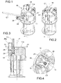
Figures 1 and 2 are perspective views of a contact carrier unit in two different positions for connecting a thin conductor; -
Figure 3 is an axial section through the unit ofFigure 2 ; -
Figure 4 is a partial sectional view taken along the line IV-IV ofFigure 3 ; -
Figure 5 is a perspective view of an electrical contact of the unit ofFigure 1 ; -
Figures 6 and 7 are a sectional view and a top view of a lever forming part of the unit ofFigure 1 ; -
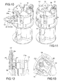
Figures 8 ,10 and 11 are perspective views of the contact carrier unit in two different positions for connecting a thicker conductor; -
Figure 9 shows a detail ofFigure 10 ; -
Figure 12 is a partial view in axial section of the unit ofFigure 11 ; and -
Figure 13 is a partial sectional view taken along the line XIII-XIII inFigure 12 . - With reference to the drawings, the
number 10 indicates the whole of a contact carrier unit for an electrical connection socket or plug that can be coupled to a corresponding plug or socket in a given direction of coupling, parallel to or coinciding with an axis indicated by x. In the present example, theunit 10 is designed to be incorporated into a sleeve-like housing (not shown) of an electrical socket or plug of the movable or "in-line" type. The reference to this possible field of application is not to be interpreted as in any way limiting the scope of the patent, which is also applicable to sockets or plugs of the fixed type. - The contact carrier unit comprises a
body 11 having an overall cylindrical shape which has a plurality ofperipheral recesses 13, there being three of these recesses in the present example. Throughout the present description and the following claims, any terms and expressions indicating positions and orientations such as "axial", "longitudinal", "transverse" and "radial" are to be interpreted as relating to the central geometrical axis x of the unit. - In each recess there is mounted a respective electrical contact 14 (illustrated separately) having a pair of facing
blades slit 17, is open at a radiallyouter end 22, and is delimited by two facingcontact edges electrical connection seats - The first
electrical connection seat 20, which is the radially inner seat or the seat closer to the central axis x of the unit, is formed by a widening which is preferably located at the radially inner end of theslit 17, and serves to retain an electrical conductor C1 having a given maximum cross section, for example a maximum cross section of 6 mm2. - The second
electrical connection seat 21, which is the radially outer seat or the seat farther from the axis x, is formed by a widening located in an intermediate position between thefirst seat 20 and the radially outer opening orend 22 of theslit 17. Thesecond seat 21 is wider than thefirst seat 20, and is conveniently designed to retain an electrical conductor C2 (Figures 10 - 13 ) having a cross section greater than the maximum cross section of the conductor that can be received in thefirst seat 20. For example, thesecond seat 21 is designed to receive a conductor with a cross section of 10 mm2. - In the illustrated embodiment, the
contact edges portions 23 adapted to cut the sheath of the conductor. - In each
recess 13 there is mounted arespective lever 24 for guiding and locking a respective conductor C1 or C2. Eachlever 24 has two retaining elements, namely a first and asecond retaining element 25, 26, located in positions at different radial distances from the central axis x, for selectively retaining the conductor (C1 or C2) to be electrically connected to a pair of blades. - In one embodiment, the
first retaining element 25 comprises an annular formation forming a first throughhole 25a through which the end part of a relatively thin conductor C1 can be passed so as to be placed in the first, narrower,electrical connection seat 20 of theslit 17. The annular formation projects from aface 24a of the lever facing the central axis x. The second retaining element 26 is preferably formed by a second throughhole 26a made through the body of the lever. This second hole orpassage 26a has a cross section greater than the transverse dimension of thefirst hole 25a, in order to retain a thicker conductor C2, which is to be placed in the wider secondelectrical connection seat 21 of theslit 17. - Each
lever 24 is hinged on thebody 11 of the contact so as to be rotatable in a plane defined herein as the "axial" plane, between a disengaged position (indicated by 24', as shown by the levers located on the left-hand side ofFigures 1 ,8 and10 ) and a closed position of the electrical contact in which the lever occupies therespective recess 13 and is orientated in a substantially axial direction. In the closed position of the electrical contact, indicated by 24" inFigure 8 , the levers are included within the circular profile of the contact carrier unit, which can thus be inserted into the outer containment casing or sleeve (not shown). - The two retaining means 25, 26 formed by each
lever 24 are aligned in the same axial plane as theslit 17 formed by thecontact 14 which is housed in therecess 13 where the lever is mounted. - Each lever may be hinged to the
body 11 by methods which may, for example, be similar or identical to that illustrated inWO 2004/105186 A1 , which is incorporated herein by reference. More specifically, each of the levers may have, for example, a pair of opposed pins 28 (Figure 6 ), orientated in a tangential direction, which engage in corresponding hinge seats (not shown) formed in thebody 11 of the contact carrier. - In order to connect a conductor C1 or C2 electrically to the socket or plug, a
lever 24 must first be placed in the open, or outwardly inclined, position. - Depending on whether the conductor is relatively thin or relatively thick, it is threaded either into the
first hole 25a or into thesecond hole 26a of a lever, in order to connect it electrically to the first 20 or the second 21 seat of theslit 17 respectively. In the present example, if the conductor has a cross section of not more than 6 mm2, it is threaded into thefirst hole 25a (Figure 1 ); otherwise, it is threaded into thesecond hole 26a (Figure 10 ). In thelever 24 there are conveniently formed twostop surfaces first hole 25a or thesecond hole 26a respectively. - Both the first and the
second hole pins 28 are formed, so as to leave an exposed portion C1a, C2a of the cable facing thecontact 14. - A conductor is then threaded into the
first hole 25a or into thesecond hole 26a of the lever, the cable being pushed until it meets therespective stop surface lever 24 is pushed manually from the open, or outwardly rotated, position 24', causing it to rotate in an axial plane so as to penetrate into therecess 13. This forces the conductor C1 or C2 retained in thehole edges blades lever 24 reaches a closed or locked position, in which it is orientated axially. It should be noted that, in this closed position of the electrical contacts, thefirst hole 25a of each lever is axially aligned with thefirst seat 20, and thesecond hole 26a is axially aligned with thesecond seat 21. Therefore, a relatively thinner conductor C1, if inserted into thefirst hole 25a, is mechanically retained and electrically connected in the first seat 20 (Figures 3 and 4 ); alternatively, if a relatively thicker conductor C2 is inserted into thesecond hole 26a, it is mechanically retained and electrically connected in the second seat 21 (Figures 12 and 13 ). As can be appreciated, the contact carrier unit enables the operator to have an assured electrical connection of conductors of different thicknesses. - Resilient locking catches 31 (
Figure 8 ) are provided, in pairs in this example, in eachrecess 13 of thebody 11 of the contact carrier, to lock thelever 24 in the closed position by a snap-fitting action. The locking catches 31 engage with corresponding recesses orattachment formations 32 formed on the lever 24 (Figure 9 ). - In the illustrated embodiment, in the closed position of the contacts, that is to say when the
lever 24 is locked parallel to the axis x of the socket or plug, an appreciable portion of the lever 24 (as shown inFigures 2 and11 ) projects axially beyond thetransverse wall 11a of thebody 11. This configuration, which is optional, enables an operator to unlock each lever easily by pressing with his fingers on the part of the lever that projects axially beyond the body of the unit. - In order to reduce the manual effort required from the operator, an engagement means for a tool, such as a
recess 33 for the tip of a screwdriver, can be provided for unlocking the lever from the closed contact position. Preferably, the recess or other engagement means for a tool is formed in the lever in a position such that it does not cause any increase in the thickness or overall radial dimension of the lever. In use, the levers are all orientated parallel to the longitudinal axis of the socket or plug so that the contact carrier unit can be inserted into a housing sleeve (not shown) and locked therein. In the illustrated embodiment, therecess 33 is formed adjacent to thesecond hole 26a, in anend portion 34 of the lever projecting in a substantially tangential direction. This enables the radial dimensions of the lever to be kept within a limited circular profile defined by the housing sleeve. - In one embodiment, the second,
wider hole 26a can be provisionally blocked by aremovable closure element 35, such as a small plate formed in one piece with thelever 24. Theclosure element 35, which can be removed, with ascrewdriver 36 for example, in order to free thehole 26a, serves to prevent the erroneous insertion of a small-sized conductor into thehole 26a, since the electrical connection of a thin conductor in thewider seat 21 would not be secure. - Finally, with reference to
Figure 5 , in one embodiment theelectrical contact 14 which includes theslit 17 is substantially S-shaped, and has: - a rectilinear
free end portion 14a, extending in a radial direction, which is bifurcated and includes theblades slit 17; - a
base portion 14b, which has two parallel plate-like formations to be welded to a pin (if the unit is to be used in a plug) or to a bushing (if the unit is to be used in a socket); - a radial
intermediate portion 14c, having two opposite bent ends, of which afirst end 14d, located in use in a position radially farther in or closer to the central axis of the unit, is bent in an axial direction (upwards inFigure 5 ) and is joined to an axially extendingintermediate portion 14e, while asecond end 14f, located in a position radially farther out or farther from the central axis x of the unit, is bent in an axial direction (downwards inFigure 5 ) opposite to the direction in which thefirst end 14d is bent, and is joined to thebase portion 14b; and - the axial
intermediate portion 14e, which is joined by means of twobends intermediate portion 14c and thefree end portion 14a respectively. - The electrical contact is made in a single piece from copper sheet which is cut and bent in various ways to form the aforesaid shape. Because of its S-shaped configuration as described, the electrical contact has at least three distinct bending points which allow the contact to be resiliently deflected at a plurality of points when the conductors are forcibly inserted into the slit during the connection operations. The distribution of the deflection over a plurality of points prevents the concentration of forces, and therefore the contact is not subject to significant permanent plastic deformation and is less inclined to break or become detached after repeated connection operations. As can be appreciated, the S-shape of the electrical contact can also be used with conventional contact blades, which have a slit with only one seat for housing an electrical conductor.
- It is to be understood that the invention is not limited to the embodiments described and illustrated herein, which are to be considered as examples of embodiment of the unit; in fact, the invention can be modified in respect of the forms and arrangements of parts and constructional details, and in respect of its operation. For example, the conductor retaining means could be formed by holes or housings having shapes and/or dimensions other than those illustrated herein. As a further example, the retaining seat of the contact which serves to retain thicker conductors could be formed towards the base of the
slit 17, while the seat intended to house thinner conductors could be placed in an intermediate position between the base of the slit and its opening.
Claims (11)
- A contact carrier unit for an electrical connection socket or plug, including:- a body (11) forming a plurality of peripheral recesses (13) angularly spaced around an axis (x);- a corresponding plurality of electrical contacts (14), each mounted in a respective recess (13), wherein each contact comprises a pair of blades (15, 16) with facing edges (18, 19) that define a slit (17) orientated in a radial direction for accommodating an electrical conductor of a cable to be electrically connected to the unit;- a corresponding plurality of levers (24) for guiding and locking respective conductors, each lever having at least one retaining element for retaining a respective conductor, wherein each lever is pivotally mounted on the body (11) to rotate in a respective axial plane;
characterized in that
each lever (24) has a first and a second retaining element (25, 26) for selectively retaining a conductor (C1 or C2) to be electrically connected to a pair of blades, wherein the retaining elements belonging to each lever are located in positions at different radial distances from the axis (x) and lie in the same axial plane passing through a respective slit (17), and in that
along the slit there are formed, at radially separate positions, first (20) and second (21) electrical connection seats of which one seat is wider to receive a thicker conductor and the other seat is narrower to receive a thinner conductor,
wherein the lever can reach a closed contact position, in which the lever is received in a respective recess (13), and wherein, in this closed contact position, the first retaining element (25) is axially aligned with the first electrical connection seat (20), and the second retaining member (26a) is axially aligned with the second electrical connection seat (21). - A unit according to Claim 1, characterized in that the first and the second retaining elements (25, 26) have a respective first and second through hole (25a, 26a), wherein the first through hole (25a) is narrower than the second through hole (26a).
- A unit according to Claim 1 or 2, characterized in that the first electrical connection seat (20) is located in a position radially closer to the central axis (x) of the assembly and in that the second electrical connection seat (21) is located in a position radially farther from the axis (x).
- A unit according to Claim 3, characterized in that the first electrical connection seat (20) is located at a radially inner end of the slit (17).
- A unit according to Claim 3 or 4, characterized in that the second electrical connection seat (21) is located in an intermediate position between the first electrical connection seat (20) and a radially outer opening or end (22) of the slit (17).
- A unit according to any one of the preceding claims, characterized in that the second retaining element (26) has a through hole (26a) made through the body of the lever (24).
- A unit according to any one of the preceding claims, characterized in that the first retaining element (25) has a through hole (25a) made through an annular formation projecting from a face (24a) of the lever (24) facing the central axis (x).
- A unit according to any one of the preceding claims, characterized in that each lever (24) forms a portion (34) projecting in a direction substantially tangential or perpendicular to the central axis (x), and in that the projecting portion (34) has a seat or an engagement means (33) for a tool.
- A unit according to Claim 6, characterized in that the second hole (26a) is blocked by a removable closure element (35).
- An electrical contact (14) for a unit according to any one of the preceding claims, characterized in that the electrical contact (14) is substantially S-shaped, and has:- a rectilinear free end portion (14a), extending in a radial direction, which is bifurcated and includes the two blades (15, 16) and the slit (17);- a base portion (14b) that can be fixed to the unit, joined to the free end portion by connecting portions which include at least three bent portions (14g, 14d, 14f).
- An electrical contact according to Claim 10, characterized in that the connecting portions include:- a radial intermediate portion (14c), having two opposite bent ends, of which a first end (14d), located in use in a position radially farther in or closer to the central axis (x), is bent in an axial direction and is joined to an axially extending intermediate portion (14e), and a second end (14f), located in use in a position radially farther out or farther from the central axis (x), is bent in an axial direction opposite to the direction in which the first end (14d) is bent, and is joined to the base portion (14b); and- the axial intermediate portion (14e), which is joined by means of two bends (14g, 14d) to the radial intermediate portion (14c) and the free end portion (14a) respectively.
Applications Claiming Priority (1)
| Application Number | Priority Date | Filing Date | Title |
|---|---|---|---|
| IT000820A ITTO20120820A1 (en) | 2012-09-21 | 2012-09-21 | DOOR-CONTACT GROUP FOR AN ELECTRICAL CONNECTION SOCKET / PLUG |
Publications (2)
| Publication Number | Publication Date |
|---|---|
| EP2712029A1 true EP2712029A1 (en) | 2014-03-26 |
| EP2712029B1 EP2712029B1 (en) | 2015-05-06 |
Family
ID=47046779
Family Applications (1)
| Application Number | Title | Priority Date | Filing Date |
|---|---|---|---|
| EP20130184873 Active EP2712029B1 (en) | 2012-09-21 | 2013-09-18 | A contact carrier unit for an electrical connection socket or plug |
Country Status (4)
| Country | Link |
|---|---|
| EP (1) | EP2712029B1 (en) |
| CN (1) | CN103682774B (en) |
| ES (1) | ES2544847T3 (en) |
| IT (1) | ITTO20120820A1 (en) |
Cited By (2)
| Publication number | Priority date | Publication date | Assignee | Title |
|---|---|---|---|---|
| WO2016124636A1 (en) * | 2015-02-03 | 2016-08-11 | Brose Fahrzeugteile GmbH & Co. Kommanditgesellschaft, Würzburg | Electric motor and switching unit therefor |
| JP2021168289A (en) * | 2020-04-10 | 2021-10-21 | 雄太 上西 | Cable connection plug |
Families Citing this family (5)
| Publication number | Priority date | Publication date | Assignee | Title |
|---|---|---|---|---|
| US10461444B2 (en) | 2017-01-06 | 2019-10-29 | Hubbell Incorporated | Electrical wiring devices with screwless connection terminals |
| US11495895B2 (en) | 2019-05-01 | 2022-11-08 | Hubbell Incorporated | Terminations for electrical wiring devices |
| MX2024003613A (en) | 2021-09-27 | 2024-04-09 | Hubbell Inc | SCREWLESS CONNECTION TERMINALS WITH CABLE MANAGER. |
| WO2023177811A1 (en) | 2022-03-16 | 2023-09-21 | Hubbell Incorporated | Electrical wiring devices with screwless wire terminals |
| CN120858493A (en) | 2022-11-16 | 2025-10-28 | 豪倍公司 | Multi-pole electrical wiring device with wire termination assembly |
Citations (4)
| Publication number | Priority date | Publication date | Assignee | Title |
|---|---|---|---|---|
| FR2694141A1 (en) * | 1992-07-23 | 1994-01-28 | Cit Alcatel | Auto-stripping cable clip for use in telecommunications exchange - has knife section on clip inner sections piercing cable and contacting earth as cable is inserted |
| US6196861B1 (en) * | 1997-11-10 | 2001-03-06 | Yves Saligny | Connector with interlocking jaws |
| WO2004105186A1 (en) | 2003-05-20 | 2004-12-02 | Saip & Schyller S.P.A. | A contact-holder unit for an electrical connection socket/plug |
| WO2007125463A1 (en) * | 2006-04-28 | 2007-11-08 | Philips Intellectual Property & Standards Gmbh | A snap-on-connector |
Family Cites Families (3)
| Publication number | Priority date | Publication date | Assignee | Title |
|---|---|---|---|---|
| US5785548A (en) * | 1995-12-15 | 1998-07-28 | The Whitaker Corporation | Power tap network connector |
| CN101752687A (en) * | 2008-12-09 | 2010-06-23 | 天津安铁科技发展有限公司 | Highly-efficient wire breaking terminal |
| CN201549669U (en) * | 2009-10-21 | 2010-08-11 | 维林企业有限公司 | Electric connector and terminal group thereof |
-
2012
- 2012-09-21 IT IT000820A patent/ITTO20120820A1/en unknown
-
2013
- 2013-09-18 EP EP20130184873 patent/EP2712029B1/en active Active
- 2013-09-18 ES ES13184873.1T patent/ES2544847T3/en active Active
- 2013-09-22 CN CN201310438092.7A patent/CN103682774B/en active Active
Patent Citations (4)
| Publication number | Priority date | Publication date | Assignee | Title |
|---|---|---|---|---|
| FR2694141A1 (en) * | 1992-07-23 | 1994-01-28 | Cit Alcatel | Auto-stripping cable clip for use in telecommunications exchange - has knife section on clip inner sections piercing cable and contacting earth as cable is inserted |
| US6196861B1 (en) * | 1997-11-10 | 2001-03-06 | Yves Saligny | Connector with interlocking jaws |
| WO2004105186A1 (en) | 2003-05-20 | 2004-12-02 | Saip & Schyller S.P.A. | A contact-holder unit for an electrical connection socket/plug |
| WO2007125463A1 (en) * | 2006-04-28 | 2007-11-08 | Philips Intellectual Property & Standards Gmbh | A snap-on-connector |
Cited By (7)
| Publication number | Priority date | Publication date | Assignee | Title |
|---|---|---|---|---|
| WO2016124636A1 (en) * | 2015-02-03 | 2016-08-11 | Brose Fahrzeugteile GmbH & Co. Kommanditgesellschaft, Würzburg | Electric motor and switching unit therefor |
| KR20170113635A (en) * | 2015-02-03 | 2017-10-12 | 브로제 파르초이크타일레 게엠베하 운트 코. 콤만디트게젤샤프트 뷔르츠부르크 | Electric motor and switching unit therefor |
| EP3402047A1 (en) * | 2015-02-03 | 2018-11-14 | Brose Fahrzeugteile GmbH & Co. Kommanditgesellschaft, Würzburg | Electric motor and switching unit for same |
| US10396616B2 (en) | 2015-02-03 | 2019-08-27 | Brose Fahrzeugteile Gmbh & Co. Kommanditgesellschaft, Wuerzburg | Electric motor and switching unit therefor |
| US10468932B2 (en) | 2015-02-03 | 2019-11-05 | Brose Fahrzeugteile Gmbh & Co. Kommanditgesellschaft, Wuerzburg | Electric motor and switching unit therefor |
| JP2021168289A (en) * | 2020-04-10 | 2021-10-21 | 雄太 上西 | Cable connection plug |
| JP7455374B2 (en) | 2020-04-10 | 2024-03-26 | 雄太 上西 | cable connection plug |
Also Published As
| Publication number | Publication date |
|---|---|
| CN103682774B (en) | 2017-04-26 |
| CN103682774A (en) | 2014-03-26 |
| EP2712029B1 (en) | 2015-05-06 |
| ES2544847T3 (en) | 2015-09-04 |
| ITTO20120820A1 (en) | 2014-03-22 |
Similar Documents
| Publication | Publication Date | Title |
|---|---|---|
| EP2712029B1 (en) | A contact carrier unit for an electrical connection socket or plug | |
| JP6608485B2 (en) | Connector system having a thin connector position assurance device | |
| CN107658656B (en) | Coaxial connector assemblies | |
| EP1962390B1 (en) | A connector and a connector assembly | |
| CN103262356B (en) | Lever-type connector and wire cover | |
| US8277262B2 (en) | PCB connector | |
| US9368897B2 (en) | Electrical connector | |
| EP2706622A2 (en) | Electrical connector assembled component | |
| EP2790273A1 (en) | Electrical connector system connectable in a straight or right angle configuration | |
| US9172188B2 (en) | Plug for a data and/or telecommunication cable comprising several conductors | |
| US20100279535A1 (en) | Locking apparatus for electrical connectors | |
| CN101783463B (en) | Incorrect fitting-preventing keys and electrical connector using the same | |
| EP3764481B1 (en) | Lever-type connector | |
| US11404819B2 (en) | Contact device, contact system having such a contact device and method for producing such a contact system | |
| JP5303348B2 (en) | Lock structure and electrical connector using the lock structure | |
| US20150288102A1 (en) | Plug Connector And Plug Connector System | |
| EP2705580B1 (en) | Electrical connector plug with key to avoid contact damage | |
| KR101830415B1 (en) | Connector | |
| US9716334B1 (en) | Electrical connector apparatus and assembly method | |
| US11283209B2 (en) | Connector housing for an electrical connector | |
| EP4096030A1 (en) | Lever-assist connector and connector system with lever-assist connector | |
| US9923303B2 (en) | Electrical connector with terminal centering system | |
| KR101786594B1 (en) | Connector | |
| CN115117669A (en) | Connectors and Connector Components | |
| US20240372289A1 (en) | Dual locking system |
Legal Events
| Date | Code | Title | Description |
|---|---|---|---|
| PUAI | Public reference made under article 153(3) epc to a published international application that has entered the european phase |
Free format text: ORIGINAL CODE: 0009012 |
|
| AK | Designated contracting states |
Kind code of ref document: A1 Designated state(s): AL AT BE BG CH CY CZ DE DK EE ES FI FR GB GR HR HU IE IS IT LI LT LU LV MC MK MT NL NO PL PT RO RS SE SI SK SM TR |
|
| AX | Request for extension of the european patent |
Extension state: BA ME |
|
| 17P | Request for examination filed |
Effective date: 20140923 |
|
| RBV | Designated contracting states (corrected) |
Designated state(s): AL AT BE BG CH CY CZ DE DK EE ES FI FR GB GR HR HU IE IS IT LI LT LU LV MC MK MT NL NO PL PT RO RS SE SI SK SM TR |
|
| GRAP | Despatch of communication of intention to grant a patent |
Free format text: ORIGINAL CODE: EPIDOSNIGR1 |
|
| INTG | Intention to grant announced |
Effective date: 20141119 |
|
| GRAS | Grant fee paid |
Free format text: ORIGINAL CODE: EPIDOSNIGR3 |
|
| GRAA | (expected) grant |
Free format text: ORIGINAL CODE: 0009210 |
|
| AK | Designated contracting states |
Kind code of ref document: B1 Designated state(s): AL AT BE BG CH CY CZ DE DK EE ES FI FR GB GR HR HU IE IS IT LI LT LU LV MC MK MT NL NO PL PT RO RS SE SI SK SM TR |
|
| REG | Reference to a national code |
Ref country code: GB Ref legal event code: FG4D |
|
| REG | Reference to a national code |
Ref country code: CH Ref legal event code: EP |
|
| REG | Reference to a national code |
Ref country code: IE Ref legal event code: FG4D |
|
| REG | Reference to a national code |
Ref country code: AT Ref legal event code: REF Ref document number: 726257 Country of ref document: AT Kind code of ref document: T Effective date: 20150615 |
|
| REG | Reference to a national code |
Ref country code: DE Ref legal event code: R096 Ref document number: 602013001691 Country of ref document: DE Effective date: 20150618 |
|
| REG | Reference to a national code |
Ref country code: ES Ref legal event code: FG2A Ref document number: 2544847 Country of ref document: ES Kind code of ref document: T3 Effective date: 20150904 |
|
| REG | Reference to a national code |
Ref country code: AT Ref legal event code: MK05 Ref document number: 726257 Country of ref document: AT Kind code of ref document: T Effective date: 20150506 |
|
| REG | Reference to a national code |
Ref country code: NL Ref legal event code: MP Effective date: 20150506 |
|
| REG | Reference to a national code |
Ref country code: LT Ref legal event code: MG4D |
|
| PG25 | Lapsed in a contracting state [announced via postgrant information from national office to epo] |
Ref country code: LT Free format text: LAPSE BECAUSE OF FAILURE TO SUBMIT A TRANSLATION OF THE DESCRIPTION OR TO PAY THE FEE WITHIN THE PRESCRIBED TIME-LIMIT Effective date: 20150506 Ref country code: HR Free format text: LAPSE BECAUSE OF FAILURE TO SUBMIT A TRANSLATION OF THE DESCRIPTION OR TO PAY THE FEE WITHIN THE PRESCRIBED TIME-LIMIT Effective date: 20150506 Ref country code: FI Free format text: LAPSE BECAUSE OF FAILURE TO SUBMIT A TRANSLATION OF THE DESCRIPTION OR TO PAY THE FEE WITHIN THE PRESCRIBED TIME-LIMIT Effective date: 20150506 Ref country code: NO Free format text: LAPSE BECAUSE OF FAILURE TO SUBMIT A TRANSLATION OF THE DESCRIPTION OR TO PAY THE FEE WITHIN THE PRESCRIBED TIME-LIMIT Effective date: 20150806 Ref country code: PT Free format text: LAPSE BECAUSE OF FAILURE TO SUBMIT A TRANSLATION OF THE DESCRIPTION OR TO PAY THE FEE WITHIN THE PRESCRIBED TIME-LIMIT Effective date: 20150907 |
|
| PG25 | Lapsed in a contracting state [announced via postgrant information from national office to epo] |
Ref country code: GR Free format text: LAPSE BECAUSE OF FAILURE TO SUBMIT A TRANSLATION OF THE DESCRIPTION OR TO PAY THE FEE WITHIN THE PRESCRIBED TIME-LIMIT Effective date: 20150807 Ref country code: BG Free format text: LAPSE BECAUSE OF FAILURE TO SUBMIT A TRANSLATION OF THE DESCRIPTION OR TO PAY THE FEE WITHIN THE PRESCRIBED TIME-LIMIT Effective date: 20150806 Ref country code: LV Free format text: LAPSE BECAUSE OF FAILURE TO SUBMIT A TRANSLATION OF THE DESCRIPTION OR TO PAY THE FEE WITHIN THE PRESCRIBED TIME-LIMIT Effective date: 20150506 Ref country code: RS Free format text: LAPSE BECAUSE OF FAILURE TO SUBMIT A TRANSLATION OF THE DESCRIPTION OR TO PAY THE FEE WITHIN THE PRESCRIBED TIME-LIMIT Effective date: 20150506 Ref country code: AT Free format text: LAPSE BECAUSE OF FAILURE TO SUBMIT A TRANSLATION OF THE DESCRIPTION OR TO PAY THE FEE WITHIN THE PRESCRIBED TIME-LIMIT Effective date: 20150506 Ref country code: IS Free format text: LAPSE BECAUSE OF FAILURE TO SUBMIT A TRANSLATION OF THE DESCRIPTION OR TO PAY THE FEE WITHIN THE PRESCRIBED TIME-LIMIT Effective date: 20150906 |
|
| PG25 | Lapsed in a contracting state [announced via postgrant information from national office to epo] |
Ref country code: EE Free format text: LAPSE BECAUSE OF FAILURE TO SUBMIT A TRANSLATION OF THE DESCRIPTION OR TO PAY THE FEE WITHIN THE PRESCRIBED TIME-LIMIT Effective date: 20150506 Ref country code: DK Free format text: LAPSE BECAUSE OF FAILURE TO SUBMIT A TRANSLATION OF THE DESCRIPTION OR TO PAY THE FEE WITHIN THE PRESCRIBED TIME-LIMIT Effective date: 20150506 |
|
| REG | Reference to a national code |
Ref country code: DE Ref legal event code: R097 Ref document number: 602013001691 Country of ref document: DE |
|
| PG25 | Lapsed in a contracting state [announced via postgrant information from national office to epo] |
Ref country code: CZ Free format text: LAPSE BECAUSE OF FAILURE TO SUBMIT A TRANSLATION OF THE DESCRIPTION OR TO PAY THE FEE WITHIN THE PRESCRIBED TIME-LIMIT Effective date: 20150506 Ref country code: PL Free format text: LAPSE BECAUSE OF FAILURE TO SUBMIT A TRANSLATION OF THE DESCRIPTION OR TO PAY THE FEE WITHIN THE PRESCRIBED TIME-LIMIT Effective date: 20150506 Ref country code: SK Free format text: LAPSE BECAUSE OF FAILURE TO SUBMIT A TRANSLATION OF THE DESCRIPTION OR TO PAY THE FEE WITHIN THE PRESCRIBED TIME-LIMIT Effective date: 20150506 Ref country code: RO Free format text: LAPSE BECAUSE OF NON-PAYMENT OF DUE FEES Effective date: 20150506 |
|
| PLBE | No opposition filed within time limit |
Free format text: ORIGINAL CODE: 0009261 |
|
| STAA | Information on the status of an ep patent application or granted ep patent |
Free format text: STATUS: NO OPPOSITION FILED WITHIN TIME LIMIT |
|
| 26N | No opposition filed |
Effective date: 20160209 |
|
| PG25 | Lapsed in a contracting state [announced via postgrant information from national office to epo] |
Ref country code: MC Free format text: LAPSE BECAUSE OF FAILURE TO SUBMIT A TRANSLATION OF THE DESCRIPTION OR TO PAY THE FEE WITHIN THE PRESCRIBED TIME-LIMIT Effective date: 20150506 Ref country code: LU Free format text: LAPSE BECAUSE OF FAILURE TO SUBMIT A TRANSLATION OF THE DESCRIPTION OR TO PAY THE FEE WITHIN THE PRESCRIBED TIME-LIMIT Effective date: 20150918 |
|
| PG25 | Lapsed in a contracting state [announced via postgrant information from national office to epo] |
Ref country code: SI Free format text: LAPSE BECAUSE OF FAILURE TO SUBMIT A TRANSLATION OF THE DESCRIPTION OR TO PAY THE FEE WITHIN THE PRESCRIBED TIME-LIMIT Effective date: 20150506 |
|
| REG | Reference to a national code |
Ref country code: IE Ref legal event code: MM4A |
|
| REG | Reference to a national code |
Ref country code: FR Ref legal event code: PLFP Year of fee payment: 4 |
|
| PG25 | Lapsed in a contracting state [announced via postgrant information from national office to epo] |
Ref country code: IE Free format text: LAPSE BECAUSE OF NON-PAYMENT OF DUE FEES Effective date: 20150918 |
|
| PG25 | Lapsed in a contracting state [announced via postgrant information from national office to epo] |
Ref country code: BE Free format text: LAPSE BECAUSE OF FAILURE TO SUBMIT A TRANSLATION OF THE DESCRIPTION OR TO PAY THE FEE WITHIN THE PRESCRIBED TIME-LIMIT Effective date: 20150506 |
|
| PG25 | Lapsed in a contracting state [announced via postgrant information from national office to epo] |
Ref country code: MT Free format text: LAPSE BECAUSE OF FAILURE TO SUBMIT A TRANSLATION OF THE DESCRIPTION OR TO PAY THE FEE WITHIN THE PRESCRIBED TIME-LIMIT Effective date: 20150506 |
|
| REG | Reference to a national code |
Ref country code: CH Ref legal event code: PL |
|
| PG25 | Lapsed in a contracting state [announced via postgrant information from national office to epo] |
Ref country code: HU Free format text: LAPSE BECAUSE OF FAILURE TO SUBMIT A TRANSLATION OF THE DESCRIPTION OR TO PAY THE FEE WITHIN THE PRESCRIBED TIME-LIMIT; INVALID AB INITIO Effective date: 20130918 |
|
| PG25 | Lapsed in a contracting state [announced via postgrant information from national office to epo] |
Ref country code: CY Free format text: LAPSE BECAUSE OF FAILURE TO SUBMIT A TRANSLATION OF THE DESCRIPTION OR TO PAY THE FEE WITHIN THE PRESCRIBED TIME-LIMIT Effective date: 20150506 Ref country code: SE Free format text: LAPSE BECAUSE OF FAILURE TO SUBMIT A TRANSLATION OF THE DESCRIPTION OR TO PAY THE FEE WITHIN THE PRESCRIBED TIME-LIMIT Effective date: 20150506 Ref country code: NL Free format text: LAPSE BECAUSE OF FAILURE TO SUBMIT A TRANSLATION OF THE DESCRIPTION OR TO PAY THE FEE WITHIN THE PRESCRIBED TIME-LIMIT Effective date: 20150506 |
|
| PG25 | Lapsed in a contracting state [announced via postgrant information from national office to epo] |
Ref country code: CH Free format text: LAPSE BECAUSE OF NON-PAYMENT OF DUE FEES Effective date: 20160930 Ref country code: LI Free format text: LAPSE BECAUSE OF NON-PAYMENT OF DUE FEES Effective date: 20160930 |
|
| REG | Reference to a national code |
Ref country code: FR Ref legal event code: PLFP Year of fee payment: 5 |
|
| GBPC | Gb: european patent ceased through non-payment of renewal fee |
Effective date: 20170918 |
|
| PG25 | Lapsed in a contracting state [announced via postgrant information from national office to epo] |
Ref country code: SM Free format text: LAPSE BECAUSE OF FAILURE TO SUBMIT A TRANSLATION OF THE DESCRIPTION OR TO PAY THE FEE WITHIN THE PRESCRIBED TIME-LIMIT Effective date: 20150506 |
|
| PG25 | Lapsed in a contracting state [announced via postgrant information from national office to epo] |
Ref country code: MK Free format text: LAPSE BECAUSE OF FAILURE TO SUBMIT A TRANSLATION OF THE DESCRIPTION OR TO PAY THE FEE WITHIN THE PRESCRIBED TIME-LIMIT Effective date: 20150506 |
|
| PG25 | Lapsed in a contracting state [announced via postgrant information from national office to epo] |
Ref country code: GB Free format text: LAPSE BECAUSE OF NON-PAYMENT OF DUE FEES Effective date: 20170918 |
|
| REG | Reference to a national code |
Ref country code: FR Ref legal event code: PLFP Year of fee payment: 6 |
|
| PG25 | Lapsed in a contracting state [announced via postgrant information from national office to epo] |
Ref country code: AL Free format text: LAPSE BECAUSE OF FAILURE TO SUBMIT A TRANSLATION OF THE DESCRIPTION OR TO PAY THE FEE WITHIN THE PRESCRIBED TIME-LIMIT Effective date: 20150506 |
|
| PGFP | Annual fee paid to national office [announced via postgrant information from national office to epo] |
Ref country code: DE Payment date: 20250929 Year of fee payment: 13 |
|
| PGFP | Annual fee paid to national office [announced via postgrant information from national office to epo] |
Ref country code: TR Payment date: 20250918 Year of fee payment: 13 Ref country code: IT Payment date: 20250919 Year of fee payment: 13 |
|
| PGFP | Annual fee paid to national office [announced via postgrant information from national office to epo] |
Ref country code: FR Payment date: 20250925 Year of fee payment: 13 |
|
| PGFP | Annual fee paid to national office [announced via postgrant information from national office to epo] |
Ref country code: ES Payment date: 20251001 Year of fee payment: 13 |