EP2711761A1 - Projektionsvorrichtung - Google Patents
Projektionsvorrichtung Download PDFInfo
- Publication number
- EP2711761A1 EP2711761A1 EP13181974.0A EP13181974A EP2711761A1 EP 2711761 A1 EP2711761 A1 EP 2711761A1 EP 13181974 A EP13181974 A EP 13181974A EP 2711761 A1 EP2711761 A1 EP 2711761A1
- Authority
- EP
- European Patent Office
- Prior art keywords
- tilting
- mirror
- tilting mirror
- mirrors
- projection device
- Prior art date
- Legal status (The legal status is an assumption and is not a legal conclusion. Google has not performed a legal analysis and makes no representation as to the accuracy of the status listed.)
- Granted
Links
Images





Classifications
-
- G—PHYSICS
- G03—PHOTOGRAPHY; CINEMATOGRAPHY; ANALOGOUS TECHNIQUES USING WAVES OTHER THAN OPTICAL WAVES; ELECTROGRAPHY; HOLOGRAPHY
- G03B—APPARATUS OR ARRANGEMENTS FOR TAKING PHOTOGRAPHS OR FOR PROJECTING OR VIEWING THEM; APPARATUS OR ARRANGEMENTS EMPLOYING ANALOGOUS TECHNIQUES USING WAVES OTHER THAN OPTICAL WAVES; ACCESSORIES THEREFOR
- G03B21/00—Projectors or projection-type viewers; Accessories therefor
- G03B21/14—Details
- G03B21/147—Optical correction of image distortions, e.g. keystone
-
- G—PHYSICS
- G02—OPTICS
- G02B—OPTICAL ELEMENTS, SYSTEMS OR APPARATUS
- G02B17/00—Systems with reflecting surfaces, with or without refracting elements
- G02B17/08—Catadioptric systems
- G02B17/0856—Catadioptric systems comprising a refractive element with a reflective surface, the reflection taking place inside the element, e.g. Mangin mirrors
-
- G—PHYSICS
- G02—OPTICS
- G02B—OPTICAL ELEMENTS, SYSTEMS OR APPARATUS
- G02B27/00—Optical systems or apparatus not provided for by any of the groups G02B1/00 - G02B26/00, G02B30/00
- G02B27/0025—Optical systems or apparatus not provided for by any of the groups G02B1/00 - G02B26/00, G02B30/00 for optical correction, e.g. distorsion, aberration
-
- G—PHYSICS
- G03—PHOTOGRAPHY; CINEMATOGRAPHY; ANALOGOUS TECHNIQUES USING WAVES OTHER THAN OPTICAL WAVES; ELECTROGRAPHY; HOLOGRAPHY
- G03B—APPARATUS OR ARRANGEMENTS FOR TAKING PHOTOGRAPHS OR FOR PROJECTING OR VIEWING THEM; APPARATUS OR ARRANGEMENTS EMPLOYING ANALOGOUS TECHNIQUES USING WAVES OTHER THAN OPTICAL WAVES; ACCESSORIES THEREFOR
- G03B21/00—Projectors or projection-type viewers; Accessories therefor
- G03B21/005—Projectors using an electronic spatial light modulator but not peculiar thereto
-
- G—PHYSICS
- G03—PHOTOGRAPHY; CINEMATOGRAPHY; ANALOGOUS TECHNIQUES USING WAVES OTHER THAN OPTICAL WAVES; ELECTROGRAPHY; HOLOGRAPHY
- G03B—APPARATUS OR ARRANGEMENTS FOR TAKING PHOTOGRAPHS OR FOR PROJECTING OR VIEWING THEM; APPARATUS OR ARRANGEMENTS EMPLOYING ANALOGOUS TECHNIQUES USING WAVES OTHER THAN OPTICAL WAVES; ACCESSORIES THEREFOR
- G03B21/00—Projectors or projection-type viewers; Accessories therefor
- G03B21/005—Projectors using an electronic spatial light modulator but not peculiar thereto
- G03B21/008—Projectors using an electronic spatial light modulator but not peculiar thereto using micromirror devices
-
- G—PHYSICS
- G03—PHOTOGRAPHY; CINEMATOGRAPHY; ANALOGOUS TECHNIQUES USING WAVES OTHER THAN OPTICAL WAVES; ELECTROGRAPHY; HOLOGRAPHY
- G03B—APPARATUS OR ARRANGEMENTS FOR TAKING PHOTOGRAPHS OR FOR PROJECTING OR VIEWING THEM; APPARATUS OR ARRANGEMENTS EMPLOYING ANALOGOUS TECHNIQUES USING WAVES OTHER THAN OPTICAL WAVES; ACCESSORIES THEREFOR
- G03B21/00—Projectors or projection-type viewers; Accessories therefor
- G03B21/14—Details
- G03B21/142—Adjusting of projection optics
-
- G—PHYSICS
- G03—PHOTOGRAPHY; CINEMATOGRAPHY; ANALOGOUS TECHNIQUES USING WAVES OTHER THAN OPTICAL WAVES; ELECTROGRAPHY; HOLOGRAPHY
- G03B—APPARATUS OR ARRANGEMENTS FOR TAKING PHOTOGRAPHS OR FOR PROJECTING OR VIEWING THEM; APPARATUS OR ARRANGEMENTS EMPLOYING ANALOGOUS TECHNIQUES USING WAVES OTHER THAN OPTICAL WAVES; ACCESSORIES THEREFOR
- G03B21/00—Projectors or projection-type viewers; Accessories therefor
- G03B21/14—Details
- G03B21/26—Projecting separately subsidiary matter simultaneously with main image
-
- H—ELECTRICITY
- H04—ELECTRIC COMMUNICATION TECHNIQUE
- H04N—PICTORIAL COMMUNICATION, e.g. TELEVISION
- H04N9/00—Details of colour television systems
- H04N9/12—Picture reproducers
- H04N9/31—Projection devices for colour picture display, e.g. using electronic spatial light modulators [ESLM]
- H04N9/3102—Projection devices for colour picture display, e.g. using electronic spatial light modulators [ESLM] using two-dimensional electronic spatial light modulators
- H04N9/312—Driving therefor
- H04N9/3126—Driving therefor for spatial light modulators in series
-
- G—PHYSICS
- G02—OPTICS
- G02B—OPTICAL ELEMENTS, SYSTEMS OR APPARATUS
- G02B26/00—Optical devices or arrangements for the control of light using movable or deformable optical elements
- G02B26/08—Optical devices or arrangements for the control of light using movable or deformable optical elements for controlling the direction of light
- G02B26/0816—Optical devices or arrangements for the control of light using movable or deformable optical elements for controlling the direction of light by means of one or more reflecting elements
- G02B26/0833—Optical devices or arrangements for the control of light using movable or deformable optical elements for controlling the direction of light by means of one or more reflecting elements the reflecting element being a micromechanical device, e.g. a MEMS mirror, DMD
Definitions
- the present invention relates to a projection apparatus having first and second tilting mirror arrays, imaging optics that image the first tilting mirror array onto the second tilting mirror array, and projection optics that project light reflected from the second tilting mirror array to form an image.
- a projection device with a first and a second tilting mirror matrix, imaging optics which images the first tilting mirror matrix onto the second tilting mirror matrix, and projection optics which project the light reflected from the second tilting mirror matrix to produce an image, educate so that the projected image has an improved quality.
- the object is achieved by a projection device having a first and a second tilting mirror matrix, each having a plurality of tilting mirrors and a cover glass covering the tilting mirrors, an imaging optics comprising the tilting mirrors of the first tilting mirror matrix and the tilting mirrors of the second tilting mirror matrix and reflecting light reflected from tilting mirrors of the first tilting mirror matrix onto tilting mirrors of the second tilting mirror matrix, and a projection optics projecting light reflected from tilting mirrors of the second tilting mirror matrix (in particular onto a projection surface) in order to produce an image, wherein the imaging optics further a correction element, which corrects at least one image error, which is caused by the oblique passage of the light through the coverslips.
- the inventors have found that obliquely passing through the coverslips of the tilting mirror arrays leads to undesired aberrations in imaging by means of the imaging optics.
- the oblique passing through the coverslips results in the following aberrations: chromatic magnification difference, (axial) coma, (axis) astigmatism and distortion. All of these aberrations cause that there is no more pixel-precise association between the first and second tilting mirror matrix or that an undesired lateral deposition is present on the second tilting mirror matrix.
- This effect causes undesirable artifacts to occur in the use of imaging optics that perform high-precision 1: 1 imaging, and the misfit reduction is less perfect. It is also not possible to dispense with the cover glasses and they must have a considerable thickness of typically several millimeters, since the tilting mirrors are in a vacuum and the coverslips must withstand the pressure difference between atmospheric pressure and vacuum.
- the effect of the aberrations that occur through the oblique passage of the coverslips on the image quality or quality of the projected image can be characterized as follows.
- the missing pixel-precise assignment generally leads to a decrease in contrast in the projection image (in the projected image). This error becomes particularly noticeable in the case of images with high in-image contrasts, since the deviation from the pixel-precise assignment is generally field-dependent (including a decrease in brightness towards the edge).
- the chromatic difference in magnification leads to color-dependent more or less scattered light in the projection image occurs. Because of the field dependency of this error, color fringes may result towards the edge.
- a projection device is provided according to the invention, in which the projected image has an improved quality, since according to the invention all specified aberrations that occur due to the oblique passage of the coverslips, simultaneously corrected or can be reduced.
- the relay optics may have an optical axis, the centers of the tilting mirrors of each tilting mirror matrix may each lie in a DMD plane and the tilting mirror matrices may be positioned so that the DMD planes are each at an angle of unequal Include 90 °.
- the two tilting mirror arrays can be positioned so that the two DMD planes coincide. In this arrangement, a particularly good imaging can be realized by means of the monocentric optical unit.
- the relay optics can be designed as a monocentric optical unit.
- a monocentric optical unit is understood to mean in particular an optical system in which all (refractive and / or reflective) active surfaces are arranged concentrically around a common center of curvature.
- a relay optic is understood in particular to be an optic which images an axis-perpendicular surface element in an inverted manner onto itself.
- the relay optics folded up such that the image of the surface element is no longer present on itself, but would be present without unfolding.
- the monocentric optical unit forms an entire volume element around the common center of curvature (inverted) in itself.
- the monocentric optical unit can also be designed such that the image of the volume element would be present in itself without unfolding.
- the DMD planes arranged at an angle to the optical axis of the monocentric optical unit or the relay optics if the influence of the cover glasses is not considered, can be imaged without distortion and with good wavefront quality.
- the image errors occurring in practice due to the oblique passage of the light through the coverslips are corrected according to the invention with the correction element.
- field-dependent brightness changes or color changes occur. For example, when displaying individual white pixels on a black background, both the brightness and the colors of the "white" pixels change over the image.
- the described field-dependent changes in brightness or color changes can be so greatly reduced or suppressed by correcting or reducing the image errors that they are no longer perceptible.
- the relay optics or the monocentric optical unit is designed in particular as a 1: 1 imaging optics.
- the correction element may have a curved surface, which is formed as a free-form surface, the curvature of which runs differently in two mutually perpendicular sections and changes depending on the position on the surface.
- the correction element can be designed as a refractive element.
- the refractive element may have a locally varying thickness selected to effect the desired correction. This can be achieved in particular by means of the refractive element is caused to the caused by the coverslips error error or quasi equal opposite error, so that thereby the desired correction is achieved.
- a surface of the refractive element may be formed as a free-form surface whose curvature varies in two sections running perpendicular to one another and changes depending on the position on the surface.
- the other surface may e.g. spherically curved, plan, aspherical or be formed in the same way as the one surface as a freeform surface.
- the relay optics or the monocentric optical unit can have a mirror with a curved mirror surface, which is formed by a mirrored side of the refractive element.
- the projection device may have two refractive elements that perform the desired correction.
- the relay optics or the monocentric optical unit have two mirrors, each with a curved mirror surface, each formed by a mirrored side of one of the two refractive elements.
- the at least one refractive element may be a separate component, so that the at least one mirror in the relay optics or in the monocentric optical unit in turn is a separate component.
- the at least one refractive correction element can be positioned so that it is traversed exactly once or exactly twice by the light which is imaged from the first tilt mirrors onto the second tilt mirrors by means of the relay optics or the monocentric optical unit.
- the relay optics or the monocentric optical unit may have a primary mirror with a concave spherical mirror surface and a secondary mirror with a convex spherical mirror surface.
- relay optics or the monocentric optical unit can be embodied as a purely reflective optical unit, as a purely refractive optical unit or as a catadioptric optical unit.
- the correction element may be formed as a reflective element.
- a chromatic aberration correction can also be carried out with such a reflective element if the relay optics or the monocentric optical unit contains at least one refractive element.
- the reflective correction element which is preferably arranged close to the field, the beam path through the refractive part of the relay optics or the monocentric optical unit depending on the field beam angle selectively changed so that the induced thereby chromatic aberrations of the refractive element (or the corresponding refractive surfaces) of the relay optics or the monocentric optical unit reduce the color error of the coverslips, which in turn improves the quality of the projected image is.
- a mirror of the relay optic can be designed as a freeform surface.
- the correction element is integrated in the mirror of the relay optics and thus not a separate component.
- the free-form component ie the deviation from the e.g. Spherical basic form of the mirror, in this case forms virtually the correction element.
- imaging optics and / or the relay optics or the monocentric optical unit can be designed mirror-symmetrically to exactly one plane of symmetry.
- the refractive element may be formed as a separate refractive element.
- the relay optics or the monocentric optical unit has two mirrors, wherein one of the two mirrors is designed as a concave mirror and the other of the two mirrors as a convex mirror and the beam path from the first tilting mirror via the concave mirror to the convex mirror and again over the concave mirror to the second KippLitematrix runs.
- the refractive element may in particular be designed as an achromatic cement group.
- the projection device according to the invention has exactly two (e.g., spherical) curved mirrors.
- the projection device according to the invention may also contain further plane deflecting mirrors.
- the projection device may have a control unit for operating the projection device, a light source (single or multi-colored) for illuminating the first tilting mirror matrix and other elements known to the person skilled in the art, which are necessary for operating the projection device.
- a control unit for operating the projection device
- a light source single or multi-colored
- a projection apparatus having a first and a second tilting mirror matrix, an imaging optics which images the first tilting mirror matrix onto the second tilting mirror matrix and a projection optics which images the second tilting mirror matrix (in particular onto a projection surface) in order to produce an image
- the imaging optics two curved mirror and a refractive element having at least one curved surface, wherein of the two curved mirror surfaces and the curved refractive surface at least one surface is formed as a free-form surface whose curvature in two mutually perpendicular sections varies and depending on the position on the Area changes.
- a projection device having a first and a second tilting mirror matrix, an imaging optics which images the first tilting mirror matrix onto the second tilting mirror matrix, and a projection optics which images the second tilting mirror matrix (in particular onto a projection surface) in order to produce an image
- the imaging optics has two curved mirrors each with a curved mirror surface, wherein at least one of the two mirror surfaces is formed as a free-form surface, the curvature of which runs differently in two mutually perpendicular sections and changes depending on the position of the mirror surface.
- the imaging optics of the two further projection devices can in particular be designed as already described.
- the two modulators 3, 5 are each formed as Kippspiegelmatrix having n x m tilting mirror (or micromirrors) in columns and rows, the tilting mirror can be brought independently of each other in a first and in a second tilted position.
- Both tilting mirror matrices 3, 5 may be identical and / or have the same number and arrangement of tilting mirrors.
- the imaging optics 4 is formed as a 1: 1 imaging optics and maps each tilting mirror of the illumination modulator 3 exactly on a tilting mirror of the image modulator 5, so that exactly one tilt mirror of the image modulator 5 is associated with each tilting mirror of the illumination modulator 3.
- Other combinations of tilting mirrors are also possible.
- an offset in the line direction can be provided so that each tilting mirror of the image modulator 5 is illuminated by two tilting mirrors (each half) of the illumination modulator 3.
- the two modulators 3 and 5 are driven by the control unit 7 based on supplied image data BD so that the illumination modulator 3, which is connected to the light (eg. white light) of the light source 2, is a surface modulated light source for the image modulator 5, with which the image to be projected is generated or modulated, which can then be projected by the projection optics 6 on a projection surface 8.
- the illumination modulator 3 which is connected to the light (eg. white light) of the light source 2
- the illumination modulator 5 which is connected to the light (eg. white light) of the light source 2
- the illumination modulator 5 which is connected to the light (eg. white light) of the light source 2
- the image modulator 5 is a surface modulated light source for the image modulator 5 with which the image to be projected is generated or modulated, which can then be projected by the projection optics 6 on a projection surface 8.
- the illumination modulator 3 can be controlled in such a way that only the light which is reflected by the tilting mirrors of the illumination modulator and which is associated with the non-black image pixels (or the corresponding tilting mirrors) of the image modulator 5 is imaged onto the image modulator 5. It can thereby be achieved that light is not applied to image pixels or tilting mirrors of the image modulator 5 which are to represent black pixels (since the associated tilting mirror of the illumination modulator 3 or the light reflected by this tilting mirror is not imaged onto the image modulator 5). This advantageously results in that the black level (the unwanted residual brightness of a black pixel in the actual projected image) can be significantly reduced.
- Fig. 2 is representative of each Kippaptrix 3, 5 each only a single tilting mirror K3, K5 shown in its two possible tilted positions, wherein a tilt of the Kippaptrizen 3, 5 by 24 ° (about the x-axis, which is perpendicular to the plane) relative to the imaging optics 4, as explained in more detail in the concrete embodiments, is already shown schematically.
- the tilt angle of the tilting mirror K3, K5 is ⁇ 12 ° relative to the respective DMD plane 9,10 (level of the centers of the tilting mirror K3 and K5), which is tilted by 24 °.
- dashed lines still cover glass 11, 12 located.
- These coverslips 11, 12 are absolutely necessary in the case of tilting mirror matrices in order to maintain the vacuum in which the tilting mirrors K3, K5 are located.
- the coverslips 11 and 12 thus have to withstand the pressure difference between normal pressure and vacuum and therefore generally have a thickness of several millimeters.
- the embodiments described herein assume a thickness of 3 mm, using BK7 as the glass type.
- the tilting mirrors K3 and K5 are in Fig. 2 shown in a sectional view, which is selected so that the respective tilting axis of the two tilting mirrors K3 and K5 is perpendicular to the plane of the drawing. Furthermore, the two DMD levels 9, 10 are in a common plane, resulting in better representability in Fig. 2 not shown.
- the tilting mirror K3 of the illumination modulator 3 can be either in its first tilted position S1 or in its second tilted position S2. Both tilt positions are inclined 12 ° relative to the DMD plane 9. In Fig. 2 Both tilt positions S1 and S2 are shown. Of course, the tilting mirror K3 can only ever be in one of the two tilt positions S1 and S2 at one time. The same applies to the tilting mirror K5 of the image modulator 5.
- the tilting mirror K5 can be either in its first position S3 or in its second position S4.
- the tilting mirror K3 is exposed to light L1 of the light source 2 in such a way that the light strikes the tilting mirror K3 perpendicular to the DMD plane 9.
- the light since the tilting mirror K3 is tilted counterclockwise by 12 ° relative to the plane 9 at an angle of 24 ° to the direction of incidence of the light L1 as so-called off-light L2 reflects a beam trap, not shown.
- the off-light L2 is not used to illuminate the image modulator 5.
- the tilting mirror K3 when the tilting mirror K3 is in its first position S1, the light is reflected as so-called on-light L3 at an angle of 24 ° relative to the incident direction of the light L1.
- This on-light L3 is, as will be described in more detail below, imaged by the imaging optics 4 on the associated tilting mirror K5 of the image modulator 5.
- the direction of incidence of the on-light L3 on the tilting mirror K5 is chosen so that the reflected light L4, when the tilting mirror K5 is in its first position S3, perpendicular to the DMD plane 10 extends.
- the light L3 incident on the tilting mirror K5 has an angle of 24 ° to the perpendicular on the DMD plane 10. This results in the first tilted position S3 of the tilting mirror K5 to the desired reflection, so that the light L4 can be projected onto the projection surface 8 by means of the projection optics 6.
- the second tilting mirror K5 When the second tilting mirror K5 is in its second position S4, the light is reflected at an angle of 48 ° relative to the perpendicular to the DMD plane 10 as off-light L5.
- This off-light L5 is directed into a beam trap (not shown) and is not used in the image projection onto the screen 8.
- the areally modulated light source can be provided, in which all tilting mirrors K3 of the illumination modulator 3, which are imaged onto a tilting mirror K5, which is intended to represent a non-black pixel, of the image modulator 5, into the first tilted position to be brought.
- the illuminated tilting mirrors K5 can then be switched to the first and second tilted positions in such a way that the desired brightness of the corresponding image point is generated during a duration T of a single image display.
- the brightness may be determined by the ratio of the time during which the tilting mirror K5 is in its first position and during the Tilting mirror K5 is in its second position, can be adjusted.
- the control of the two modulators 3, 5 can be done with pulse width modulated control data generated by the control unit 7 based on the supplied control data BD.
- the imaging optics 4 be efficient and have minimal aberrations such as distortion or chromatic aberrations. Since the coverslips 11, 12 are each traversed obliquely by the on-light L3, a lateral support occurs on the tilting mirror K5 when the tilting mirror K3 is imaged. Even a relatively small lateral deposit, which is typically up to 30 .mu.m and varies for different field points, leads to poorer projection properties in the case of a typical extent of the tilt mirrors K3 and K5 of less than 15 .mu.m.
- the imaging optics 4 a monocentric optical unit 35 with a primary mirror 13 and a secondary mirror 15 and a refractive correction element 18.
- the monocentric optical unit 35 in which all (refractive and / or reflective) active surfaces are arranged concentrically around a common center of curvature is here designed as a so-called Offner system and has, like all monocentric optical systems, generally the property, a small volume range to image the common center of curvature by means of an almost error-free intermediate image (inverted). This makes it possible to use such monocentric systems as a relay optics for obliquely to the beam path and mutually parallel object and image fields.
- the tilting axis about which the individual tilting mirrors tilt is rotated relative to the outer edges of the rectangular overall matrix (typically by 45 °)
- the tilting mirror matrices 3 and 5 are correspondingly twisted, in particular FIGS. 3 and 5 can be seen, so that the tilting axes in the x-direction.
- the already described tilting of the DMD planes is about 24 ° about the x-axis.
- the mirror surface 15 of the primary mirror 13 is a concave spherical surface and the mirror surface 16 of the secondary mirror 14 is a convex spherical surface, wherein the two centers of curvature of the two mirror surfaces 15 and 16 coincide.
- the correction element 18 provided for the correction of the aberrations caused by the coverslips 11 and 12 is embodied here as a lens 18, the secondary mirror 14 being arranged on the rear side 17 of the lens 18.
- the primary mirror 13 facing the front 19 of the lens 18 is formed as a free-form surface, the curvature of which varies in two mutually perpendicular sections and changes depending on the position on the front side 19.
- the free-form surface of the front side 19 is here symmetrical with respect to the yz plane is formed so that the expansion coefficients C ij of the above formula 1 has a non-zero value if the coefficient C ij describes an even power of x.
- the X2Y expansion coefficients C 21, Y4 developing coefficient C 04 and X4Y the expansion coefficients C 41st Y: -3.9260E-03 X2: 8,4604E-03 Y2: 8.4484E-03 X2Y: -2.9354E-07 Y3: -3,0556E-07 X4: 1.7613E-06 X2Y2: 3,5208E-06 Y4: 1.7616E-06 X4Y: -4,0056E-11 X2Y3: -5.8332E-11 Y5: -3.9814E-11 X6: 6,0814E-10 X4Y2: 1,8397E-09 X2Y4: 1.8379E-09 Y6: 6,0026E-10
- the mirror lens 18 here has a thickness of 6 mm and BK7 is used as the material. Further, a numerical aperture of 0.1 is assumed for the illumination of the tilt mirrors K3 and K5 for the present embodiment and for all subsequent embodiments.
- the secondary mirror 15 is formed as a mirror lens 18, the machined front side 19 is small, so that manufacturing costs and weight can be minimized. Further is the desired adjustment between the refractive surface (front side 19) and the mirror surface 16 of the secondary mirror 14 before.
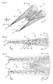
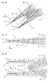
- FIG. 6 and 7 are aberration representations of the projection device 1 according to Fig. 3 to 5 shown, each with two columns are shown.
- the left column refers to the main section in the yz plane and the right column to the main section perpendicular to it in the xz plane, with the image errors in mm for the wavelengths 435, 546 and 656 nm, respectively.
- the relative x and y coordinates are shown side by side.
- the main beam angles are listed in the picture space. For example, in the uppermost illustration in FIG Fig. 6 the x and y coordinates are 0.78 and 0.00.
- the main beam angle is -0.06 ° or 24.0 °.
- Illustrated aberrations Like the comparison of in 8 and 9 Illustrated aberrations with those according to the inventive design of the projection device in 6 and 7 shows an excellent correction of the lateral chromatic aberration, the astigmatism and the Achskoma in the two main sections. While in the conventional solution according to 8 and 9 a lateral deposition of the pixels on the second tilting mirror array 5 of up to 30 .mu.m is present, which prevents pixel-precise assignment of the tilting mirrors K3 and K5 of the two tilting mirror matrices 3, 5 in the case of a typical tilting mirror size of less than 15 .mu.m. In the case of the projection device 1 according to the invention, the lateral deposition of the pixels on the second tilting mirror matrix from the ideal actual position is markedly lower, so that better imaging properties are provided.
- FIGS. 10 to 12 is the same as in FIGS. 3 to 5 the imaging optics 4 of a second embodiment of the projection device 1 according to the invention are shown, again assuming an offner system as a monocentric optical unit 35.
- the imaging optics 4 according to FIGS. 10 to 12 is now in contrast to the embodiment according to FIGS. 3 to 5 not the secondary mirror 14 is designed as a mirror lens and correction element, but the primary mirror 13 and can thus be referred to as a mirror lens 20.
- the rear side 21 of the mirror lens 20 is spherically curved and mirrored and forms the mirror surface 15.
- the mirror 14 facing the secondary mirror 14 of the mirror lens 20 is in turn formed as a freeform surface according to the invention, the curvature of which extends differently in two mutually perpendicular sections and depends on the position on the surface changes.
- the mirror lens may have a thickness of 6 mm and, for example, NFK5 may be used as the material.
- the free-form surface or front side 22 can be described by a polynomial winding according to formula 1, wherein the development coefficients C ij in the following table 2 are given in the same way as in table 1.
- all chromatic and monochromatic aberrations can be corrected at the same time excellent, such as the aberrations in FIGS. 13 and 14 can be seen.
- This is possible even with a low polynomial order of the free-form surface 22 in comparison to the embodiment according to FIG FIGS. 3 to 5 ,
- the freeform surface 22 lies in the intermediate region between close to the field and near the aperture and is therefore particularly suitable for ensuring excellent correction of all image aberrations that occur.
- the image of the imaging optics 4 is practically diffraction-limited and has only extremely small distortions of the pixels in both coordinate directions.
- both the primary mirror 13 and the secondary mirror 14 are each formed as a mirror lens 18, 20, wherein the facing front sides of the lenses 18, 20 are each formed as a free-form surface and the backs 17 and 21 of the two lenses 18 and 20 respectively Formation of spherical primary mirror 13 and spherical secondary mirror 14 are mirrored.
- the two mirrors 13 and 14 form the monocentric optical unit.
- NFK5 may be used, wherein the mirror lens 18 has a thickness of 3 mm and the mirror lens 20 has a thickness of 6 mm.
- FIGS. 20 to 22 a further embodiment of the imaging optics 4 according to a further embodiment of the projection device 1 according to the invention is shown.
- the two mirrors 13 and 14 form an Offner system (they are each spherically curved and their centers of curvature coincide).
- a refractive correction element 23 is arranged, the one facing the illumination modulator 3 front side 24 and a the Illumination modulator 3 facing away from back 25 has.
- the thickness of the correction element 23 is 5 mm and NFK5 was used as the material.
- Both the front side 24 and the rear side 25 are formed as a free-form surface, the curvature of which runs differently in two mutually perpendicular sections and changes depending on the position on the surface.
- the freeform surface of the front side 24 can in turn be described by a polynomial winding according to formula 1.
- the corresponding coefficients are given in Table 3 below.
- the rear side 25 can be described by a polynomial winding according to formula 1.
- the coefficients are given in Table 4 below.
- the local coordinate origin for the surface description of the front side 24 and rear side 25 is derived from the global coordinate origin (intersection of the optical axis of the Offner system with the connecting line between the two modulators 3, 5) by displacement along the z axis by 151 mm (front side 24 ) or 156 mm (back 25).
- the wavefront errors caused by the cover glasses 11, 12 can be almost completely compensated, such as the aberrations in FIGS. 23 and 24 can be seen.
- the image is pixel-precise or tilt-mirror accurate.
- the distortion that is to say the lateral deposition of the pixels on the image modulator 5 from its ideal image position, is less than 5 ⁇ m for all field points in the x and y directions.
- FIGS. 25 to 27 Another modification of the imaging optics 4 is in FIGS. 25 to 27 shown.
- a further correction element 26 is arranged in the beam path between the primary mirror 13 and the image modulator 5.
- the further correction element 26 may, as shown in the illustrations according to FIGS. 25 to 27 shown to be formed as a separate element.
- the two correction elements 23 and 26 are formed as a coherent correction element.
- the two correction elements 23 and 26 or the correction element 23 designed as a single correction element are preferably symmetrical with respect to the yz plane. This symmetrical design has the advantage that the requirement for the positioning accuracy of the correction element 23 and the correction elements 23 and 26 are somewhat reduced and thus the adjustment is simplified.
- the training as the only correction element of advantage since the adjustment of the two correction elements 23, 26 deleted each other and having the positioning of the single correction element relative to the two tilting mirror matrices less critical adjustment tolerances.
- FIGs 30-32 a further embodiment of the imaging optics 4 is shown, which differs from the previous Offner structure.
- this training is created by unfolding an Offner system to the secondary mirror, which is omitted.
- the secondary mirror is a wedge-shaped correction element 27, which takes over together with the free-form mirrors 28 and 29, the corrections of the figure.
- the actual mapping is made only by the two free-form mirrors 28 and 29, which correspond to the primary mirror in an Offner system.
- the two plan deflection mirrors 30 and 31 serve only to be able to attach the two modulators 3, 5 spatially separated.
- the curvatures of the two free-form mirrors 28 and 29 are identical.
- the correction element 27 is designed as achromatized Kittange.
- the illumination modulator 3 is exposed to white light.
- the light source 2 emits colored light.
- it can time-sequentially emit differently colored light, e.g. red, green and blue light.
- a multicolored image can be produced by time-sequential representation of red, green and blue partial color images. It only needs to be done so fast the color change that a viewer can not separate the successive temporally projected partial color images, so that the viewer can perceive only the superposition and thus the multi-color image.
- the time-sequential generation of the differently colored illumination light can be carried out in the usual manner, for example by means of a color wheel 35 (FIG. Fig. 1 ) between the light source 2 and the illumination modulator 3.
- the overlay and color separation can be carried out by means of dichroic layers.
- this embodiment with six modulators is considerably more complicated than the previously described embodiments.
- a brighter color image can be produced.
Landscapes
- Physics & Mathematics (AREA)
- General Physics & Mathematics (AREA)
- Optics & Photonics (AREA)
- Engineering & Computer Science (AREA)
- Multimedia (AREA)
- Signal Processing (AREA)
- Lenses (AREA)
- Projection Apparatus (AREA)
- Mechanical Light Control Or Optical Switches (AREA)
Abstract
Description
- Die vorliegende Erfindung betrifft eine Projektionsvorrichtung mit einer ersten und einer zweiten Kippspiegelmatrix, einer Abbildungsoptik, die die erste Kippspiegelmatrix auf die zweite Kippspiegelmatrix abbildet und einer Projektionsoptik, die von der zweiten Kippspiegelmatrix reflektiertes Licht projiziert, um ein Bild zu erzeugen.
- Bei solchen Projektionsvorrichtungen ist es zur Erzielung von guten Bildqualitäten beim projizierten Bild wesentlich, eine exakte und möglichst fehlerfreie Abbildung der ersten Kippspiegelmatrix auf die zweite Kippspiegelmatrix durchzuführen. Es hat sich jedoch gezeigt, daß selbst bei dem Einsatz von Abbildungsoptiken, die theoretisch eine äußerst genaue 1:1 Abbildung realisieren, immer noch Bildfehler auftreten.
- Ausgehend hiervon ist es Aufgabe der Erfindung, eine Projektionsvorrichtung mit einer ersten und einer zweiten Kippspiegelmatrix, einer Abbildungsoptik, die die erste Kippspiegelmatrix auf die zweite Kippspiegelmatrix abbildet, und einer Projektionsoptik, die von der zweiten Kippspiegelmatrix reflektiertes Licht projiziert, um ein Bild zu erzeugen, so weiterzubilden, daß das projizierte Bild eine verbesserte Qualität aufweist.
- Erfindungsgemäß wird die Aufgabe durch eine Projektionsvorrichtung mit einer ersten und einer zweiten Kippspiegelmatrix, die jeweils eine Mehrzahl von Kippspiegeln und ein die Kippspiegel überdeckendes Deckglas aufweisen, einer Abbildungsoptik, die eine Relays-Optik , die die Kippspiegel der ersten Kippspiegelmatrix auf die Kippspiegel der zweiten Kippspiegelmatrix und somit von Kippspiegeln der ersten Kippspiegelmatrix reflektiertes Licht auf Kippspiegel der zweiten Kippspiegelmatrix abbildet, aufweist, und einer Projektionsoptik, die von Kippspiegeln der zweiten Kippspiegelmatrix reflektiertes Licht projiziert (insbesondere auf eine Projektionsfläche), um ein Bild zu erzeugen, gelöst, wobei die Abbildungsoptik ferner ein Korrekturelement aufweist, das zumindest einen Bildfehler, der durch das schräge Durchlaufen des Lichtes durch die Deckgläser bedingt ist, korrigiert.
- Die Erfinder haben festgestellt, daß das schräge Durchlaufen der Deckgläser der Kippspiegelmatrizen zu unerwünschten Aberrationen bei der Abbildung mittels der Abbildungsoptik führen. So entstehen beim schrägen Durchlaufen der Deckgläser (bis auf Bildfehler höherer Ordnung) genau folgende Bildfehler: chromatische Vergrößerungsdifferenz, (Achs-)Koma, (Achs-)Astigmatismus und Verzeichnung. Alle diese Bildfehler bewirken, daß keine pixelgenaue Zuordnung zwischen der ersten und zweiten Kippspiegelmatrix mehr besteht bzw. daß eine unerwünschte laterale Ablage auf der zweiten Kippspiegelmatrix vorliegt. Dieser Effekt bewirkt, daß bei dem Einsatz von einer Abbildungsoptik, die eine hochgenaue 1:1-Abbildung durchführt, immer noch in unerwünschter Weise Bildfehler auftreten und die Falschlichtreduktion weniger perfekt funktioniert. Es ist auch nicht möglich, auf die Deckgläser zu verzichten und sie müssen eine erhebliche Dicke von typischerweise mehreren Millimetern aufweisen, da die Kippspiegel sich im Vakuum befinden und die Deckgläser dem Druckunterschied zwischen Normaldruck und Vakuum standhalten müssen.
- Die Auswirkung der Bildfehler, die durch das schräge Durchlaufen der Deckgläser auftreten, auf die Bildgüte oder Qualität des projizierten Bildes kann wie folgt charakterisiert werden. Die fehlende pixelgenaue Zuordnung führt generell zu einer Kontrastverschlechterung in der Projektionsabbildung (im projizierten Bild). Dieser Fehler wird insbesondere bei Bildern mit hohen In-Bild-Kontrasten deutlich, da die Abweichung von der pixelgenauen Zuordnung in der Regel feldabhängig ist (inklusive Helligkeitsabfall zum Rand hin). Die chromatische Vergrößerungsdifferenz führt dazu, daß farbabhängig mehr oder weniger Streulicht in der Projektionsabbildung auftritt. Wegen der Feldabhängigkeit dieses Fehlers können sich hier zum Rand hin Farbsäume ergeben.
- Durch Auffinden dieser Fehlerquelle des schrägen Durchlaufes der Deckgläser sowie durch das Vorsehen eines entsprechenden Korrekturelementes wird erfindungsgemäß eine Projektionsvorrichtung bereitgestellt, bei der das projizierte Bild eine verbesserte Qualität aufweist, da erfindungsgemäß alle angegebenen Bildfehler, die aufgrund des schrägen Durchlaufens der Deckgläser auftreten, gleichzeitig korrigiert bzw. vermindert werden können.
- Bei der erfindungsgemäßen Projektionsvorrichtung kann die Relays-Optik eine optische Achse aufweisen, können die Mittelpunkte der Kippspiegel jeder Kippspiegelmatrix jeweils in einer DMD-Ebene liegen und können die Kippspiegelmatrizen so positioniert sein, daß die DMD-Ebenen mit der optischen Achse jeweils einen Winkel von ungleich 90° einschließen. Insbesondere können die beiden Kippspiegelmatrizen so positioniert sein, daß die beiden DMD-Ebenen zusammenfallen. Bei dieser Anordnung kann eine besonders gute Abbildung mittels der monozentrischen Optikeinheit realisiert werden.
- Insbesondere kann die Relays-Optik als monozentrische Optikeinheit als ausgebildet sein.
- Unter einer monozentrischen Optikeinheit wird hier insbesondere ein optisches System verstanden, bei dem sämtliche (brechende und/oder reflektierende) Wirkflächen konzentrisch um einen gemeinsamen Krümmungsmittelpunkt angeordnet sind.
- Unter einer Relays-Optik wird hier insbesondere eine Optik verstanden, die ein achsensenkrechtes Flächenelement invertiert auf sich selbst abbildet. Es ist jedoch auch möglich, die Relays-Optik derart aufgefalten auszubilden, daß die Abbildung des Flächenelementes auf sich selbst nicht mehr vorliegt, aber ohne Auffaltung vorliegen würde. Die monozentrische Optikeinheit bildet ein ganzes Volumenelement um den gemeinsamen Krümmungsmittelpunkt herum (invertiert) in sich ab. Auch die monozentrische Optikeinheit kann natürlich derart ausgebildet sein, daß die Abbildung des Volumenelementes in sich selbst ohne Auffaltung vorliegen würde. Dadurch können die schräg zur optischen Achse der monozentrischen Optikeinheit bzw. der Relays-Optik angeordneten DMD-Ebenen, wenn man den Einfluß der Deckgläser nicht berücksichtigt, verzeichnungsfrei und mit guter Wellenfrontqualität aufeinander abgebildet werden. Die in der Praxis auftretenden Bildfehler aufgrund des schrägen Durchlaufen des Lichtes durch die Deckgläser werden erfindungsgemäß mit dem Korrekturelement korrigiert. Insbesondere für Bildinhalte, die eine räumlich nahe Änderung der Farben und/oder Helligkeiten aufweisen, treten feldabhängige Helligkeitsveränderungen bzw. Farbveränderungen auf. So ändern sich beispielsweise bei der Darstellung von einzelnen, weißen Pixeln auf schwarzem Hintergrund sowohl die Helligkeiten als auch die Farben der "weißen" Pixel über das Bild. Im Idealfall können durch Korrektur bzw. Verminderung der Bildfehler die beschriebenen feldabhängigen Helligkeitsveränderungen bzw. Farbveränderungen so stark verringert bzw. unterdrückt werden, daß sie nicht mehr wahrnehmbar sind.
- Die Relays-Optik bzw. die monozentrische Optikeinheit ist insbesondere als 1:1-Abbildungsoptik ausgebildet.
- Das Korrekturelement kann eine gekrümmte Fläche aufweisen, die als Freiformfläche ausgebildet ist, deren Krümmung in zwei senkrecht zueinander verlaufenden Schnitten unterschiedlich verläuft und sich abhängig von der Position auf der Fläche ändert.
- Ferner kann das Korrekturelement als refraktives Element ausgebildet sein. Das refraktive Element kann eine lokal variierende Dicke aufweisen, die so gewählt ist, daß die gewünschte Korrektur bewirkt wird. Dies kann insbesondere dadurch erreicht werden, daß mittels dem refraktiven Element ein zu dem durch die Deckgläser hervorgerufener Fehler entgegengesetzter Fehler bzw. quasi gleich groß entgegengesetzter Fehler verursacht wird, so daß dadurch die gewünschte Korrektur erzielt wird.
- Ferner kann z.B. eine Fläche des refraktiven Elementes als Freiformfläche ausgebildet sein, deren Krümmung in zwei senkrecht zueinander verlaufenden Schnitten unterschiedlich verläuft und sich abhängig von der Position auf der Fläche ändert. Die andere Fläche kann z.B. sphärisch gekrümmt, plan, asphärisch oder in gleicher Weise wie die eine Fläche als Freiformfläche ausgebildet sein.
- Die Relays-Optik bzw. die monozentrische Optikeinheit kann einen Spiegel mit einer gekrümmten Spiegelfläche aufweisen, der durch eine verspiegelte Seite des refraktiven Elementes gebildet ist. Ferner kann die Projektionsvorrichtung zwei refraktive Elemente aufweisen, die die gewünschte Korrektur durchführen. In diesem Fall kann z.B. die Relays-Optik bzw. die monozentrische Optikeinheit zwei Spiegel mit jeweils einer gekrümmten Spiegelfläche aufweisen, die jeweils durch eine verspiegelte Seite eines der beiden refraktiven Elemente gebildet ist. Natürlich kann das zumindest eine refraktive Element ein separates Bauteil sein, so daß der zumindest eine Spiegel in der Relays-Optik bzw. in der monozentrischen Optikeinheit seinerseits ein separates Bauteil ist.
- Das zumindest eine refraktive Korrekturelement kann so positioniert sein, daß es genau einmal oder genau zweimal von dem Licht durchlaufen wird, das mittels der Relays-Optik bzw. der monozentrischen Optikeinheit von den ersten Kippspiegeln auf die zweiten Kippspiegel abgebildet wird.
- Die Relays-Optik bzw. die monozentrische Optikeinheit kann einen Primärspiegel mit einer konkaven sphärischen Spiegelfläche und einen Sekundärspiegel mit einer konvexen sphärischen Spiegelfläche aufweisen.
- Des weiteren kann die Relays-Optik bzw. die monozentrische Optikeinheit als rein reflektive Optikeinheit, als rein refraktive Optikeinheit oder als katadioptrische Optikeinheit ausgebildet sein.
- Insbesondere kann das Korrekturelement als reflektives Element ausgebildet sein. Mit einem solchen reflektiven Element kann auch eine chromatische Bildfehlerkorrektur durchgeführt werden, sofern die Relays-Optik bzw. die monozentrische Optikeinheit zumindest ein refraktives Element enthält. In diesem Fall wird mittels dem reflektiven Korrekturelement, das bevorzugt feldnah angeordnet ist, der Strahlpfad durch den refraktiven Teil der Relays-Optik bzw. der monozentrischen Optikeinheit in Abhängigkeit vom Feldbündelwinkel gezielt so verändert, daß die hierdurch induzierten chromatischen Aberrationen des refraktiven Elementes (bzw. der entsprechenden refraktiven Flächen) der Relays-Optik bzw. der monozentrischen Optikeinheit die Farbfehler der Deckgläser verringern, wodurch wiederum die Qualität des projizierten Bildes verbessert ist.
- Wenn die Relay-Optik beispielsweise als katadioptrische Optik ausgebildet ist, kann beispielsweise ein Spiegel der Relay-Optik als Freiformfläche ausgelegt sein. In diesem Fall ist das Korrekturelement in den Spiegel der Relay-Optik integriert und somit kein separates Bauelement. Der Freiformanteil, also die Abweichung von der z.B. sphärischen Grundform des Spiegels, bildet in diesem Fall quasi das Korrekturelement.
- Des weiteren kann die Abbildungsoptik und/oder die Relays-Optik bzw. die monozentrische Optikeinheit spiegelsymmetrisch zu genau einer Symmetrieebene ausgebildet sein.
- Das refraktive Element kann als separates refraktives Element ausgebildet sein.
- Des weiteren ist es möglich, daß die Relays-Optik bzw. die monozentrische Optikeinheit zwei Spiegel aufweist, wobei einer der beiden Spiegel als konkaver Spiegel und der andere der beiden Spiegel als konvexer Spiegel ausgebildet ist und der Strahlengang von der ersten Kippspiegelmatrix über den konkaven Spiegel zum konvexen Spiegel und wiederum über den konkaven Spiegel bis zur zweiten Kippspiegelmatrix verläuft.
- Das refraktive Element kann insbesondere als achromatische Kittgruppe ausgebildet sein.
- Insbesondere weist die erfindungsgemäße Projektionsvorrichtung genau zwei (z.B. sphärisch) gekrümmte Spiegel auf. Darüber hinaus kann die erfindungsgemäße Projektionsvorrichtung noch weitere plane Umlenkspiegel enthalten.
- Ferner kann die erfindungsgemäße Projektionsvorrichtung eine Steuereinheit zum Betrieb der Projektionsvorrichtung, eine Lichtquelle (ein- oder mehrfarbig) zum Beleuchten der ersten Kippspiegelmatrix sowie sonstige dem Fachmann bekannte Elemente aufweisen, die zum Betrieb der Projektionsvorrichtung notwendig sind.
- Es wird ferner eine Projektionsvorrichtung mit einer ersten und einer zweiten Kippspiegelmatrix, einer Abbildungsoptik, die die erste Kippspiegelmatrix auf die zweite Kippspiegelmatrix abbildet, und einer Projektionsoptik, die die zweite Kippspiegelmatrix abbildet (insbesondere auf eine Projektionsfläche), um ein Bild zu erzeugen, bereitgestellt, wobei die Abbildungsoptik zwei gekrümmte Spiegel und ein refraktives Element mit zumindest einer gekrümmten Fläche aufweist, wobei von den beiden gekrümmten Spiegelflächen und der gekrümmten refraktiven Fläche zumindest eine Fläche als Freiformfläche ausgebildet ist, deren Krümmung in zwei senkrecht zueinander verlaufenden Schnitten unterschiedlich verläuft und sich abhängig von der Position auf der Fläche ändert.
- Ferner wird eine Projektionsvorrichtung mit einer ersten und einer zweiten Kippspiegelmatrix, einer Abbildungsoptik, die die erste Kippspiegelmatrix auf die zweite Kippspiegelmatrix abbildet, und eine Projektionsoptik, die die zweite Kippspiegelmatrix abbildet (insbesondere auf eine Projektionsfläche), um ein Bild zu erzeugen, bereitgestellt, wobei die Abbildungsoptik zwei gekrümmte Spiegel mit jeweils gekrümmter Spiegelfläche aufweist, wobei zumindest eine der beiden Spiegelflächen als Freiformfläche ausgebildet ist, deren Krümmung in zwei senkrecht zueinander verlaufenden Schnitten unterschiedlich verläuft und sich abhängig von der Position der Spiegelfläche ändert.
- Die Abbildungsoptik der beiden weiteren Projektionsvorrichtungen kann insbesondere so ausgebildet sein, wie bereits beschrieben wurde.
- Es versteht sich, daß die vorstehend genannten und die nachstehend noch zu erläuternden Merkmale nicht nur in den angegebenen Kombinationen, sondern auch in anderen Kombinationen oder in Alleinstellung einsetzbar sind, ohne den Rahmen der vorliegenden Erfindung zu verlassen.
- Nachfolgend wird die Erfindung beispielsweise anhand der beigefügten Zeichnungen, die auch erfindungswesentliche Merkmale offenbart, noch näher erläutert. Es zeigen:
- Fig. 1
- eine schematische Ansicht einer Ausführungsform der erfindungsgemäßen Projektionsvorrichtung;
- Fig. 2
- eine schematische Darstellung zur Erläuterung der Lichtmodulation mit den beiden Kippspiegelmatrizen 3, 5 der Projektionsvorrichtung 1 von
Fig. 1 ; - Fig. 3
- eine perspektivische Ansicht der Abbildungsoptik 4 der Projektionsvorrichtung 1 von
Fig. 1 ; - Fig. 4
- eine Seitenansicht der Abbildungsoptik 4 gemäß
Fig. 3 ; - Fig. 5
- eine Draufsicht der Abbildungsoptik 4 gemäß
Fig. 3 ; - Fig. 6 und 7
- Darstellungen von Bildfehlern der Projektionsvorrichtung von
Fig. 3-5 ; - Fig. 8 und 9
- Darstellungen von Bildfehlern einer Projektionsvorrichtung ohne refraktives Korrekturelement 18;
- Fig. 10
- eine perspektivische Ansicht einer weitern Ausführungsform der Abbildungsoptik 4 der Projektionsvorrichtung von
Fig. 1 ; - Fig. 11
- eine Seitenansicht der Abbildungsoptik 4 gemäß
Fig. 10 ; - Fig. 12
- eine Draufsicht der Abbildungsoptik 4 gemäß
Fig. 10 ; - Fig. 13 und 14
- Darstellungen von Bildfehlern in gleicher Weise wie in
Fig. 6 und 7 für die Projektionsvorrichtung gemäßFig. 10 bis 12 ; - Fig. 15
- eine perspektivische Ansicht einer weiteren Ausführungsform der Abbildungsoptik 4 der Projektionsvorrichtung 1 gemäß
Fig. 1 ; - Fig. 16
- eine Seitenansicht der Abbildungsoptik 4 von
Fig. 15 ; - Fig. 17
- eine Draufsicht der Abbildungsoptik 4 von
Fig. 15 ; - Fig. 18 und 19
- Darstellungen von Bildfehlern in gleicher Weise wie in
Fig. 6 und 7 für die Projektionsvorrichtung gemäßFig. 15-17 ; - Fig. 20
- eine perspektivische Ansicht einer weiteren Ausführungsform der Abbildungsoptik 4 der Projektionsvorrichtung 1 gemäß
Fig. 1 ; - Fig. 21
- eine Seitenansicht der Abbildungsoptik 4 von
Fig. 20 ; - Fig. 22
- eine Draufsicht der Abbildungsoptik 4 von
Fig. 20 ; - Fig. 23 und 24
- Darstellungen von Bildfehlern in gleicher Weise wie in
Fig. 6 und 7 für die Projektionsvorrichtung gemäßFig. 20-22 ; - Fig. 25
- eine perspektivische Ansicht einer weiteren Ausführungsform der Abbildungsoptik 4 der Projektionsvorrichtung 1 von
Fig. 1 ; - Fig. 26
- eine Seitenansicht der Abbildungsoptik 4 von
Fig. 25 ; - Fig. 27
- eine Draufsicht der Abbildungsoptik 4 von
Fig. 25 ; - Fig. 28 und 29
- Darstellungen von Bildfehlern in gleicher Weise wie in
Fig. 6 und 7 für die Projektionsvorrichtung gemäßFig. 25-27 ; - Fig. 30
- eine perspektivische Ansicht einer weiteren Ausführungsform der Abbildungsoptik 4 der Projektionsvorrichtung 1 von
Fig. 1 ; - Fig. 31
- eine Draufsicht der Abbildungsoptik 4 von
Fig. 30 ; - Fig. 32
- eine Seitenansicht der Abbildungsoptik 4 von
Fig. 30 , und - Fig. 33
- eine Darstellung von Bildfehlern für die Projektionsvorrichtung gemäß
Fig. 30-32 . - Bei der in
Fig. 1 schematisch gezeigten Ausführungsform umfaßt die erfindungsgemäße Projektionsvorrichtung 1 zum Projizieren eines Bildes eine Lichtquelle 2, einen Beleuchtungsmodulator 3, eine Abbildungsoptik 4, ein Bildmodulator 5, eine Projektionsoptik 6 sowie eine Steuereinheit 7. - Die beiden Modulatoren 3, 5 sind jeweils als Kippspiegelmatrix ausgebildet, die n x m Kippspiegel (bzw. Mikrospiegel) in Spalten und Zeilen aufweisen, wobei die Kippspiegel voneinander unabhängig in eine erste und in eine zweite Kippstellung gebracht werden können. Beide Kippspiegelmatrizen 3, 5 können gleich ausgebildet sein und/oder die gleiche Anzahl und Anordnung von Kippspiegeln aufweisen.
- Die Abbildungsoptik 4 ist als 1:1-Abbildungsoptik ausgebildet und bildet jeden Kippspiegel des Beleuchtungsmodulators 3 genau auf einen Kippspiegel des Bildmodulators 5 ab, so daß zu jedem Kippspiegel des Beleuchtungsmodulators 3 genau ein Kippspiegel des Bildmodulators 5 zugeordnet ist. Es sind auch andere Zuordnungen der Kippspiegel möglich. So kann zum Beispiel ein Versatz in Zeilenrichtung so vorgesehen sein, daß jeder Kippspiegel des Bildmodulators 5 durch zwei Kippspiegel (jeweils zur Hälfte) des Beleuchtungsmodulators 3 beleuchtet wird.
- Die beiden Modulatoren 3 und 5 werden von der Steuereinheit 7 basierend auf zugeführten Bilddaten BD so angesteuert, daß der Beleuchtungsmodulator 3, der mit dem Licht (z. B. weißem Licht) der Lichtquelle 2 beaufschlagt wird, eine flächig modulierte Lichtquelle für den Bildmodulator 5 ist, mit dem das zu projizierende Bild erzeugt bzw. moduliert wird, das dann mittels der Projektionsoptik 6 auf eine Projektionsfläche 8 projiziert werden kann.
- Der Beleuchtungsmodulator 3 kann so angesteuert werden, daß nur das Licht, das von den Kippspiegeln des Beleuchtungsmodulators reflektiert wird, die nicht schwarzen Bildpixeln (bzw. die den entsprechenden Kippspiegeln) des Bildmodulators 5 zugeordnet sind, auf den Bildmodulator 5 abgebildet wird. Dadurch kann erreicht werden, daß Bildpixel bzw. Kippspiegel des Bildmodulators 5, die schwarze Bildpunkte darstellen sollen, nicht mit Licht beaufschlagt werden (da die zugeordneten Kippspiegel des Beleuchtungsmodulators 3 bzw. das von diesem Kippspiegel reflektierte Licht nicht auf den Bildmodulator 5 abgebildet wird). Dies führt in vorteilhafter Weise dazu, daß der Schwarzpegel (die unerwünschte Resthelligkeit eines schwarzen Bildpunktes im tatsächlichen projizierten Bild) deutlich reduziert werden kann.
- Die Lichtmodulation durch die beiden Kippspiegelmatrizen 3 und 5 wird in Verbindung mit der schematischen Darstellung in
Fig. 2 näher erläutert. - In
Fig. 2 ist stellvertretend für jede Kippspiegelmatrix 3, 5 jeweils nur ein einziger Kippspiegel K3, K5 in seinen beiden möglichen Kippstellungen eingezeichnet, wobei eine Verkippung der Kippspiegelmatrizen 3, 5 um 24° (um die x-Achse, die senkrecht zur Zeichenebene verläuft) relativ zur Abbildungsoptik 4, wie bei den konkreten Ausführungsbeispielen noch detaillierter erläutert wird, schon schematisch dargestellt ist. - Der Kippwinkel der Kippspiegel K3, K5 beträgt ± 12° relativ zur jeweiligen DMD-Ebene 9,10 (Ebene der Mittelpunkte der Kippspiegel K3 bzw. K5), die um die 24° verkippt ist. Ferner ist in der schematischen Darstellung von
Fig. 2 noch jeweils gestrichelt ein Deckglas 11, 12 eingezeichnet. Diese Deckgläser 11,12 sind bei Kippspiegelmatrizen zwingend notwendig, um das Vakuum, in dem sich die Kippspiegel K3, K5 befinden, aufrecht zu erhalten. Die Deckgläser 11 und 12 müssen somit dem Druckunterschied zwischen Normaldruck und Vakuum standhalten und weisen daher in der Regel eine Dicke von mehreren Millimetern auf. Bei den hier beschriebenen Ausführungsformen wird von einer Dicke von 3 mm ausgegangen, wobei als Glasart BK7 verwendet wird. - Die Kippspiegel K3 und K5 sind in
Fig. 2 in einer Schnittdarstellung gezeigt, die so gewählt ist, daß die jeweilige Kippachse der beiden Kippspiegel K3 und K5 senkrecht zur Zeichenebene verläuft. Ferner liegen die beiden DMD-Ebenen 9, 10 in einer gemeinsamen Ebene, was zur besseren Darstellbarkeit inFig. 2 nicht dargestellt ist. - Der Kippspiegel K3 des Beleuchtungsmodulators 3 kann entweder in seiner ersten Kippstellung S1 oder in seiner zweiten Kippstellung S2 stehen. Beide Kippstellungen sind 12°gegenüber der DMD-Ebene 9 geneigt. In
Fig. 2 sind beide Kippstellungen S1 und S2 eingezeichnet. Natürlich kann der Kippspiegel K3 zu einem Zeitpunkt immer nur in einer der beiden Kippstellungen S1 und S2 stehen. Gleiches gilt für den Kippspiegel K5 des Bildmodulators 5. Der Kippspiegel K5 kann entweder in seiner ersten Stellung S3 oder in seiner zweiten Stellung S4 stehen. - Im Betrieb des Projektors 1 wird der Kippspiegel K3 mit Licht L1 der Lichtquelle 2 so beaufschlagt, daß das Licht senkrecht zur DMD-Ebene 9 auf den Kippspiegel K3 trifft. Wenn der Kippspiegel K3 in seiner zweiten Stellung S2 steht, wird das Licht, da der Kippspiegel K3 relativ zur Ebene 9 gegen den Uhrzeigersinn um 12°gekippt ist, unter einem Winkel von 24°zur Einfallsrichtung des Lichtes L1 als sogenanntes Aus-Licht L2 auf eine nicht gezeigte Strahlfalle reflektiert. Das Aus-Licht L2 wird nicht zur Beleuchtung des Bildmodulators 5 verwendet.
- Wenn jedoch der Kippspiegel K3 in seiner ersten Stellung S1 steht, wird das Licht als sogenanntes Ein-Licht L3 unter einem Winkel von 24° relativ zur Einfallsrichtung des Lichtes L1 reflektiert. Dieses Ein-Licht L3 wird, wie nachfolgend noch detaillierter beschrieben wird, mittels der Abbildungsoptik 4 auf den zugeordneten Kippspiegel K5 des Bildmodulators 5 abgebildet. Die Einfallsrichtung des Ein-Lichtes L3 auf den Kippspiegel K5 ist dabei so gewählt, daß das reflektierte Licht L4, wenn der Kippspiegel K5 in seiner ersten Stellung S3 steht, senkrecht zur DMD-Ebene 10 verläuft. Dazu weist das auf den Kippspiegel K5 einfallende Licht L3 einen Winkel von 24° zum Lot auf die DMD-Ebene 10 auf. Dies führt bei der ersten Kippstellung S3 des Kippspiegels K5 zu der gewünschten Reflexion, so daß das Licht L4 mittels der Projektionsoptik 6 auf die Projektionsfläche 8 projiziert werden kann.
- Wenn der zweite Kippspiegel K5 in seiner zweiten Stellung S4 steht, wird das Licht unter einem Winkel von 48° relativ zum Lot auf die DMD-Ebene 10 als Aus-Licht L5 reflektiert. Dieses Aus-Licht L5 wird in eine Strahlfalle (nicht gezeigt) geleitet und wird nicht bei der Bildprojektion auf die Projektionsfläche 8 verwendet.
- In dieser Art und Weise kann mittels der Kippspiegelmatrix 3 die flächig modulierte Lichtquelle bereitgestellt werden, bei der alle Kippspiegel K3 des Beleuchtungsmodulators 3, die auf einen Kippspiegel K5, der einen nicht schwarzen Bildpunkt darstellen soll, des Bildmodulators 5 abgebildet werden, in die erste Kippstellung gebracht werden. Mittels des Bildmodulators 5 können dann die beleuchteten Kippspiegel K5 so in die erste und zweite Kippstellung geschaltet werden, das während einer Dauer T einer Einzelbilddarstellung die gewünschte Helligkeit des entsprechenden Bildpunktes erzeugt wird. Die Helligkeit kann durch das Verhältnis der Zeitdauer, während der der Kippspiegel K5 in seiner ersten Stellung steht und während der der Kippspiegel K5 in seiner zweiten Stellung steht, eingestellt werden. Die Ansteuerung der beiden Modulatoren 3, 5 kann mit pulsweitenmodulierten Steuerdaten erfolgen, die die Steuereinheit 7 basierend auf den zugeführten Steuerdaten BD erzeugt.
- Für eine kontrastreiche Bildprojektion ist es wichtig, daß die Abbildungsoptik 4 effizient ist und minimale Bildfehler wie Verzeichnung oder chromatische Aberrationen aufweist. Da die Deckgläser 11, 12 von dem Ein-Licht L3 jeweils schräg durchlaufen werden, tritt eine laterale Ablage bei der Abbildung des Kippspiegels K3 auf den Kippspiegel K5 auf. Selbst eine relativ geringe laterale Ablage, die typischerweise bis zu 30 µm beträgt und für verschiedene Feldpunkte variiert, führt bei einer typischen Ausdehnung der Kippspiegel K3 und K5 von kleiner als 15 µm zu schlechteren Projektionseigenschaften.
- Um diese schlechteren Projektionseigenschaften beziehungsweise die diese bedingende laterale Ablage der Bildpunkte der zweiten Kippspiegelmatrix 5 zu verringern, weist bei der Ausführungsform gemäß
Figuren 3 bis 5 die Abbildungsoptik 4 eine monozentrische Optikeinheit 35 mit einem Primärspiegel 13 und einem Sekundärspiegel 15 sowie ein refraktives Korrekturelement 18 auf. Die monozentrische Optikeinheit 35, bei der sämtliche (brechende und/oder reflektierende) Wirkflächen konzentrisch um einen gemeinsamen Krümmungsmittelpunkt angeordnet sind, ist hier als sogenanntes Offner-System ausgebildet und weist, wie alle monozentrischen optischen Systeme, generell die Eigenschaft auf, einen kleinen Volumenbereich um den gemeinsamen Krümmungsmittelpunkt mittels einer nahezu fehlerfreien Zwischenabbildung in sich (invertiert) abzubilden. Dadurch ist es möglich, derartige monozentrische Systeme auch als Relays-Optik für schräg zum Strahlengang und zueinander parallel angeordnete Objekt- und Bildfelder einzusetzen. - Da bei handelsüblichen Kippspiegelmatrizen die Kippachse, um die die einzelnen Kippspiegel kippen, gegenüber den Außenkanten der rechteckigen Gesamtmatrix verdreht sind (und zwar typischerweise um 45°) sind die Kippspiegelmatrizen 3 und 5 entsprechend verdreht angeordnet, wie insbesondere
Figuren 3 und 5 zu entnehmen ist, damit die Kippachsen in der x-Richtung verlaufen. Ferner liegt die bereits beschriebene Verkippung der DMD-Ebenen um 24° um die x-Achse vor. - Die Spiegelfläche 15 des Primärspiegels 13 ist eine konkave sphärische Fläche und die Spiegelfläche 16 des Sekundärspiegels 14 ist eine konvexe sphärische Fläche, wobei die beiden Krümmungsmittelpunkte der beiden Spiegelflächen 15 und 16 zusammenfallen. Das zur Korrektur der durch die Deckgläser 11 und 12 bedingten Aberrationen vorgesehene Korrekturelement 18 ist hier als Linse 18 ausgebildet, wobei der Sekundärspiegel 14 auf der Rückseite 17 der Linse 18 angeordnet ist. Die dem Primärspiegel 13 zugewandte Vorderseite 19 der Linse 18 ist als Freiformfläche ausgebildet, deren Krümmung in zwei senkrecht zueinander verlaufenden Schnitten unterschiedlich verläuft und sich abhängig von der Position an der Vorderseite 19 ändert.
- Die Krümmung der Vorderseite 19 kann beispielsweise durch eine Polynomentwicklung gemäß der folgenden Formel 1 beschrieben werden:

- Die Freiformfläche der Vorderseite 19 ist hier spiegelsymmetrisch bezüglich der yz-Ebene ausgebildet, so daß die Entwicklungskoeffizienten Cij der obigen Formel 1 einen von Null verschiedenen Wert aufweist, wenn der Koeffizient Cij eine gerade Potenz von x beschreibt.
- Die Entwicklungskoeffizienten Cij für die Vorderseite 19 der Linse 18 sind in nachfolgender Tabelle angegeben, wobei als Bezeichnung XiYj gewählt ist. Falls i = 0 ist Xi nicht angegeben. Gleiches gilt für j = 0. In diesem Fall ist Yj nicht angegeben. Ferner ist für j = 1 nur Y angegeben. So bezeichnet zum Beispiel X2Y den Entwicklungskoeffizienten C21, Y4 den Entwicklungskoeffizienten C04 und X4Y den Entwicklungskoeffizienten C41.
Y: -3,9260E-03 X2: 8,4604E-03 Y2: 8,4484E-03 X2Y: -2,9354E-07 Y3: -3,0556E-07 X4: 1,7613E-06 X2Y2: 3,5208E-06 Y4: 1,7616E-06 X4Y: -4,0056E-11 X2Y3: -5,8332E-11 Y5: -3,9814E-11 X6: 6,0814E-10 X4Y2: 1,8397E-09 X2Y4: 1,8379E-09 Y6: 6,0026E-10 - Die Spiegellinse 18 weist hier eine Dicke von 6 mm und als Material wird BK7 verwendet. Ferner wird eine numerische Apertur von 0,1 für die Beleuchtung der Kippspiegel K3 und K5 für die vorliegende Ausführungsform und für alle nachfolgenden Ausführungsformen angenommen.
- Aufgrund der unterschiedlichen Krümmungsverläufe der brechenden Vorderseite 19 (bzw. brechende Freiformfläche) in den zwei orthogonalen Hauptschnitten gelingt es gleichzeitig, die Farbquerfehler, den Achsastigmatismus und die Achskoma hervorragend zu korrigieren.
- Da der Sekundärspiegel 15 als Spiegellinse 18 ausgebildet ist, ist die zu bearbeitende Vorderseite 19 klein, so daß Herstellungskosten und Gewicht minimiert werden können. Ferner liegt die gewünschte Justierung zwischen der brechenden Fläche (Vorderseite 19) und der Spiegelfläche 16 des Sekundärspiegels 14 vor.
- In
Fig. 6 und 7 sind Bildfehlerdarstellungen der Projektionsvorrichtung 1 gemäßFig. 3 bis 5 gezeigt, wobei jeweils zwei Spalten dargestellt sind. Die linke Spalte bezieht sich auf den Hauptschnitt in der yz-Ebene und die rechte Spalte auf den Hauptschnitt senkrecht dazu in der xz-Ebene, wobei die Bildfehler in mm jeweils für die Wellenlängen 435, 546 und 656 nm dargestellt sind. Zwischen den entsprechenden Bildfehlerkurven für die beiden Hauptschnitte sind jeweils die relative x- und y-Koordinate nebeneinander angegeben. Darunter sind die Hauptstrahlwinkel im Bildraum aufgeführt. So sind beispielsweise bei der obersten Darstellung inFig. 6 die x- und y-Koordinate 0,78 und 0,00. Der Hauptstrahlwinkel beträgt -0,06° bzw. 24,0°. - In
Fig. 8 und 9 sind zum Vergleich in gleicher Weise wie inFig. 6 und 7 Bildfehler einer Abbildungsoptik gezeigt, die zwar als Offner-System gemäßFig. 3 bis 5 ausgebildet ist, jedoch kein Korrekturelement enthält. - Wie der Vergleich der in
Fig. 8 und 9 dargestellten Bildfehler mit denen gemäß der erfindungsgemäßen Ausbildung der Projektionsvorrichtung inFig. 6 und 7 zeigt, liegt eine ausgezeichnete Korrektur des Farbquerfehlers, des Astigmatismus und des Achskoma in den beiden Hauptschnitten vor. Während bei der herkömmlichen Lösung gemäßFig. 8 und 9 eine laterale Ablage der Bildpunkte auf der zweiten Kippspiegelmatrix 5 von bis zu 30 µm vorliegt, was bei einer typischen Kippspiegelgröße von kleiner 15 µm eine pixelgenaue Zuordnung der Kippspiegel K3 und K5 der beiden Kippspiegelmatrixen 3, 5 verhindert. Bei der erfindungsgemäßen Projektionsvorrichtung 1 ist die laterale Ablage der Bildpunkte auf der zweiten Kippspiegelmatrix von der idealen Ist-Position deutlich geringer, so daß bessere Abbildungseigenschaften bereitgestellt sind. - In
Figuren 10 bis 12 ist in gleicher Weise wie inFiguren 3 bis 5 die Abbildungsoptik 4 einer zweiten Ausführungsform der erfindungsgemäßen Projektionsvorrichtung 1 gezeigt, wobei wiederum von einem Offner-System als monozentrische Optikeinheit 35 ausgegangen wird. Bei der Abbildungsoptik 4 gemäßFiguren 10 bis 12 ist nun im Unterschied zu der Ausführungsform gemäßFiguren 3 bis 5 nicht der Sekundärspiegel 14 als Spiegellinse und Korrekturelement ausgebildet, sondern der Primärspiegel 13 und kann somit als Spiegellinse 20 bezeichnet werden. Die Rückseite 21 der Spiegellinse 20 ist sphärisch gekrümmt und verspiegelt und bildet die Spiegelfläche 15. Die dem Sekundärspiegel 14 zugewandte Vorderseite 22 der Spiegellinse 20 ist wiederum als erfindungsgemäße Freiformfläche ausgebildet, deren Krümmung in zwei senkrecht zueinander verlaufenden Schnitten unterschiedlich verläuft und sich abhängig von der Position auf der Fläche ändert. Die Spiegellinse kann eine Dicke von 6 mm aufweisen und als Material kann beispielsweise NFK5 verwendet werden. Die Freiformfläche bzw. Vorderseite 22 kann durch eine Polynomentwicklung gemäß Formel 1 beschrieben werden, wobei die Entwicklungskoeffizienten Cij in nachfolgender Tabelle 2 in gleicher Art und Weise wie in Tabelle 1 angegeben sind.Y: 1,2255E-03 X2: -9,9112E-05 Y2: -9,6702E-05 X2Y: 2,7816E-08 Y3: 2,6980E-08 X4: -1,1159E-09 X2Y2: -2,3669E-09 Y4: -1,1140E-09 - Bei dieser Ausbildung können alle chromatischen und monochromatischen Bildfehler gleichzeitig hervorragend korrigiert werden, wie den Bildfehlerdarstellungen in
Fig. 13 und 14 zu entnehmen ist. Dies ist sogar mit einer niedrigen Polynomordnung der Freiformfläche 22 möglich im Vergleich zu der Ausführungsform gemäßFiguren 3 bis 5 . Die Freiformfläche 22 liegt im Zwischenbereich zwischen feldnah und aperturnah und ist daher besonders geeignet, um eine hervorragende Korrektur aller auftretender Bildfehler zu gewährleisten. Die Abbildung der Abbildungsoptik 4 ist praktisch beugungsbegrenzt und weist nur äußerst geringe Verzeichnungen der Bildpunkte in beiden Koordinatenrichtungen auf. - In
Figuren 15 bis 17 ist die Abbildungsoptik 4 einer weiteren Ausführungsform der erfindungsgemäßen Projektionsvorrichtung 1 gezeigt. Bei dieser Ausführungsform sind sowohl der Primärspiegel 13 als auch der Sekundärspiegel 14 jeweils als Spiegellinse 18, 20 ausgebildet, wobei die einander zugewandten Vorderseiten der Linsen 18, 20 jeweils als Freiformfläche geformt sind und die Rückseiten 17 und 21 der beiden Linsen 18 und 20 jeweils zur Bildung von sphärischem Primärspiegel 13 und sphärischem Sekundärspiegel 14 verspiegelt sind. Es sind somit zwei refraktive Korrekturelemente vorgesehen. Die beiden Spiegel 13 und 14 bilden die monozentrische Optikeinheit. Als Material der Spiegellinsen 18, 20 kann zum Beispiel NFK5 verwendet werden, wobei die Spiegellinse 18 eine Dicke von 3 mm und die Spiegellinse 20 eine Dicke von 6 mm aufweist. Mit dieser Ausbildung kann eine Verbesserung der Korrektur der Abbildungsoptik 4 im Vergleich zu der Variante gemäßFigur 10 bis 12 erzielt werden, wie z.B. den Bildfehlerdarstellungen inFig. 18 und 19 zu entnehmen ist. - In
Figuren 20 bis 22 ist eine weitere Ausbildung der Abbildungsoptik 4 gemäß einer weiteren Ausführungsform der erfindungsgemäßen Projektionsvorrichtung 1 gezeigt. Bei dieser Ausbildung bilden die beiden Spiegel 13 und 14 ein Offner-System (sie sind jeweils sphärisch gekrümmt und ihre Krümmungsmittelpunkte fallen zusammen). In dem Strahlengang vom Beleuchtungsmodulator 3 bis zum Primärspiegel 13 ist ein refraktives Korrekturelement 23 angeordnet, das eine dem Beleuchtungsmodulator 3 zugewandte Vorderseite 24 und eine dem Beleuchtungsmodulator 3 abgewandte Rückseite 25 aufweist. Die Dicke des Korrekturelementes 23 beträgt 5 mm und als Material wurde NFK5 verwendet. Sowohl die Vorderseite 24 als auch die Rückseite 25 sind als Freiformfläche ausgebildet, deren Krümmung in zwei senkrecht zueinander verlaufenden Schnitten unterschiedlich verläuft und sich abhängig von der Position auf der Fläche verändert. - Die Freiformfläche der Vorderseite 24 kann wiederum durch eine Polynomentwicklung gemäß Formel 1 beschrieben werden. Die entsprechenden Koeffizienten sind in der nachfolgenden Tabelle 3 angegeben.
Y: -4,6015E-01 X2: -1,9111 E-04 Y2: -1,2464E-02 X2Y: 1,7592E-06 Y3: 1,6356E-04 X4: 1,0384E-07 X2Y2: 1,8553E-07 Y4: -1,1638E-06 - In gleicher Weise kann die Rückseite 25 durch eine Polynomentwicklung gemäß Formel 1 beschrieben werden. Die Koeffizienten sind in der nachfolgenden Tabelle 4 angegeben.
Y: -4,3142E-01 X2: -1,7340E-04 Y2: -1,2929E-02 X2Y: 1,0752E-06 Y3: 1,6435E-04 X4: 9,8878E-08 X2Y2: 1,7808E-07 Y4: -1,1118E-06 - Der lokale Koordinatenursprung zur Flächenbeschreibung der Vorderseite 24 und Rückseite 25 geht aus dem globalen Koordinatenursprung (Schnittpunkt der optischen Achse des Offner-Systems mit der Verbindungsgeraden zwischen den beiden Modulatoren 3, 5) lediglich durch Verschiebung entlang der z-Achse um 151 mm (Vorderseite 24) bzw. 156 mm (Rückseite 25) hervor. Somit liegt der Entwicklungspunkt für die Polynomentwicklung der beiden Freiformflächen von Vorderseite und Rückseite 24, 25 außerhalb des optisch genutzten Bereiches der Flächen 24, 25 und auf der optischen Achse der für sich genommenen rotationssymmetrischen Relays-Optik 35 (die durch die beiden Spiegel 13 und 14 gebildete monozentrische Optikeinheit 35).
- Mit einem solchen Korrekturelement 23 können die von den Deckgläsern 11, 12 verursachten Wellenfrontfehler nahezu vollständig kompensiert werden, wie den Bildfehlerdarstellungen in
Fig. 23 und 24 zu entnehmen ist. Die Abbildung ist pixelgenau bzw. kippspiegelgenau. Die Verzeichnung, also die laterale Ablage der Bildpunkte auf dem Bildmodulator 5 von ihrer Idealbildposition ist hierbei für alle Feldpunkte in x- und y-Richtung kleiner als 5 µm. - Eine weitere Abwandlung der Abbildungsoptik 4 ist in
Figuren 25 bis 27 dargestellt. Bei dieser Abwandlung ist neben dem Korrekturelement 23 ein weiteres Korrekturelement 26 im Strahlengang zwischen dem Primärspiegel 13 und dem Bildmodulator 5 angeordnet. Das weitere Korrekturelement 26 kann, wie in den Darstellungen gemäßFiguren 25 bis 27 gezeigt, als separates Element ausgebildet sein. Es ist jedoch auch möglich, daß die beiden Korrekturelemente 23 und 26 als ein zusammenhängendes Korrekturelement ausgebildet sind. Die beiden Korrekturelemente 23 und 26 bzw. das als einziges Korrekturelement ausgebildete Korrekturelement 23 ist bevorzugt symmetrisch zur yz-Ebene. Diese symmetrische Ausführung hat den Vorteil, daß die Anforderung an die Positioniergenauigkeit des Korrekturelementes 23 bzw. der Korrekturelemente 23 und 26 etwas herabgesetzt sind und somit die Justage vereinfacht ist. Natürlich ist die Ausbildung als einziges Korrekturelement von Vorteil, da die Justierung der beiden Korrekturelemente 23, 26 zueinander entfällt und die Positionierung des einzigen Korrekturelementes relativ zu den beiden Kippspiegelmatrizen weniger kritische Justiertoleranzen aufweist. - Mit dieser Ausbildung der Abbildungsoptik 4 kann eine Korrektur der von den Deckgläsern induzierten Aberration auf ein praktisch beugungsbegrenztes Niveau durchgeführt werden, wie den Bildfehlerdarstellungen in
Fig. 28 und 29 zu entnehmen ist. Auch ist eine pixelgenaue Verzeichnungskorrektur möglich. - In
Figuren 30-32 ist eine weitere Ausbildung der Abbildungsoptik 4 gezeigt, die von dem bisherigen Offner-Aufbau abweicht. Man kann sich vorstellen, daß diese Ausbildung durch Auffalten eines Offner-Systems um den Sekundärspiegel entsteht, der dabei entfällt. Anstelle des Sekundärspiegels steht ein keilförmiges Korrekturelement 27, das zusammen mit den Freiformspiegeln 28 und 29 die Korrekturen der Abbildung übernimmt. Die eigentliche Abbildung erfolgt nur durch die beiden Freiformspiegel 28 und 29, die in einem Offner-System dem Primärspiegel entsprechen. Die beiden planen Umlenkspiegel 30 und 31 dienen nur dazu, die beiden Modulatoren 3, 5 räumlich getrennt anbringen zu können. Somit sind die Krümmungen der beiden Freiformspiegel 28 und 29 identisch. Gleiches gilt für die beiden brechenden Freiformflächen 32 und 33 des Korrekturelementes 27. Um Farbfehler zu reduzieren, ist das Korrekturelement 27 als achromatisierte Kittgruppe ausgelegt. - Auch mit diesem Aufbau lassen sich ausgezeichnete Aberrationskorrekturen und eine pixelgenaue Abbildung realisieren, wie den Bildfehlerdarstellungen in
Fig. 33 entnommen werden kann. - Merkmale der beschriebenen Ausführungsformen oder die beschriebenen Ausführungsformen können auch miteinander kombiniert werden.
- Bei der bisherigen Beschreibung wird davon ausgegangen, daß der Beleuchtungsmodulator 3 mit weißem Licht beaufschlagt wird. Jedoch ist es auch möglich, daß die Lichtquelle 2 farbiges Licht abgibt. Insbesondere kann sie zeitsequentiell verschiedenfarbiges Licht abgeben, wie z.B. rotes, grünes und blaues Licht. Dann kann in der dem Fachmann bekannten Weise ein mehrfarbiges Bild durch zeitsequentielle Darstellung von roten, grünen und blauen Teilfarbbildern erzeugt werden. Es muß lediglich der Farbwechsel so schnell durchgeführt werden, daß ein Betrachter die zeitlich nacheinander projizierten Teilfarbbilder nicht mehr trennen kann, so daß der Betrachter nur die Überlagerung und somit das mehrfarbige Bild wahrnehmen kann.
- Die zeitsequentielle Erzeugung des unterschiedlichfarbigen Beleuchtungslichtes kann in üblicher Art und Weise durchgeführt werden, beispielsweise mittels einem Farbrad 35 (
Fig. 1 ) zwischen der Lichtquelle 2 und dem Beleuchtungsmodulator 3. - Natürlich ist es auch möglich, statt nur eines Beleuchtungsmodulators drei Beleuchtungsmodulatoren vorzusehen, die gleichzeitig mit rotem, grünem und blauem Licht beaufschlagt werden. Das rote, grüne und blaue Ein-Licht der drei Modulatoren wird dann überlagert und das überlagerte Ein-Licht wird mittels der Abbildungsoptik 4 farbselektiv auf drei Bildmodulatoren 5 abgebildet. Die Bildmodulatoren modulieren das jeweilige Farbteilbild, das wiederum überlagert und dann mittels der Abbildungsoptik 6 auf die Projektionsfläche 8 projiziert wird.
- Die Überlagerung und Farbtrennung kann mittels dichroitischer Schichten durchgeführt werden. Diese Ausführungsform mit sechs Modulatoren ist natürlich deutlich aufwendiger als die bisher beschriebenen Ausführungsformen. Jedoch kann mit einer solchen Ausführungsform ein helleres Farbbild erzeugt werden.
Claims (15)
- Projektionsvorrichtung mit
einer ersten und einer zweiten Kippspiegelmatrix (3, 5), die jeweils eine Mehrzahl von Kippspiegeln (K3, K5) und ein die Kippspiegel (K3, K5) überdeckendes Deckglas (11, 12) aufweisen,
einer Abbildungsoptik (4), die eine Relays-Optik (35), die die Kippspiegel (K3) der ersten Kippspiegelmatrix (3) auf die Kippspiegel (K5) der zweiten Kippspiegelmatrix (5) und somit von Kippspiegeln (K3) der ersten Kippspiegelmatrix (3) reflektiertes Licht auf Kippspiegel (K5) der zweiten Kippspiegelmatrix (5) abbildet, aufweist,
und einer Projektionsoptik (6), die von Kippspiegel (K5) der zweiten Kippspiegelmatrix (5) reflektiertes Licht projiziert, um ein Bild zu erzeugen,
wobei die Abbildungsoptik (4) ferner ein Korrekturelement (18, 20, 23, 26, 27) aufweist, das zumindest einen Bildfehler, der durch das schräge Durchlaufen des Lichtes durch die Deckgläser (11, 12) bedingt ist, korrigiert. - Projektionsvorrichtung nach Anspruch 1, bei der die Relays-Optik (35) als monozentrische Optikeinheit ausgebildet ist.
- Projektionsvorrichtung nach Anspruch 1 oder 2, bei der die Relays-Optik (35) eine optische Achse aufweist, die Mittelpunkte der Kippspiegel (K3, K5) jeder Kippspiegelmatrix (3, 5) jeweils in einer DMD-Ebene (9, 10) liegen und die Kippspiegelmatrizen (3, 5) so positioniert sind, daß die DMD-Ebenen (9, 10) mit der optischen Achse jeweils einen Winkel von ungleich 90° einschließen.
- Projektionsvorrichtung nach Anspruch 3, bei der die beiden Kippspiegelmatrizen (3, 5) so positioniert sind, daß die beiden DMD-Ebenen (9, 10) zusammenfallen.
- Projektionsvorrichtung nach einem der obigen Ansprüche, bei der das Korrekturelement (18, 20, 23, 26, 27) eine gekrümmte Fläche aufweist, die als Freiformfläche ausgebildet ist, deren Krümmung in zwei senkrecht zueinander verlaufenden Schnitten unterschiedlich verläuft und sich abhängig von der Position auf der Fläche ändert.
- Projektionsvorrichtung nach einem der obigen Ansprüche, bei der das Korrekturelement (18, 20, 23, 26, 27) als refraktives Element ausgebildet ist.
- Projektionsvorrichtung nach Anspruch 6, bei der die Relays-Optik (35) einen Spiegel mit einer gekrümmten Spiegelfläche aufweist, die durch eine verspiegelte Seite des refraktiven Elementes (18, 20) gebildet ist.
- Projektionsvorrichtung nach Anspruch 6, bei der das refraktive Korrekturelement (23, 26) so positioniert ist, daß es von dem von der ersten Kippspiegelmatrix (3) auf die zweite Kippspiegelmatrix (5) abgebildeten Licht genau einmal durchlaufen wird.
- Projektionsvorrichtung nach Anspruch 6 oder 7, bei der das refraktive Korrekturelement (18, 20) so positioniert ist, daß es von dem von der ersten auf die zweite Kippspiegelmatrix (3, 5) abgebildeten Licht genau zweimal durchlaufen wird.
- Projektionsvorrichtung nach einem der obigen Ansprüche, bei der die Relays-Optik (35) einen Primärspiegel (13) mit konkaver sphärischer Spiegelfläche und einen Sekundärspiegel (14) mit konvexer sphärischer Spiegelfläche aufweist.
- Projektionsvorrichtung nach einem der obigen Ansprüche, bei der die Relays-Optik (35) rein reflektiv ausgebildet ist.
- Projektionsvorrichtung nach einem der obigen Ansprüche 1 bis 10, bei der die Relays-Optik (35) als katadioptrische Optik ausgebildet ist.
- Projektionsvorrichtung nach einem der Ansprüche 1 bis 9, bei der Relays-Optik (35) als rein refraktive Optik ausgebildet ist.
- Projektionsvorrichtung nach einem der obigen Ansprüche, bei der das Korrekturelement als reflektives Element ausgebildet ist.
- Projektionsvorrichtung nach einem der obigen Ansprüche, bei der die Relays-Optik (35) spiegelsymmetrisch zu genau einer Symmetrieebene ausgebildet ist.
Applications Claiming Priority (1)
| Application Number | Priority Date | Filing Date | Title |
|---|---|---|---|
| DE102012217329.3A DE102012217329B4 (de) | 2012-09-25 | 2012-09-25 | Projektionsvorrichtung |
Publications (2)
| Publication Number | Publication Date |
|---|---|
| EP2711761A1 true EP2711761A1 (de) | 2014-03-26 |
| EP2711761B1 EP2711761B1 (de) | 2020-11-18 |
Family
ID=49035457
Family Applications (1)
| Application Number | Title | Priority Date | Filing Date |
|---|---|---|---|
| EP13181974.0A Active EP2711761B1 (de) | 2012-09-25 | 2013-08-28 | Projektionsvorrichtung |
Country Status (6)
| Country | Link |
|---|---|
| US (2) | US9097967B2 (de) |
| EP (1) | EP2711761B1 (de) |
| JP (1) | JP5824015B2 (de) |
| BR (1) | BR102013024537A2 (de) |
| DE (1) | DE102012217329B4 (de) |
| ES (1) | ES2863669T3 (de) |
Families Citing this family (15)
| Publication number | Priority date | Publication date | Assignee | Title |
|---|---|---|---|---|
| DE102012217329B4 (de) * | 2012-09-25 | 2024-03-21 | Carl Zeiss Jena Gmbh | Projektionsvorrichtung |
| US9329487B2 (en) * | 2013-08-21 | 2016-05-03 | Manfred Bitter | Objective for EUV microscopy, EUV lithography, and x-ray imaging |
| US9083885B1 (en) * | 2013-11-18 | 2015-07-14 | Google Inc. | Fixed focus camera module with near-field image recognition |
| KR102243106B1 (ko) | 2014-08-20 | 2021-04-22 | 삼성전자 주식회사 | 디스플레이장치 및 그 제어방법 |
| US10067352B2 (en) * | 2015-06-15 | 2018-09-04 | Robert Joe Alderman | 3D image generating lens tool |
| JP2017049438A (ja) * | 2015-09-02 | 2017-03-09 | 株式会社目白67 | 観察装置 |
| DE102016115032A1 (de) * | 2016-08-12 | 2018-02-15 | Carl Zeiss Ag | Projektor zum Projizieren von Bildern und Projektionsverfahren für einen solchen Projektor |
| JP7091875B2 (ja) * | 2017-07-20 | 2022-06-28 | 住友化学株式会社 | 塩、酸発生剤、レジスト組成物及びレジストパターンの製造方法 |
| DE102017217164B4 (de) | 2017-09-27 | 2020-10-15 | Continental Automotive Gmbh | Projektionsvorrichtung zum Erzeugen eines pixelbasierten Beleuchtungsmusters |
| CN108051908B (zh) * | 2017-12-01 | 2019-10-15 | 中国科学院长春光学精密机械与物理研究所 | 一种成像光学系统 |
| JP7233009B2 (ja) * | 2017-12-11 | 2023-03-06 | パナソニックIpマネジメント株式会社 | ヘッドアップディスプレイおよびヘッドアップディスプレイを搭載した移動体 |
| EP3726277B1 (de) | 2017-12-11 | 2025-12-17 | Panasonic Automotive Systems Co., Ltd. | Head-up-anzeige und beweglicher körper mit darauf montierter head-up-anzeige |
| JP2020052342A (ja) | 2018-09-28 | 2020-04-02 | キヤノン株式会社 | 光学機器 |
| JP2021152564A (ja) * | 2020-03-24 | 2021-09-30 | セイコーエプソン株式会社 | 虚像表示装置及び光学ユニット |
| DE102020125572A1 (de) | 2020-09-30 | 2022-03-31 | Carl Zeiss Jena Gmbh | Projektionssystem |
Citations (4)
| Publication number | Priority date | Publication date | Assignee | Title |
|---|---|---|---|---|
| WO2004102973A1 (en) * | 2003-05-14 | 2004-11-25 | Seos Limited | Image display apparatus |
| US20060055897A1 (en) * | 2004-09-15 | 2006-03-16 | Lerner Scott A | Optical relay |
| WO2008068257A1 (fr) * | 2006-12-05 | 2008-06-12 | Thomson Licensing | Dispositif d'affichage d'images par projection a deux etages de modulation |
| DE102008029787A1 (de) * | 2008-06-24 | 2009-12-31 | Carl Zeiss Ag | Projektionssystem |
Family Cites Families (16)
| Publication number | Priority date | Publication date | Assignee | Title |
|---|---|---|---|---|
| US5748365A (en) * | 1996-03-26 | 1998-05-05 | Hughes Electronics | Catadioptric one-to-one telecentric image combining system |
| DE69720458T2 (de) | 1997-10-22 | 2004-02-26 | MAX-PLANCK-Gesellschaft zur Förderung der Wissenschaften e.V. | Programmierbares räumlich lichtmoduliertes Mikroskop und Mikroskopieverfahren |
| CA2402197A1 (en) | 2000-03-15 | 2001-09-20 | Steven Charles Read | Improvements in dmd-based image display systems |
| JP4348409B2 (ja) | 2001-02-27 | 2009-10-21 | ドルビー ラボラトリーズ ライセンシング コーポレイション | 高ダイナミック・レンジ表示装置 |
| DE10127620A1 (de) * | 2001-06-07 | 2002-12-12 | Zeiss Carl Jena Gmbh | Anordnung zum Projizieren eines mehrfarbigen Bildes auf eine Projektionsfläche |
| US6863401B2 (en) | 2001-06-30 | 2005-03-08 | Texas Instruments Incorporated | Illumination system |
| US6779892B2 (en) * | 2002-07-26 | 2004-08-24 | Eastman Kodak Company | Monocentric autostereoscopic optical display having an expanded color gamut |
| JP4158757B2 (ja) | 2003-12-24 | 2008-10-01 | セイコーエプソン株式会社 | 光学表示装置及び投射型表示装置 |
| JP4718883B2 (ja) * | 2005-04-11 | 2011-07-06 | Necディスプレイソリューションズ株式会社 | 投写型表示装置 |
| FR2899980A1 (fr) | 2006-09-27 | 2007-10-19 | Thomson Licensing Sas | Dispositif d'affichage d'images par projection comprenant deux modulateurs spatiaux relies par un systeme relais catadioptrique |
| JP4301304B2 (ja) | 2007-02-13 | 2009-07-22 | セイコーエプソン株式会社 | 画像表示装置 |
| DE102008020858B4 (de) | 2008-04-25 | 2012-09-13 | Carl Zeiss Ag | Projektionssystem für ein optisches Anzeigegerät sowie Head-mounted Display mit einem solchen |
| DE102008029785B4 (de) * | 2008-06-24 | 2019-08-22 | Carl Zeiss Jena Gmbh | Projektionssystem |
| JP5990380B2 (ja) * | 2008-06-24 | 2016-09-14 | カール・ツァイス・アクチェンゲゼルシャフトCarl Zeiss Ag | 投影システム |
| EP2369401B1 (de) * | 2010-03-23 | 2015-09-23 | Max-Planck-Gesellschaft zur Förderung der Wissenschaften e.V. | Optische Modulatorvorrichtung und räumlich-zeitlich lichtmoduliertes Bildgebungssystem |
| DE102012217329B4 (de) * | 2012-09-25 | 2024-03-21 | Carl Zeiss Jena Gmbh | Projektionsvorrichtung |
-
2012
- 2012-09-25 DE DE102012217329.3A patent/DE102012217329B4/de active Active
-
2013
- 2013-08-28 ES ES13181974T patent/ES2863669T3/es active Active
- 2013-08-28 EP EP13181974.0A patent/EP2711761B1/de active Active
- 2013-09-17 JP JP2013191303A patent/JP5824015B2/ja not_active Expired - Fee Related
- 2013-09-25 BR BR102013024537-2A patent/BR102013024537A2/pt not_active IP Right Cessation
- 2013-09-25 US US14/036,244 patent/US9097967B2/en active Active
-
2015
- 2015-06-30 US US14/754,917 patent/US9316892B2/en active Active
Patent Citations (4)
| Publication number | Priority date | Publication date | Assignee | Title |
|---|---|---|---|---|
| WO2004102973A1 (en) * | 2003-05-14 | 2004-11-25 | Seos Limited | Image display apparatus |
| US20060055897A1 (en) * | 2004-09-15 | 2006-03-16 | Lerner Scott A | Optical relay |
| WO2008068257A1 (fr) * | 2006-12-05 | 2008-06-12 | Thomson Licensing | Dispositif d'affichage d'images par projection a deux etages de modulation |
| DE102008029787A1 (de) * | 2008-06-24 | 2009-12-31 | Carl Zeiss Ag | Projektionssystem |
Also Published As
| Publication number | Publication date |
|---|---|
| US9316892B2 (en) | 2016-04-19 |
| JP5824015B2 (ja) | 2015-11-25 |
| US9097967B2 (en) | 2015-08-04 |
| JP2014067031A (ja) | 2014-04-17 |
| EP2711761B1 (de) | 2020-11-18 |
| DE102012217329B4 (de) | 2024-03-21 |
| ES2863669T3 (es) | 2021-10-11 |
| US20140085615A1 (en) | 2014-03-27 |
| DE102012217329A1 (de) | 2014-06-12 |
| US20150301436A1 (en) | 2015-10-22 |
| BR102013024537A2 (pt) | 2014-10-21 |
Similar Documents
| Publication | Publication Date | Title |
|---|---|---|
| EP2711761B1 (de) | Projektionsvorrichtung | |
| EP2294483B1 (de) | Projektionssystem | |
| DE69805645T2 (de) | Anzeigegerät mit einem gitter-lichtventilarray und interferometrisches optisches system | |
| DE69503375T2 (de) | Hochauflösendes subtraktives farbprojektionssystem | |
| DE102010064387B4 (de) | Abbildungssystem und Abbildungsverfahren | |
| DE102012205164A1 (de) | Projektionsdisplay und verfahren zum projizieren eines gesamtbildes | |
| DE112018002005T5 (de) | Bildanzeigevorrichtung | |
| DE3712170A1 (de) | Stereoskopisches display-system | |
| DE112017006990T5 (de) | Head-up-display-vorrichtung | |
| WO2007003563A1 (de) | Projektionsbelichtungsanlage mit einer mehrzahl von projektionsobjektiven | |
| DE102012210808A1 (de) | Head-up Display und Projektionsoptik für ein Head-up Display | |
| DE102012204273A1 (de) | Beleuchtungsoptik für die EUV-Projektionslithografie | |
| DE102009011328A1 (de) | Abbildende Optik | |
| DE102016100252B4 (de) | Projektionssystem für Displayanwendungen | |
| DE102022105039A1 (de) | Wellenfrontmanipulator für Head-up-Display mit holographischem Element zum Erzeugen einer gekippten virtuellen Bildebene | |
| DE102015103707A1 (de) | Projektionsobjektiv und Projektionstyp-Anzeigevorrichtung | |
| DE102004001389B4 (de) | Anordnung und Vorrichtung zur Minimierung von Randverfärbungen bei Videoprojektionen | |
| DE102008029788B4 (de) | Projektionssystem | |
| DE102008029789B4 (de) | Projektionssystem | |
| DE102007046505A1 (de) | Anzeigevorrichtung | |
| DE102008029785B4 (de) | Projektionssystem | |
| EP3978983B1 (de) | Projektionssystem | |
| DE102008029787B4 (de) | Projektionssystem | |
| EP2225610B1 (de) | Verfahren und vorrichtung zum projizieren eines bildes auf eine projektionsfläche | |
| DE102008043395A1 (de) | Projektionsobjektiv für die Lithographie |
Legal Events
| Date | Code | Title | Description |
|---|---|---|---|
| PUAI | Public reference made under article 153(3) epc to a published international application that has entered the european phase |
Free format text: ORIGINAL CODE: 0009012 |
|
| AK | Designated contracting states |
Kind code of ref document: A1 Designated state(s): AL AT BE BG CH CY CZ DE DK EE ES FI FR GB GR HR HU IE IS IT LI LT LU LV MC MK MT NL NO PL PT RO RS SE SI SK SM TR |
|
| AX | Request for extension of the european patent |
Extension state: BA ME |
|
| 17P | Request for examination filed |
Effective date: 20140926 |
|
| RBV | Designated contracting states (corrected) |
Designated state(s): AL AT BE BG CH CY CZ DE DK EE ES FI FR GB GR HR HU IE IS IT LI LT LU LV MC MK MT NL NO PL PT RO RS SE SI SK SM TR |
|
| STAA | Information on the status of an ep patent application or granted ep patent |
Free format text: STATUS: EXAMINATION IS IN PROGRESS |
|
| 17Q | First examination report despatched |
Effective date: 20181010 |
|
| RAP1 | Party data changed (applicant data changed or rights of an application transferred) |
Owner name: CARL ZEISS JENA GMBH |
|
| RIC1 | Information provided on ipc code assigned before grant |
Ipc: G03B 21/14 20060101ALI20200626BHEP Ipc: H04N 5/74 20060101ALN20200626BHEP Ipc: G03B 21/20 20060101ALI20200626BHEP Ipc: G03B 21/28 20060101ALI20200626BHEP Ipc: G02B 17/08 20060101ALI20200626BHEP Ipc: G02B 27/00 20060101AFI20200626BHEP Ipc: G03B 21/00 20060101ALI20200626BHEP Ipc: G02B 26/08 20060101ALN20200626BHEP Ipc: H04N 9/31 20060101ALI20200626BHEP |
|
| GRAJ | Information related to disapproval of communication of intention to grant by the applicant or resumption of examination proceedings by the epo deleted |
Free format text: ORIGINAL CODE: EPIDOSDIGR1 |
|
| STAA | Information on the status of an ep patent application or granted ep patent |
Free format text: STATUS: GRANT OF PATENT IS INTENDED |
|
| GRAP | Despatch of communication of intention to grant a patent |
Free format text: ORIGINAL CODE: EPIDOSNIGR1 |
|
| INTG | Intention to grant announced |
Effective date: 20200813 |
|
| GRAS | Grant fee paid |
Free format text: ORIGINAL CODE: EPIDOSNIGR3 |
|
| GRAA | (expected) grant |
Free format text: ORIGINAL CODE: 0009210 |
|
| STAA | Information on the status of an ep patent application or granted ep patent |
Free format text: STATUS: THE PATENT HAS BEEN GRANTED |
|
| RIN1 | Information on inventor provided before grant (corrected) |
Inventor name: NIETEN, CHRISTOPH Inventor name: PRETORIUS, MARCO Inventor name: RUDOLPH, GUENTER Inventor name: GEISSLER, ENRICO |
|
| AK | Designated contracting states |
Kind code of ref document: B1 Designated state(s): AL AT BE BG CH CY CZ DE DK EE ES FI FR GB GR HR HU IE IS IT LI LT LU LV MC MK MT NL NO PL PT RO RS SE SI SK SM TR |
|
| REG | Reference to a national code |
Ref country code: GB Ref legal event code: FG4D Free format text: NOT ENGLISH |
|
| REG | Reference to a national code |
Ref country code: CH Ref legal event code: EP |
|
| REG | Reference to a national code |
Ref country code: DE Ref legal event code: R096 Ref document number: 502013015304 Country of ref document: DE |
|
| REG | Reference to a national code |
Ref country code: IE Ref legal event code: FG4D Free format text: LANGUAGE OF EP DOCUMENT: GERMAN |
|
| REG | Reference to a national code |
Ref country code: AT Ref legal event code: REF Ref document number: 1336401 Country of ref document: AT Kind code of ref document: T Effective date: 20201215 |
|
| REG | Reference to a national code |
Ref country code: NL Ref legal event code: MP Effective date: 20201118 |
|
| PG25 | Lapsed in a contracting state [announced via postgrant information from national office to epo] |
Ref country code: GR Free format text: LAPSE BECAUSE OF FAILURE TO SUBMIT A TRANSLATION OF THE DESCRIPTION OR TO PAY THE FEE WITHIN THE PRESCRIBED TIME-LIMIT Effective date: 20210219 Ref country code: PT Free format text: LAPSE BECAUSE OF FAILURE TO SUBMIT A TRANSLATION OF THE DESCRIPTION OR TO PAY THE FEE WITHIN THE PRESCRIBED TIME-LIMIT Effective date: 20210318 Ref country code: NO Free format text: LAPSE BECAUSE OF FAILURE TO SUBMIT A TRANSLATION OF THE DESCRIPTION OR TO PAY THE FEE WITHIN THE PRESCRIBED TIME-LIMIT Effective date: 20210218 Ref country code: FI Free format text: LAPSE BECAUSE OF FAILURE TO SUBMIT A TRANSLATION OF THE DESCRIPTION OR TO PAY THE FEE WITHIN THE PRESCRIBED TIME-LIMIT Effective date: 20201118 Ref country code: RS Free format text: LAPSE BECAUSE OF FAILURE TO SUBMIT A TRANSLATION OF THE DESCRIPTION OR TO PAY THE FEE WITHIN THE PRESCRIBED TIME-LIMIT Effective date: 20201118 |
|
| PG25 | Lapsed in a contracting state [announced via postgrant information from national office to epo] |
Ref country code: SE Free format text: LAPSE BECAUSE OF FAILURE TO SUBMIT A TRANSLATION OF THE DESCRIPTION OR TO PAY THE FEE WITHIN THE PRESCRIBED TIME-LIMIT Effective date: 20201118 Ref country code: PL Free format text: LAPSE BECAUSE OF FAILURE TO SUBMIT A TRANSLATION OF THE DESCRIPTION OR TO PAY THE FEE WITHIN THE PRESCRIBED TIME-LIMIT Effective date: 20201118 Ref country code: LV Free format text: LAPSE BECAUSE OF FAILURE TO SUBMIT A TRANSLATION OF THE DESCRIPTION OR TO PAY THE FEE WITHIN THE PRESCRIBED TIME-LIMIT Effective date: 20201118 Ref country code: IS Free format text: LAPSE BECAUSE OF FAILURE TO SUBMIT A TRANSLATION OF THE DESCRIPTION OR TO PAY THE FEE WITHIN THE PRESCRIBED TIME-LIMIT Effective date: 20210318 Ref country code: BG Free format text: LAPSE BECAUSE OF FAILURE TO SUBMIT A TRANSLATION OF THE DESCRIPTION OR TO PAY THE FEE WITHIN THE PRESCRIBED TIME-LIMIT Effective date: 20210218 |
|
| REG | Reference to a national code |
Ref country code: LT Ref legal event code: MG9D |
|
| PG25 | Lapsed in a contracting state [announced via postgrant information from national office to epo] |
Ref country code: HR Free format text: LAPSE BECAUSE OF FAILURE TO SUBMIT A TRANSLATION OF THE DESCRIPTION OR TO PAY THE FEE WITHIN THE PRESCRIBED TIME-LIMIT Effective date: 20201118 |
|
| PG25 | Lapsed in a contracting state [announced via postgrant information from national office to epo] |
Ref country code: LT Free format text: LAPSE BECAUSE OF FAILURE TO SUBMIT A TRANSLATION OF THE DESCRIPTION OR TO PAY THE FEE WITHIN THE PRESCRIBED TIME-LIMIT Effective date: 20201118 Ref country code: SK Free format text: LAPSE BECAUSE OF FAILURE TO SUBMIT A TRANSLATION OF THE DESCRIPTION OR TO PAY THE FEE WITHIN THE PRESCRIBED TIME-LIMIT Effective date: 20201118 Ref country code: RO Free format text: LAPSE BECAUSE OF FAILURE TO SUBMIT A TRANSLATION OF THE DESCRIPTION OR TO PAY THE FEE WITHIN THE PRESCRIBED TIME-LIMIT Effective date: 20201118 Ref country code: SM Free format text: LAPSE BECAUSE OF FAILURE TO SUBMIT A TRANSLATION OF THE DESCRIPTION OR TO PAY THE FEE WITHIN THE PRESCRIBED TIME-LIMIT Effective date: 20201118 Ref country code: EE Free format text: LAPSE BECAUSE OF FAILURE TO SUBMIT A TRANSLATION OF THE DESCRIPTION OR TO PAY THE FEE WITHIN THE PRESCRIBED TIME-LIMIT Effective date: 20201118 Ref country code: CZ Free format text: LAPSE BECAUSE OF FAILURE TO SUBMIT A TRANSLATION OF THE DESCRIPTION OR TO PAY THE FEE WITHIN THE PRESCRIBED TIME-LIMIT Effective date: 20201118 |
|
| REG | Reference to a national code |
Ref country code: DE Ref legal event code: R097 Ref document number: 502013015304 Country of ref document: DE |
|
| PG25 | Lapsed in a contracting state [announced via postgrant information from national office to epo] |
Ref country code: DK Free format text: LAPSE BECAUSE OF FAILURE TO SUBMIT A TRANSLATION OF THE DESCRIPTION OR TO PAY THE FEE WITHIN THE PRESCRIBED TIME-LIMIT Effective date: 20201118 |
|
| PLBE | No opposition filed within time limit |
Free format text: ORIGINAL CODE: 0009261 |
|
| STAA | Information on the status of an ep patent application or granted ep patent |
Free format text: STATUS: NO OPPOSITION FILED WITHIN TIME LIMIT |
|
| REG | Reference to a national code |
Ref country code: ES Ref legal event code: FG2A Ref document number: 2863669 Country of ref document: ES Kind code of ref document: T3 Effective date: 20211011 |
|
| 26N | No opposition filed |
Effective date: 20210819 |
|
| PG25 | Lapsed in a contracting state [announced via postgrant information from national office to epo] |
Ref country code: NL Free format text: LAPSE BECAUSE OF FAILURE TO SUBMIT A TRANSLATION OF THE DESCRIPTION OR TO PAY THE FEE WITHIN THE PRESCRIBED TIME-LIMIT Effective date: 20201118 Ref country code: IT Free format text: LAPSE BECAUSE OF FAILURE TO SUBMIT A TRANSLATION OF THE DESCRIPTION OR TO PAY THE FEE WITHIN THE PRESCRIBED TIME-LIMIT Effective date: 20201118 Ref country code: AL Free format text: LAPSE BECAUSE OF FAILURE TO SUBMIT A TRANSLATION OF THE DESCRIPTION OR TO PAY THE FEE WITHIN THE PRESCRIBED TIME-LIMIT Effective date: 20201118 |
|
| PG25 | Lapsed in a contracting state [announced via postgrant information from national office to epo] |
Ref country code: SI Free format text: LAPSE BECAUSE OF FAILURE TO SUBMIT A TRANSLATION OF THE DESCRIPTION OR TO PAY THE FEE WITHIN THE PRESCRIBED TIME-LIMIT Effective date: 20201118 |
|
| REG | Reference to a national code |
Ref country code: CH Ref legal event code: PL |
|
| PG25 | Lapsed in a contracting state [announced via postgrant information from national office to epo] |
Ref country code: MC Free format text: LAPSE BECAUSE OF FAILURE TO SUBMIT A TRANSLATION OF THE DESCRIPTION OR TO PAY THE FEE WITHIN THE PRESCRIBED TIME-LIMIT Effective date: 20201118 |
|
| REG | Reference to a national code |
Ref country code: BE Ref legal event code: MM Effective date: 20210831 |
|
| PG25 | Lapsed in a contracting state [announced via postgrant information from national office to epo] |
Ref country code: LI Free format text: LAPSE BECAUSE OF NON-PAYMENT OF DUE FEES Effective date: 20210831 Ref country code: CH Free format text: LAPSE BECAUSE OF NON-PAYMENT OF DUE FEES Effective date: 20210831 |
|
| PG25 | Lapsed in a contracting state [announced via postgrant information from national office to epo] |
Ref country code: IS Free format text: LAPSE BECAUSE OF FAILURE TO SUBMIT A TRANSLATION OF THE DESCRIPTION OR TO PAY THE FEE WITHIN THE PRESCRIBED TIME-LIMIT Effective date: 20210318 Ref country code: LU Free format text: LAPSE BECAUSE OF NON-PAYMENT OF DUE FEES Effective date: 20210828 |
|
| PG25 | Lapsed in a contracting state [announced via postgrant information from national office to epo] |
Ref country code: IE Free format text: LAPSE BECAUSE OF NON-PAYMENT OF DUE FEES Effective date: 20210828 Ref country code: BE Free format text: LAPSE BECAUSE OF NON-PAYMENT OF DUE FEES Effective date: 20210831 |
|
| REG | Reference to a national code |
Ref country code: AT Ref legal event code: MM01 Ref document number: 1336401 Country of ref document: AT Kind code of ref document: T Effective date: 20210828 |
|
| PG25 | Lapsed in a contracting state [announced via postgrant information from national office to epo] |
Ref country code: AT Free format text: LAPSE BECAUSE OF NON-PAYMENT OF DUE FEES Effective date: 20210828 |
|
| PG25 | Lapsed in a contracting state [announced via postgrant information from national office to epo] |
Ref country code: HU Free format text: LAPSE BECAUSE OF FAILURE TO SUBMIT A TRANSLATION OF THE DESCRIPTION OR TO PAY THE FEE WITHIN THE PRESCRIBED TIME-LIMIT; INVALID AB INITIO Effective date: 20130828 |
|
| PG25 | Lapsed in a contracting state [announced via postgrant information from national office to epo] |
Ref country code: CY Free format text: LAPSE BECAUSE OF FAILURE TO SUBMIT A TRANSLATION OF THE DESCRIPTION OR TO PAY THE FEE WITHIN THE PRESCRIBED TIME-LIMIT Effective date: 20201118 |
|
| PG25 | Lapsed in a contracting state [announced via postgrant information from national office to epo] |
Ref country code: MK Free format text: LAPSE BECAUSE OF FAILURE TO SUBMIT A TRANSLATION OF THE DESCRIPTION OR TO PAY THE FEE WITHIN THE PRESCRIBED TIME-LIMIT Effective date: 20201118 |
|
| PG25 | Lapsed in a contracting state [announced via postgrant information from national office to epo] |
Ref country code: TR Free format text: LAPSE BECAUSE OF FAILURE TO SUBMIT A TRANSLATION OF THE DESCRIPTION OR TO PAY THE FEE WITHIN THE PRESCRIBED TIME-LIMIT Effective date: 20201118 |
|
| PG25 | Lapsed in a contracting state [announced via postgrant information from national office to epo] |
Ref country code: MT Free format text: LAPSE BECAUSE OF FAILURE TO SUBMIT A TRANSLATION OF THE DESCRIPTION OR TO PAY THE FEE WITHIN THE PRESCRIBED TIME-LIMIT Effective date: 20201118 |
|
| PGFP | Annual fee paid to national office [announced via postgrant information from national office to epo] |
Ref country code: ES Payment date: 20250926 Year of fee payment: 13 |
|
| PGFP | Annual fee paid to national office [announced via postgrant information from national office to epo] |
Ref country code: DE Payment date: 20250820 Year of fee payment: 13 |
|
| PGFP | Annual fee paid to national office [announced via postgrant information from national office to epo] |
Ref country code: GB Payment date: 20250820 Year of fee payment: 13 |
|
| PGFP | Annual fee paid to national office [announced via postgrant information from national office to epo] |
Ref country code: FR Payment date: 20250829 Year of fee payment: 13 |