EP2711715A2 - Sample sorting apparatus and sample sorting method - Google Patents
Sample sorting apparatus and sample sorting method Download PDFInfo
- Publication number
- EP2711715A2 EP2711715A2 EP13185121.4A EP13185121A EP2711715A2 EP 2711715 A2 EP2711715 A2 EP 2711715A2 EP 13185121 A EP13185121 A EP 13185121A EP 2711715 A2 EP2711715 A2 EP 2711715A2
- Authority
- EP
- European Patent Office
- Prior art keywords
- sample
- rack
- container
- sorting apparatus
- entrance
- Prior art date
- Legal status (The legal status is an assumption and is not a legal conclusion. Google has not performed a legal analysis and makes no representation as to the accuracy of the status listed.)
- Withdrawn
Links
Images


Classifications
-
- G—PHYSICS
- G01—MEASURING; TESTING
- G01N—INVESTIGATING OR ANALYSING MATERIALS BY DETERMINING THEIR CHEMICAL OR PHYSICAL PROPERTIES
- G01N35/00—Automatic analysis not limited to methods or materials provided for in any single one of groups G01N1/00 - G01N33/00; Handling materials therefor
- G01N35/02—Automatic analysis not limited to methods or materials provided for in any single one of groups G01N1/00 - G01N33/00; Handling materials therefor using a plurality of sample containers moved by a conveyor system past one or more treatment or analysis stations
- G01N35/026—Automatic analysis not limited to methods or materials provided for in any single one of groups G01N1/00 - G01N33/00; Handling materials therefor using a plurality of sample containers moved by a conveyor system past one or more treatment or analysis stations having blocks or racks of reaction cells or cuvettes
-
- G—PHYSICS
- G01—MEASURING; TESTING
- G01N—INVESTIGATING OR ANALYSING MATERIALS BY DETERMINING THEIR CHEMICAL OR PHYSICAL PROPERTIES
- G01N35/00—Automatic analysis not limited to methods or materials provided for in any single one of groups G01N1/00 - G01N33/00; Handling materials therefor
- G01N35/02—Automatic analysis not limited to methods or materials provided for in any single one of groups G01N1/00 - G01N33/00; Handling materials therefor using a plurality of sample containers moved by a conveyor system past one or more treatment or analysis stations
- G01N35/04—Details of the conveyor system
- G01N2035/046—General conveyor features
- G01N2035/0462—Buffers [FIFO] or stacks [LIFO] for holding carriers between operations
-
- G—PHYSICS
- G01—MEASURING; TESTING
- G01N—INVESTIGATING OR ANALYSING MATERIALS BY DETERMINING THEIR CHEMICAL OR PHYSICAL PROPERTIES
- G01N35/00—Automatic analysis not limited to methods or materials provided for in any single one of groups G01N1/00 - G01N33/00; Handling materials therefor
- G01N35/02—Automatic analysis not limited to methods or materials provided for in any single one of groups G01N1/00 - G01N33/00; Handling materials therefor using a plurality of sample containers moved by a conveyor system past one or more treatment or analysis stations
- G01N35/04—Details of the conveyor system
- G01N2035/046—General conveyor features
- G01N2035/0465—Loading or unloading the conveyor
Landscapes
- Chemical & Material Sciences (AREA)
- Physics & Mathematics (AREA)
- Health & Medical Sciences (AREA)
- Life Sciences & Earth Sciences (AREA)
- Analytical Chemistry (AREA)
- Biochemistry (AREA)
- General Health & Medical Sciences (AREA)
- General Physics & Mathematics (AREA)
- Immunology (AREA)
- Pathology (AREA)
- Chemical Kinetics & Catalysis (AREA)
- Automatic Analysis And Handling Materials Therefor (AREA)
Abstract
Description
- The present invention relates to a sample sorting apparatus that can transfer a sample container from one sample rack to another sample rack, and a sample processing system including the sample sorting apparatus.
- To date, there are known sample processing systems that process samples such as blood and urine. For example, in a sample processing system described in
U.S. Patent Application Publication No. 2012/0009087 A , by a transporting apparatus transporting a sample rack holding sample containers, samples contained in the sample containers are transported to a sample processing apparatus. - Further, in a sample processing system described in Japanese Laid-Open Patent Application No.
2002-040034 2009-222535 - When such a sorting apparatus is applied to a sample processing system described in
U.S. Patent Application Publication No. 2012/0009087 A , it is necessary to individually secure a region in which each sorting apparatus is installed. Therefore, there arises a problem that an installation area for the entire sample processing system is increased. - The scope of the present invention is defined solely by the appended claims, and is not affected to any degree by the statements within this summary.
- A first aspect of the present invention is a sample sorting apparatus used in a sample processing system comprises a sample supplying apparatus, a sample processing apparatus, and a transporting apparatus connected to the sample processing apparatus. The sample sorting apparatus comprises a first entrance for receiving a sample rack from the sample supplying apparatus, a container conveyor configured to take out a sample container from the sample rack received through the first entrance and configured to set the taken out sample container on a sample rack, a first exit for sending the sample rack on which the sample container is set to the transporting apparatus, a second entrance for receiving the sample rack from the transporting apparatus, a second exit for sending the sample rack received through the second entrance to the sample supplying apparatus, and a transporter configured to transport the sample rack from the second entrance to the second exit.
- According to the sample sorting apparatus of the first aspect, a sample container supported by a sample rack is taken out from the sample rack and set on another sample rack. Then the sample container is sent out to a sample processing apparatus through the first exit. The sample container processed by the sample processing apparatus is sent out to the sample supplying apparatus through the second exit using the transporter after being received by the sample sorting apparatus through the second entrance. The sample container sent out through the second exit is arbitrarily sent to the sample sorting apparatus through the first entrance by the sample supplying apparatus. Then the sample rack is used for sorting the sample container again. Accordingly, the sample sorting apparatus of the present aspect achieves sorting of sample containers before sample processing and sorting of sample containers after sample processing by one sample sorting apparatus. Therefore, when the sample sorting apparatus of the present aspect is installed into a sample processing system, it is possible to restrain the increase of an installation area for the entire sample processing system. Further, the sample rack transported from the sample processing apparatus is transported to the sample supplying apparatus by the transporter provided in the sample sorting apparatus, and is transported to the first entrance again through the sample supplying apparatus. Therefore, another return line for transporting the sample container from the sample processing apparatus to the entrance of the sample sorting apparatus is not necessary. Accordingly, compared with providing another return line, it is possible to restrain the increase of an installation area for the entire sample processing system. In this way, according to the sample sorting apparatus of the present aspect, sorting of sample containers before sample processing and sorting of sample containers after sample processing are realized with restraining the increase of an installation area for the entire sample processing system.
- Preferably, the container conveyor transfers the sample container taken out from the sample rack to another sample rack.
- Preferably, the sample sorting apparatus comprises a buffer region for once holding the sample container taken out from the sample rack before the sample container is transferred to another sample rack. Accordingly, since it is possible to selectively set an intended sample container to another sample rack from the buffer region, sorting of the sample rack is executed effectively.
- Preferably, the container conveyor transfers the sample container taken out from the sample rack, to a same sample rack.
- Preferably, the sample sorting apparatus comprises a buffer region for once holding the sample container taken out from the sample rack before the sample container is transferred to a setting position in the same sample rack different from a setting position from which the sample container was taken out.
- Preferably, the first entrance and the second exit are provided in a first side face of a body of the sample sorting apparatus, and the first exit and the second entrance are provided in a second side face of the body of the sample sorting apparatus. Accordingly, since the first entrance and second exit are provided in the same side face (first side face), the construction for transporting a sample rack between the sample sorting apparatus and the sample supplying apparatus can be simplified by arranging the sample supplying apparatus so that the first side face is adjoined. Further, since the first exit and second entrance are provided in the same side face (second side), the construction for transporting a sample rack between the sample sorting apparatus and the sample transporting apparatus can be simplified by arranging the sample transporting apparatus so that the second side face is adjoined.
- Preferably, the second side face is arranged opposite to the first side face, relative to the body of the sample sorting apparatus. Accordingly, the sample sorting apparatus, a sample supplying apparatus and a sample transporting apparatus can be arranged in linearly.
- Preferably, the sample sorting apparatus comprises a container storage part for storing one or more sample containers not supplied to the sample processing apparatus.
- Preferably, the container conveyor conveys, from among one or more sample containers held in the sample rack sent in through the first entrance, one or more sample containers not supplied to the sample processing apparatus, to the container storage part.
- Preferably, the container storage part is configured to be able to be drawn outside, and is arranged so as not to block transportation of sample container(s) on the transporter when the container storage part is drawn outside. Accordingly, also when the sample rack is transported to the second exit from the second entrance, the container storage part can be drawn outside and a sample container can be taken out.
- Preferably, the container storage part is arranged at a higher or lower level, in a vertical direction, than a transport path of the transporter, and at least a part of the container storage part overlaps the transport path of the transporter when viewed from the vertical direction. Accordingly, since the configuration of the sample sorting apparatus in the horizontal direction can be small, it is possible to decrease an installation area for the sample sorting apparatus.
- A second aspect of the present invention is a sample sorting method used in a sample processing system comprising a sample supplying apparatus, a sample processing apparatus, a transporting apparatus connected to the sample processing apparatus, and a sample sorting apparatus. The sample sorting method comprises:receiving a sample rack through a first entrance from the sample supplying apparatus, by the sample sorting apparatus; taking out a sample container from the sample rack received through the first entrance, by the sample sorting apparatus; setting the taken out sample container on a sample rack, by the sample sorting apparatus; sending the sample rack on which the sample container is set, to the transporting apparatus through a first exit, by the sample sorting apparatus; receiving again, through a second entrance, the sample rack sent to the transporting apparatus through the first exit, by the sample sorting apparatus; and sending the sample rack received through the second entrance, to the sample supplying apparatus through a second exit, by the sample sorting apparatus.
- According to the sample sorting method of the second aspect, the same effect as the first aspect is acquired.
- Preferably, the sample sorting apparatus holds the taken out sample container once in a buffer region before setting the sample container on a sample rack.
- Preferably, the sample sorting apparatus transfers the sample container taken out from the sample rack to another sample rack.
- Preferably, the sample sorting apparatus transfers the sample container taken out from the sample rack to a setting position in a same sample rack different from a setting position from which the sample container was taken out.
-
-
FIG. 1 shows a structure of a sample processing system according to an embodiment viewed from above; -
FIG. 2 shows structures of a sample container and a sample rack according to an embodiment; -
FIG. 3 shows a structure of the inside of a sample sorting apparatus according to an embodiment viewed from above; -
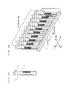
FIG. 4 is a perspective view showing external structures of a feeding unit, the sample sorting apparatus, a relay unit, a preprocessing unit, and a collection unit according to an embodiment; -
FIG. 5 shows side views of a structure of the sample sorting apparatus according to an embodiment, and a plan view showing a positional relationship between a storage part and a transporter viewed from the vertical direction; -
FIG. 6 shows structures of the feeding unit, the relay unit, the preprocessing unit and the collection unit according to an embodiment viewed from above; -
FIG. 7 shows an outline of the configuration of the feeding unit, the sample sorting apparatus, and a transport controller according to an embodiment; -
FIG. 8 shows views for explaining transport routes of a sample rack according to an embodiment; -
FIG. 9 is a perspective view showing external structures of the feeding unit, the sample sorting apparatus, the relay unit, the preprocessing unit, and the collection unit according tomodification 1; -
FIG. 10 shows side views of a structure of the sample sorting apparatus according tomodification 1, and a plan view showing a positional relationship between the storage part and the transporter viewed from the vertical direction; -
FIG. 11 is a perspective view showing external structures of the feeding unit, the sample sorting apparatus, the relay unit, the preprocessing unit, and the collection unit according tomodification 2; -
FIG. 12 shows side views of a structure of the sample sorting apparatus according tomodification 2; -
FIG. 13 shows side views of a structure of the sample sorting apparatus according to another modification; and -
FIG. 14 shows a structure of the sample processing system according to another modification viewed from above. - The preferred embodiments of the present invention will be described hereinafter with reference to the drawings.
-
FIG. 1 shows a structure of asample processing system 1 viewed from above. - The
sample processing system 1 according to the present embodiment includes afeeding unit 21, asample sorting apparatus 22, arelay unit 23, a preprocessingunit 24, acollection unit 25,transporting units 31 to 33,blood cell analyzers smear preparing apparatus 63, and atransport controller 7. Theblood cell analyzer 61 includes aninformation processing unit 51 and ameasurement unit 41. Theblood cell analyzer 62 includes aninformation processing unit 52 and ameasurement unit 42. Thesample processing system 1 is communicably connected to ahost computer 8 via a communication network. - The
feeding unit 21, thesample sorting apparatus 22, therelay unit 23, the preprocessingunit 24, thecollection unit 25, and the transportingunits 31 to 33 are arranged adjacent to each other in the left-right direction such that a sample rack L can be transported therebetween. Further, each of the units and apparatus is configured such that a plurality of sample racks L, each capable of holding ten sample containers T, can be placed thereon, and such that each sample rack L can be transported along the arrows shown inFIG. 1 . -
FIGS. 2A and 2B show structures of a sample container T and a sample rack L, respectively.FIG. 2A is a perspective view showing an external view of a sample container T, andFIG. 2B is a perspective view showing an external view of a sample rack L holding ten sample containers T.FIG. 2B also shows the orientation (front, rear, left, and right directions shown inFIG. 1 ) of the sample rack L when it is transported. - With reference to
FIG. 2A , the sample container T is a tubular container made of glass or synthetic resin having translucency, and its upper end is open. A bar code label T1 is attached to a lateral surface of the sample container T. A bar code including a sample ID is printed on the bar code label T1. The sample container T contains a whole blood sample collected from a patient, and the opening at the upper end thereof is sealed with a rubber cap T2. With reference toFIG. 2B , a bar code label L1 is attached to a lateral surface on the rear side of the sample rack L. A bar code including a rack ID is printed on the bar code label L1. Further, holders capable of vertically holding ten sample containers T are formed in the sample rack L. - With reference back to
FIG. 1 , when starting measurement of sample(s), a user sets one or more sample containers T each containing a sample on a sample rack L, and places this sample rack L in thefeeding unit 21. When supplying an empty sample rack L to anempty rack stocker 110 of thesample sorting apparatus 22, the user places the empty sample rack L in thefeeding unit 21. The sample rack L placed in thefeeding unit 21 is transported rearward, and sent out to thesample sorting apparatus 22. - The
sample sorting apparatus 22 first performs a process by a bar code unit B, with respect to the sample rack L that has been sent out from thefeeding unit 21 to thesample sorting apparatus 22. Specifically, the bar code unit B reads a rack ID from the bar code label L1 of the sample rack L, and reads a sample ID from the bar code label T1 of each sample container T. Thesample sorting apparatus 22 transmits each sample ID read by the bar code unit B to thehost computer 8 via thetransport controller 7. Based on a measurement order set for each sample, an analysis result of the sample, and the like, thehost computer 8 generates information (hereinafter referred to as "transfer information") for transferring its corresponding sample container T within thesample sorting apparatus 22. Then, thesample sorting apparatus 22 receives the transfer information from thehost computer 8 via thetransport controller 7. - Subsequently, the
sample sorting apparatus 22 transfers sample container(s) T held in the sample rack L, into abuffer rack 120, archive racks R1, and a sorting rack R2, in accordance with the received transfer information. Further, thesample sorting apparatus 22 transfers sample container(s) T held in thebuffer rack 120 into a sample rack L as appropriate. Then, this sample rack L is sent out to therelay unit 23. In a case where the sample container(s) T are all taken out and the sample rack L has become empty, and in a case where the sample rack L has been empty from the beginning, this sample rack L will be stocked in theempty rack stocker 110 if theempty rack stocker 110 has a vacancy, or is sent out to therelay unit 23 if theempty rack stocker 110 is full. - When the sample rack L sent out from the
sample sorting apparatus 22 to therelay unit 23 is to be transported leftward, it is sent out to thepreprocessing unit 24, and when the sample rack L is to be transported rightward, it is transported forward in therelay unit 23 to be sent out to thesample sorting apparatus 22. The sample rack L sent out from therelay unit 23 to thepreprocessing unit 24 is transported forward in thepreprocessing unit 24, and then, sent out to the transportingunit 31. - Each of the transporting
units 31 to 33 transports a sample rack L sent out from the upstream side, in accordance with an instruction from thetransport controller 7. Specifically, each of the transportingunits 31 to 33 transports, in a case where processing is performed in its corresponding unit or apparatus, a sample rack L sent out from the upstream side, rearward, to a front position facing its corresponding unit or apparatus. In a case where processing is performed neither in themeasurement unit 41 nor 42, each of the transportingunits - Each of the
measurement units information processing units measurement units information processing units host computer 8 and transmit analysis results to thehost computer 8. - The
smear preparing apparatus 63 aspirates, at its front position, a sample from a sample container T held in a sample rack L, and prepares a smear of the aspirated sample. Further, thesmear preparing apparatus 63 is communicably connected to thehost computer 8, and transmits to thehost computer 8 information indicating that smear preparation has been completed. - When the processing by each of the
measurement units smear preparing apparatus 63 has been completed, and there is no need to perform processing on the downstream side any more, each sample rack L is transported forward in the transporting unit by which the sample rack L is being transported, and then sent out to the upstream side by this transporting unit. In this manner, each sample rack L is sequentially transported in the upstream direction. - The sample rack L which has been sequentially transported from the transporting
units 31 to 33 to the upstream side is further transported rightward by the preprocessingunit 24 and therelay unit 23, and then sent out to thesample sorting apparatus 22. Thesample sorting apparatus 22 sends out the sample rack L sent in from therelay unit 23, to thefeeding unit 21. - The sample rack L sent out from the
sample sorting apparatus 22 to thefeeding unit 21 is transported rearward in thefeeding unit 21, and is sent out to thesample sorting apparatus 22 again. Also in this case, similarly to the above, reading by the bar code unit B is performed, and thesample sorting apparatus 22 receives transfer information from thehost computer 8, and transfers sample container(s) T held in the sample rack L, in accordance with the received transfer information. - Thus, a sample container T that needs neither retests by the
measurement units smear preparing apparatus 63 again (hereinafter simply referred to as "retesting") and that does not need processing performed in an apparatus other than thesample processing system 1 is transferred to one of the archive racks R1, in accordance with its transfer information. A sample container T that does not need retesting but needs processing in an apparatus other than thesample processing system 1 is transferred to the sorting rack R2. A sample container T that needs retesting is transferred to a sample rack L as appropriate, similarly to the above, and then, is sent out to therelay unit 23. The processing of a sample container T by thesample processing system 1 is completed, by the sample container T being transferred to one of the archive racks R1 or the sorting rack R2. - An empty sample rack L sent out from the
sample sorting apparatus 22 to therelay unit 23 is transported forward in therelay unit 23, and then sent out to thesample sorting apparatus 22. Thesample sorting apparatus 22 sends out the empty sample rack L that has been sent in from therelay unit 23, to thefeeding unit 21. The empty sample rack L sent out from thesample sorting apparatus 22 to thefeeding unit 21 is transported rightward by thefeeding unit 21, to be sent out to thecollection unit 25. Then, this sample rack L is transported rearward in thecollection unit 25 to be housed in thecollection unit 25. Thus, transportation of the sample rack L is completed. - The
transport controller 7 is communicably connected to thefeeding unit 21, thesample sorting apparatus 22, therelay unit 23, the preprocessingunit 24, thecollection unit 25, and the transportingunits 31 to 33, and controls transporting operations of a sample rack L performed by these. Thehost computer 8 has stored therein, associated with each sample ID, a measurement order of the sample corresponding to the sample ID, analysis results of this sample, and the like. Moreover, thehost computer 8 retains a rule for transferring a sample container T within thesample sorting apparatus 22. -
FIG. 3 shows a structure of the inside of thesample sorting apparatus 22 viewed from above. - The
sample sorting apparatus 22 is provided with acontainer conveyor 130 for conveying a sample container T within thesample sorting apparatus 22. Thecontainer conveyor 130 includes: twoguides 131 fixed inside thesample sorting apparatus 22 and extending in the front-rear direction; aguide 132 extending in the left-right direction and slidable in the front-rear direction along theguides 131; a slidingpart 133 slidable in the left-right direction along theguide 132; an ascending/descendingpart 134 set in the slidingpart 133 and capable of ascending/descending relative to the slidingpart 133; agripper 135 set at the lower end of the ascending/descendingpart 134 and capable of gripping a sample container T; and a mechanism for driving these parts. It should be noted that theguides 131 are located at a higher level than atransporter 140. - The
buffer rack 120 is provided with 60holders 121. In thebuffer rack 120, aregion 120a including 30holders 121 on the rear side and aregion 120b including 30holders 121 on the front side are set. Each archive rack R1 is provided with 125 holders R11, and the sorting rack R2 is provided with 250 holders R21. - A sample rack L sent out from the
feeding unit 21 is transported leftward by abelt 141 of thetransporter 140 to be located at a position P1 facing the bar code unit B. The bar code unit B reads the rack ID and each sample ID. As described above, thesample sorting apparatus 22 transmits each sample ID that has been read, to thehost computer 8 and receives transfer information from thehost computer 8. Upon completion of reading by the bar code unit B, the sample rack L is transported leftward to be located at a position P2. With the sample rack L being located at the position P2, sample container(s) T held in this sample rack L are transferred by thecontainer conveyor 130, in accordance with their transfer information. - The transfer information includes a transfer destination within the
sample sorting apparatus 22 of a sample container T. Specifically, when the transportation destination of a sample container T is themeasurement unit 41, the transfer information is "no transfer". When the transportation destination of a sample container T is themeasurement unit 42, the transfer information is "buffer rack region 120a". When the transportation destination of a sample container T is thesmear preparing apparatus 63, the transfer information is "buffer rack region 120b". When the transportation destination of a sample container T is an apparatus that is none of themeasurement units measurement units smear preparing apparatus 63, and another apparatus, and no other process is scheduled, the transfer information is "archive rack". When the transfer information of a sample container T is "buffer rack region 120a", "buffer rack region 120b", "archive rack", or "sorting rack", this sample container T is accordingly transferred to aholder 121 in theregion 120a of thebuffer rack 120, aholder 121 of theregion 120b of thebuffer rack 120, a holder R11 of one of the archive racks R1, or a holder R21 of the sorting rack R2. - In a case where a sample rack L from which all the sample container(s) T have been taken out at the position P2 and has become empty, or a sample rack L that has been empty from the beginning and has been transported from the position P1 to the position P2 is to be conveyed to the
empty rack stocker 110, the sample rack L is pushed out to a position P3, which is in a front portion of theempty rack stocker 110, by the front side face of this sample rack L being pushed by a rack pushing-outmechanism 151. On the other hand, an empty sample rack L located at the position P3 is sent to the position P2, by the rear side face of the rearmost sample rack L in theempty rack stocker 110 being pushed by a rack sending-inmechanism 111. - Into an empty sample rack L located at the position P2, sample container(s) T held in the
region buffer rack 120 are transferred by thecontainer conveyor 130 as appropriate. When the sample rack L located at the position P2 is to be conveyed to the downstream side, the sample rack L is transported leftward by thebelt 141 to be located at a position P4. The sample rack L located at the position P4 is transported leftward by thebelt 141, to be sent out to therelay unit 23. - Here, a sample rack L that holds only sample container(s) T that were not transferred at the position P2 is transported to the
measurement unit 41, and is subjected to measurement by themeasurement unit 41. Meanwhile, a sample rack L into which sample container(s) T held in theregion 120a of thebuffer rack 120 have been transferred is transported to themeasurement unit 42, and is subjected to measurement by themeasurement unit 42. Further, a sample rack L into which sample container(s) T held in theregion 120b of thebuffer rack 120 have been transferred is transported to thesmear preparing apparatus 63, and is subjected to smear preparation by thesmear preparing apparatus 63. That is, theregions measurement unit 42 and thesmear preparing apparatus 63, respectively, and sample container(s) T that remain in a sample rack L without being transferred to these regions are transported to themeasurement unit 41, and are subjected to measurement by themeasurement unit 41. - Next, a sample rack L sent in from the
relay unit 23 to atransporter 160 is transported rightward by abelt 161 or abelt 162 of thetransporter 160, and is located at a position P5 or a position P6. The sample rack L located at the position P6 is then located at the position P5 by the rear side face of the sample L being pushed by a rack pushing-outmechanism 152. The sample rack L located at the position P5 is transported rightward by thebelt 161, to be sent out to thefeeding unit 21. -
FIG. 4 is a perspective view showing external structures of thefeeding unit 21, thesample sorting apparatus 22, therelay unit 23, the preprocessingunit 24, and thecollection unit 25. - In front portions of the
feeding unit 21, thesample sorting apparatus 22, therelay unit 23, the preprocessingunit 24, and thecollection unit 25, covers C1 to C5 are provided so as to prevent a user from touching a sample rack L that is being transported. Each of the covers C1 to C5 is configured to be able to be turned forward. Further, thesample sorting apparatus 22 is provided with afront cover 22a, at the front face thereof. The user can access the inside of thesample sorting apparatus 22, by opening thefront cover 22a upward. - Each archive rack R1 and the sorting rack R2 are respectively housed in
trays sample sorting apparatus 22, an opening S1 is provided so as to be located to the front of six pairs of the archive rack R1 and thetray 171, and the sorting rack R2 and the tray 171 (hereinafter referred to as "storage part"). Accordingly, the user can draw thetrays trays - Each of
FIGS. 5A and 5B shows a side view of the structure of thesample sorting apparatus 22. - With reference to
FIG. 5A , at the right end of thesample sorting apparatus 22, there is provided aside face 22b that is parallel to a plane extending in the front-rear direction and the up-down direction. Theside face 22b is provided with an inlet G1 for sending in a sample rack L sent out from thefeeding unit 21, to thebelt 141, and an exit G4 for sending out a sample rack L from thebelt 161 to thefeeding unit 21. With reference toFIG. 5B , at the left end of thesample sorting apparatus 22, there is provided aside face 22c that is parallel to a plane extending in the front-rear direction and the up-down direction. Theside face 22c is provided with an outlet G2 for sending out a sample rack L from thebelt 141 to therelay unit 23, and an entrance G3 for sending in a sample rack L sent out from therelay unit 23, to thebelt - Further, the storage part is located at a higher level than the
transporter 160, the sample rack L transported on thetransporter 160, and the sample container(s) T held in this sample rack L, and the cover C2. Therefore, the user can draw thetrays transporter 160. -
FIG. 5C is a plan view showing a positional relationship between the storage part and thetransporter 160 viewed from the vertical direction. - When a region of the
transporter 160 corresponding to the width in the left-right direction of the storage part is defined as a region A1, the storage part does not overlap the region A1. Therefore, even when thebelt transporter 160 is stopped due to a failure or the like, the user can easily take out the sample container(s) T and the sample rack L stopped on thebelt belt -
FIG. 6 shows the structures of thefeeding unit 21, therelay unit 23, the preprocessingunit 24, and thecollection unit 25 viewed from above. It should be noted that, the inside of thesample sorting apparatus 22 is not shown for convenience. - In a rear portion and a front portion of the
feeding unit 21, positions P211 and P212 are set, respectively. As also shown inFIG. 4 , to the left of the position P211, a cutout N1 is formed, and to the left and right of the position P212, cutouts N2 and N3 are formed, respectively The cutouts N1 and N2 are connected to the inlet G1 and the exit G4 of thesample sorting apparatus 22, respectively, and are configured to allow transportation of a sample rack L therethrough. - When a sample rack L is located in a
transport path 21a of thefeeding unit 21, this sample rack L is then located at the position P211 by a rack sending-inmechanism 21b. The sample rack L located at the position P211 is sent out to thesample sorting apparatus 22 via the cutout N1 by a rack sending-outmechanism 21 c. On the other hand, a sample rack L sent out from thesample sorting apparatus 22 to thefeeding unit 21 is located at the position P212 via the cutout N2 by abelt 21d. In a case where sample container(s) T are supported in the sample rack L located at the position P212, this sample rack L is pushed out to thetransport path 21a by a rack pushing-outmechanism 21e. In a case where the sample rack L located at the position P212 is empty, this sample rack L is sent out to thecollection unit 25 via the cutout N3 by thebelt 21d. - In a rear portion and a front portion of the
relay unit 23, and in a front portion of atransport path 23c, positions P231, P232, and P233 are set, respectively. To the right and left of the position P231, cutouts N4 and N5 are formed, respectively. To the left and right of the position P232, cutouts N6 and N7 are formed, respectively. To the right of the position P233, a cutout N8 is formed. The cutout N4 is continued to the outlet G2 of thesample sorting apparatus 22, and is configured to allow transportation of a sample rack L therethrough. The cutouts N7 and N8 are continued to the entrance G3 of thesample sorting apparatus 22, and are configured to allow transportation of a sample rack L therethrough. - A sample rack L sent out from the
sample sorting apparatus 22 to therelay unit 23 is located at the position P231 via the cutout N4 by abelt 23a. In a case where sample container(s) T are held in the sample rack L located at the position P231, this sample rack L is transported to thepreprocessing unit 24 via the cutout N5 by thebelt 23a. In a case where the sample rack L located at the position P231 is empty, this sample rack L is pushed out to thetransport path 23c by a rack pushing-outmechanism 23b, then located at the position P233 by a rack sending-inmechanism 23d, and then sent out to thesample sorting apparatus 22 via the cutout N8 by a rack sending-outmechanism 23e. On the other hand, a sample rack L sent out from the preprocessingunit 24 to therelay unit 23 is located at the position P232 via the cutout N6, to be sent out to thesample sorting apparatus 22 via the cutout N7 by abelt 23f. - Similarly to the
relay unit 23, the preprocessingunit 24 is provided with cutouts N9 to N12. A sample rack L sent out from therelay unit 23 to thepreprocessing unit 24 is located at a position P241 via the cutout N9 by abelt 24a, pushed out to atransport path 24c by a rack pushing-outmechanism 24b, then located at a position P243 by a rack sending-inmechanism 24d, and then sent out to the transportingunit 31 via the cutout N10 by a rack sending-outmechanism 24e. On the other hand, a sample rack L sent out from the transportingunit 31 to thepreprocessing unit 24 is located at a position P242 via the cutout N11, to be sent out to therelay unit 23 via the cutout N12 by abelt 24f. - In a front portion of the
collection unit 25, a position P251 is set. To the left of the position P251, a cutout N13 is formed. The cutout N13 is continued to the cutout N3 of thefeeding unit 21, and is configured to allow transportation of a sample rack L therethrough. A sample rack L sent out from thefeeding unit 21 to thecollection unit 25 is located at the position P251 via the cutout N13 by abelt 25a, pushed out to atransport path 25c by a rack pushing-outmechanism 25b, transported rearward by a rack sending-inmechanism 25d, and then housed in thetransport path 25c. -
FIG. 7 shows an outline of the configuration of thefeeding unit 21, thesample sorting apparatus 22, and thetransport controller 7. - The
sample sorting apparatus 22 includes acontroller 221, acommunication section 222, the bar code unit B, thecontainer conveyor 130, adriving section 223, asensor section 224, and adisplay input section 225. Thecontroller 221 controls these components in thesample sorting apparatus 22 and receives signals outputted from these components in thesample sorting apparatus 22. Further, thecontroller 221 communicates with thetransport controller 7 via thecommunication section 222. - The
driving section 223 includes mechanisms for driving thebelts mechanisms mechanism 111 shown inFIG. 3 , and in addition, a mechanism for transporting a sample rack L on thesample sorting apparatus 22, and a drive source for driving these mechanisms. Thesensor section 224 includes sensors for detecting a sample rack L located at the positions P1 to P6. - The
feeding unit 21 includes acontroller 211, acommunication section 212, adriving section 213, and asensor section 214. Thecontroller 211 controls these components in thefeeding unit 21 and receives signals outputted from these components in thefeeding unit 21. Further, thecontroller 211 communicates with thetransport controller 7 via thecommunication section 212. It should be noted that therelay unit 23, the preprocessingunit 24, and thecollection unit 25 have configurations similar to that of thefeeding unit 21. - The
transport controller 7 includes acontroller 701, acommunication section 702, ahard disk 703, and adisplay input section 704. Thecontroller 701 communicates with thefeeding unit 21, thesample sorting apparatus 22, therelay unit 23, the preprocessingunit 24, thecollection unit 25, the transportingunits 31 to 33, and thehost computer 8, via thecommunication section 702. - Each of
FIGS. 8A to 8D is a view for explaining transport routes of a sample rack L. InFIGS. 8A to 8D , transport of a sample rack L is shown by solid arrows, and transfer of a sample container T is shown by dashed arrows. Further, only the vicinity of thesample sorting apparatus 22 in thesample processing system 1 is shown inFIGS. 8A to 8D . - With reference to
FIG. 8A , when a sample rack L holding sample container(s) T is placed in thefeeding unit 21, this sample rack L is transported from thefeeding unit 21 to thesample sorting apparatus 22. Thesample sorting apparatus 22 transfers sample container(s) T held in this sample rack L. As a result, sample container(s) T are accordingly transferred to thebuffer rack 120, the archive racks R1, or the sorting rack R2, or are not transferred and remain to be held in the sample rack L. Thereafter, the sample container(s) T transferred to thebuffer rack 120 are transferred to an empty sample rack L as appropriate. - With reference to
FIG. 8B , a sample rack L holding sample container(s) T is transported from thesample sorting apparatus 22, via therelay unit 23 and thepreprocessing unit 24, to the transportingunit 31. Then, the sample container(s) T held in the sample rack L are subjected to processing by themeasurement unit smear preparing apparatus 63. - With reference to
FIG. 8C , the sample rack L holding sample container(s) T that have been subjected to the processing by themeasurement unit smear preparing apparatus 63 is transported from the transportingunit 31, via thepreprocessing unit 24, therelay unit 23, and thesample sorting apparatus 22, to thefeeding unit 21. As indicated by a line L11, thefeeding unit 21 transports this sample rack L rearward and sends it out to thesample sorting apparatus 22. Thesample sorting apparatus 22 transfers sample container(s) T held in this sample rack L. When a sample container T needs retesting, this sample container T is transferred to thebuffer rack 120 or remains to be held in the sample rack L without being transferred. When a sample container T does not need retesting, and needs processing in an apparatus other than thesample processing system 1, this sample container T is transferred to the sorting rack R2. When a sample container T needs neither retesting nor processing in an apparatus other than thesample processing system 1, this sample container T is transferred to one of the archive racks R1. - With reference to
FIG. 8D , an empty sample rack L holding no sample container T is sent out from thesample sorting apparatus 22 to therelay unit 23. As indicated by a line L12, therelay unit 23 transports this sample rack L forward and send it out to thesample sorting apparatus 22. This sample rack L is transported rightward by thesample sorting apparatus 22 and thefeeding unit 21, to be sent out to thecollection unit 25. Thecollection unit 25 transports rearward the empty sample rack L sent out from thefeeding unit 21, and houses it in thecollection unit 25. - As described above, according to the present embodiment, sample container(s) T held in a sample rack L taken into the
sample sorting apparatus 22 through the inlet G1 are transferred by thesample sorting apparatus 22 as appropriate, and then sent out to therelay unit 23 through the outlet G2. On the other hand, sample container(s) T whose sample(s) have been processed by themeasurement unit smear preparing apparatus 63 are taken into thesample sorting apparatus 22 through the entrance G3 and then sent out, via thetransporter 160 and through the exit G4, to thefeeding unit 21. Then, the sample rack L sent out through the exit G4 is sent to thesample sorting apparatus 22 through the inlet G1 by thefeeding unit 21 as appropriate, and then is subjected to transfer of the sample container(s) T again. Therefore, according to the present embodiment, transfer of sample container(s) T before sample processing and transfer of sample container(s) T after sample processing can be realized by the singlesample sorting apparatus 22. Accordingly, increase of the installation area for the entiresample processing system 1 can be effectively suppressed. Further, a sample rack L returned from themeasurement units smear preparing apparatus 63 is conveyed, via thetransporter 160 in thesample sorting apparatus 22, to thefeeding unit 21. Thus, there is no need to separately provide a returning route for returning a sample container T from themeasurement units smear preparing apparatus 63 to thefeeding unit 21. Therefore, compared with a case where a returning route is separately provided, increase of the installation area for thesample processing system 1 can be suppressed. In this manner, according to the present embodiment, transfer of sample container(s) T before sample processing and transfer of sample container(s) T after sample processing can be realized, while effectively suppressing increase of the installation area for thesample processing system 1. - Further, according to the present embodiment, when the transportation destination of sample container(s) T is the
measurement unit 42 or thesmear preparing apparatus 63, thecontainer conveyor 130 transfers the sample container(s) T taken out from the sample rack L into thebuffer rack 120. Then, thecontainer conveyor 130 transfers sample container(s) T in thebuffer rack 120, into an empty sample rack L. Thus, since desired sample container(s) T can be selected as appropriate from sample containers T held in thebuffer rack 120 to be set in another sample rack L, transfer of sample container(s) T can be efficiently performed. - Further, according to the present embodiment, the inlet G1 and the exit G4 are provided on the same side face (the
side face 22b) of thesample sorting apparatus 22. Therefore, simply by installing thefeeding unit 21 so as to be adjacent to theside face 22b, a sample rack L can be transported between thesample sorting apparatus 22 and thefeeding unit 21. Further, the outlet G2 and the entrance G3 are provided on the same side face (theside face 22c) of thesample sorting apparatus 22. Therefore, simply by installing therelay unit 23 so as to be adjacent to theside face 22c, a sample rack L can be transported between thesample sorting apparatus 22 and therelay unit 23. - Further, according to the present embodiment, the
side face 22c is arranged opposite to theside face 22b, relative to thesample sorting apparatus 22. Accordingly, thesample sorting apparatus 22, thefeeding unit 21, and therelay unit 23 can be linearly arranged. - Further, according to the present embodiment, the opening S1 is provided to the front of six pairs of the archive rack R1 and the
tray 171, and the sorting rack R2 and the tray 171 (the storage part). Moreover, the storage part is located at a higher level than thetransporter 160, the sample rack L transported on thetransporter 160, and the sample container(s) T held in this sample rack L, and the cover C2. Accordingly, even when a sample rack L is being transported from the entrance G3 toward the exit G4, the user can draw the storage part forward and take out sample container(s) T outside, without the storage part blocking transportation of the sample container(s) T on thetransporter 160. - Further, according to the present embodiment, as shown in
FIG. 6 , thefeeding unit 21 sends a sample rack L placed on thetransport path 21a to the position P211 by means of the rack sending-inmechanism 21b, and then sends the sample rack L via the cutout N1 to the inlet G1 of thesample sorting apparatus 22 by means of the rack sending-outmechanism 21 c. On the other hand, thefeeding unit 21 transports a sample rack L sent out through the exit G4 of thesample sorting apparatus 22 to the position P212 via the cutout N2 by means of thebelt 2 1 d, and then pushes out the sample rack L to thetransport path 21a by means of the rack pushing-outmechanism 21 e. Accordingly, a sample rack L sent out through the exit G4 can be sent into thesample sorting apparatus 22 through the inlet G1 again. Thus, sample container(s) T having been subjected to sample processing can be transferred again. - Further, according to the present embodiment, the
relay unit 23 transports a sample rack L sent out through the outlet G2, to the entrance G3 as indicated by the line L12 (seeFIG. 8D ) not via themeasurement units smear preparing apparatus 63. Accordingly, for example, it is possible to prevent a sample rack L, such as an empty sample rack L, that need not be transported, from being transported to these units and apparatus. - Further, according to the present embodiment, as shown in
FIG. 6 , a sample rack L sent out through the exit G4 of thesample sorting apparatus 22 is transported rightward by thebelt 21d, to be sent to thecollection unit 25 via the cutouts N3 and N13. Accordingly, a sample rack L that need not be transported to themeasurement unit smear preparing apparatus 63 again can be sent to thecollection unit 25. Further, the user can efficiently collect empty sample racks L, by accessing thecollection unit 25. - In the above embodiment, as shown in
FIGS. 5A to 5C , when viewed from the vertical direction, the storage part is configured not to overlap the region A1. However, the storage part may be configured to overlap the region A1. - In the present modification, as shown in
FIG. 9 andFIGS. 10A and 10B , the front face of thesample sorting apparatus 22, thebelts FIG. 10C . - According to the present modification, as in the above embodiment, the user can take out and set the archive racks R1 and the sorting rack R2, without blocking transportation of sample container(s) T on the
transporter 160. Further, according to the present modification, since the storage part overlaps the region A1, the size of thesample sorting apparatus 22 in the front-rear direction can be reduced compared with that in the above embodiment, and thus, the installation area for thesample sorting apparatus 22 can be reduced. - In the present modification, the storage part overlaps the entirety of the region A1 when viewed from the vertical direction. Instead, at least a part of the storage part may overlap a part of the region A1. Also in this case, compared with the above embodiment, the size of the
sample sorting apparatus 22 in the front-rear direction can be reduced, and thus, the installation area for thesample sorting apparatus 22 can be reduced. - In
modification 1 above, as shown inFIG. 9 andFIGS. 10A and 10B , the opening S1 to the front of the storage part is configured to be continued to the entrance G3 and the exit G4. However, the opening to the front of the storage part may not be continued to the entrance G3 and the exit G4. - In the present modification, as shown in
FIG. 11 , an opening S2 is provided in the front face of thesample sorting apparatus 22, so as to be located to the front of the storage part. As shown inFIG. 12A , theside face 22b is provided with, instead of the exit G4, an outlet G7 for sending out a sample rack L from thebelt 161 to thefeeding unit 21. As shown inFIG. 12B , theside face 22c is provided with, instead of the entrance G3, inlets G5 and G6 for respectively sending a sample rack L sent out from therelay unit 23 to thebelts - According to the present modification, since the user cannot touch the
transporter 160 from the front side, the user can be prevented from touching by mistake a sample rack L and sample container(s) T on thebelt - Embodiments of the present invention have been described. However, the embodiment of the present invention is not limited thereto.
- For example, the above embodiment has shown an example in which blood is measured in the
measurement units measurement units - In the above embodiment, the storage part composed of the archive racks R1 and the sorting rack R2 and the
trays belts belts FIGS. 13A and 13B , if the storage part viewed from the vertical direction is configured to overlap the region A1 (seeFIG. 10C ) of thetransporter 160 as inmodification 1, the size of thesample sorting apparatus 22 in the front-rear direction can be reduced, and thus, the installation area for thesample sorting apparatus 22 can be reduced. It should be noted that in the configuration shown inFIGS. 13A and 13B , for smoothly taking out/setting a sample container T from/to the storage part by thecontainer conveyor 130, space needs to be provided between thetransporter 160 and the storage part. Further, when viewed from the vertical direction, the storage part may overlap a part of the region A1 of thetransporter 160. - In the above embodiment, as shown in
FIG. 1 , the singlesample sorting apparatus 22 is included in thesample processing system 1. However, the present invention is not limited thereto. As shown inFIG. 14 , a plurality of the sample sorting apparatuses arranged side by side may be included in thesample processing system 1. In this case, the plurality of thesample sorting apparatuses 22 are arranged so as to be adjacent to each other such that the outlet G2 and the entrance G3 of each upstreamsample sorting apparatus 22 are respectively continued to the inlet G1 and the exit G4 of its downstreamsample sorting apparatus 22. In this case, in the sample sorting apparatus(s) 22 (the rightsample sorting apparatus 22 in the case ofFIG. 14 ) other than the most downstreamsample sorting apparatus 22, thebelt 162 may be omitted. Also in this case, the effects similar to those in the above embodiment can be obtained. - In the above embodiment, each sample container T taken out from a sample rack L that was sent into the
transporter 140 is conveyed to thebuffer rack 120, and sample container(s) T taken out from thebuffer rack 120 are transferred to an empty sample rack L in accordance with their transportation destination. However, the present invention is not limited thereto. Each sample container T taken out from a sample rack L that was sent into thetransporter 140 is conveyed to thebuffer rack 120, and the sample container may be transferred to a setting position in the original sample rack L different from a setting position from which the sample container T was taken out. Further, each sample container T taken out from a sample rack L that was sent into thetransporter 140 may be transferred to an empty sample rack L, not via thebuffer rack 120. Further, each sample container T taken out from a sample rack L that was sent into thetransporter 140 may be transferred simply to another setting position within the sample rack L, without transferring the sample container T into thebuffer rack 120 or an empty sample rack L. Further, in the above embodiment, only empty sample racks L are collected in thecollection unit 25. However, the present invention is not limited thereto. For example, sample racks L only holding sample container(s) T each containing a sample that has a predetermined result may be collected in thecollection unit 25. - In the above embodiment, the
sample sorting apparatus 22 and thefeeding unit 21 are separately provided. However, thefeeding unit 21 may be integrated with thesample sorting apparatus 22. Still further, thecollection unit 25 and therelay unit 23 may be integrated with thesample sorting apparatus 22. - In the above embodiment, the two
measurement units smear preparing apparatus 63 are arranged on the downstream side of thesample sorting apparatus 22. However, the type, the number, and the arrangement positions of sample processing apparatuses connected to thesample sorting apparatus 22 are not limited thereto. For example, the number of measurement units arranged may be one, or three or more. Presence/absence or the number of smear preparing apparatuses may also be changed. Still further, blood sedimentation measurement apparatuses may be added, and the sample processing apparatuses may be arranged on the upstream side. - In addition to the above, various modifications of the embodiment of the present invention may be made as appropriate, without departing from the scope of the technical idea defined by the claims.
Claims (15)
- A sample sorting apparatus used in a sample processing system comprising a sample supplying apparatus, a sample processing apparatus, and a transporting apparatus connected to the sample processing apparatus, the sample sorting apparatus comprising:a first entrance for receiving a sample rack from the sample supplying apparatus;a container conveyor configured to take out a sample container from the sample rack received through the first entrance and configured to set the taken out sample container, on a sample rack;a first exit for sending the sample rack on which the sample container is set, to the transporting apparatus;a second entrance for receiving the sample rack from the transporting apparatus;a second exit for sending the sample rack received through the second entrance to the sample supplying apparatus; anda transporter configured to transport the sample rack from the second entrance to the second exit.
- The sample sorting apparatus of claim 1, wherein
the container conveyor transfers the sample container taken out from the sample rack to another sample rack. - The sample sorting apparatus of claim 2, comprising
a buffer region for once holding the sample container taken out from the sample rack before the sample container is transferred to another sample rack. - The sample sorting apparatus of any one of claims 1 to 3, wherein
the container conveyor transfers the sample container taken out from the sample rack, to a same sample rack. - The sample sorting apparatus of claim 4, comprising
a buffer region for once holding the sample container taken out from the sample rack before the sample container is transferred to a setting position in the same sample rack different from a setting position from which the sample container was taken out. - The sample sorting apparatus of any one of claims 1 to 5, wherein
the first entrance and the second exit are provided in a first side face of a body of the sample sorting apparatus, and the first exit and the second entrance are provided in a second side face of the body of the sample sorting apparatus. - The sample sorting apparatus of claim 6, wherein
the second side face is arranged opposite to the first side face, relative to the body of the sample sorting apparatus. - The sample sorting apparatus of any one of claims 1 to 8, comprising
a container storage part for storing one or more sample containers not supplied to the sample processing apparatus. - The sample sorting apparatus of claim 8, wherein
the container conveyor conveys, from among one or more sample containers held in the sample rack sent in through the first entrance, one or more sample containers not supplied to the sample processing apparatus, to the container storage part. - The sample sorting apparatus of claim 9, wherein
the container storage part is configured to be able to be drawn outside, and is arranged so as not to block transportation of sample container(s) on the transporter when the container storage part is drawn outside. - The sample sorting apparatus of claim 8, wherein
the container storage part is arranged at a higher or lower level, in a vertical direction, than a transport path of the transporter, and at least a part of the container storage part overlaps the transport path of the transporter when viewed from the vertical direction. - A sample sorting method used in a sample processing system comprising a sample supplying apparatus, a sample processing apparatus, a transporting apparatus connected to the sample processing apparatus, and a sample sorting apparatus, the sample sorting method comprising:receiving a sample rack through a first entrance from the sample supplying apparatus, by the sample sorting apparatus;taking out a sample container from the sample rack received through the first entrance, by the sample sorting apparatus;setting the taken out sample container on a sample rack, by the sample sorting apparatus;sending the sample rack on which the sample container is set, to the transporting apparatus through a first exit, by the sample sorting apparatus;receiving again, through a second entrance, the sample rack sent to the transporting apparatus through the first exit, by the sample sorting apparatus; andsending the sample rack received through the second entrance, to the sample supplying apparatus through a second exit, by the sample sorting apparatus.
- The sample sorting method of claim 12, wherein
the sample sorting apparatus holds the taken out sample container once in a buffer region before setting the sample container on a sample rack. - The sample sorting method of claim 12 or 13, wherein
the sample sorting apparatus transfers the sample container taken out from the sample rack to another sample rack. - The sample sorting apparatus of claim any one of claims 12 to 14, wherein
the sample sorting apparatus transfers the sample container taken out from the sample rack to a setting position in a same sample rack different from a setting position from which the sample container was taken out.
Applications Claiming Priority (1)
| Application Number | Priority Date | Filing Date | Title |
|---|---|---|---|
| JP2012207498A JP6009881B2 (en) | 2012-09-20 | 2012-09-20 | Specimen transfer device and specimen processing system |
Publications (2)
| Publication Number | Publication Date |
|---|---|
| EP2711715A2 true EP2711715A2 (en) | 2014-03-26 |
| EP2711715A3 EP2711715A3 (en) | 2018-01-17 |
Family
ID=49293439
Family Applications (1)
| Application Number | Title | Priority Date | Filing Date |
|---|---|---|---|
| EP13185121.4A Withdrawn EP2711715A3 (en) | 2012-09-20 | 2013-09-19 | Sample sorting apparatus and sample sorting method |
Country Status (4)
| Country | Link |
|---|---|
| US (1) | US10001498B2 (en) |
| EP (1) | EP2711715A3 (en) |
| JP (1) | JP6009881B2 (en) |
| CN (1) | CN103675304B (en) |
Cited By (2)
| Publication number | Priority date | Publication date | Assignee | Title |
|---|---|---|---|---|
| EP2889627A1 (en) * | 2013-12-27 | 2015-07-01 | Sysmex Corporation | Sample processing apparatus |
| EP2762891A3 (en) * | 2013-01-31 | 2018-01-03 | Sysmex Corporation | Tube sorter and tube sorting system |
Families Citing this family (11)
| Publication number | Priority date | Publication date | Assignee | Title |
|---|---|---|---|---|
| JP6535486B2 (en) * | 2015-03-18 | 2019-06-26 | シスメックス株式会社 | Sample measurement system and method for searching tray specific information |
| WO2016163173A1 (en) * | 2015-04-07 | 2016-10-13 | 株式会社日立ハイテクノロジーズ | Specimen conveyance device and specimen processing system |
| WO2018034095A1 (en) * | 2016-08-18 | 2018-02-22 | 株式会社日立ハイテクノロジーズ | Automated sample inspection system and method for controlling same |
| EP3474018B1 (en) * | 2017-10-18 | 2020-07-22 | Roche Diagnostics GmbH | A method to store sample tubes in a laboratory storage and retrieval system |
| CN109765394B (en) * | 2017-11-09 | 2022-12-13 | 深圳市新产业生物医学工程股份有限公司 | Chemiluminescence detector, automatic transmission device for consumable box and transmission method of automatic transmission device |
| CN110275031B (en) * | 2018-03-16 | 2023-04-11 | 深圳迈瑞生物医疗电子股份有限公司 | Sample introduction processing system |
| CN111819447B (en) * | 2018-03-16 | 2024-04-16 | 深圳迈瑞生物医疗电子股份有限公司 | Sample injection device, sample analysis equipment and control method of sample injection device |
| JP7029334B2 (en) * | 2018-03-29 | 2022-03-03 | シスメックス株式会社 | Specimen measurement system, rack transport method |
| EP3872499A1 (en) * | 2018-04-25 | 2021-09-01 | Aoi Seiki Co., Ltd. | Holder transport apparatus |
| JP7311996B2 (en) * | 2019-03-27 | 2023-07-20 | シスメックス株式会社 | Specimen measuring device and specimen measuring method |
| CN112147354A (en) * | 2019-06-28 | 2020-12-29 | 深圳迈瑞生物医疗电子股份有限公司 | Sample analysis system and sample analysis method |
Citations (3)
| Publication number | Priority date | Publication date | Assignee | Title |
|---|---|---|---|---|
| JP2002040034A (en) | 2000-07-24 | 2002-02-06 | Olympus Optical Co Ltd | Specimen sorting device |
| JP2009222535A (en) | 2008-03-17 | 2009-10-01 | Hitachi High-Technologies Corp | Autoanalyzer |
| US20120009087A1 (en) | 2010-07-09 | 2012-01-12 | Koichi Okubo | Sample processing apparatus and sample transporting device |
Family Cites Families (22)
| Publication number | Priority date | Publication date | Assignee | Title |
|---|---|---|---|---|
| US6068437A (en) | 1998-11-24 | 2000-05-30 | Lab-Interlink | Automated laboratory specimen organizer and storage unit |
| JP3740317B2 (en) * | 1999-03-17 | 2006-02-01 | 株式会社日立製作所 | Automatic analyzer |
| JP4136187B2 (en) * | 1999-05-14 | 2008-08-20 | シスメックス株式会社 | Sample transfer device |
| ES2262511T3 (en) * | 2000-03-15 | 2006-12-01 | Hitachi, Ltd. | AUTOMATIC ANALYZER AND POWER SUPPLY DEVICE USED FOR THE ANALYZER. |
| JP2002090374A (en) * | 2000-09-13 | 2002-03-27 | Olympus Optical Co Ltd | Specimen pre-treatment device and specimen carrying method |
| US7458483B2 (en) | 2001-04-24 | 2008-12-02 | Abbott Laboratories, Inc. | Assay testing diagnostic analyzer |
| JP3694490B2 (en) * | 2002-03-29 | 2005-09-14 | アロカ株式会社 | Sample pretreatment system |
| JP2003232798A (en) * | 2003-02-21 | 2003-08-22 | Hitachi Eng Co Ltd | Specimen sorting apparatus |
| US7448487B2 (en) * | 2005-03-28 | 2008-11-11 | Sysmex Corporation | Transporting apparatus |
| JP2007322287A (en) | 2006-06-01 | 2007-12-13 | Olympus Corp | Autoanalyer |
| JP4890998B2 (en) * | 2006-08-22 | 2012-03-07 | 株式会社日立ハイテクノロジーズ | Sample processing system |
| ES2402227T3 (en) * | 2008-07-25 | 2013-04-29 | F. Hoffmann-La Roche Ag | A storage and recovery laboratory system and a method for handling laboratory sample tubes |
| EP2148205B1 (en) * | 2008-07-25 | 2013-01-02 | F. Hoffmann-La Roche AG | A method and laboratory system for handling sample tubes and an image analysing unit |
| JP5208868B2 (en) * | 2008-10-31 | 2013-06-12 | シスメックス株式会社 | Sample processing equipment |
| JP2010175513A (en) * | 2009-02-02 | 2010-08-12 | Hitachi High-Technologies Corp | Analyte preprocessing system |
| JP5815917B2 (en) * | 2009-09-30 | 2015-11-17 | シスメックス株式会社 | Rack transport device |
| JP5244062B2 (en) * | 2009-09-29 | 2013-07-24 | シスメックス株式会社 | Sample processing equipment |
| JP5372734B2 (en) * | 2009-12-28 | 2013-12-18 | シスメックス株式会社 | Sample processing system and sample transport unit |
| JP5638823B2 (en) * | 2010-03-31 | 2014-12-10 | シスメックス株式会社 | Sample processing system |
| JP5656625B2 (en) * | 2010-12-29 | 2015-01-21 | シスメックス株式会社 | Sample analyzer |
| JP6042130B2 (en) * | 2012-07-31 | 2016-12-14 | シスメックス株式会社 | Specimen transfer device, specimen processing system, and specimen transfer method |
| CN103983797B (en) * | 2013-01-31 | 2018-05-04 | 希森美康株式会社 | Classfication of containers device, sample processing system and Classfication of containers method |
-
2012
- 2012-09-20 JP JP2012207498A patent/JP6009881B2/en active Active
-
2013
- 2013-09-16 US US14/028,194 patent/US10001498B2/en active Active
- 2013-09-17 CN CN201310423780.6A patent/CN103675304B/en active Active
- 2013-09-19 EP EP13185121.4A patent/EP2711715A3/en not_active Withdrawn
Patent Citations (3)
| Publication number | Priority date | Publication date | Assignee | Title |
|---|---|---|---|---|
| JP2002040034A (en) | 2000-07-24 | 2002-02-06 | Olympus Optical Co Ltd | Specimen sorting device |
| JP2009222535A (en) | 2008-03-17 | 2009-10-01 | Hitachi High-Technologies Corp | Autoanalyzer |
| US20120009087A1 (en) | 2010-07-09 | 2012-01-12 | Koichi Okubo | Sample processing apparatus and sample transporting device |
Cited By (3)
| Publication number | Priority date | Publication date | Assignee | Title |
|---|---|---|---|---|
| EP2762891A3 (en) * | 2013-01-31 | 2018-01-03 | Sysmex Corporation | Tube sorter and tube sorting system |
| EP2889627A1 (en) * | 2013-12-27 | 2015-07-01 | Sysmex Corporation | Sample processing apparatus |
| US9733161B2 (en) | 2013-12-27 | 2017-08-15 | Sysmex Corporation | Sample processing apparatus and rack |
Also Published As
| Publication number | Publication date |
|---|---|
| EP2711715A3 (en) | 2018-01-17 |
| US20140079527A1 (en) | 2014-03-20 |
| JP6009881B2 (en) | 2016-10-19 |
| JP2014062790A (en) | 2014-04-10 |
| US10001498B2 (en) | 2018-06-19 |
| CN103675304B (en) | 2016-08-17 |
| CN103675304A (en) | 2014-03-26 |
Similar Documents
| Publication | Publication Date | Title |
|---|---|---|
| EP2711715A2 (en) | Sample sorting apparatus and sample sorting method | |
| EP2693220A2 (en) | Tube sorter, sample processing system, and sample transporting method | |
| US9829497B2 (en) | Sample analysis system and sample analyzer | |
| CN107271709B (en) | Sample analysis system | |
| JP5774994B2 (en) | Specimen automation system | |
| EP2299281B1 (en) | Rack collecting unit and sample processing apparatus | |
| US9103807B2 (en) | Rack collecting unit and sample processing apparatus | |
| JP5511025B2 (en) | Sample processing automation system | |
| EP2853899A1 (en) | Sample sorting apparatus and sample processing system | |
| JP5342389B2 (en) | Specimen processing apparatus and specimen transport apparatus | |
| CN107407687A (en) | Sample measures system and pallet customizing messages search method | |
| JP6508993B2 (en) | Sample measurement system and rack delivery method | |
| US20110243792A1 (en) | Sample processing system, transport control system and transport control method | |
| CN101943705A (en) | Specimen processing apparatus and specimen processing method | |
| JP6144172B2 (en) | Sample transfer device | |
| JP5656852B2 (en) | Sample pretreatment system | |
| JP2018013447A (en) | Specimen conveyance classification system | |
| JP2014149162A (en) | Transport device, specimen transfer device, specimen transfer system, and specimen transfer method | |
| CN107430145B (en) | Specimen transport device and specimen processing system | |
| WO2016103642A1 (en) | Measurement system, rack loading and unloading unit, and rack loading and unloading method | |
| JP7062016B2 (en) | Specimen processing system |
Legal Events
| Date | Code | Title | Description |
|---|---|---|---|
| PUAI | Public reference made under article 153(3) epc to a published international application that has entered the european phase |
Free format text: ORIGINAL CODE: 0009012 |
|
| AK | Designated contracting states |
Kind code of ref document: A2 Designated state(s): AL AT BE BG CH CY CZ DE DK EE ES FI FR GB GR HR HU IE IS IT LI LT LU LV MC MK MT NL NO PL PT RO RS SE SI SK SM TR |
|
| AX | Request for extension of the european patent |
Extension state: BA ME |
|
| PUAL | Search report despatched |
Free format text: ORIGINAL CODE: 0009013 |
|
| RIC1 | Information provided on ipc code assigned before grant |
Ipc: G01N 35/04 20060101AFI20171130BHEP Ipc: G01N 35/02 20060101ALI20171130BHEP |
|
| AK | Designated contracting states |
Kind code of ref document: A3 Designated state(s): AL AT BE BG CH CY CZ DE DK EE ES FI FR GB GR HR HU IE IS IT LI LT LU LV MC MK MT NL NO PL PT RO RS SE SI SK SM TR |
|
| AX | Request for extension of the european patent |
Extension state: BA ME |
|
| STAA | Information on the status of an ep patent application or granted ep patent |
Free format text: STATUS: REQUEST FOR EXAMINATION WAS MADE |
|
| 17P | Request for examination filed |
Effective date: 20180717 |
|
| RBV | Designated contracting states (corrected) |
Designated state(s): AL AT BE BG CH CY CZ DE DK EE ES FI FR GB GR HR HU IE IS IT LI LT LU LV MC MK MT NL NO PL PT RO RS SE SI SK SM TR |
|
| GRAP | Despatch of communication of intention to grant a patent |
Free format text: ORIGINAL CODE: EPIDOSNIGR1 |
|
| STAA | Information on the status of an ep patent application or granted ep patent |
Free format text: STATUS: GRANT OF PATENT IS INTENDED |
|
| INTG | Intention to grant announced |
Effective date: 20210112 |
|
| STAA | Information on the status of an ep patent application or granted ep patent |
Free format text: STATUS: THE APPLICATION IS DEEMED TO BE WITHDRAWN |
|
| 18D | Application deemed to be withdrawn |
Effective date: 20210526 |