EP2711659A2 - Method for manufacturing a heat exchanger - Google Patents
Method for manufacturing a heat exchanger Download PDFInfo
- Publication number
- EP2711659A2 EP2711659A2 EP13183635.5A EP13183635A EP2711659A2 EP 2711659 A2 EP2711659 A2 EP 2711659A2 EP 13183635 A EP13183635 A EP 13183635A EP 2711659 A2 EP2711659 A2 EP 2711659A2
- Authority
- EP
- European Patent Office
- Prior art keywords
- tube
- perforated plate
- plate
- heat exchanger
- opening
- Prior art date
- Legal status (The legal status is an assumption and is not a legal conclusion. Google has not performed a legal analysis and makes no representation as to the accuracy of the status listed.)
- Granted
Links
- 238000004519 manufacturing process Methods 0.000 title claims abstract description 17
- 238000000034 method Methods 0.000 title claims description 42
- 238000005476 soldering Methods 0.000 claims abstract description 29
- 229910000831 Steel Inorganic materials 0.000 claims abstract description 17
- 239000010959 steel Substances 0.000 claims abstract description 17
- 239000000463 material Substances 0.000 claims description 26
- 229910000679 solder Inorganic materials 0.000 claims description 24
- 239000007787 solid Substances 0.000 claims description 8
- 238000003475 lamination Methods 0.000 claims description 7
- 241000446313 Lamella Species 0.000 claims description 6
- 239000000654 additive Substances 0.000 claims description 3
- 230000000996 additive effect Effects 0.000 claims description 3
- 229910000963 austenitic stainless steel Inorganic materials 0.000 claims description 3
- 238000010438 heat treatment Methods 0.000 claims description 3
- 238000007373 indentation Methods 0.000 claims description 3
- 230000007704 transition Effects 0.000 claims description 3
- 229910000669 Chrome steel Inorganic materials 0.000 claims description 2
- 238000003780 insertion Methods 0.000 claims description 2
- 230000037431 insertion Effects 0.000 claims description 2
- 229910001220 stainless steel Inorganic materials 0.000 claims 1
- 230000008569 process Effects 0.000 description 19
- 244000089486 Phragmites australis subsp australis Species 0.000 description 7
- PXHVJJICTQNCMI-UHFFFAOYSA-N Nickel Chemical compound [Ni] PXHVJJICTQNCMI-UHFFFAOYSA-N 0.000 description 6
- 238000005219 brazing Methods 0.000 description 4
- RYGMFSIKBFXOCR-UHFFFAOYSA-N Copper Chemical compound [Cu] RYGMFSIKBFXOCR-UHFFFAOYSA-N 0.000 description 3
- 238000005275 alloying Methods 0.000 description 3
- 238000002485 combustion reaction Methods 0.000 description 3
- 239000000498 cooling water Substances 0.000 description 3
- 229910052802 copper Inorganic materials 0.000 description 3
- 239000010949 copper Substances 0.000 description 3
- 239000013078 crystal Substances 0.000 description 3
- 229910052759 nickel Inorganic materials 0.000 description 3
- 230000000930 thermomechanical effect Effects 0.000 description 3
- 238000012546 transfer Methods 0.000 description 3
- 229910000851 Alloy steel Inorganic materials 0.000 description 2
- VYZAMTAEIAYCRO-UHFFFAOYSA-N Chromium Chemical compound [Cr] VYZAMTAEIAYCRO-UHFFFAOYSA-N 0.000 description 2
- 230000008901 benefit Effects 0.000 description 2
- 229910052804 chromium Inorganic materials 0.000 description 2
- 239000011651 chromium Substances 0.000 description 2
- 239000002131 composite material Substances 0.000 description 2
- 239000000470 constituent Substances 0.000 description 2
- 239000002826 coolant Substances 0.000 description 2
- 239000012530 fluid Substances 0.000 description 2
- 230000004907 flux Effects 0.000 description 2
- 230000006698 induction Effects 0.000 description 2
- 238000002844 melting Methods 0.000 description 2
- 230000008018 melting Effects 0.000 description 2
- 230000001681 protective effect Effects 0.000 description 2
- VEQPNABPJHWNSG-UHFFFAOYSA-N Nickel(2+) Chemical compound [Ni+2] VEQPNABPJHWNSG-UHFFFAOYSA-N 0.000 description 1
- 229910045601 alloy Inorganic materials 0.000 description 1
- 239000000956 alloy Substances 0.000 description 1
- 238000013459 approach Methods 0.000 description 1
- 238000001816 cooling Methods 0.000 description 1
- 238000005260 corrosion Methods 0.000 description 1
- 230000007797 corrosion Effects 0.000 description 1
- 230000008878 coupling Effects 0.000 description 1
- 238000010168 coupling process Methods 0.000 description 1
- 238000005859 coupling reaction Methods 0.000 description 1
- 238000005336 cracking Methods 0.000 description 1
- 230000001419 dependent effect Effects 0.000 description 1
- 238000013461 design Methods 0.000 description 1
- 230000000694 effects Effects 0.000 description 1
- 239000000945 filler Substances 0.000 description 1
- 238000009434 installation Methods 0.000 description 1
- 238000005304 joining Methods 0.000 description 1
- 229910001453 nickel ion Inorganic materials 0.000 description 1
- 230000008092 positive effect Effects 0.000 description 1
- 238000002360 preparation method Methods 0.000 description 1
- 230000009467 reduction Effects 0.000 description 1
- 238000003466 welding Methods 0.000 description 1
Images


Classifications
-
- B—PERFORMING OPERATIONS; TRANSPORTING
- B23—MACHINE TOOLS; METAL-WORKING NOT OTHERWISE PROVIDED FOR
- B23K—SOLDERING OR UNSOLDERING; WELDING; CLADDING OR PLATING BY SOLDERING OR WELDING; CUTTING BY APPLYING HEAT LOCALLY, e.g. FLAME CUTTING; WORKING BY LASER BEAM
- B23K1/00—Soldering, e.g. brazing, or unsoldering
- B23K1/002—Soldering by means of induction heating
-
- B—PERFORMING OPERATIONS; TRANSPORTING
- B23—MACHINE TOOLS; METAL-WORKING NOT OTHERWISE PROVIDED FOR
- B23K—SOLDERING OR UNSOLDERING; WELDING; CLADDING OR PLATING BY SOLDERING OR WELDING; CUTTING BY APPLYING HEAT LOCALLY, e.g. FLAME CUTTING; WORKING BY LASER BEAM
- B23K1/00—Soldering, e.g. brazing, or unsoldering
- B23K1/0008—Soldering, e.g. brazing, or unsoldering specially adapted for particular articles or work
- B23K1/0012—Brazing heat exchangers
-
- F—MECHANICAL ENGINEERING; LIGHTING; HEATING; WEAPONS; BLASTING
- F28—HEAT EXCHANGE IN GENERAL
- F28D—HEAT-EXCHANGE APPARATUS, NOT PROVIDED FOR IN ANOTHER SUBCLASS, IN WHICH THE HEAT-EXCHANGE MEDIA DO NOT COME INTO DIRECT CONTACT
- F28D7/00—Heat-exchange apparatus having stationary tubular conduit assemblies for both heat-exchange media, the media being in contact with different sides of a conduit wall
- F28D7/16—Heat-exchange apparatus having stationary tubular conduit assemblies for both heat-exchange media, the media being in contact with different sides of a conduit wall the conduits being arranged in parallel spaced relation
- F28D7/1684—Heat-exchange apparatus having stationary tubular conduit assemblies for both heat-exchange media, the media being in contact with different sides of a conduit wall the conduits being arranged in parallel spaced relation the conduits having a non-circular cross-section
-
- F—MECHANICAL ENGINEERING; LIGHTING; HEATING; WEAPONS; BLASTING
- F28—HEAT EXCHANGE IN GENERAL
- F28F—DETAILS OF HEAT-EXCHANGE AND HEAT-TRANSFER APPARATUS, OF GENERAL APPLICATION
- F28F21/00—Constructions of heat-exchange apparatus characterised by the selection of particular materials
- F28F21/08—Constructions of heat-exchange apparatus characterised by the selection of particular materials of metal
- F28F21/081—Heat exchange elements made from metals or metal alloys
- F28F21/082—Heat exchange elements made from metals or metal alloys from steel or ferrous alloys
- F28F21/083—Heat exchange elements made from metals or metal alloys from steel or ferrous alloys from stainless steel
-
- F—MECHANICAL ENGINEERING; LIGHTING; HEATING; WEAPONS; BLASTING
- F28—HEAT EXCHANGE IN GENERAL
- F28F—DETAILS OF HEAT-EXCHANGE AND HEAT-TRANSFER APPARATUS, OF GENERAL APPLICATION
- F28F9/00—Casings; Header boxes; Auxiliary supports for elements; Auxiliary members within casings
- F28F9/02—Header boxes; End plates
- F28F9/04—Arrangements for sealing elements into header boxes or end plates
- F28F9/16—Arrangements for sealing elements into header boxes or end plates by permanent joints, e.g. by rolling
- F28F9/18—Arrangements for sealing elements into header boxes or end plates by permanent joints, e.g. by rolling by welding
-
- F—MECHANICAL ENGINEERING; LIGHTING; HEATING; WEAPONS; BLASTING
- F28—HEAT EXCHANGE IN GENERAL
- F28D—HEAT-EXCHANGE APPARATUS, NOT PROVIDED FOR IN ANOTHER SUBCLASS, IN WHICH THE HEAT-EXCHANGE MEDIA DO NOT COME INTO DIRECT CONTACT
- F28D21/00—Heat-exchange apparatus not covered by any of the groups F28D1/00 - F28D20/00
- F28D2021/0019—Other heat exchangers for particular applications; Heat exchange systems not otherwise provided for
- F28D2021/008—Other heat exchangers for particular applications; Heat exchange systems not otherwise provided for for vehicles
-
- F—MECHANICAL ENGINEERING; LIGHTING; HEATING; WEAPONS; BLASTING
- F28—HEAT EXCHANGE IN GENERAL
- F28D—HEAT-EXCHANGE APPARATUS, NOT PROVIDED FOR IN ANOTHER SUBCLASS, IN WHICH THE HEAT-EXCHANGE MEDIA DO NOT COME INTO DIRECT CONTACT
- F28D21/00—Heat-exchange apparatus not covered by any of the groups F28D1/00 - F28D20/00
- F28D21/0001—Recuperative heat exchangers
- F28D21/0003—Recuperative heat exchangers the heat being recuperated from exhaust gases
-
- F—MECHANICAL ENGINEERING; LIGHTING; HEATING; WEAPONS; BLASTING
- F28—HEAT EXCHANGE IN GENERAL
- F28F—DETAILS OF HEAT-EXCHANGE AND HEAT-TRANSFER APPARATUS, OF GENERAL APPLICATION
- F28F2275/00—Fastening; Joining
- F28F2275/06—Fastening; Joining by welding
Definitions
- the present invention relates to a method for producing a heat exchanger for a motor vehicle according to the features in claim 1.
- the present invention further relates to a method for producing a plate heat exchanger for a motor vehicle according to the features in claim 10.
- heat exchangers are used in motor vehicles for heat transfer.
- heat exchangers are used as coolers to cool the cooling water of a cooling water circuit of an internal combustion engine.
- gas heat exchangers with the aid of which an exhaust gas generated by the internal combustion engine is cooled. In most cases they will passed two different media through the heat exchanger, wherein then takes place within the heat exchanger, a heat transfer from one medium to the other.
- heat exchanger For structural design of a heat exchanger various types are known. So there are plate heat exchangers or even tube bundle heat exchangers. The latter case, a plurality of heat exchanger tubes are arranged within a heat exchanger cassette and coupled via a pipe collar, which is usually also designed as a perforated plate, positively and in particular fluid-tight manner. A first medium thus flows through the heat exchanger tubes, with a second medium flowing around the heat exchanger tubes themselves.
- the heat exchanger tubes are inserted into the perforated plate and fixed in position in this form-fitting and / or cohesive.
- the tube is at least partially introduced into the perforated plate and expanded or committeegetulpt.
- the tube is either soldered in the perforated plate, glued or welded.
- the approach according to the invention provides that two materials which have good heat conductivities with regard to use in a heat exchanger and also have a high resistance to corrosion and also a high longevity have to be used for producing the heat exchanger according to the invention.
- the materials are mutually thermally good together.
- the materials are selected such that the material of the tube has a higher thermal expansion coefficient than the material of the perforated plate.
- the tube is thus at least partially inserted into an opening of the perforated plate and fixed in position.
- the position fixation can be done for example by a forming process of the tube, in particular by a widening, expanding or Auftulpen, but it can also, for example, by an auxiliary device, such as a solder support.
- the tube and the perforated plate can also be fixed in position relative to each other by an auxiliary device, for example a support during the thermal joining operation.
- the tube is soldered to the perforated plate.
- the entire assembly can be placed in a soldering oven and soldered together. Due to the heating during the soldering process, the tube expands more than the inner surface of the opening. As a result, an emerging Lotspalt between the outer surface of the tube is minimized with the inner surface of the opening of the perforated plate, which has a positive effect on the quality of the solder joint produced.
- the tube is formed from an austenitic steel alloy and the perforated plate from a ferritic steel alloy.
- further alloying constituents in the two abovementioned alloys are included within the scope of the invention.
- a transition fit or a clearance fit is formed between an outer circumferential surface of the tube, preferably a portion of the tube, which comes into positive engagement with an inner lateral surface of the opening.
- the gap between the outer circumferential surface of the tube and the inner lateral surface of the opening is then shrunk to a clearance fit or interference fit during the soldering process itself.
- the soldering process itself is then carried out at a temperature between 300 ° and 800 ° C or as Hochtemperaturlötvorgang with temperatures of more than 800 °, in particular more than 900 ° C, in particular a Lotmannstoff and / or a filler material is used.
- the soldering process itself can be carried out as a brazing process or as a high-temperature brazing process.
- the composite components are spent in a soldering oven.
- an induction soldering process with the help of suitable induction means is conceivable.
- a high-temperature soldering or brazing is performed.
- soldering methods are carried out in particular as a vacuum method, and thus as a vacuum soldering. Also, brazing under protective gas is conceivable, in which case in particular H2 or H2 / N2 is selected as protective gas atmosphere. Preferably, no flux is used in the invention.
- a solder paste itself is in particular a nickel-based solder or even a Eisenbasislot, in particular a Glasbasislot used.
- a ferritic chrome steel is used, which may optionally have other structural constituents.
- a material from the following group is used: 1.4016, 1.4509, 1.4510, 1.4521.
- an austenitic stainless steel is used, which may optionally have further structural components.
- a steel is used, which is selected from the group enumerated below: 1.4301, 1.4307, 1.4401, 1.4306.
- the tube or the heat exchanger tube is particularly preferably designed as a bulge tube or else as a corrugated tube or swirl tube.
- a turbulence is generated in the pipe itself, which increases the heat exchanger performance, wherein the back pressure within the pipe itself is negligible in relation to the increase of the heat exchanger performance.
- the heat exchanger is produced as a tube bundle heat exchanger, wherein a plurality of tubes are soldered to at least one perforated plate and the tubes are arranged with the perforated plate in an outer plate or a cassette.
- the cassette itself then has connections in order to connect fluid lines of the fluids to be passed through the heat exchanger.
- the material of the perforated plate is selected in relation to the material of the tube such that its coefficient of thermal expansion is in the ratio of 1: 1.2 to 2, in particular from 1: 1.4 to 1.6 and most preferably from 1: 1 , 5 different.
- the method according to the invention also makes it possible for the tube and the perforated plate not only to be joined in a material-locking manner but also in a form-fitting manner.
- the perforated plate is unilaterally penetrated through the tube andconcentrtulpt or expanded and then soldered.
- the thermal expansion coefficients on average for ferritic steels are approximately 12 ⁇ 10 6 1 / K and for austenitic steels approximately 17 ⁇ 10 6 1 / K.
- an equal strength of the produced solder joint is achieved at about 30% increased tolerances, thus a greater deviation of the nominal dimensions of the tube and perforated plate.
- an increase in the strength of the connection produced is achieved.
- nickel ions are used, intermetallic phases develop in the case of large gaps, which reduce the fatigue strength of the solder joint produced.
- copper solders used in particular the natural properties of the pure copper are formed in the case of large gaps, thus providing a very ductile solder joint with low copper-specific strength.
- the present invention provides here austenitic steels with a cubic face-centered crystal lattice for the pipe to use, wherein the austenitic Steels have among others the alloying components chromium and nickel.
- the austenitic Steels have among others the alloying components chromium and nickel.
- a cubic body-centered crystal lattice is formed, the ferritic steels being used significantly for the perforated plate.
- the ferritic steels themselves are significantly alloyed with chromium and have a negligible or no share of the cost-intensive alloying element nickel.
- the cubic face-centered crystal lattice of the austenitic steels has a high fatigue strength for a temperature range of approximately 0.4 times the melting temperature of the material.
- the perforated plate is formed of an austenitic steel and is flowed around from about 300 ° to 600 ° C hot exhaust gas usually. At full load of the internal combustion engine, the exhaust gas may temporarily have a higher temperature.
- the austenitic tubes of the heat exchanger are embedded directly in the cooling medium, significantly in the cooling water of the heat exchanger or flows around it, wherein the average temperature of the cooling medium at 50 ° to 90 ° C, in particular at 60 ° to 70 ° C. This is clearly below a temperature level of 0.4 times the melting temperature of the material.
- the lamella plate and at least the upper shell or lower shell provided with a solder material are then inserted into the upper shell or lower shell and closed with the corresponding shell so that a full shell is formed, which surrounds the lamellae circumferentially.
- the solid shell then has an opening at an inlet and an outlet side, so that a medium can be passed through the solid shell, wherein inside the solid shell the lamella plate ensures a corresponding turbulence generation and an increased heat transfer of the medium flowing through the solid shell.
- the lower shell and the upper shell are fluid-tightly coupled together along their longitudinal sides, in particular with the soldering process.
- soldered connection with particularly high quality and tightness is produced by the greater extent of the lamination plate, but also by the inwardly directed impressions located in the cassette, in relation to the upper shell and the lower shell.
- the austenitic materials expand more than the ferritic materials, which increases the thermo-mechanical stability of such a manufactured automotive heat exchanger and compared to conventional soldered automotive heat exchangers, which are in particular made of similar materials, increase the life in terms of stability. All other aforementioned process features for the tube heat exchanger are analogously applicable for the plate heat exchanger.
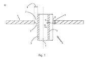
- FIG. 1a shows a perforated plate 1 having an opening 2, wherein in the opening 2, a tube 3 is inserted.
- the tube 3 is thus arranged in the longitudinal direction 4 with a longitudinal section 5 within the opening 2, so that between a Outer jacket surface 6 of the longitudinal section 5 and an inner circumferential surface 7 of the opening 2, a soldering gap 8 is formed.
- Due to the heat supply by the soldering process is according to FIG. 1b the wall 9 of the tube 3 in the radial direction 10 extends outwardly, wherein the inner circumferential surface 7 of the perforated plate 1 is expanded inwardly with respect to the radial direction 10 of the tube 3.
- the resulting solder gap 8 is significantly reduced and a solder not shown in detail can flow into it and connect the inner circumferential surface 7 of the opening 2 with the outer circumferential surface 6 of the tube 3.
- FIG. 2 shows an embodiment according to the invention, in which the inner circumferential surface 7 of the opening 2 is flattened in each case at different angles, wherein the tube 3 is itself abtuls at its end 11.
- Figure 3a and c show a slat plate 12 according to the invention, an upper shell 13 and a lower shell 14.
- lamella plate 12 has a corresponding waveform and is used in the longitudinal direction 15 between the upper shell 13 and lower shell 14.
- the upper shell 13 and lower shell 14 themselves are in FIGS. 3b and c shown, which in turn have characteristics 16, which are oriented away from the interior with composite upper shell 13 and lower shell 14.
- cartridge 17 allows a corresponding distance of the individual solid shells 18 with each other and to an inner circumferential surface of the cassette 17.
- the cassette 17 in turn, in FIG. 4 shown, corresponding indentations 19, which accomplish a distance to the inner circumferential surface 7 of the cartridge 17.
- corresponding indentations 19 which accomplish a distance to the inner circumferential surface 7 of the cartridge 17.
- the upper shell 13 and the lower shell 14 are soldered to one another on their longitudinal sides 22 and in particular are soldered to each other in a fluid-tight manner.
- thermo-mechanical stability is increased, as in the performance of the heat exchanger expansions analogous to the soldering lead to the fact that the plate heat exchanger 21 does not expand counterproductive to the solder joints produced and cracking occurs.
- the heat exchanger thus achieves a two to fourfold increase in service life.
- the individual parts can be positionally fixed to one another by means of resistance welding.
Abstract
Description
Die vorliegende Erfindung betrifft ein Verfahren zur Herstellung eines Wärmetauschers für ein Kraftfahrzeug gemäß den Merkmalen im Patentanspruch 1.The present invention relates to a method for producing a heat exchanger for a motor vehicle according to the features in claim 1.
Die vorliegende Erfindung betrifft weiterhin ein Verfahren zur Herstellung eines Plattenwärmetauschers für ein Kraftfahrzeug gemäß den Merkmalen im Patentanspruch 10.The present invention further relates to a method for producing a plate heat exchanger for a motor vehicle according to the features in
Aus dem Stand der Technik ist es bekannt, dass in Kraftfahrzeugen zur Wärmeübertragung Wärmetauscher eingesetzt werden. Beispielsweise werden solche Wärmetauscher als Kühler eingesetzt, um das Kühlwasser eines Kühlwasserkreislaufs einer Verbrennungskraftmaschine zu kühlen. Jedoch ist es auch bekannt, Gaswärmetauscher einzusetzen, mit deren Hilfe ein durch die Verbrennungskraftmaschine erzeugtes Abgas gekühlt wird. Zumeist werden dazu zwei verschiedene Medien durch den Wärmetauscher geleitet, wobei dann innerhalb des Wärmetauschers ein Wärmeübergang von einem Medium auf das andere erfolgt.From the prior art it is known that heat exchangers are used in motor vehicles for heat transfer. For example, such heat exchangers are used as coolers to cool the cooling water of a cooling water circuit of an internal combustion engine. However, it is also known to use gas heat exchangers, with the aid of which an exhaust gas generated by the internal combustion engine is cooled. In most cases they will passed two different media through the heat exchanger, wherein then takes place within the heat exchanger, a heat transfer from one medium to the other.
Zur konstruktiven Ausgestaltung eines Wärmetauschers sind verschiedenste Bauarten bekannt. So gibt es Plattenwärmetauscher oder aber auch Rohrbündelwärmetauscher. Letzterenfalls werden mehrere Wärmetauscherrohre innerhalb einer Wärmetauscherkassette angeordnet und über einen Rohrbund, der zumeist auch als Lochblech ausgebildet ist, formschlüssig und insbesondere fluiddicht gekoppelt. Durch die Wärmetauscherrohre strömt somit dann ein erstes Medium, wobei ein zweites Medium die Wärmetauscherrohre selbst umströmt.For structural design of a heat exchanger various types are known. So there are plate heat exchangers or even tube bundle heat exchangers. The latter case, a plurality of heat exchanger tubes are arranged within a heat exchanger cassette and coupled via a pipe collar, which is usually also designed as a perforated plate, positively and in particular fluid-tight manner. A first medium thus flows through the heat exchanger tubes, with a second medium flowing around the heat exchanger tubes themselves.
Zur Herstellung solcher Rohrbündelwärmetauscher werden die Wärmetauscherrohre in das Lochblech eingesetzt und in diesem formschlüssig und/oder stoffschlüssig lagefixiert. Im Falle einer formschlüssigen Lagefixierung wird das Rohr zumindest abschnittsweise in das Lochblech eingeführt und aufgeweitet bzw. aufgetulpt. Im Falle einer stoffschlüssigen Lagefixierung wird das Rohr entweder in dem Lochblech verlötet, verklebt oder aber auch verschweißt.To produce such tube bundle heat exchangers, the heat exchanger tubes are inserted into the perforated plate and fixed in position in this form-fitting and / or cohesive. In the case of a positive positional fixing, the tube is at least partially introduced into the perforated plate and expanded or aufgegetulpt. In the case of a cohesive position fixing the tube is either soldered in the perforated plate, glued or welded.
In dem Übergang zwischen Wärmetauscherrohr und Lochblech treten in der Praxis häufig, insbesondere bei langjähriger und intensiver Nutzung oder aber auch bei Durchströmung mit hochkorrosiven Medien Leckagen auf, so dass bei der Herstellung von aus dem Stand der Technik bekannten Wärmetauschern hohe Produktionskosten zur Herstellung der Verbindung zwischen Wärmetauscherrohr und Lochblech aufgrund eines erhöhten Fertigungsaufwands oder besonderen Materialeinsatzes entstehen.In the transition between the heat exchanger tube and perforated plate occur in practice frequently, especially for many years and intensive use or even in flow with highly corrosive media leaks, so that in the production of known from the prior art heat exchangers high production costs for the preparation of the connection between Heat exchanger tube and perforated plate due to an increased production effort or special material use arise.
Aufgabe der vorliegenden Erfindung ist es daher, ausgehend vom Stand der Technik, ein Verfahren aufzuzeigen, mit dem es möglich ist, einen Rohrwärmetauscher einfach und kostengünstig herzustellen, bei gleichzeitig hoher Dichtigkeit im Kopplungsbereich zwischen Wärmetauscherrohr und Lochblech sowie der Erhöhung der thermomechanischen Festigkeit und Schwingfestigkeit.It is therefore an object of the present invention, starting from the state of the art, to provide a method with which it is possible to produce a tube heat exchanger in a simple and cost-effective manner while at the same time achieving high density in the coupling region between heat exchanger tube and perforated plate and increasing the thermo-mechanical strength and fatigue strength.
Die zuvor genannte Aufgabe wird erfindungsgemäß mit den Merkmalen des Verfahrens zur Herstellung eines Wärmetauschers für ein Kraftfahrzeug im Patentanspruch 1 gelöst.The aforementioned object is achieved with the features of the method for producing a heat exchanger for a motor vehicle in claim 1.
Die zuvor genannte Aufgabe wird weiterhin mit einem Verfahren zur Herstellung eines Plattenwärmetauschers gemäß den Merkmalen im Patentanspruch 10 gelöst.The above object is further achieved by a method for producing a plate heat exchanger according to the features in
Vorteilhafte Ausgestaltungsvarianten des erfindungsgemäßen Verfahrens sind in den abhängigen Ansprüchen beschrieben.Advantageous embodiments of the method according to the invention are described in the dependent claims.
Das erfindungsgemäße Verfahren zur Herstellung eines Wärmetauschers für ein Kraftfahrzeug zeichnet sich durch folgende Verfahrensschritte aus:
- Bereitstellen eines Rohrs und eines Lochbleches, wobei das Rohr aus einem austenitischen Stahl ausgebildet ist und das Lochblech aus einem ferritischen Stahl ausgebildet ist,
- Zumindest abschnittsweises Einführen des Rohres in eine Öffnung des Lochbleches,
- Verlöten des Abschnittes des Rohres, der sich in der Öffnung befindet, mit der Innenmantelfläche der Öffnung, wobei sich das Rohr stärker ausdehnt als die Innenmantelfläche der Öffnung.
- Providing a tube and a perforated plate, wherein the tube is formed from an austenitic steel and the perforated plate is formed from a ferritic steel,
- At least partially insertion of the tube into an opening of the perforated plate,
- Soldering the portion of the tube, which is located in the opening, with the inner circumferential surface of the opening, wherein the tube expands more than the inner lateral surface of the opening.
Der erfindungsgemäße Ansatz sieht vor, dass zwei Werkstoffe, die mit Hinblick auf die Verwendung in einem Wärmetauscher gute Wärmeleitfähigkeiten besitzen sowie eine hohe Resistenz gegen Korrosion und ebenfalls eine hohe Langlebigkeit besitzen zur Herstellung des erfindungsgemäßen Wärmetauschers einzusetzen. Ebenfalls sind die Werkstoffe untereinander thermisch gut miteinander fügbar. Die Werkstoffe werden jedoch derart ausgewählt, dass der Werkstoff des Rohrs einen höheren Wärmeausdehnungskoeffizient besitzt, als der Werkstoff des Lochblechs. Das Rohr wird somit zumindest abschnittsweise in eine Öffnung des Lochblechs eingeführt und lagefixiert. Die Lagefixierung kann beispielsweise durch ein umformtechnisches Bearbeiten des Rohrs, insbesondere durch ein Aufweiten, Expandieren oder aber Auftulpen erfolgen, sie kann jedoch auch beispielsweise durch eine Hilfsvorrichtung, beispielsweise eine Lötstütze. Das Rohr und das Lochblech können jedoch auch durch eine Hilfsvorrichtung, beispielsweise eine Stütze während des thermischen Fügevorgangs zueinander lagefixiert werden.The approach according to the invention provides that two materials which have good heat conductivities with regard to use in a heat exchanger and also have a high resistance to corrosion and also a high longevity have to be used for producing the heat exchanger according to the invention. Also, the materials are mutually thermally good together. However, the materials are selected such that the material of the tube has a higher thermal expansion coefficient than the material of the perforated plate. The tube is thus at least partially inserted into an opening of the perforated plate and fixed in position. The position fixation can be done for example by a forming process of the tube, in particular by a widening, expanding or Auftulpen, but it can also, for example, by an auxiliary device, such as a solder support. However, the tube and the perforated plate can also be fixed in position relative to each other by an auxiliary device, for example a support during the thermal joining operation.
Im Anschluss an das Zusammensetzen von Rohr und Lochblech wird das Rohr mit dem Lochblech verlötet. Beispielsweise kann die gesamte Anordnung in einen Lötofen verbracht werden und miteinander verlötet werden. Durch die Erwärmung während des Lötvorgangs dehnt sich das Rohr stärker aus als die Innenmantelfläche der Öffnung. Hierdurch wird ein entstehender Lotspalt zwischen der Außenmantelfläche des Rohrs mit der Innenmantelfläche der Öffnung des Lochblechs minimiert, was sich positiv auf die Güte der hergestellten Lötverbindung auswirkt.Following the assembly of tube and perforated plate, the tube is soldered to the perforated plate. For example, the entire assembly can be placed in a soldering oven and soldered together. Due to the heating during the soldering process, the tube expands more than the inner surface of the opening. As a result, an emerging Lotspalt between the outer surface of the tube is minimized with the inner surface of the opening of the perforated plate, which has a positive effect on the quality of the solder joint produced.
Damit der erfindungsgemäße Effekt erzielt wird, wird das Rohr aus einer austenitischen Stahllegierung ausgebildet und das Lochblech aus einer ferritischen Stahllegierung. Gegebenenfalls weitere Legierungsbestandteile in den beiden oben genannten Legierungen sind im Rahmen der Erfindung inbegriffen. Als besonderer Vorteil stellt sich heraus, dass die Fertigungstoleranzen zur Herstellung des Lochblechs und des Rohrs größer sein können, als bei konventionell bekannten Lötprozessen. Diese wird jedoch durch den Lötprozess und die sich aufgrund der unterschiedlichen Wärmeausdehnungskoeffizienten einstellende Verringerung des Lotspalts ausgeglichen, ohne dass die damit hergestellte Lotverbindung in ihrer Qualität beeinflusst wird. Im Gegenteil, diese wird sogar aufgrund der verschiedenen Wärmeausdehnungskoeffizienten und dem minimierten Lotspalt in ihrer Qualität gesteigert.In order to achieve the effect according to the invention, the tube is formed from an austenitic steel alloy and the perforated plate from a ferritic steel alloy. Optionally further alloying constituents in the two abovementioned alloys are included within the scope of the invention. As a particular advantage turns out that the manufacturing tolerances for the production of the perforated plate and the tube can be larger than in conventionally known soldering processes. However, this is compensated by the soldering process and the resulting due to the different thermal expansion coefficient reduction of the Lotspalts, without the solder joint thus produced is affected in their quality. On the contrary, this is even increased due to the different thermal expansion coefficient and the minimized Lotspalt in their quality.
Insbesondere wird zwischen einer Außenmantelfläche des Rohrs, bevorzugt eines Abschnitts des Rohrs, der in einer Innenmantelfläche der Öffnung formschlüssig zur Anlage kommt, eine Übergangspassung oder eine Spielpassung ausgebildet. Hierdurch ist es möglich, zunächst die beiden Bauteile ineinander zu setzen. Zwar verbleibt zwischen den beiden Bauteilen zunächst ein hinreichender Lotspalt, so dass ein Lotzusatzwerkstoff und/oder ein Flussmittel in den Spalt fließen kann oder aber in dem sich einstellenden Lotspalt eingeschlossen ist. Durch den eigentlichen Lötvorgang selber dehnt sich dann das Rohr stärker aus als die Innenmantelfläche der Öffnung des Lochblechs, so dass der Lotspalt minimiert wird, was die Güte der damit hergestellten Lotverbindung erhöht.In particular, a transition fit or a clearance fit is formed between an outer circumferential surface of the tube, preferably a portion of the tube, which comes into positive engagement with an inner lateral surface of the opening. This makes it possible to first set the two components together. Although a sufficient solder gap initially remains between the two components, so that a solder additive material and / or a flux can flow into the gap or else be enclosed in the solder gap that occurs. By the actual soldering itself, the tube then expands more than the inner surface the opening of the perforated plate, so that the Lotspalt is minimized, which increases the quality of the solder joint produced therewith.
Hierzu wird dann während des Lötvorgangs selber der Spalt zwischen der Außenmantelfläche des Rohrs und der Innenmantelfläche der Öffnung auf eine Spielpassung oder Übermaßpassung geschrumpft.For this purpose, the gap between the outer circumferential surface of the tube and the inner lateral surface of the opening is then shrunk to a clearance fit or interference fit during the soldering process itself.
Der Lötvorgang selber wird dann bei einer Temperatur zwischen 300° und 800° C durchgeführt oder aber als Hochtemperaturlötvorgang mit Temperaturen von mehr als 800°, insbesondere mehr als 900° C, wobei insbesondere ein Lotflussmittel und/oder ein Zusatzwerkstoff verwendet wird. Der Lötvorgang selber kann dabei als Hartlötvorgang oder aber auch als Hochtemperaturlötvorgang durchgeführt werden. Im Rahmen der Erfindung wird insbesondere die gesamte Apparatur, mithin die zusammengesetzten Bauteile in einen Lötofen verbracht. Auch ist ein Induktionslötprozess mit der Hilfe von geeigneten Induktionsmitteln vorstellbar. Im Rahmen der Erfindung wird insbesondere ein Hochtemperaturlöten oder ein Hartlöten durchgeführt. Die Lötverfahren werden insbesondere als Vakuumverfahren, mithin als Vakuumlöten durchgeführt. Ebenfalls ist ein Löten unter Schutzgas vorstellbar, wobei hier insbesondere H2 oder aber H2/N2 als Schutzgasatmosphäre gewählt wird. Bevorzugt wird kein Flussmittel im Rahmen der Erfindung verwendet. Als Lotpaste selbst wird insbesondere ein Nickelbasislot oder aber auch ein Eisenbasislot, hier insbesondere ein Edelstahlbasislot verwendet.The soldering process itself is then carried out at a temperature between 300 ° and 800 ° C or as Hochtemperaturlötvorgang with temperatures of more than 800 °, in particular more than 900 ° C, in particular a Lotflussmittel and / or a filler material is used. The soldering process itself can be carried out as a brazing process or as a high-temperature brazing process. In the context of the invention, in particular the entire apparatus, thus the composite components are spent in a soldering oven. Also an induction soldering process with the help of suitable induction means is conceivable. In the context of the invention, in particular, a high-temperature soldering or brazing is performed. The soldering methods are carried out in particular as a vacuum method, and thus as a vacuum soldering. Also, brazing under protective gas is conceivable, in which case in particular H2 or H2 / N2 is selected as protective gas atmosphere. Preferably, no flux is used in the invention. As a solder paste itself is in particular a nickel-based solder or even a Eisenbasislot, in particular a Edelstahlbasislot used.
Für das Lochblech wird insbesondere ein ferritischer Chromstahl verwendet, der gegebenenfalls andere Gefügebestandteile aufweisen kann. Insbesondere wird ein Werkstoff aus der nachfolgenden Gruppe verwendet: 1.4016, 1.4509, 1.4510, 1.4521.For the perforated plate in particular a ferritic chrome steel is used, which may optionally have other structural constituents. In particular, a material from the following group is used: 1.4016, 1.4509, 1.4510, 1.4521.
Für das Rohr selber bzw. das Wärmetauscherrohr wird ein austenitischer rostfreier Stahl verwendet, der gegebenenfalls weitere Gefügebestandteile aufweisen kann. Im Rahmen der Erfindung wird insbesondere ein Stahl verwendet, der aus der nachfolgend aufgezählten Gruppe ausgewählt ist: 1.4301, 1.4307, 1.4401, 1.4306.For the tube itself or the heat exchanger tube, an austenitic stainless steel is used, which may optionally have further structural components. In the context of the invention, in particular a steel is used, which is selected from the group enumerated below: 1.4301, 1.4307, 1.4401, 1.4306.
Im Rahmen der Erfindung ist das Rohr bzw. das Wärmetauscherrohr besonders bevorzugt als Beulenrohr oder aber auch als Wellrohr oder Drallrohr ausgebildet. Hierdurch wird in dem Rohr selbst eine Turbulenz erzeugt, die die Wärmetauscherleistung erhöht, wobei der Gegendruck innerhalb des Rohrs selbst in Bezug auf die Erhöhung der Wärmetauscherleistung zu vernachlässigen ist.In the context of the invention, the tube or the heat exchanger tube is particularly preferably designed as a bulge tube or else as a corrugated tube or swirl tube. As a result, a turbulence is generated in the pipe itself, which increases the heat exchanger performance, wherein the back pressure within the pipe itself is negligible in relation to the increase of the heat exchanger performance.
Insbesondere wird der Wärmetauscher als Rohrbündelwärmetauscher hergestellt, wobei mehrere Rohre an mindestens einem Lochblech verlötet werden und die Rohre mit dem Lochblech in einem Außenblech oder einer Kassette angeordnet werden. Die Kassette selbst weist dann wiederum Anschlüsse auf, um hier Fluidleitungen der durch den Wärmetauscher zu führenden Fluide anzuschließen.In particular, the heat exchanger is produced as a tube bundle heat exchanger, wherein a plurality of tubes are soldered to at least one perforated plate and the tubes are arranged with the perforated plate in an outer plate or a cassette. The cassette itself then has connections in order to connect fluid lines of the fluids to be passed through the heat exchanger.
Insbesondere wird der Werkstoff des Lochblechs in Relation zu dem Werkstoff des Rohrs derart ausgewählt, dass deren Wärmeausdehnungskoeffizient sich im Verhältnis von 1 : 1,2 bis 2, insbesondere von 1 : 1,4 bis 1,6 und ganz besonders bevorzugt von 1 : 1,5 unterscheiden.In particular, the material of the perforated plate is selected in relation to the material of the tube such that its coefficient of thermal expansion is in the ratio of 1: 1.2 to 2, in particular from 1: 1.4 to 1.6 and most preferably from 1: 1 , 5 different.
Das erfindungsgemäße Verfahren macht es ebenfalls möglich, dass das Rohr und das Lochblech nicht nur stoffschlüssig, sondern ergänzt auch formschlüssig miteinander gefügt werden. Hierzu wird insbesondere das Lochblech einseitig durch das Rohr durchgriffen und aufgetulpt oder aber aufgeweitet und anschließend verlötet.The method according to the invention also makes it possible for the tube and the perforated plate not only to be joined in a material-locking manner but also in a form-fitting manner. For this purpose, in particular, the perforated plate is unilaterally penetrated through the tube and aufgetulpt or expanded and then soldered.
Im Rahmen der Erfindung betragen die thermischen Ausdehnungskoeffizienten im Mittel bei ferritischen Stählen circa 12 x 1061/K und bei austenitischen Stählen circa 17 x 1061/K. Hierdurch wird bei um circa 30 % erhöhten Toleranzen, mithin einer stärkeren Abweichung der Sollmaße von Rohr und Lochblech, eine gleiche Festigkeit der hergestellten Lötverbindung erreicht. Alternativ dazu wird bei gleichbleibenden Toleranzen eine Steigerung der Festigkeit der hergestellten Verbindung erreicht. Bei eingesetzten Nickelloten bilden sich bei großen Spalten intermetallische Phasen aus, die die Schwingfestigkeit der hergestellten Lotverbindung reduzieren. Bei eingesetzten Kupferloten bilden sich bei großen Spalten insbesondere die natürlichen Eigenschaften des Reinkupfers aus, mithin wird eine sehr duktile Lotverbindung mit niedriger für Kupfer spezifischer Festigkeit bereitgestellt.In the context of the invention, the thermal expansion coefficients on average for ferritic steels are approximately 12 × 10 6 1 / K and for austenitic steels approximately 17 × 10 6 1 / K. As a result, at about 30% increased tolerances, thus a greater deviation of the nominal dimensions of the tube and perforated plate, an equal strength of the produced solder joint is achieved. Alternatively, with constant tolerances, an increase in the strength of the connection produced is achieved. When nickel ions are used, intermetallic phases develop in the case of large gaps, which reduce the fatigue strength of the solder joint produced. With copper solders used, in particular the natural properties of the pure copper are formed in the case of large gaps, thus providing a very ductile solder joint with low copper-specific strength.
Die vorliegende Erfindung sieht hier vor, austenitische Stähle mit einem kubisch flächenzentrierten Kristallgitter für das Rohr einzusetzen, wobei die austenitischen Stähle unter anderem die Legierungsbestandteile Chrom und Nickel aufweisen. Für die ferritischen Stähle ist ein kubisch raumzentriertes Kristallgitter ausgebildet, wobei die ferritischen Stähle maßgeblich für das Lochblech eingesetzt werden. Die ferritischen Stähle selber sind maßgeblich mit Chrom legiert und weisen einen zu vernachlässigenden oder aber keinen Anteil des kostenintensiven Legierungselements Nickel auf.The present invention provides here austenitic steels with a cubic face-centered crystal lattice for the pipe to use, wherein the austenitic Steels have among others the alloying components chromium and nickel. For the ferritic steels, a cubic body-centered crystal lattice is formed, the ferritic steels being used significantly for the perforated plate. The ferritic steels themselves are significantly alloyed with chromium and have a negligible or no share of the cost-intensive alloying element nickel.
Das kubisch flächenzentrierte Kristallgitter der austenitischen Stähle weist eine hohe Dauerfestigkeit auf für einen Temperaturbereich von circa 0,4 mal der Schmelztemperatur des Werkstoffs. Somit ist das Lochblech aus einem austenitischen Stahl ausgebildet und wird in der Regel von circa 300° bis 600° C heißem Abgas umströmt. Bei Volllast der Verbrennungskraftmaschine kann das Abgas temporär auch eine höherere Temperatur aufweisen. Die austenitischen Rohre des Wärmetauschers sind jedoch direkt im Kühlmedium, maßgeblich im Kühlwasser des Wärmetauschers eingebettet bzw. von diesem umströmt, wobei die durchschnittliche Temperatur des Kühlmediums bei 50° bis 90° C, insbesondere bei 60° bis 70° C liegt. Dies ist deutlich unter einem Temperaturniveau von 0,4 mal der Schmelztemperatur des Werkstoffs. Somit ist es möglich, dass das Lochblech mit einer größeren Fläche, die der Abgastemperatur ausgesetzt ist, als austenitisches Bauteil auszubilden, welches robust aber auch kostenintensiv ist, wobei die Rohre als ferritisches Bauteil ausgebildet werden können, die eine deutliche Kostenersparnis zu einem austenitischen Stahl darstellt, gleichsam jedoch die geforderte Festigkeit an den Wärmetauscher erfüllt.The cubic face-centered crystal lattice of the austenitic steels has a high fatigue strength for a temperature range of approximately 0.4 times the melting temperature of the material. Thus, the perforated plate is formed of an austenitic steel and is flowed around from about 300 ° to 600 ° C hot exhaust gas usually. At full load of the internal combustion engine, the exhaust gas may temporarily have a higher temperature. However, the austenitic tubes of the heat exchanger are embedded directly in the cooling medium, significantly in the cooling water of the heat exchanger or flows around it, wherein the average temperature of the cooling medium at 50 ° to 90 ° C, in particular at 60 ° to 70 ° C. This is clearly below a temperature level of 0.4 times the melting temperature of the material. Thus, it is possible that the perforated plate having a larger area, which is exposed to the exhaust gas temperature, austenitic component, which is robust but also costly, wherein the tubes can be formed as a ferritic component, which represents a significant cost savings to an austenitic steel , but as it meets the required strength to the heat exchanger.
Die vorliegende Erfindung betrifft weiterhin ein Verfahren zur Herstellung eines Plattenwärmetauschers für ein Kraftfahrzeug, gekennzeichnet durch folgende Verfahrensschritte:
- Bereitstellen mindestens eines Lamellenbleches sowie zweier Halbschalen, welche eine Oberschale und eine Unterschale sind,
- Aufbringen eines Lotes auf das Lamellenblech und auf die Oberschale und/oder die Unterschale,
- Einsetzen des Lamellenblechs in die Oberschale oder Unterschale und Zusammensetzen von Oberschale und Unterschale zu einer Vollschale,
- Einsetzen der Vollschale in eine Kassette und Verlöten der Anordnung,
- wobei das Lamellenblech und die Kassette aus einem austenitischen Werkstoff ausgebildet sind und die Halbschalen aus einem ferritischen Werkstoff und die Kassette nach innen gerichtete Einprägungen aufweist.
- Providing at least one lamination plate and two half shells, which are an upper shell and a lower shell,
- Applying a solder to the lamination plate and to the upper shell and / or the lower shell,
- Inserting the lamellar plate into the upper shell or lower shell and assembling the upper shell and lower shell into a solid shell,
- Insert the full tray into a cassette and solder the assembly,
- wherein the lamination plate and the cassette are formed of an austenitic material and the half shells made of a ferritic material and the cassette has inwardly directed indentations.
Somit wird zunächst bei dem erfindungsgemäßen Herstellungsverfahren für den Plattenwärmetauscher das Lamellenblech sowie mindestens die Oberschale oder aber Unterschale mit einem Lotwerkstoff versehen. Das Lamellenblech wird dann in die Oberschale oder aber Unterschale eingesetzt und mit der dazu korrespondierenden Schale derart verschlossen, dass eine Vollschale entsteht, die das Lamellenblech umfangsseitig umgreift. Die Vollschale weist dann an einer Eintritts- und einer Austrittsseite eine Öffnung auf, so dass ein Medium durch die Vollschale geleitet werden kann, wobei innerhalb der Vollschale das Lamellenblech für eine entsprechende Turbulenzerzeugung sowie einen erhöhten Wärmeübergang des durch die Vollschale strömenden Mediums sorgt. Die Unterschale und die Oberschale werden entlang ihrer Längsseiten insbesondere mit dem Lötvorgang fluiddicht miteinander gekoppelt.Thus, first, in the inventive manufacturing method for the plate heat exchanger, the lamella plate and at least the upper shell or lower shell provided with a solder material. The lamella plate is then inserted into the upper shell or lower shell and closed with the corresponding shell so that a full shell is formed, which surrounds the lamellae circumferentially. The solid shell then has an opening at an inlet and an outlet side, so that a medium can be passed through the solid shell, wherein inside the solid shell the lamella plate ensures a corresponding turbulence generation and an increased heat transfer of the medium flowing through the solid shell. The lower shell and the upper shell are fluid-tightly coupled together along their longitudinal sides, in particular with the soldering process.
Erfindungsgemäß ist weiterhin vorgesehen, dass durch die stärkere Ausdehnung des Lamellenbleches, aber auch der in der Kassette befindlichen nach innen gerichteten Einprägungen, gegenüber der Oberschale und der Unterschale eine Lötverbindung mit besonders hoher Qualität und Dichtigkeit hergestellt wird.According to the invention, it is further provided that the soldered connection with particularly high quality and tightness is produced by the greater extent of the lamination plate, but also by the inwardly directed impressions located in the cassette, in relation to the upper shell and the lower shell.
Während des auf den Lotvorgang folgenden Abkühlens schrumpfen die Bauteile wiederum annähernd in ihren Ursprungszustand zurück. Hierdurch entsteht ein innerer Spannungsvorgang, so dass der Wärmetauscher zunächst nach der eigentlichen Herstellung und vor seinem Verbau bzw. Einsatz in dem Kraftfahrzeug besonders qualitativ hochwertigen Lötverbindungen unterzogen wird. Während des Einsatzes im Kraftfahrzeug ist der Kraftfahrzeugwärmetauscher jedoch dann Einsatzbedingungen aufgrund der durch ihn zu führenden Medien von bis zu mehreren 100°C ausgesetzt. Hierdurch entsteht während des Einsatzes eine derartige Wärmebehandlung, die die Eigenspannungen abbaut, so dass bereits nach einem Betrieb des Kraftfahrzeugwärmetauschers von 2 bis 5 Stunden die Eigenspannungen nahezu vollständig und dauerhaft abgebaut sind. Mithin steht der erfindungsgemäß hergestellte Kraftfahrzeugwärmetauscher in Rohrversion, aber auch in Plattenversion dann bei Raumtemperatur nicht mehr unter Eigenspannung. Im Betriebszustand dehnen sich wiederum die austenitischen Werkstoffe stärker aus gegenüber den ferritischen Werkstoffen, was die thermomechanische Stabilität eines solch hergestellten Kraftfahrzeugwärmetauschers erhöht und gegenüber herkömmlichen verlöteten Kraftfahrzeugwärmetauschern, welche insbesondere aus gleichartigen Werkstoffen ausgebildet sind, eine Erhöhung der Lebensdauer in Bezug auf die Standfestigkeit erreichen. Alle weiteren zuvor genannten Verfahrensmerkmale für den Rohrwärmetauscher sind für den Plattenwärmetauscher analog anwendbar.During the cooling process following the soldering process, the components in turn shrink back approximately to their original state. This creates an internal stress process, so that the heat exchanger is first subjected to high-quality solder joints after the actual production and before its installation or use in the motor vehicle. During use in the motor vehicle, however, the vehicle heat exchanger is then exposed to operating conditions due to the media to be led through it up to several 100 ° C. This creates during use a Such heat treatment, which reduces the residual stresses, so that even after operation of the motor vehicle heat exchanger from 2 to 5 hours, the residual stresses are almost completely and permanently reduced. Consequently, the automotive heat exchanger according to the invention produced in tube version, but also in plate version is then no longer under residual stress at room temperature. In operation, in turn, the austenitic materials expand more than the ferritic materials, which increases the thermo-mechanical stability of such a manufactured automotive heat exchanger and compared to conventional soldered automotive heat exchangers, which are in particular made of similar materials, increase the life in terms of stability. All other aforementioned process features for the tube heat exchanger are analogously applicable for the plate heat exchanger.
Weitere Vorteile, Merkmale, Eigenschaften und Aspekte der vorliegenden Erfindung werden in der nachfolgenden Beschreibung erläutert. Bevorzugte Ausführungsvarianten werden in den schematischen Figuren dargestellt. Diese dienen dem einfachen Verständnis der Erfindung. Es zeigen:
- Figur 1a, b
- die Anordnung von einem Rohr in einem Lochblech vor und während dem Lötvorgang,
Figur 2- ein aufgetulptes Rohr in einem Lochblech,
- Figur 3a bis c
- ein erfindungsgemäßes Lamellenblech sowie eine Oberschale und Unterschale und
- Figur 4
- einen erfindungsgemäß hergestellten Plattenwärmetauscher.
- FIG. 1a, b
- the arrangement of a tube in a perforated plate before and during the soldering process,
- FIG. 2
- a sculpted pipe in a perforated sheet,
- Figure 3a to c
- an inventive slat plate and an upper shell and lower shell and
- FIG. 4
- a plate heat exchanger produced according to the invention.
In den Figuren werden für gleiche oder ähnliche Bauteile dieselben Bezugszeichen verwendet, auch wenn eine wiederholte Beschreibung aus Vereinfachungsgründen entfällt.In the figures, the same reference numerals are used for the same or similar components, even if a repeated description is omitted for reasons of simplicity.
![]()
![]()
Die Kassette 17 weist wiederum, in
Auch wird gerade die thermomechanische Stabilität erhöht, da im Betriebsverhalten des Wärmetauschers Ausdehnungen analog zu dem Lötverfahren dazu führen, dass der Plattenwärmetauscher 21 sich nicht kontraproduktiv zu den hergestellten Lötverbindungen ausdehnt und Rissbildungen entstehen. Der Wärmetauscher erreicht so eine zwei- bis vierfache Lebensdauererhöhung. Auch können die einzelnen Teile mittels Widerstandsschweißen punktuell zueinander lagefixiert werden.Also, just the thermo-mechanical stability is increased, as in the performance of the heat exchanger expansions analogous to the soldering lead to the fact that the
- 1 - Lochblech1 - perforated plate
- 2 - Öffnung2 - opening
- 3 - Rohr3 - pipe
- 4 - Längsrichtung zu 34 - longitudinal direction to 3
- 5 - Längenabschnitt5 - length section
- 6 - Außenmantelfläche6 - outer circumferential surface
- 7 - Innenmantefläche7 - inner edge surface
- 8 - Lotspalt8 - Lotspalt
- 9 - Wandung zu 39 - wall to 3
- 10- Radialrichtung zu 310- radial direction to 3
- 11 - Ende zu 311 - end to 3
- 12 - Lamellenblech12 - slat plate
- 13 - Oberschale13 - Upper shell
- 14 - Unterschale14 - lower shell
- 15 - Längsrichtung15 - longitudinal direction
- 16 - Ausprägungen16 - characteristics
- 17 - Kassette17 - cassette
- 18 - Vollschale18 - full bowl
- 19 - Einprägungen19 - impressions
- 20 - Öffnungen20 - openings
- 21 - Plattenwärmetauscher21 - plate heat exchanger
- 22 - Längsseiten22 - long sides
-
- Wärmezufuhr
 - Heat supply
Claims (15)
Priority Applications (1)
| Application Number | Priority Date | Filing Date | Title |
|---|---|---|---|
| EP16160435.0A EP3054259B1 (en) | 2012-09-19 | 2013-09-10 | Method for manufacturing a heat exchanger |
Applications Claiming Priority (1)
| Application Number | Priority Date | Filing Date | Title |
|---|---|---|---|
| DE102012108821.7A DE102012108821B4 (en) | 2012-09-19 | 2012-09-19 | Method for producing a heat exchanger |
Related Child Applications (2)
| Application Number | Title | Priority Date | Filing Date |
|---|---|---|---|
| EP16160435.0A Division EP3054259B1 (en) | 2012-09-19 | 2013-09-10 | Method for manufacturing a heat exchanger |
| EP16160435.0A Division-Into EP3054259B1 (en) | 2012-09-19 | 2013-09-10 | Method for manufacturing a heat exchanger |
Publications (3)
| Publication Number | Publication Date |
|---|---|
| EP2711659A2 true EP2711659A2 (en) | 2014-03-26 |
| EP2711659A3 EP2711659A3 (en) | 2016-01-06 |
| EP2711659B1 EP2711659B1 (en) | 2017-11-08 |
Family
ID=49223538
Family Applications (2)
| Application Number | Title | Priority Date | Filing Date |
|---|---|---|---|
| EP13183635.5A Active EP2711659B1 (en) | 2012-09-19 | 2013-09-10 | Method for manufacturing a heat exchanger |
| EP16160435.0A Active EP3054259B1 (en) | 2012-09-19 | 2013-09-10 | Method for manufacturing a heat exchanger |
Family Applications After (1)
| Application Number | Title | Priority Date | Filing Date |
|---|---|---|---|
| EP16160435.0A Active EP3054259B1 (en) | 2012-09-19 | 2013-09-10 | Method for manufacturing a heat exchanger |
Country Status (2)
| Country | Link |
|---|---|
| EP (2) | EP2711659B1 (en) |
| DE (1) | DE102012108821B4 (en) |
Cited By (1)
| Publication number | Priority date | Publication date | Assignee | Title |
|---|---|---|---|---|
| DE102014106807A1 (en) * | 2014-05-14 | 2015-11-19 | Benteler Automobiltechnik Gmbh | Flue gas heat exchanger made of duplex steel |
Families Citing this family (2)
| Publication number | Priority date | Publication date | Assignee | Title |
|---|---|---|---|---|
| DE102016215265A1 (en) * | 2016-08-16 | 2018-02-22 | Mahle International Gmbh | Production method of a heat exchanger tube |
| JP2020085288A (en) * | 2018-11-20 | 2020-06-04 | 株式会社デンソー | Heat exchanger |
Family Cites Families (17)
| Publication number | Priority date | Publication date | Assignee | Title |
|---|---|---|---|---|
| DE890635C (en) * | 1953-08-13 | Rheinische Rohrenwerke Aktiengesellschaft, Mülheim/Ruhr | Process for the production of pipes from high-weight, in particular aluminum-Teftitic chromium-nickel steels | |
| CH474733A (en) * | 1966-05-13 | 1969-06-30 | Gen Electric | Heat exchanger |
| DE3149285C2 (en) * | 1981-12-12 | 1985-11-21 | MTU Motoren- und Turbinen-Union München GmbH, 8000 München | Method for connecting the tubes of a heat exchanger matrix to the heat exchanger base of a collecting tank |
| US4703885A (en) * | 1985-11-15 | 1987-11-03 | Ga Technologies Inc. | Method of welding austenitic steel to ferritic steel with filler alloys |
| DE3720597C1 (en) * | 1987-05-12 | 1988-08-11 | Schneider Gesenkschmiede | Hollow shaft |
| DE19821406A1 (en) * | 1998-05-13 | 1999-11-18 | Lurgi Zimmer Ag | Sealing element for melt channels |
| JP4540920B2 (en) * | 2002-02-18 | 2010-09-08 | 三菱レイヨン株式会社 | Vertical multitubular heat exchanger and distillation column system including the same |
| JP2005055153A (en) * | 2003-08-07 | 2005-03-03 | Toyota Motor Corp | Heat exchanger |
| CA2503424A1 (en) * | 2005-04-01 | 2006-10-01 | Dana Canada Corporation | Stacked-tube heat exchanger |
| US20060254761A1 (en) * | 2005-05-11 | 2006-11-16 | Denso Corporation | Brazed structure and method of manufacturing the same |
| DE102005030438A1 (en) * | 2005-06-30 | 2007-01-04 | Behr Gmbh & Co. Kg | Clamping device for soldering a multi-part metal unit of especially a heat exchanger is made of a material with lower thermal expansion coefficient and is placed round metal parts in soldering furnace |
| DE102005055481A1 (en) * | 2005-11-18 | 2007-05-24 | Behr Gmbh & Co. Kg | Heat exchanger for an internal combustion engine |
| US8915292B2 (en) * | 2006-02-07 | 2014-12-23 | Modine Manufacturing Company | Exhaust gas heat exchanger and method of operating the same |
| EP1982790B1 (en) * | 2007-04-20 | 2018-09-19 | Innospin AG | Heat exchanger pipe and method for manufacturing heat exchanger pipes |
| JP5320010B2 (en) * | 2008-10-07 | 2013-10-23 | 三菱重工業株式会社 | Welding structure of the nozzle head |
| JP4773541B2 (en) * | 2009-04-09 | 2011-09-14 | マルヤス工業株式会社 | Multi-tube heat exchanger |
| DE102010029287A1 (en) * | 2009-05-28 | 2011-01-05 | Behr Gmbh & Co. Kg | Layer heat exchanger for high temperatures |
-
2012
- 2012-09-19 DE DE102012108821.7A patent/DE102012108821B4/en not_active Revoked
-
2013
- 2013-09-10 EP EP13183635.5A patent/EP2711659B1/en active Active
- 2013-09-10 EP EP16160435.0A patent/EP3054259B1/en active Active
Non-Patent Citations (1)
| Title |
|---|
| None |
Cited By (3)
| Publication number | Priority date | Publication date | Assignee | Title |
|---|---|---|---|---|
| DE102014106807A1 (en) * | 2014-05-14 | 2015-11-19 | Benteler Automobiltechnik Gmbh | Flue gas heat exchanger made of duplex steel |
| EP2950031A1 (en) * | 2014-05-14 | 2015-12-02 | Benteler Automobiltechnik GmbH | Exhaust gas heat exchanger made from duplex steel |
| DE102014106807B4 (en) * | 2014-05-14 | 2017-12-21 | Benteler Automobiltechnik Gmbh | Flue gas heat exchanger made of duplex steel |
Also Published As
| Publication number | Publication date |
|---|---|
| EP3054259B1 (en) | 2017-11-08 |
| EP2711659A3 (en) | 2016-01-06 |
| EP2711659B1 (en) | 2017-11-08 |
| DE102012108821B4 (en) | 2014-08-14 |
| EP3054259A1 (en) | 2016-08-10 |
| DE102012108821A1 (en) | 2014-03-20 |
Similar Documents
| Publication | Publication Date | Title |
|---|---|---|
| EP1929231B1 (en) | Heat exchanger, in particular exhaust gas heat exchanger for motor vehicles | |
| EP2156916B1 (en) | Method of manufacturing steam producing tube walls composed mostly of martensitic steels containing 9-12% chromium | |
| EP1979699B1 (en) | Tube bundle heat exchanger | |
| EP1682767B1 (en) | Heat exchanger | |
| DE102017214427B4 (en) | Stator for an electrical machine, in particular a motor vehicle, and method for producing such a stator | |
| EP1995544A2 (en) | Heat exchanger, in particular charger air cooler or exhaust gas cooler for a combustion engine of a motor vehicle and manufacturing method therefor | |
| DE102007010134A1 (en) | Heat exchanger e.g. radiator, for e.g. exhaust gas recycling system of diesel engine, has block closure element for fluid-sealed separation of chamber and fluid contact, and housing provided for connecting block at contact | |
| DE102008002746A1 (en) | Heat exchanger for the exhaust system of a motor vehicle, method for producing a heat exchanger and assembly tool for this purpose | |
| DE102013100885A1 (en) | Heat exchanger with feed channel | |
| EP2711659B1 (en) | Method for manufacturing a heat exchanger | |
| DE112016003449T5 (en) | Heat exchanger and method for producing the same | |
| DE102011008119A1 (en) | Double pipe for double pipe heat exchanger for motor vehicle engine, has recesses and projections that are formed in outer pipe wall and inner pipe wall respectively and are radially inserted into annular gap | |
| EP2729679B1 (en) | Method for producing an exhaust gas system, and exhaust gas system | |
| DE102016207319A1 (en) | Heat exchanger and method for producing such a heat exchanger | |
| DE602004004155T2 (en) | HEAT EXCHANGER WITH IMPROVED TRENCH WALL | |
| EP3232149B1 (en) | Heat exchanger | |
| EP2950031B1 (en) | Exhaust gas heat exchanger made from duplex steel | |
| DE102015210942A1 (en) | Heat exchanger | |
| DE102012208558A1 (en) | Process for producing a cohesive connection | |
| EP3196579A1 (en) | Heat exchanger | |
| DE102021131552B3 (en) | Process for manufacturing a flat tube | |
| EP1769212B1 (en) | Heat exchanger, especially for motor vehicles | |
| DE102013109925A1 (en) | Exhaust gas heat exchanger | |
| EP1826522A2 (en) | Heat exchanger | |
| DE102004024831A1 (en) | Flange link establishing method for exhaust gas system of vehicle, involves inserting socket through opening of flange, and welding or soldering pipe and socket together in section of socket |
Legal Events
| Date | Code | Title | Description |
|---|---|---|---|
| PUAI | Public reference made under article 153(3) epc to a published international application that has entered the european phase |
Free format text: ORIGINAL CODE: 0009012 |
|
| AK | Designated contracting states |
Kind code of ref document: A2 Designated state(s): AL AT BE BG CH CY CZ DE DK EE ES FI FR GB GR HR HU IE IS IT LI LT LU LV MC MK MT NL NO PL PT RO RS SE SI SK SM TR |
|
| AX | Request for extension of the european patent |
Extension state: BA ME |
|
| RIC1 | Information provided on ipc code assigned before grant |
Ipc: B23K 1/00 20060101ALI20150724BHEP Ipc: F28F 9/18 20060101AFI20150724BHEP Ipc: F28F 21/08 20060101ALI20150724BHEP Ipc: F28D 7/16 20060101ALI20150724BHEP |
|
| PUAL | Search report despatched |
Free format text: ORIGINAL CODE: 0009013 |
|
| AK | Designated contracting states |
Kind code of ref document: A3 Designated state(s): AL AT BE BG CH CY CZ DE DK EE ES FI FR GB GR HR HU IE IS IT LI LT LU LV MC MK MT NL NO PL PT RO RS SE SI SK SM TR |
|
| AX | Request for extension of the european patent |
Extension state: BA ME |
|
| RIC1 | Information provided on ipc code assigned before grant |
Ipc: B23K 1/00 20060101ALI20151202BHEP Ipc: F28D 21/00 20060101ALI20151202BHEP Ipc: F28F 9/18 20060101AFI20151202BHEP Ipc: F28F 21/08 20060101ALI20151202BHEP Ipc: F28D 7/16 20060101ALI20151202BHEP Ipc: B23K 1/002 20060101ALI20151202BHEP |
|
| 17P | Request for examination filed |
Effective date: 20160315 |
|
| 17Q | First examination report despatched |
Effective date: 20160804 |
|
| GRAP | Despatch of communication of intention to grant a patent |
Free format text: ORIGINAL CODE: EPIDOSNIGR1 |
|
| INTG | Intention to grant announced |
Effective date: 20170516 |
|
| GRAS | Grant fee paid |
Free format text: ORIGINAL CODE: EPIDOSNIGR3 |
|
| GRAA | (expected) grant |
Free format text: ORIGINAL CODE: 0009210 |
|
| AK | Designated contracting states |
Kind code of ref document: B1 Designated state(s): AL AT BE BG CH CY CZ DE DK EE ES FI FR GB GR HR HU IE IS IT LI LT LU LV MC MK MT NL NO PL PT RO RS SE SI SK SM TR |
|
| REG | Reference to a national code |
Ref country code: GB Ref legal event code: FG4D Free format text: NOT ENGLISH |
|
| REG | Reference to a national code |
Ref country code: CH Ref legal event code: EP Ref country code: AT Ref legal event code: REF Ref document number: 944540 Country of ref document: AT Kind code of ref document: T Effective date: 20171115 |
|
| REG | Reference to a national code |
Ref country code: IE Ref legal event code: FG4D Free format text: LANGUAGE OF EP DOCUMENT: GERMAN |
|
| REG | Reference to a national code |
Ref country code: DE Ref legal event code: R096 Ref document number: 502013008754 Country of ref document: DE |
|
| REG | Reference to a national code |
Ref country code: NL Ref legal event code: MP Effective date: 20171108 |
|
| REG | Reference to a national code |
Ref country code: LT Ref legal event code: MG4D |
|
| PG25 | Lapsed in a contracting state [announced via postgrant information from national office to epo] |
Ref country code: FI Free format text: LAPSE BECAUSE OF FAILURE TO SUBMIT A TRANSLATION OF THE DESCRIPTION OR TO PAY THE FEE WITHIN THE PRESCRIBED TIME-LIMIT Effective date: 20171108 Ref country code: NL Free format text: LAPSE BECAUSE OF FAILURE TO SUBMIT A TRANSLATION OF THE DESCRIPTION OR TO PAY THE FEE WITHIN THE PRESCRIBED TIME-LIMIT Effective date: 20171108 Ref country code: NO Free format text: LAPSE BECAUSE OF FAILURE TO SUBMIT A TRANSLATION OF THE DESCRIPTION OR TO PAY THE FEE WITHIN THE PRESCRIBED TIME-LIMIT Effective date: 20180208 Ref country code: SE Free format text: LAPSE BECAUSE OF FAILURE TO SUBMIT A TRANSLATION OF THE DESCRIPTION OR TO PAY THE FEE WITHIN THE PRESCRIBED TIME-LIMIT Effective date: 20171108 Ref country code: LT Free format text: LAPSE BECAUSE OF FAILURE TO SUBMIT A TRANSLATION OF THE DESCRIPTION OR TO PAY THE FEE WITHIN THE PRESCRIBED TIME-LIMIT Effective date: 20171108 Ref country code: ES Free format text: LAPSE BECAUSE OF FAILURE TO SUBMIT A TRANSLATION OF THE DESCRIPTION OR TO PAY THE FEE WITHIN THE PRESCRIBED TIME-LIMIT Effective date: 20171108 |
|
| PG25 | Lapsed in a contracting state [announced via postgrant information from national office to epo] |
Ref country code: HR Free format text: LAPSE BECAUSE OF FAILURE TO SUBMIT A TRANSLATION OF THE DESCRIPTION OR TO PAY THE FEE WITHIN THE PRESCRIBED TIME-LIMIT Effective date: 20171108 Ref country code: GR Free format text: LAPSE BECAUSE OF FAILURE TO SUBMIT A TRANSLATION OF THE DESCRIPTION OR TO PAY THE FEE WITHIN THE PRESCRIBED TIME-LIMIT Effective date: 20180209 Ref country code: LV Free format text: LAPSE BECAUSE OF FAILURE TO SUBMIT A TRANSLATION OF THE DESCRIPTION OR TO PAY THE FEE WITHIN THE PRESCRIBED TIME-LIMIT Effective date: 20171108 Ref country code: IS Free format text: LAPSE BECAUSE OF FAILURE TO SUBMIT A TRANSLATION OF THE DESCRIPTION OR TO PAY THE FEE WITHIN THE PRESCRIBED TIME-LIMIT Effective date: 20180308 Ref country code: BG Free format text: LAPSE BECAUSE OF FAILURE TO SUBMIT A TRANSLATION OF THE DESCRIPTION OR TO PAY THE FEE WITHIN THE PRESCRIBED TIME-LIMIT Effective date: 20180208 Ref country code: RS Free format text: LAPSE BECAUSE OF FAILURE TO SUBMIT A TRANSLATION OF THE DESCRIPTION OR TO PAY THE FEE WITHIN THE PRESCRIBED TIME-LIMIT Effective date: 20171108 |
|
| PG25 | Lapsed in a contracting state [announced via postgrant information from national office to epo] |
Ref country code: EE Free format text: LAPSE BECAUSE OF FAILURE TO SUBMIT A TRANSLATION OF THE DESCRIPTION OR TO PAY THE FEE WITHIN THE PRESCRIBED TIME-LIMIT Effective date: 20171108 Ref country code: CY Free format text: LAPSE BECAUSE OF FAILURE TO SUBMIT A TRANSLATION OF THE DESCRIPTION OR TO PAY THE FEE WITHIN THE PRESCRIBED TIME-LIMIT Effective date: 20171108 Ref country code: DK Free format text: LAPSE BECAUSE OF FAILURE TO SUBMIT A TRANSLATION OF THE DESCRIPTION OR TO PAY THE FEE WITHIN THE PRESCRIBED TIME-LIMIT Effective date: 20171108 |
|
| REG | Reference to a national code |
Ref country code: DE Ref legal event code: R097 Ref document number: 502013008754 Country of ref document: DE |
|
| PG25 | Lapsed in a contracting state [announced via postgrant information from national office to epo] |
Ref country code: PL Free format text: LAPSE BECAUSE OF FAILURE TO SUBMIT A TRANSLATION OF THE DESCRIPTION OR TO PAY THE FEE WITHIN THE PRESCRIBED TIME-LIMIT Effective date: 20171108 Ref country code: RO Free format text: LAPSE BECAUSE OF FAILURE TO SUBMIT A TRANSLATION OF THE DESCRIPTION OR TO PAY THE FEE WITHIN THE PRESCRIBED TIME-LIMIT Effective date: 20171108 Ref country code: SM Free format text: LAPSE BECAUSE OF FAILURE TO SUBMIT A TRANSLATION OF THE DESCRIPTION OR TO PAY THE FEE WITHIN THE PRESCRIBED TIME-LIMIT Effective date: 20171108 Ref country code: IT Free format text: LAPSE BECAUSE OF FAILURE TO SUBMIT A TRANSLATION OF THE DESCRIPTION OR TO PAY THE FEE WITHIN THE PRESCRIBED TIME-LIMIT Effective date: 20171108 |
|
| PLBE | No opposition filed within time limit |
Free format text: ORIGINAL CODE: 0009261 |
|
| STAA | Information on the status of an ep patent application or granted ep patent |
Free format text: STATUS: NO OPPOSITION FILED WITHIN TIME LIMIT |
|
| PG25 | Lapsed in a contracting state [announced via postgrant information from national office to epo] |
Ref country code: MT Free format text: LAPSE BECAUSE OF FAILURE TO SUBMIT A TRANSLATION OF THE DESCRIPTION OR TO PAY THE FEE WITHIN THE PRESCRIBED TIME-LIMIT Effective date: 20171108 |
|
| 26N | No opposition filed |
Effective date: 20180809 |
|
| PG25 | Lapsed in a contracting state [announced via postgrant information from national office to epo] |
Ref country code: SI Free format text: LAPSE BECAUSE OF FAILURE TO SUBMIT A TRANSLATION OF THE DESCRIPTION OR TO PAY THE FEE WITHIN THE PRESCRIBED TIME-LIMIT Effective date: 20171108 |
|
| PGFP | Annual fee paid to national office [announced via postgrant information from national office to epo] |
Ref country code: CZ Payment date: 20180907 Year of fee payment: 6 Ref country code: SK Payment date: 20180907 Year of fee payment: 6 |
|
| PG25 | Lapsed in a contracting state [announced via postgrant information from national office to epo] |
Ref country code: MC Free format text: LAPSE BECAUSE OF FAILURE TO SUBMIT A TRANSLATION OF THE DESCRIPTION OR TO PAY THE FEE WITHIN THE PRESCRIBED TIME-LIMIT Effective date: 20171108 |
|
| REG | Reference to a national code |
Ref country code: CH Ref legal event code: PL |
|
| GBPC | Gb: european patent ceased through non-payment of renewal fee |
Effective date: 20180910 |
|
| REG | Reference to a national code |
Ref country code: BE Ref legal event code: MM Effective date: 20180930 |
|
| REG | Reference to a national code |
Ref country code: IE Ref legal event code: MM4A |
|
| PG25 | Lapsed in a contracting state [announced via postgrant information from national office to epo] |
Ref country code: LU Free format text: LAPSE BECAUSE OF NON-PAYMENT OF DUE FEES Effective date: 20180910 |
|
| PG25 | Lapsed in a contracting state [announced via postgrant information from national office to epo] |
Ref country code: IE Free format text: LAPSE BECAUSE OF NON-PAYMENT OF DUE FEES Effective date: 20180910 |
|
| PG25 | Lapsed in a contracting state [announced via postgrant information from national office to epo] |
Ref country code: BE Free format text: LAPSE BECAUSE OF NON-PAYMENT OF DUE FEES Effective date: 20180930 Ref country code: LI Free format text: LAPSE BECAUSE OF NON-PAYMENT OF DUE FEES Effective date: 20180930 Ref country code: CH Free format text: LAPSE BECAUSE OF NON-PAYMENT OF DUE FEES Effective date: 20180930 Ref country code: FR Free format text: LAPSE BECAUSE OF NON-PAYMENT OF DUE FEES Effective date: 20180930 |
|
| PG25 | Lapsed in a contracting state [announced via postgrant information from national office to epo] |
Ref country code: GB Free format text: LAPSE BECAUSE OF NON-PAYMENT OF DUE FEES Effective date: 20180910 |
|
| REG | Reference to a national code |
Ref country code: AT Ref legal event code: MM01 Ref document number: 944540 Country of ref document: AT Kind code of ref document: T Effective date: 20180910 |
|
| PG25 | Lapsed in a contracting state [announced via postgrant information from national office to epo] |
Ref country code: AT Free format text: LAPSE BECAUSE OF NON-PAYMENT OF DUE FEES Effective date: 20180910 |
|
| PG25 | Lapsed in a contracting state [announced via postgrant information from national office to epo] |
Ref country code: TR Free format text: LAPSE BECAUSE OF FAILURE TO SUBMIT A TRANSLATION OF THE DESCRIPTION OR TO PAY THE FEE WITHIN THE PRESCRIBED TIME-LIMIT Effective date: 20171108 |
|
| PG25 | Lapsed in a contracting state [announced via postgrant information from national office to epo] |
Ref country code: PT Free format text: LAPSE BECAUSE OF FAILURE TO SUBMIT A TRANSLATION OF THE DESCRIPTION OR TO PAY THE FEE WITHIN THE PRESCRIBED TIME-LIMIT Effective date: 20171108 Ref country code: HU Free format text: LAPSE BECAUSE OF FAILURE TO SUBMIT A TRANSLATION OF THE DESCRIPTION OR TO PAY THE FEE WITHIN THE PRESCRIBED TIME-LIMIT; INVALID AB INITIO Effective date: 20130910 Ref country code: CZ Free format text: LAPSE BECAUSE OF NON-PAYMENT OF DUE FEES Effective date: 20190910 |
|
| REG | Reference to a national code |
Ref country code: SK Ref legal event code: MM4A Ref document number: E 26273 Country of ref document: SK Effective date: 20190910 |
|
| PG25 | Lapsed in a contracting state [announced via postgrant information from national office to epo] |
Ref country code: MK Free format text: LAPSE BECAUSE OF NON-PAYMENT OF DUE FEES Effective date: 20171108 |
|
| PG25 | Lapsed in a contracting state [announced via postgrant information from national office to epo] |
Ref country code: AL Free format text: LAPSE BECAUSE OF FAILURE TO SUBMIT A TRANSLATION OF THE DESCRIPTION OR TO PAY THE FEE WITHIN THE PRESCRIBED TIME-LIMIT Effective date: 20171108 |
|
| PG25 | Lapsed in a contracting state [announced via postgrant information from national office to epo] |
Ref country code: SK Free format text: LAPSE BECAUSE OF NON-PAYMENT OF DUE FEES Effective date: 20190910 |
|
| PGFP | Annual fee paid to national office [announced via postgrant information from national office to epo] |
Ref country code: DE Payment date: 20230928 Year of fee payment: 11 |