EP2711623A1 - Locking assembly for a lamp, and luminaire with a locking assembly - Google Patents
Locking assembly for a lamp, and luminaire with a locking assembly Download PDFInfo
- Publication number
- EP2711623A1 EP2711623A1 EP13185740.1A EP13185740A EP2711623A1 EP 2711623 A1 EP2711623 A1 EP 2711623A1 EP 13185740 A EP13185740 A EP 13185740A EP 2711623 A1 EP2711623 A1 EP 2711623A1
- Authority
- EP
- European Patent Office
- Prior art keywords
- locking arrangement
- luminaire
- holding
- guide
- guided
- Prior art date
- Legal status (The legal status is an assumption and is not a legal conclusion. Google has not performed a legal analysis and makes no representation as to the accuracy of the status listed.)
- Granted
Links
- 238000004049 embossing Methods 0.000 claims description 4
- 239000002184 metal Substances 0.000 claims description 4
- 238000003466 welding Methods 0.000 claims description 3
- 238000004080 punching Methods 0.000 abstract description 5
- 238000004519 manufacturing process Methods 0.000 description 12
- 238000005516 engineering process Methods 0.000 description 5
- 238000010276 construction Methods 0.000 description 1
- 238000005520 cutting process Methods 0.000 description 1
- 230000001419 dependent effect Effects 0.000 description 1
- 239000000463 material Substances 0.000 description 1
Images


Classifications
-
- F—MECHANICAL ENGINEERING; LIGHTING; HEATING; WEAPONS; BLASTING
- F21—LIGHTING
- F21V—FUNCTIONAL FEATURES OR DETAILS OF LIGHTING DEVICES OR SYSTEMS THEREOF; STRUCTURAL COMBINATIONS OF LIGHTING DEVICES WITH OTHER ARTICLES, NOT OTHERWISE PROVIDED FOR
- F21V17/00—Fastening of component parts of lighting devices, e.g. shades, globes, refractors, reflectors, filters, screens, grids or protective cages
- F21V17/10—Fastening of component parts of lighting devices, e.g. shades, globes, refractors, reflectors, filters, screens, grids or protective cages characterised by specific fastening means or way of fastening
- F21V17/18—Latch-type fastening, e.g. with rotary action
-
- F—MECHANICAL ENGINEERING; LIGHTING; HEATING; WEAPONS; BLASTING
- F21—LIGHTING
- F21V—FUNCTIONAL FEATURES OR DETAILS OF LIGHTING DEVICES OR SYSTEMS THEREOF; STRUCTURAL COMBINATIONS OF LIGHTING DEVICES WITH OTHER ARTICLES, NOT OTHERWISE PROVIDED FOR
- F21V21/00—Supporting, suspending, or attaching arrangements for lighting devices; Hand grips
- F21V21/02—Wall, ceiling, or floor bases; Fixing pendants or arms to the bases
Definitions
- the invention relates to a locking arrangement for a lamp, in particular for a surface-mounted luminaire, wherein the locking arrangement comprises a holding element and a lever element which is rotatably supported by a pivot bearing on the holding element. Furthermore, the invention relates to a luminaire with such a locking arrangement.
- Locking arrangements comprising a pivot bearing are known in various forms in the case of luminaires from the prior art. However, the known locking arrangements are relatively complex to manufacture and complex in construction.
- the invention has for its object to provide a corresponding improved locking arrangement.
- the locking arrangement should show a safe operation in a particularly simple structure.
- a luminaire is to be specified with such a locking arrangement.
- a locking arrangement for a luminaire in particular for a surface-mounted luminaire, which comprises a holding element and a lever element which is rotatably supported by a pivot bearing on the holding element.
- the pivot bearing is a sliding bearing and has a guide element and a guided element, wherein the guide element has at least two, arranged on a circular line holes or incomplete punches and each of the holes or each of the incomplete punches one, with respect to the circular line radially to has outside edge region, such that the edge regions form guide surfaces for the guided element.
- a guide for the guided element can be formed with particularly low production and material expenditure.
- the guide element is formed by the holding element and the guided element is formed by the lever element.
- the guide element and / or the guided element made of sheet metal. This allows a particularly cost-effective and simple production of the locking arrangement.
- the guide element is formed by a deformed plate in which the deformation runs along the circular line.
- the deformation may be formed by embossing or deep-drawing.
- the locking arrangement further comprises a counter-element which is connected to the guide element such that the guided element is arranged in an area outside the circular line between the guide element and the counter-element.
- the locking arrangement can be carried out with particularly few components.
- the counter element is connected to the guide element by welding or clinching.
- a luminaire is provided with a locking arrangement according to the invention.
- the locking arrangement is preferably designed for mounting the lamp to a ceiling or wall, wherein the holding element is provided for, at the Ceiling or to be attached to the wall.
- a reverse assembly would be conceivable.
- the retaining element has within the circular line on, preferably centrally about the axis of the pivot bearing formed, through opening for a connecting element for fixing the retaining element to the ceiling or wall.
- a connecting element for fixing the retaining element to the ceiling or wall.
- the locking arrangement is preferably configured to hold a support element of the lamp to the holding element.
- the locking arrangement is particularly well suited for holding corresponding weights due to their structure.
- the luminaire may be, for example, a 2 or 3 m long luminaire, which has a correspondingly high weight.
- the lever element has a support lug, which is designed to engage under a projection of the carrier element for holding the carrier element on the holding element.
- the lamp is elongate, so that it has two end regions, wherein the locking arrangement is arranged on one of the two end regions and on the opposite end, another end locking arrangement is arranged, which is preferably analogous to the first-mentioned locking arrangement, in particular symmetrically For this.
- the locking arrangement is particularly well suited for holding the lamp.
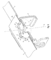
- a luminaire in the form of a ceiling-mounted luminaire is shown, which is fastened with a locking arrangement according to the invention on a ceiling.
- Fig. 8 shows components of the lamp in the manner of an exploded view.
- the light can be provided for attachment to a ceiling or on a wall. The following describes the case where the luminaire is intended for ceiling mounting. If the luminaire is intended for wall mounting, the description should be reinterpreted accordingly.
- a particular rail-like mounting element or support member 20 which is initially attached separately to the ceiling for mounting the lamp. Subsequently, the other lighting components are attached to the holding element 20, with the aid of the locking arrangement.
- the lever element 30 preferably has a grip tab 39 for easier handling.
- the shape of the grip tab 39 is preferably adapted to the shape or the surface of the lamp.
- the lever member 30 consists of one piece or formed in one piece.
- the pivot bearing 1 allows rotation of the lever member 30 about a rotation axis A.
- the ceiling runs horizontally.
- the axis of rotation A is oriented vertically in this case.
- the locking arrangement is generally also suitable for a corresponding attachment of a lamp to an otherwise inclined surface, so for example on an arbitrarily inclined wall element.
- the corresponding directions in the present description are to be reinterpreted accordingly.
- the lever member 30 can be moved back and forth by said rotation between a holding position and a release position, wherein the holding position for holding the other lighting components and in the release position, the other lighting components can be removed from the support member 20 and for mounting from the outside can be brought into the intended relative position relative to the retaining element 20 coming.
- Fig. 8 is the lever member 30 outlined in the holding position. For example, it can be provided that the release position relative to the holding position is rotated by 90 °.
- the lever member 30 For holding the other lighting components in the holding position, the lever member 30 has a locking element in the form of a support bracket 31, which engages behind a corresponding corresponding element on another lighting component or under.
- the locking arrangement thus represents a rotary latch.
- Fig. 4 shows a perspective view obliquely from below on the holding member 20 and the lever member 30 in the manner of an exploded view.
- the lever member 30 may further comprise a further support tab 31 ', which is formed with respect to the axis of rotation A of the first-mentioned support tab 31 opposite and preferably analog or symmetrical thereto.
- the holding member 20 may be a total of elongated, wherein the locking assembly and thus the pivot bearing 1 is disposed at one of the two end portions.
- a corresponding further locking arrangement is formed at the opposite end, opposite thereto, preferably analogous to the first-mentioned locking arrangement.
- the holding element 20 advantageously has at the other end region a further rotary bearing 1 'and a corresponding, further lever element 30', wherein the design is preferably symmetrical, in particular mirror-symmetrical to the first-mentioned locking arrangement.
- the retaining element 20 and the two mentioned locking arrangements thus form a mounting device for the luminaire.
- Such an elongated design of the retaining element 20 is particularly suitable in the case of an elongated lamp, as exemplified in Fig. 7 shown.
- the locking arrangement according to the invention is generally also in the case of a differently shaped lamp. If a luminaire has, for example, a rectangular or square basic shape, an embodiment with four locking arrangements could advantageously be provided, each of which is located in one of the four corner areas.
- Fig. 1 shows a perspective sectional view of the end portion of the lamp obliquely from above, wherein the holding member 20 and the other lighting components are shown in the provided for the operation of the lamp relative position.
- the lever member 30 is accordingly shown in the holding position.
- the further luminaire components in particular comprise a carrier element 40 of the luminaire, which comprises a projection 41 and a further projection 41 ', wherein for holding the other lighting components on the support member 20, the support bracket 31 engages under the projection 40 and the further support tab 31 'the further projection 41'.
- the support member 40 may be shaped like a profile while being aligned in parallel with the support member 20.
- the projection 41 and the further projection 41 ' are preferably shaped like a profile and oriented with their longitudinal axes parallel to the longitudinal axis of the holding element 20 when the lamp is mounted as intended.
- the support member 40 may advantageously be a device compartment 42 of the lamp may be formed, wherein the holding member 20 forms a cover for the equipment compartment 42 in the assembled state of the lamp.
- the holding member 20 forms a cover for the equipment compartment 42 in the assembled state of the lamp.
- Fig. 2 shows a further perspective view obliquely from above, wherein the sectional plane through the axis of rotation A of the pivot bearing 1 is placed.
- the rotary bearing 1 is a sliding bearing and comprises a guide element 2 and a guided element 3.
- the guide element 2 is preferably formed by the holding element 20 and the guided element 3 by the lever member 30th
- Fig. 3 shows a perspective view of the locking assembly in a separated form and Fig. 5 a cutaway view from diagonally above.
- the guide element 2 has a plurality, at least two, arranged on a circle K holes 4. Instead of the holes 4 and incomplete punching, so to speak "cracks" can be provided.
- Each of the holes 4 in this case has an edge region 5 pointing radially outward with respect to the circular line K , such that the edge regions 5 form guide surfaces for the guided element 3.
- the guided element 3 preferably has a circular opening 33, which is designed in such a way that, when the lever element 30 rotates about its axis of rotation A , its inner edge slides along the edge regions 5.
- the edge regions 5 thus act as a kind of "axle bolt". They are preferably formed by radially outwardly pointing webs or tabs 21, which in turn are formed by exemptions in the form of holes 4.
- the holes 4 may, for example, in a first approximation have a U-shape, wherein the two U-legs with respect to the circle K point towards the center. Between the U-legs then the tabs 21 are formed.
- the number of tabs 21 or the holes 4 can be adapted to the respective strength requirement. For example, between four and twelve holes 4 may be provided, so for example six or eight holes. 4
- the guide element 2 or the holding element 20 is preferably made of sheet metal and preferably the guided element 3 or the lever element 30 is made of sheet metal.
- the holes 4 in the guide element 2 can be advantageously formed by punching manufacturing technology.
- the circular opening 33 of the guided element 3 may be formed by punching.
- the case may advantageously be produced by a deformed plate, in which the deformation runs along the circular line K.
- the deformation can be advantageously formed by embossing or deep drawing.
- the locking arrangement further comprises a counter element 6 which is connected to the guide element 2 in such a way that the guided element 3 is arranged in an area outside the circular line K between the guide element 2 and the counter element 6.
- the counter element 6 is connected to the guide element 2 by welding or clinching. In this way, a suitable guide for the guided element 3 or the lever element 30 is formed with few components and low production costs.
- the deformation formed by embossing or deep-drawing is preferably such that an area 25 of the guide element 2 located within the circular line K is offset by one dimension from a region 26 located outside the circular line K , which is equal to a thickness of the guided element 3 plus a corresponding one Movement game for the guided element 3 is.
- At least one small embossment in one of the two said elements 6, 20 and at least one corresponding hole in the respective other of the two elements 6, 20 formed be.
- the counter element 6 in the direction of the axis A of the pivot bearing 1 preferably has a greater thickness than the guide element 2.
- the deformation is thereby advantageously formed manufacturing technology in the thinner of the two elements 2, 6.
- the counter-element 6 is thereby made thicker or stronger, so that holding forces occurring can be transferred particularly well.
- the deformation could alternatively be performed in the counter element 6 or in each of the two elements 2, 6 partially.
- the carrying tab 31 preferably has bent-over corners 35, 36 which act as guides or guiding surfaces when the carrying tab 31 moves under the projection 41 when the lamp is fastened to the holding element 20 serve. In this way it can be achieved that the lamp can be fixed with slight bias.
- the design may be such that the support bracket 31 is slightly bent over, so that when screwing a kind of dead center must be overcome. As a result, the risk of autonomous opening from the holding position can be reduced or even avoided.
- a corresponding fuse can be effected by a wire spring 37, as in Fig. 6 outlined.
- the counter-element 6 can also fulfill other functions, for example - be designed as an attack element for a pendulum - in the case of a pendant lamp.
- the counter element 6 can also be designed as a guide element to assist in the alignment of the other lighting components relative to the holding element 20 during assembly of the lamp; For example, this can - in the case of an elongated light - the longitudinal centering of the lamp be supported.
- the counter element 6 can-as shown by way of example in the figures-be formed by an angularly bent plate, with a leg formed thereby forming a stop element for a further luminaire component.
- the counter element 6 can also be configured as a receptacle of a rotation.
- the holding element 20 within the circular line K on preferably formed centrally about the axis A of the pivot bearing 2, through opening 29 for a connecting element V for fixing the holding member 20 on the ceiling.
- the connecting element V may in particular be a screw.
- the counter element 6 advantageously has a corresponding passage opening 69 for the connecting element V.
- the retaining element 20 is fastened to the ceiling by means of the connecting element V.
- the lamp is then electrically connected, in a third step, the other lighting components are aligned as intended relative to the holding member 20, wherein the lever member 30 is accordingly in the release position and in a fourth step, the lever member 30 from the release position rotated in the holding position, so that in this way the other lighting components are held on the holding element 20.
- the design of the lamp is such that - with mounted light - which is in the holding position lever member 30 is completely or almost completely within the normal projection of the other lighting components, so in normal view of the lamp is practically no longer visible.
- lever member 30 when the lever member 30 is in the release position, it preferably protrudes beyond the aforementioned projection of the other lighting components, so that it can be easily grasped.
- the locking arrangement according to the invention can be integrated into the luminaire in a particularly inconspicuous manner. It works very easy and safe. It can be made from very few individual parts.
Abstract
Description
Die Erfindung betrifft eine Verriegelungsanordnung für eine Leuchte, insbesondere für eine Anbauleuchte, wobei die Verriegelungsanordnung ein Halteelement und ein Hebelelement aufweist, das durch ein Drehlager drehbar an dem Halteelement gelagert ist. Weiterhin betrifft die Erfindung eine Leuchte mit einer solchen Verriegelungsanordnung.The invention relates to a locking arrangement for a lamp, in particular for a surface-mounted luminaire, wherein the locking arrangement comprises a holding element and a lever element which is rotatably supported by a pivot bearing on the holding element. Furthermore, the invention relates to a luminaire with such a locking arrangement.
Verriegelungsanordnungen, die ein Drehlager umfassen, sind bei Leuchten aus dem Stand der Technik in vielfältiger Form bekannt. Allerdings sind die bekannten Verriegelungsanordnungen vergleichsweise aufwändig in der Herstellung und komplex im Aufbau.Locking arrangements comprising a pivot bearing are known in various forms in the case of luminaires from the prior art. However, the known locking arrangements are relatively complex to manufacture and complex in construction.
Der Erfindung liegt die Aufgabe zugrunde, eine entsprechende verbesserte Verriegelungsanordnung anzugeben. Insbesondere soll die Verriegelungsanordnung bei besonders einfachem Aufbau eine sichere Funktionsweise zeigen. Außerdem soll eine Leuchte mit einer solchen Verriegelungsanordnung angegeben werden.The invention has for its object to provide a corresponding improved locking arrangement. In particular, the locking arrangement should show a safe operation in a particularly simple structure. In addition, a luminaire is to be specified with such a locking arrangement.
Diese Aufgabe wird gemäß der Erfindung mit den in den unabhängigen Ansprüchen genannten Gegenständen gelöst. Besondere Ausführungsarten der Erfindung sind in den abhängigen Ansprüchen angegeben.This object is achieved according to the invention with the objects mentioned in the independent claims. Particular embodiments of the invention are indicated in the dependent claims.
Gemäß der Erfindung ist eine Verriegelungsanordnung für eine Leuchte, insbesondere für eine Anbauleuchte, vorgesehen, die ein Halteelement und ein Hebelelement umfasst, das durch ein Drehlager drehbar an dem Halteelement gelagert ist. Das Drehlager ist dabei ein Gleitlager und weist ein Führungselement und ein geführtes Element auf, wobei das Führungselement wenigstens zwei, auf einer Kreislinie angeordnete Löcher oder unvollständige Stanzungen aufweist und jedes der Löcher bzw. jede der unvollständigen Stanzungen einen, mit Bezug auf die Kreislinie radial nach außen weisenden Randbereich aufweist, derart, dass die Randbereiche Führungsflächen für das geführte Element bilden.According to the invention, a locking arrangement for a luminaire, in particular for a surface-mounted luminaire, is provided, which comprises a holding element and a lever element which is rotatably supported by a pivot bearing on the holding element. The pivot bearing is a sliding bearing and has a guide element and a guided element, wherein the guide element has at least two, arranged on a circular line holes or incomplete punches and each of the holes or each of the incomplete punches one, with respect to the circular line radially to has outside edge region, such that the edge regions form guide surfaces for the guided element.
Durch diese Gestaltung lässt sich mit besonders geringem Herstellungs- und Materialaufwand eine Führung für das geführte Element bilden.As a result of this design, a guide for the guided element can be formed with particularly low production and material expenditure.
Vorzugsweise ist das Führungselement durch das Halteelement gebildet und das geführte Element durch das Hebelelement gebildet.Preferably, the guide element is formed by the holding element and the guided element is formed by the lever element.
Vorzugsweise bestehen das Führungselement und/oder das geführte Element aus Blech. Hierdurch ist eine besonders kostengünstige und einfache Herstellung der Verriegelungsanordnung ermöglicht.Preferably, the guide element and / or the guided element made of sheet metal. This allows a particularly cost-effective and simple production of the locking arrangement.
Weiterhin vorteilhaft mit Bezug auf die Herstellung ist das Führungselement durch eine verformte Platte gebildet, bei der die Verformung längs der Kreislinie verläuft. Insbesondere kann dabei die Verformung durch eine Prägung oder ein Tiefziehen gebildet sein.Further advantageously with respect to the manufacture, the guide element is formed by a deformed plate in which the deformation runs along the circular line. In particular, the deformation may be formed by embossing or deep-drawing.
Vorzugsweise weist die Verriegelungsanordnung außerdem ein Gegenelement auf, das derart mit dem Führungselement verbunden ist, dass das geführte Element in einem Bereich außerhalb der Kreislinie zwischen dem Führungselement und dem Gegenelement angeordnet ist. Hierdurch lässt sich die Verriegelungsanordnung mit besonders wenigen Bauteilen ausführen.Preferably, the locking arrangement further comprises a counter-element which is connected to the guide element such that the guided element is arranged in an area outside the circular line between the guide element and the counter-element. As a result, the locking arrangement can be carried out with particularly few components.
Herstellungstechnisch vorteilhaft ist dabei das Gegenelement mit dem Führungselement durch Schweißen oder Clinchen verbunden.In terms of manufacturing technology, the counter element is connected to the guide element by welding or clinching.
Vorzugsweise weist dabei - innerhalb der Kreislinie betrachtet - das Gegenelement in Richtung der Achse des Drehlagers eine größere Stärke auf als das Führungselement. Hierdurch lässt sich erzielen, dass die auftretenden Haltekräfte besonders gut übertragen werden können.Preferably, in this case - viewed within the circle - the counter element in the direction of the axis of the pivot bearing on a greater strength than the guide element. This makes it possible to achieve that the holding forces that occur can be transmitted particularly well.
Gemäß einem weiteren Aspekt der Erfindung ist eine Leuchte mit einer erfindungsgemäßen Verriegelungsanordnung vorgesehen. Die Verriegelungsanordnung ist dabei vorzugsweise zur Halterung der Leuchte an einer Decke oder Wand ausgestaltet, wobei das Halteelement dafür vorgesehen ist, an der Decke bzw. an der Wand befestigt zu werden. Auch eine umgekehrte Montage wäre denkbar.According to a further aspect of the invention, a luminaire is provided with a locking arrangement according to the invention. The locking arrangement is preferably designed for mounting the lamp to a ceiling or wall, wherein the holding element is provided for, at the Ceiling or to be attached to the wall. A reverse assembly would be conceivable.
Vorzugsweise weist das Halteelement innerhalb der Kreislinie eine, vorzugsweise zentrisch um die Achse des Drehlagers gebildete, Durchgangsöffnung für ein Verbindungselement zur Fixierung des Halteelements an der Decke bzw. Wand auf. Auf diese Weise lässt sich erzielen, dass der Kraftfluss von der Leuchte zur Decke bzw. zur Wand direkt bzw. unmittelbar von dem Hebelelement auf das Verbindungselement, also beispielsweise eine Schraube, führt. Dabei wird keine Verbindung zu anderen Bauteilen beansprucht.Preferably, the retaining element has within the circular line on, preferably centrally about the axis of the pivot bearing formed, through opening for a connecting element for fixing the retaining element to the ceiling or wall. In this way it can be achieved that the power flow from the lamp to the ceiling or to the wall directly or directly from the lever element on the connecting element, so for example a screw leads. No connection to other components is claimed.
Die Verriegelungsanordnung ist vorzugsweise dazu ausgestaltet, ein Trägerelement der Leuchte an dem Halteelement zu halten. Die Verriegelungsanordnung eignet sich aufgrund ihres Aufbaus besonders gut zur Halterung entsprechender Gewichte. Bei der Leuchte kann es sich beispielsweise um eine 2 oder 3 m lange Leuchte handeln, die ein entsprechend hohes Gewicht aufweist.The locking arrangement is preferably configured to hold a support element of the lamp to the holding element. The locking arrangement is particularly well suited for holding corresponding weights due to their structure. The luminaire may be, for example, a 2 or 3 m long luminaire, which has a correspondingly high weight.
Vorzugsweise weist das Hebelelement eine Traglasche auf, die für ein Untergreifen eines Vorsprungs des Trägerelements zum Halten des Trägerelements an dem Halteelement ausgestaltet ist.Preferably, the lever element has a support lug, which is designed to engage under a projection of the carrier element for holding the carrier element on the holding element.
Vorzugsweise ist die Leuchte länglich, so dass sie zwei Endbereiche aufweist, wobei die Verriegelungsanordnung an einem der beiden Endbereiche angeordnet ist und an dem hierzu gegenüberliegenden, anderen Endbereich eine weitere Verriegelungsanordnung angeordnet ist, die vorzugsweise analog zu der zuerst genannten Verriegelungsanordnung ausgebildet ist, insbesondere symmetrisch hierzu. In diesem Fall eignet sich die Verriegelungsanordnung besonders gut zur Halterung der Leuchte.Preferably, the lamp is elongate, so that it has two end regions, wherein the locking arrangement is arranged on one of the two end regions and on the opposite end, another end locking arrangement is arranged, which is preferably analogous to the first-mentioned locking arrangement, in particular symmetrically For this. In this case, the locking arrangement is particularly well suited for holding the lamp.
Die Erfindung wird im Folgenden anhand eines Ausführungsbeispiels und mit Bezug auf die Zeichnungen näher erläutert. Es zeigen:
- Fig. 1
- eine perspektivische Schnittdarstellung zu einer erfindungsgemäßen Verriegelungsanordnung als Bestandteil einer Leuchte,
- Fig. 2
- eine entsprechende Darstellung, wobei die Schnittebene durch die Drehachse des Drehlagers der Verriegelungsanordnung geführt ist,
- Fig. 3
- eine perspektivische Skizze von schräg oben zu der Verriegelungsanordnung in separierter Form,
- Fig. 4
- eine Skizze von schräg unten nach Art einer Explosionsdarstellung,
- Fig. 5
- eine detailliertere perspektivische Schnittdarstellung von schräg oben, bei der der Schnitt durch die Drehachse des Drehlagers geführt ist,
- Fig. 6
- eine weitere perspektivische Darstellung von schräg unten,
- Fig. 7
- eine Leuchte, die mit einer erfindungsgemäßen Verriegelungsanordnung an einer Decke befestigt ist und
- Fig. 8
- eine Skizze der Leuchte nach Art einer Explosionsdarstellung.
- Fig. 1
- 3 a perspective sectional view of a locking arrangement according to the invention as part of a luminaire,
- Fig. 2
- a corresponding representation, wherein the cutting plane is guided through the axis of rotation of the pivot bearing of the locking arrangement,
- Fig. 3
- a perspective sketch obliquely from above to the locking arrangement in a separate form,
- Fig. 4
- a sketch from diagonally below in the manner of an exploded view,
- Fig. 5
- a more detailed perspective sectional view obliquely from above, in which the section is guided through the axis of rotation of the pivot bearing,
- Fig. 6
- another perspective view from diagonally below,
- Fig. 7
- a luminaire, which is fastened with a locking arrangement according to the invention on a ceiling and
- Fig. 8
- a sketch of the lamp in the manner of an exploded view.
In
Zur Befestigung der Leuchte an der Decke dient ein insbesondere schienenartiges Montageelement bzw. Halteelement 20, das zur Montage der Leuchte zunächst separat an der Decke befestigt wird. Anschließend werden an dem Halteelement 20 die weiteren Leuchtenbauteile befestigt, und zwar mit Hilfe der Verriegelungsanordnung.To attach the lamp to the ceiling is a particular rail-like mounting element or
Diese umfasst neben dem Halteelement 20 ein Hebelelement 30, das durch ein Drehlager 1 drehbar an dem Halteelement 20 gelagert ist, wie in
Herstellungstechnisch vorteilhaft ist das Hebelelement 30 aus einem Stück bestehend bzw. einteilig gebildet.Manufacturing technology advantageous, the
Das Drehlager 1 ermöglicht eine Drehung des Hebelelements 30 um eine Drehachse A. Im hier gezeigten Fall verläuft die Decke horizontal. Die Drehachse A ist in diesem Fall senkrecht orientiert.The pivot bearing 1 allows rotation of the
Allerdings eignet sich die Verriegelungsanordnung allgemein auch für eine entsprechende Befestigung einer Leuchte an einer anderweitig geneigten Fläche, also beispielsweise an einem beliebig geneigten Wandelement. Die entsprechenden Richtungsangaben in der vorliegenden Beschreibung sind gegebenenfalls entsprechend umzudeuten.However, the locking arrangement is generally also suitable for a corresponding attachment of a lamp to an otherwise inclined surface, so for example on an arbitrarily inclined wall element. The corresponding directions in the present description are to be reinterpreted accordingly.
Das Hebelelement 30 lässt sich durch die besagte Drehung zwischen einer Halteposition und einer Löseposition hin- und her bewegen, wobei die Halteposition zur Halterung der weiteren Leuchtenbauteile dient und in der Löseposition die weiteren Leuchtenbauteile von dem Halteelement 20 entfernt werden können bzw. zur Montage von außen kommend in die vorgesehene Relativposition gegenüber dem Halteelement 20 gebracht werden können. In
Zur Halterung der weiteren Leuchtenbauteile in der Halteposition weist das Hebelelement 30 ein Verriegelungselement in Form einer Traglasche 31 auf, die ein hierzu entsprechend korrespondierendes Element an einem weiteren Leuchtenbauteil hinter- bzw. untergreift. Die Verriegelungsanordnung stellt somit einen Drehriegelverschluss dar.For holding the other lighting components in the holding position, the
Wie in
Das Halteelement 20 und die beiden genannten Verriegelungsanordnungen bilden somit eine Montagevorrichtung für die Leuchte.The retaining
Eine derartige längliche Gestaltung des Halteelements 20 eignet sich besonders im Fall einer länglichen Leuchte, wie exemplarisch in
Die weiteren Leuchtenbauteile umfassen insbesondere ein Trägerelement 40 der Leuchte, das einen Vorsprung 41 und einen weiteren Vorsprung 41' umfasst, wobei zur Halterung der weiteren Leuchtenbauteile an dem Halteelement 20 die Traglasche 31 den Vorsprung 40 untergreift und die weitere Traglasche 31' den weiteren Vorsprung 41'. Wie gezeigt, kann das Trägerelement 40 profilartig gestaltet und dabei parallel zu dem Halteelement 20 ausgerichtet vorgesehen sein. Dementsprechend sind der Vorsprung 41 und der weitere Vorsprung 41' vorzugsweise profilartig geformt und mit ihrem Längsachsen jeweils parallel zu der Längsachse des Halteelements 20 orientiert, wenn die Leuchte wie vorgesehen montiert ist.The further luminaire components in particular comprise a
Durch das Trägerelement 40 kann vorteilhaft ein Geräteraum 42 der Leuchte gebildet sein, wobei das Halteelement 20 im montierten Zustand der Leuchte eine Abdeckung für den Geräteraum 42 bildet. Beim Abnehmen der Leuchte von der Decke wird auf diese Weise automatisch der Zugang zum Geräteraum 42 eröffnet bzw. bei Montage der Leuchte der Geräteraum 42 abgedeckt.By the
Im Folgenden wird nun näher auf die Verriegelungsanordnung an sich eingegangen.The following will now be discussed in more detail on the locking arrangement itself.
Das Drehlager 1 ist ein Gleitlager und umfasst ein Führungselement 2 und ein geführtes Element 3. Das Führungselement 2 ist vorzugsweise durch das Halteelement 20 gebildet und das geführte Element 3 durch das Hebelelement 30.The rotary bearing 1 is a sliding bearing and comprises a
Die Randbereiche 5 fungieren also sozusagen als "Achsbolzen". Sie sind vorzugsweise durch radial nach außen weisende Stege bzw. Laschen 21 gebildet, die wiederum durch Freistellungen in Form der Löcher 4 gebildet sind. Die Löcher 4 können beispielsweise in erster Näherung eine U-Form aufweisen, wobei die beiden U-Schenkel mit Bezug auf die Kreislinie K zur Mitte hin weisen. Zwischen den U-Schenkeln sind dann die Laschen 21 gebildet.The
Die Anzahl der Laschen 21 bzw. der Löcher 4 kann an das jeweilige Festigkeitserfordemis angepasst sein. Beispielsweise können zwischen vier und zwölf Löcher 4 vorgesehen sein, also beispielsweise sechs oder acht Löcher 4.The number of
Zur Herstellung kann vorgesehen sein, dass in einem ersten Schritt die Löcher 4 gestanzt werden und in einem darauffolgenden, zweiten Schritt die Verformung hergestellt wird.For the production it can be provided that in a first step the
Vorzugsweise besteht das Führungselement 2 bzw. das Halteelement 20 aus Blech und vorzugsweise besteht das geführte Element 3 bzw. das Hebelelement 30 aus Blech. Die Löcher 4 in dem Führungselement 2 können herstellungstechnisch vorteilhaft durch Ausstanzen gebildet sein. Ebenso kann die kreisrunde Öffnung 33 des geführten Elements 3 durch Ausstanzen gebildet sein.The
Wie im gezeigten Beispiel weiterhin der Fall, kann herstellungstechnisch vorteilhaft das Führungselement 2 durch eine verformte Platte gebildet sein, bei der die Verformung längs der Kreislinie K verläuft. Die Verformung kann vorteilhaft durch eine Prägung oder ein Tiefziehen gebildet sein.As in the example shown, the case may advantageously be produced by a deformed plate, in which the deformation runs along the circular line K. The deformation can be advantageously formed by embossing or deep drawing.
Durch ein entsprechendes Verformen einer Platte, die keine entsprechenden Löcher aufweist, würde schwerlich eine geeignete kreiszylindrische Führungsfläche gebildet werden können; bei einem derartigen Verformen sind stets gewisse Toleranzen zu berücksichtigen. Durch die Löcher 4 lässt sich erzielen, dass herstellungstechnisch vorteilhaft dennoch eine entsprechend exakte Führung für das geführte Element 3 bzw. das Hebelelement 30 gewährleistet werden kann.By a corresponding deformation of a plate having no corresponding holes, a suitable circular cylindrical guide surface would be difficult to be formed; In such a deformation always certain tolerances are taken into account. Through the
Wie im gezeigten Beispiel der Fall, weist die Verriegelungsanordnung weiterhin ein Gegenelement 6 auf, das derart mit dem Führungselement 2 verbunden ist, dass das geführte Element 3 in einem Bereich außerhalb der Kreislinie K zwischen dem Führungselement 2 und dem Gegenelement 6 angeordnet ist. Vorzugsweise ist dabei das Gegenelement 6 mit dem Führungselement 2 durch Schweißen oder Clinchen verbunden. Auf diese Weise ist mit wenigen Bauteilen und geringem Herstellungsaufwand eine geeignete Führung für das geführte Element 3 bzw. das Hebelelement 30 gebildet.As in the example shown, the locking arrangement further comprises a
Dementsprechend ist die durch Prägung oder Tiefziehen gebildete Verformung vorzugsweise derart, dass ein innerhalb der Kreislinie K befindlicher Bereich 25 des Führungselements 2 um ein Maß gegenüber einem außerhalb der Kreislinie K befindlichen Bereich 26 versetzt ist, das gleich einer Stärke des geführten Elements 3 zuzüglich einem entsprechendem Bewegungsspiel für das geführte Element 3 ist.Accordingly, the deformation formed by embossing or deep-drawing is preferably such that an
Um ein Zentrieren des Gegenelements 6 relativ zu dem Halteelement 20 bei der Herstellung der Verriegelungsanordnung zu erleichtern, kann wenigstens eine kleine Prägung in einem der beiden genannten Elemente 6, 20 und wenigstens ein dazu korrespondierendes Loch in dem betreffenden anderen der beiden Elemente 6, 20 ausgebildet sein.In order to facilitate centering of the
Innerhalb der Kreislinie K betrachtet weist das Gegenelement 6 in Richtung der Achse A des Drehlagers 1 vorzugsweise eine größere Stärke auf als das Führungselement 2. Die Verformung ist hierdurch herstellungstechnisch vorteilhaft in dem dünneren der beiden Elemente 2, 6 gebildet. Das Gegenelement 6 ist dadurch dicker bzw. stärker ausgebildet, so dass auftretende Haltekräfte besonders gut übertragen werden können.Considered within the circle line K, the
Grundsätzlich könnte jedoch die Verformung alternativ in dem Gegenelement 6 ausgeführt sein oder in jedem der beiden Elemente 2, 6 teilweise.In principle, however, the deformation could alternatively be performed in the
Wie in
Weiterhin kann die Gestaltung derart sein, dass die Traglasche 31 ein wenig überbogen ist, so dass beim Eindrehen eine Art Totpunkt überwunden werden muss. Dadurch lässt sich die Gefahr eines selbstständigen Öffnens aus der Halteposition heraus verringern oder gar vermeiden. Alternativ oder ergänzend kann eine entsprechende Sicherung durch eine Drahtfeder 37 bewirkt werden, wie in
Das Gegenelement 6 kann außerdem weitere Funktionen erfüllen, zum Beispiel - im Fall einer Pendelleuchte - als Angriffselement für ein Pendel ausgestaltet sein.The counter-element 6 can also fulfill other functions, for example - be designed as an attack element for a pendulum - in the case of a pendant lamp.
Das Gegenelement 6 kann auch als Führungselement zur Unterstützung bei der Ausrichtung der weiteren Leuchtenbauteile gegenüber dem Halteelement 20 bei der Montage der Leuchte ausgebildet sein; beispielsweise kann hierdurch - im Fall einer länglichen Leuchte - die Längszentrierung der Leuchte unterstützt sein. Das Gegenelement 6 kann hierzu - wie in den Figuren beispielhaft gezeigt - durch eine winkelförmig gebogene Platte gebildet sein, wobei ein hierdurch gebildeter Schenkel ein Anschlagelement für ein weiteres Leuchtenbauteil bildet.The
Das Gegenelement 6 kann auch als Aufnahme einer Verdrehsicherung ausgestaltet sein.The
Vorzugsweise weist das Halteelement 20 innerhalb der Kreislinie K eine, vorzugsweise zentrisch um die Achse A des Drehlagers 2 gebildete, Durchgangsöffnung 29 für ein Verbindungselement V zur Fixierung des Halteelements 20 an der Decke auf. Hierdurch ist ein besonders unmittelbarer Kraftfluss von dem Hebelelement 30 über das Verbindungselement V an die Decke ermöglicht. Bei dem Verbindungselement V kann es sich insbesondere um eine Schraube handeln.Preferably, the holding
Dementsprechend weist auch das Gegenelement 6 vorteilhaft eine entsprechende Durchgangsöffnung 69 für das Verbindungselement V auf.Accordingly, the
Zur Montage der Leuchte an einer Decke kann vorgesehen sein, dass in einem ersten Schritt das Halteelement 20 mit Hilfe des Verbindungselements V an der Decke befestigt wird. In einem zweiten Schritt wird die Leuchte dann elektrisch angeschlossen, in einem dritten Schritt werden die weiteren Leuchtenbauteile wie vorgesehen relativ zu dem Halteelement 20 ausgerichtet, wobei sich das Hebelelement 30 dementsprechend in der Löseposition befindet und in einem vierten Schritt wird das Hebelelement 30 aus der Löseposition in die Halteposition gedreht, so dass hierdurch die weiteren Leuchtenbauteile an dem Halteelement 20 gehalten sind.For mounting the lamp to a ceiling, it may be provided that in a first step the retaining
Vorzugsweise ist die Gestaltung der Leuchte dabei derart, dass sich - bei montierter Leuchte - das in der Halteposition befindliche Hebelelement 30 vollständig oder nahezu vollständig innerhalb der normalen Projektion der weiteren Leuchtenbauteile befindet, also bei normaler Betrachtung der Leuchte praktisch nicht mehr sichtbar ist.Preferably, the design of the lamp is such that - with mounted light - which is in the holding
Wenn sich das Hebelelement 30 jedoch in der Löseposition befindet, ragt es vorzugsweise neben der genannten Projektion der weiteren Leuchtenbauteile heraus, so dass es sich gut ergreifen lässt.However, when the
Im gezeigten Beispiel weist das Hebelelement 30, dem Drehlager 1 gegenüberliegend, einen kleinen, leicht gebogenen Endbereich auf, der ein Ergreifen des Hebelelements 30 erleichtert, wenn sich das Hebelelement 30, bei montierter Leuchte, in der Halteposition befindet. Hierdurch ist eine Demontage der Leuchte erleichtert.In the example shown, the
Die erfindungsgemäße Verriegelungsanordnung lässt sich insbesondere besonders unauffällig in die Leuchte integrieren. Sie funktioniert besonders einfach und sicher. Sie lässt sich aus besonders wenigen Einzelteilen herstellen.The locking arrangement according to the invention can be integrated into the luminaire in a particularly inconspicuous manner. It works very easy and safe. It can be made from very few individual parts.
Claims (14)
dadurch gekennzeichnet,
dass das Drehlager (1) ein Gleitlager ist und ein Führungselement (2) und ein geführtes Element (3) aufweist, wobei das Führungselement (2) wenigstens zwei, auf einer Kreislinie (K) angeordnete Löcher (4) oder unvollständige Stanzungen aufweist und jedes der Löcher (4) bzw. jede der unvollständigen Stanzungen einen, mit Bezug auf die Kreislinie (K) radial nach außen weisenden Randbereich (5) aufweist, derart, dass die Randbereiche (5) Führungsflächen für das geführte Element (3) bilden.
characterized,
in that the pivot bearing (1) is a slide bearing and has a guide element (2) and a guided element (3), wherein the guide element (2) has at least two holes (4) arranged on a circular line ( K ) or incomplete punches and each of the holes (4) or each of the incomplete punches has a, with respect to the circular line ( K ) radially outwardly facing edge region (5), such that the edge regions (5) guide surfaces for the guided element (3).
bei der das Führungselement (2) durch das Halteelement (20) gebildet ist und das geführte Element (3) durch das Hebelelement (30) gebildet ist.Locking arrangement according to claim 1,
in which the guide element (2) is formed by the holding element (20) and the guided element (3) is formed by the lever element (30).
bei der das Führungselement (2) und/oder das geführte Element (3) aus Blech bestehen.Locking arrangement according to claim 1 or 2,
in which the guide element (2) and / or the guided element (3) consist of sheet metal.
bei der das Führungselement (2) durch eine verformte Platte gebildet ist, bei der die Verformung längs der Kreislinie (K) verläuft.Locking arrangement according to one of the preceding claims,
in which the guide element (2) is formed by a deformed plate, in which the deformation runs along the circular line ( K ).
bei der die Verformung durch eine Prägung oder ein Tiefziehen gebildet ist.Locking arrangement according to claim 4,
in which the deformation is formed by embossing or deep drawing.
bei der das Gegenelement (6) mit dem Führungselement (2) durch Schweißen oder Clinchen verbunden ist.Locking arrangement according to claim 6,
in which the counter element (6) is connected to the guide element (2) by welding or clinching.
bei der innerhalb der Kreislinie (K) betrachtet das Gegenelement (6) in Richtung der Achse (A) des Drehlagers (1) eine größere Stärke aufweist als das Führungselement (2).Locking arrangement according to claim 6 or 7,
when viewed within the circular line ( K ), the counter element (6) in the direction of the axis (A) of the pivot bearing (1) has a greater thickness than the guide element (2).
bei der die Verriegelungsanordnung zur Halterung der Leuchte an einer Decke oder Wand ausgestaltet ist und das Halteelement (20) dafür vorgesehen ist, an der Decke bzw. an der Wand befestigt zu werden.Luminaire according to claim 9,
wherein the locking arrangement for mounting the lamp is configured on a ceiling or wall and the holding element (20) is provided to be attached to the ceiling or on the wall.
bei der das Halteelement (20) innerhalb der Kreislinie (K) eine, vorzugsweise zentrisch um die Achse (A) des Drehlagers (2) gebildete, Durchgangsöffnung (29) für ein Verbindungselement (V) zur Fixierung des Halteelements (20) an der Decke bzw. Wand aufweist.Luminaire according to claim 10,
in which the retaining element (20) within the circular line ( K ), preferably centrally around the axis ( A ) of the pivot bearing (2) formed through opening (29) for a connecting element ( V ) for fixing the retaining element (20) on the ceiling or wall.
bei der die Verriegelungsanordnung dazu ausgestaltet ist, ein Trägerelement (40) der Leuchte an dem Halteelement (20) zu halten.Luminaire according to claim 10 or 11,
in which the locking arrangement is designed to hold a carrier element (40) of the luminaire on the holding element (20).
bei der das Hebelelement (30) eine Traglasche (31) aufweist, die für ein Untergreifen eines Vorsprungs (41) des Trägerelements (40) zum Halten des Trägerelements (40) an dem Halteelement (20) ausgestaltet ist.Luminaire according to claim 12,
in that the lever element (30) has a support lug (31) which is designed to engage under a projection (41) of the carrier element (40) for holding the carrier element (40) on the holding element (20).
die länglich ist, so dass sie zwei Endbereiche aufweist, wobei die Verriegelungsanordnung an einem der beiden Endbereiche angeordnet ist und an dem hierzu gegenüberliegenden, anderen Endbereich eine weitere Verriegelungsanordnung angeordnet ist, die vorzugsweise analog zu der zuerst genannten Verriegelungsanordnung ausgebildet ist, insbesondere symmetrisch hierzu.Luminaire according to one of claims 10 to 13,
which is elongated so that it has two end regions, wherein the locking arrangement is arranged on one of the two end regions and on the opposite end, another end locking arrangement is arranged, which is preferably analogous to the first-mentioned locking arrangement, in particular symmetrically thereto.
Applications Claiming Priority (1)
| Application Number | Priority Date | Filing Date | Title |
|---|---|---|---|
| DE201220103668 DE202012103668U1 (en) | 2012-09-25 | 2012-09-25 | Locking arrangement for a lamp, as well as light with a locking arrangement |
Publications (2)
| Publication Number | Publication Date |
|---|---|
| EP2711623A1 true EP2711623A1 (en) | 2014-03-26 |
| EP2711623B1 EP2711623B1 (en) | 2015-03-04 |
Family
ID=49237074
Family Applications (1)
| Application Number | Title | Priority Date | Filing Date |
|---|---|---|---|
| EP20130185740 Active EP2711623B1 (en) | 2012-09-25 | 2013-09-24 | Locking assembly for a lamp, and luminaire with a locking assembly |
Country Status (2)
| Country | Link |
|---|---|
| EP (1) | EP2711623B1 (en) |
| DE (1) | DE202012103668U1 (en) |
Citations (4)
| Publication number | Priority date | Publication date | Assignee | Title |
|---|---|---|---|---|
| DE1880355U (en) * | 1963-08-16 | 1963-10-10 | Norka Norddeutsche Kunststoff | SURFACE BRACKET ON ELECTRICAL DEVICES. |
| US3283145A (en) * | 1962-08-24 | 1966-11-01 | Trilux Lenze Gmbh & Co Kg | Lamp fitting |
| DE2460454A1 (en) * | 1974-12-20 | 1976-06-24 | Licentia Gmbh | Rotary locking device for lighting units - has crank activator and matching projections in cover sheet aperture |
| DE9315023U1 (en) * | 1993-10-04 | 1993-12-23 | Meyer A & H Leuchten Bueroelek | Fastening element for a pre-wired, electrical unit on a profile rail |
Family Cites Families (1)
| Publication number | Priority date | Publication date | Assignee | Title |
|---|---|---|---|---|
| DE202004015808U1 (en) * | 2004-10-13 | 2005-11-17 | Lite-Licht Gmbh | Mounting for a lighting unit on a surface uses a bracket fixed to the surface that can pivot about a vertical axis |
-
2012
- 2012-09-25 DE DE201220103668 patent/DE202012103668U1/en not_active Expired - Lifetime
-
2013
- 2013-09-24 EP EP20130185740 patent/EP2711623B1/en active Active
Patent Citations (4)
| Publication number | Priority date | Publication date | Assignee | Title |
|---|---|---|---|---|
| US3283145A (en) * | 1962-08-24 | 1966-11-01 | Trilux Lenze Gmbh & Co Kg | Lamp fitting |
| DE1880355U (en) * | 1963-08-16 | 1963-10-10 | Norka Norddeutsche Kunststoff | SURFACE BRACKET ON ELECTRICAL DEVICES. |
| DE2460454A1 (en) * | 1974-12-20 | 1976-06-24 | Licentia Gmbh | Rotary locking device for lighting units - has crank activator and matching projections in cover sheet aperture |
| DE9315023U1 (en) * | 1993-10-04 | 1993-12-23 | Meyer A & H Leuchten Bueroelek | Fastening element for a pre-wired, electrical unit on a profile rail |
Also Published As
| Publication number | Publication date |
|---|---|
| DE202012103668U1 (en) | 2014-01-07 |
| EP2711623B1 (en) | 2015-03-04 |
Similar Documents
| Publication | Publication Date | Title |
|---|---|---|
| AT515988B1 (en) | Luminaire, arrangement for a grid ceiling, method for mounting a lamp, method for dismantling a lamp, as well as dismantling tool | |
| EP2637486B1 (en) | Electrical device with a casing for an electrical device with a holding and clamping device | |
| EP2986090A1 (en) | Housing with a bottom section and a top section | |
| EP2264358B1 (en) | Luminaire and lightband | |
| AT515647B1 (en) | lamp | |
| EP2929234B1 (en) | Recess-mounted light | |
| EP2893248B1 (en) | Fitting ring for fitting a recessed lamp and a recessed lamp with fitting ring | |
| DE202006020773U1 (en) | suspension | |
| WO2007121834A1 (en) | Fixing system, in particular for lamps | |
| EP2711623B1 (en) | Locking assembly for a lamp, and luminaire with a locking assembly | |
| EP3608588B1 (en) | Holder spring for light | |
| DE102017103769A1 (en) | Fastening device and mounting assembly | |
| DE102019219288A1 (en) | Quick assembly connector, arrangement and method for securing a quick assembly connector | |
| AT515601A2 (en) | System for receiving light modules and method for its production | |
| EP0927308A1 (en) | Lock-in device for a straight moving building component | |
| EP1688666A2 (en) | Casing and profile for such a casing | |
| EP2957814A1 (en) | Illumination system | |
| DE3244516A1 (en) | Device for detachably connecting the ballast frame to the rail of a lighting fixture, e.g. for fluorescent lamps | |
| DE102016119999B3 (en) | Kit for a cable cover outlet | |
| EP3693618B1 (en) | Assembly for multiple quick release and multiple quick opening | |
| DE2236108C2 (en) | Switch casing with interlocking elements - has base with locking flange and locking fingers and cover with locking shoulder | |
| EP2568215A2 (en) | Light strip | |
| EP2768238B1 (en) | Ceiling loudspeaker with a cover | |
| EP3558058B1 (en) | Piece of furniture comprising a cable feedthrough and method for forming a cable feedthrough | |
| DE10152149B4 (en) | electric motor |
Legal Events
| Date | Code | Title | Description |
|---|---|---|---|
| PUAI | Public reference made under article 153(3) epc to a published international application that has entered the european phase |
Free format text: ORIGINAL CODE: 0009012 |
|
| AK | Designated contracting states |
Kind code of ref document: A1 Designated state(s): AL AT BE BG CH CY CZ DE DK EE ES FI FR GB GR HR HU IE IS IT LI LT LU LV MC MK MT NL NO PL PT RO RS SE SI SK SM TR |
|
| AX | Request for extension of the european patent |
Extension state: BA ME |
|
| 17P | Request for examination filed |
Effective date: 20140722 |
|
| RBV | Designated contracting states (corrected) |
Designated state(s): AL AT BE BG CH CY CZ DE DK EE ES FI FR GB GR HR HU IE IS IT LI LT LU LV MC MK MT NL NO PL PT RO RS SE SI SK SM TR |
|
| GRAP | Despatch of communication of intention to grant a patent |
Free format text: ORIGINAL CODE: EPIDOSNIGR1 |
|
| RIC1 | Information provided on ipc code assigned before grant |
Ipc: F21V 21/02 20060101AFI20140909BHEP Ipc: F21V 17/18 20060101ALN20140909BHEP |
|
| INTG | Intention to grant announced |
Effective date: 20140930 |
|
| GRAS | Grant fee paid |
Free format text: ORIGINAL CODE: EPIDOSNIGR3 |
|
| GRAA | (expected) grant |
Free format text: ORIGINAL CODE: 0009210 |
|
| AK | Designated contracting states |
Kind code of ref document: B1 Designated state(s): AL AT BE BG CH CY CZ DE DK EE ES FI FR GB GR HR HU IE IS IT LI LT LU LV MC MK MT NL NO PL PT RO RS SE SI SK SM TR |
|
| REG | Reference to a national code |
Ref country code: GB Ref legal event code: FG4D Free format text: NOT ENGLISH |
|
| REG | Reference to a national code |
Ref country code: CH Ref legal event code: NV Representative=s name: FIAMMENGHI-FIAMMENGHI, CH Ref country code: CH Ref legal event code: EP |
|
| REG | Reference to a national code |
Ref country code: IE Ref legal event code: FG4D Free format text: LANGUAGE OF EP DOCUMENT: GERMAN |
|
| REG | Reference to a national code |
Ref country code: AT Ref legal event code: REF Ref document number: 714217 Country of ref document: AT Kind code of ref document: T Effective date: 20150415 |
|
| REG | Reference to a national code |
Ref country code: DE Ref legal event code: R096 Ref document number: 502013000415 Country of ref document: DE Effective date: 20150416 |
|
| REG | Reference to a national code |
Ref country code: NL Ref legal event code: VDEP Effective date: 20150304 |
|
| PG25 | Lapsed in a contracting state [announced via postgrant information from national office to epo] |
Ref country code: SE Free format text: LAPSE BECAUSE OF FAILURE TO SUBMIT A TRANSLATION OF THE DESCRIPTION OR TO PAY THE FEE WITHIN THE PRESCRIBED TIME-LIMIT Effective date: 20150304 Ref country code: ES Free format text: LAPSE BECAUSE OF FAILURE TO SUBMIT A TRANSLATION OF THE DESCRIPTION OR TO PAY THE FEE WITHIN THE PRESCRIBED TIME-LIMIT Effective date: 20150304 Ref country code: FI Free format text: LAPSE BECAUSE OF FAILURE TO SUBMIT A TRANSLATION OF THE DESCRIPTION OR TO PAY THE FEE WITHIN THE PRESCRIBED TIME-LIMIT Effective date: 20150304 Ref country code: LT Free format text: LAPSE BECAUSE OF FAILURE TO SUBMIT A TRANSLATION OF THE DESCRIPTION OR TO PAY THE FEE WITHIN THE PRESCRIBED TIME-LIMIT Effective date: 20150304 Ref country code: NO Free format text: LAPSE BECAUSE OF FAILURE TO SUBMIT A TRANSLATION OF THE DESCRIPTION OR TO PAY THE FEE WITHIN THE PRESCRIBED TIME-LIMIT Effective date: 20150604 Ref country code: HR Free format text: LAPSE BECAUSE OF FAILURE TO SUBMIT A TRANSLATION OF THE DESCRIPTION OR TO PAY THE FEE WITHIN THE PRESCRIBED TIME-LIMIT Effective date: 20150304 |
|
| REG | Reference to a national code |
Ref country code: LT Ref legal event code: MG4D |
|
| PG25 | Lapsed in a contracting state [announced via postgrant information from national office to epo] |
Ref country code: LV Free format text: LAPSE BECAUSE OF FAILURE TO SUBMIT A TRANSLATION OF THE DESCRIPTION OR TO PAY THE FEE WITHIN THE PRESCRIBED TIME-LIMIT Effective date: 20150304 Ref country code: GR Free format text: LAPSE BECAUSE OF FAILURE TO SUBMIT A TRANSLATION OF THE DESCRIPTION OR TO PAY THE FEE WITHIN THE PRESCRIBED TIME-LIMIT Effective date: 20150605 Ref country code: RS Free format text: LAPSE BECAUSE OF FAILURE TO SUBMIT A TRANSLATION OF THE DESCRIPTION OR TO PAY THE FEE WITHIN THE PRESCRIBED TIME-LIMIT Effective date: 20150304 |
|
| PG25 | Lapsed in a contracting state [announced via postgrant information from national office to epo] |
Ref country code: NL Free format text: LAPSE BECAUSE OF FAILURE TO SUBMIT A TRANSLATION OF THE DESCRIPTION OR TO PAY THE FEE WITHIN THE PRESCRIBED TIME-LIMIT Effective date: 20150304 |
|
| REG | Reference to a national code |
Ref country code: FR Ref legal event code: PLFP Year of fee payment: 3 |
|
| PG25 | Lapsed in a contracting state [announced via postgrant information from national office to epo] |
Ref country code: SK Free format text: LAPSE BECAUSE OF FAILURE TO SUBMIT A TRANSLATION OF THE DESCRIPTION OR TO PAY THE FEE WITHIN THE PRESCRIBED TIME-LIMIT Effective date: 20150304 Ref country code: CZ Free format text: LAPSE BECAUSE OF FAILURE TO SUBMIT A TRANSLATION OF THE DESCRIPTION OR TO PAY THE FEE WITHIN THE PRESCRIBED TIME-LIMIT Effective date: 20150304 Ref country code: RO Free format text: LAPSE BECAUSE OF FAILURE TO SUBMIT A TRANSLATION OF THE DESCRIPTION OR TO PAY THE FEE WITHIN THE PRESCRIBED TIME-LIMIT Effective date: 20150304 Ref country code: PT Free format text: LAPSE BECAUSE OF FAILURE TO SUBMIT A TRANSLATION OF THE DESCRIPTION OR TO PAY THE FEE WITHIN THE PRESCRIBED TIME-LIMIT Effective date: 20150706 Ref country code: EE Free format text: LAPSE BECAUSE OF FAILURE TO SUBMIT A TRANSLATION OF THE DESCRIPTION OR TO PAY THE FEE WITHIN THE PRESCRIBED TIME-LIMIT Effective date: 20150304 |
|
| PG25 | Lapsed in a contracting state [announced via postgrant information from national office to epo] |
Ref country code: IS Free format text: LAPSE BECAUSE OF FAILURE TO SUBMIT A TRANSLATION OF THE DESCRIPTION OR TO PAY THE FEE WITHIN THE PRESCRIBED TIME-LIMIT Effective date: 20150704 Ref country code: PL Free format text: LAPSE BECAUSE OF FAILURE TO SUBMIT A TRANSLATION OF THE DESCRIPTION OR TO PAY THE FEE WITHIN THE PRESCRIBED TIME-LIMIT Effective date: 20150304 |
|
| REG | Reference to a national code |
Ref country code: DE Ref legal event code: R097 Ref document number: 502013000415 Country of ref document: DE |
|
| PG25 | Lapsed in a contracting state [announced via postgrant information from national office to epo] |
Ref country code: IT Free format text: LAPSE BECAUSE OF FAILURE TO SUBMIT A TRANSLATION OF THE DESCRIPTION OR TO PAY THE FEE WITHIN THE PRESCRIBED TIME-LIMIT Effective date: 20150304 |
|
| PLBE | No opposition filed within time limit |
Free format text: ORIGINAL CODE: 0009261 |
|
| STAA | Information on the status of an ep patent application or granted ep patent |
Free format text: STATUS: NO OPPOSITION FILED WITHIN TIME LIMIT |
|
| PG25 | Lapsed in a contracting state [announced via postgrant information from national office to epo] |
Ref country code: DK Free format text: LAPSE BECAUSE OF FAILURE TO SUBMIT A TRANSLATION OF THE DESCRIPTION OR TO PAY THE FEE WITHIN THE PRESCRIBED TIME-LIMIT Effective date: 20150304 |
|
| 26N | No opposition filed |
Effective date: 20151207 |
|
| PG25 | Lapsed in a contracting state [announced via postgrant information from national office to epo] |
Ref country code: SI Free format text: LAPSE BECAUSE OF FAILURE TO SUBMIT A TRANSLATION OF THE DESCRIPTION OR TO PAY THE FEE WITHIN THE PRESCRIBED TIME-LIMIT Effective date: 20150304 |
|
| PG25 | Lapsed in a contracting state [announced via postgrant information from national office to epo] |
Ref country code: MC Free format text: LAPSE BECAUSE OF FAILURE TO SUBMIT A TRANSLATION OF THE DESCRIPTION OR TO PAY THE FEE WITHIN THE PRESCRIBED TIME-LIMIT Effective date: 20150304 Ref country code: LU Free format text: LAPSE BECAUSE OF FAILURE TO SUBMIT A TRANSLATION OF THE DESCRIPTION OR TO PAY THE FEE WITHIN THE PRESCRIBED TIME-LIMIT Effective date: 20150924 |
|
| REG | Reference to a national code |
Ref country code: IE Ref legal event code: MM4A |
|
| PG25 | Lapsed in a contracting state [announced via postgrant information from national office to epo] |
Ref country code: IE Free format text: LAPSE BECAUSE OF NON-PAYMENT OF DUE FEES Effective date: 20150924 |
|
| REG | Reference to a national code |
Ref country code: FR Ref legal event code: PLFP Year of fee payment: 4 |
|
| PG25 | Lapsed in a contracting state [announced via postgrant information from national office to epo] |
Ref country code: MT Free format text: LAPSE BECAUSE OF FAILURE TO SUBMIT A TRANSLATION OF THE DESCRIPTION OR TO PAY THE FEE WITHIN THE PRESCRIBED TIME-LIMIT Effective date: 20150304 |
|
| PG25 | Lapsed in a contracting state [announced via postgrant information from national office to epo] |
Ref country code: HU Free format text: LAPSE BECAUSE OF FAILURE TO SUBMIT A TRANSLATION OF THE DESCRIPTION OR TO PAY THE FEE WITHIN THE PRESCRIBED TIME-LIMIT; INVALID AB INITIO Effective date: 20130924 Ref country code: BG Free format text: LAPSE BECAUSE OF FAILURE TO SUBMIT A TRANSLATION OF THE DESCRIPTION OR TO PAY THE FEE WITHIN THE PRESCRIBED TIME-LIMIT Effective date: 20150304 |
|
| PG25 | Lapsed in a contracting state [announced via postgrant information from national office to epo] |
Ref country code: CY Free format text: LAPSE BECAUSE OF FAILURE TO SUBMIT A TRANSLATION OF THE DESCRIPTION OR TO PAY THE FEE WITHIN THE PRESCRIBED TIME-LIMIT Effective date: 20150304 |
|
| PG25 | Lapsed in a contracting state [announced via postgrant information from national office to epo] |
Ref country code: BE Free format text: LAPSE BECAUSE OF NON-PAYMENT OF DUE FEES Effective date: 20150930 |
|
| REG | Reference to a national code |
Ref country code: FR Ref legal event code: PLFP Year of fee payment: 5 |
|
| PG25 | Lapsed in a contracting state [announced via postgrant information from national office to epo] |
Ref country code: SM Free format text: LAPSE BECAUSE OF FAILURE TO SUBMIT A TRANSLATION OF THE DESCRIPTION OR TO PAY THE FEE WITHIN THE PRESCRIBED TIME-LIMIT Effective date: 20150304 |
|
| PG25 | Lapsed in a contracting state [announced via postgrant information from national office to epo] |
Ref country code: MK Free format text: LAPSE BECAUSE OF FAILURE TO SUBMIT A TRANSLATION OF THE DESCRIPTION OR TO PAY THE FEE WITHIN THE PRESCRIBED TIME-LIMIT Effective date: 20150304 Ref country code: TR Free format text: LAPSE BECAUSE OF FAILURE TO SUBMIT A TRANSLATION OF THE DESCRIPTION OR TO PAY THE FEE WITHIN THE PRESCRIBED TIME-LIMIT Effective date: 20150304 |
|
| REG | Reference to a national code |
Ref country code: FR Ref legal event code: PLFP Year of fee payment: 6 |
|
| PG25 | Lapsed in a contracting state [announced via postgrant information from national office to epo] |
Ref country code: AL Free format text: LAPSE BECAUSE OF FAILURE TO SUBMIT A TRANSLATION OF THE DESCRIPTION OR TO PAY THE FEE WITHIN THE PRESCRIBED TIME-LIMIT Effective date: 20150304 |
|
| PGFP | Annual fee paid to national office [announced via postgrant information from national office to epo] |
Ref country code: FR Payment date: 20180928 Year of fee payment: 6 |
|
| PGFP | Annual fee paid to national office [announced via postgrant information from national office to epo] |
Ref country code: NL Payment date: 20180926 Year of fee payment: 6 Ref country code: CH Payment date: 20180926 Year of fee payment: 6 |
|
| REG | Reference to a national code |
Ref country code: CH Ref legal event code: PL |
|
| PG25 | Lapsed in a contracting state [announced via postgrant information from national office to epo] |
Ref country code: CH Free format text: LAPSE BECAUSE OF NON-PAYMENT OF DUE FEES Effective date: 20190930 Ref country code: LI Free format text: LAPSE BECAUSE OF NON-PAYMENT OF DUE FEES Effective date: 20190930 |
|
| REG | Reference to a national code |
Ref country code: AT Ref legal event code: MM01 Ref document number: 714217 Country of ref document: AT Kind code of ref document: T Effective date: 20190924 |
|
| REG | Reference to a national code |
Ref country code: DE Ref legal event code: R084 Ref document number: 502013000415 Country of ref document: DE |
|
| PG25 | Lapsed in a contracting state [announced via postgrant information from national office to epo] |
Ref country code: FR Free format text: LAPSE BECAUSE OF NON-PAYMENT OF DUE FEES Effective date: 20190930 |
|
| PG25 | Lapsed in a contracting state [announced via postgrant information from national office to epo] |
Ref country code: AT Free format text: LAPSE BECAUSE OF NON-PAYMENT OF DUE FEES Effective date: 20190924 |
|
| PGFP | Annual fee paid to national office [announced via postgrant information from national office to epo] |
Ref country code: GB Payment date: 20220920 Year of fee payment: 10 |
|
| P01 | Opt-out of the competence of the unified patent court (upc) registered |
Effective date: 20230530 |
|
| PGFP | Annual fee paid to national office [announced via postgrant information from national office to epo] |
Ref country code: DE Payment date: 20230928 Year of fee payment: 11 |