EP2711622A2 - Leuchte mit Berührschutz - Google Patents
Leuchte mit Berührschutz Download PDFInfo
- Publication number
- EP2711622A2 EP2711622A2 EP20130185744 EP13185744A EP2711622A2 EP 2711622 A2 EP2711622 A2 EP 2711622A2 EP 20130185744 EP20130185744 EP 20130185744 EP 13185744 A EP13185744 A EP 13185744A EP 2711622 A2 EP2711622 A2 EP 2711622A2
- Authority
- EP
- European Patent Office
- Prior art keywords
- support element
- cover
- luminaire
- lamp
- edge region
- Prior art date
- Legal status (The legal status is an assumption and is not a legal conclusion. Google has not performed a legal analysis and makes no representation as to the accuracy of the status listed.)
- Granted
Links
Images


Classifications
-
- F—MECHANICAL ENGINEERING; LIGHTING; HEATING; WEAPONS; BLASTING
- F21—LIGHTING
- F21S—NON-PORTABLE LIGHTING DEVICES; SYSTEMS THEREOF; VEHICLE LIGHTING DEVICES SPECIALLY ADAPTED FOR VEHICLE EXTERIORS
- F21S8/00—Lighting devices intended for fixed installation
- F21S8/04—Lighting devices intended for fixed installation intended only for mounting on a ceiling or the like overhead structures
-
- F—MECHANICAL ENGINEERING; LIGHTING; HEATING; WEAPONS; BLASTING
- F21—LIGHTING
- F21V—FUNCTIONAL FEATURES OR DETAILS OF LIGHTING DEVICES OR SYSTEMS THEREOF; STRUCTURAL COMBINATIONS OF LIGHTING DEVICES WITH OTHER ARTICLES, NOT OTHERWISE PROVIDED FOR
- F21V15/00—Protecting lighting devices from damage
- F21V15/005—Measures against vandalism, stealing or tampering
-
- F—MECHANICAL ENGINEERING; LIGHTING; HEATING; WEAPONS; BLASTING
- F21—LIGHTING
- F21V—FUNCTIONAL FEATURES OR DETAILS OF LIGHTING DEVICES OR SYSTEMS THEREOF; STRUCTURAL COMBINATIONS OF LIGHTING DEVICES WITH OTHER ARTICLES, NOT OTHERWISE PROVIDED FOR
- F21V15/00—Protecting lighting devices from damage
- F21V15/01—Housings, e.g. material or assembling of housing parts
- F21V15/013—Housings, e.g. material or assembling of housing parts the housing being an extrusion
-
- F—MECHANICAL ENGINEERING; LIGHTING; HEATING; WEAPONS; BLASTING
- F21—LIGHTING
- F21V—FUNCTIONAL FEATURES OR DETAILS OF LIGHTING DEVICES OR SYSTEMS THEREOF; STRUCTURAL COMBINATIONS OF LIGHTING DEVICES WITH OTHER ARTICLES, NOT OTHERWISE PROVIDED FOR
- F21V17/00—Fastening of component parts of lighting devices, e.g. shades, globes, refractors, reflectors, filters, screens, grids or protective cages
- F21V17/10—Fastening of component parts of lighting devices, e.g. shades, globes, refractors, reflectors, filters, screens, grids or protective cages characterised by specific fastening means or way of fastening
- F21V17/101—Fastening of component parts of lighting devices, e.g. shades, globes, refractors, reflectors, filters, screens, grids or protective cages characterised by specific fastening means or way of fastening permanently, e.g. welding, gluing or riveting
-
- F—MECHANICAL ENGINEERING; LIGHTING; HEATING; WEAPONS; BLASTING
- F21—LIGHTING
- F21V—FUNCTIONAL FEATURES OR DETAILS OF LIGHTING DEVICES OR SYSTEMS THEREOF; STRUCTURAL COMBINATIONS OF LIGHTING DEVICES WITH OTHER ARTICLES, NOT OTHERWISE PROVIDED FOR
- F21V17/00—Fastening of component parts of lighting devices, e.g. shades, globes, refractors, reflectors, filters, screens, grids or protective cages
- F21V17/10—Fastening of component parts of lighting devices, e.g. shades, globes, refractors, reflectors, filters, screens, grids or protective cages characterised by specific fastening means or way of fastening
- F21V17/107—Fastening of component parts of lighting devices, e.g. shades, globes, refractors, reflectors, filters, screens, grids or protective cages characterised by specific fastening means or way of fastening using hinge joints
-
- F—MECHANICAL ENGINEERING; LIGHTING; HEATING; WEAPONS; BLASTING
- F21—LIGHTING
- F21V—FUNCTIONAL FEATURES OR DETAILS OF LIGHTING DEVICES OR SYSTEMS THEREOF; STRUCTURAL COMBINATIONS OF LIGHTING DEVICES WITH OTHER ARTICLES, NOT OTHERWISE PROVIDED FOR
- F21V17/00—Fastening of component parts of lighting devices, e.g. shades, globes, refractors, reflectors, filters, screens, grids or protective cages
- F21V17/10—Fastening of component parts of lighting devices, e.g. shades, globes, refractors, reflectors, filters, screens, grids or protective cages characterised by specific fastening means or way of fastening
- F21V17/16—Fastening of component parts of lighting devices, e.g. shades, globes, refractors, reflectors, filters, screens, grids or protective cages characterised by specific fastening means or way of fastening by deformation of parts; Snap action mounting
- F21V17/164—Fastening of component parts of lighting devices, e.g. shades, globes, refractors, reflectors, filters, screens, grids or protective cages characterised by specific fastening means or way of fastening by deformation of parts; Snap action mounting the parts being subjected to bending, e.g. snap joints
-
- F—MECHANICAL ENGINEERING; LIGHTING; HEATING; WEAPONS; BLASTING
- F21—LIGHTING
- F21V—FUNCTIONAL FEATURES OR DETAILS OF LIGHTING DEVICES OR SYSTEMS THEREOF; STRUCTURAL COMBINATIONS OF LIGHTING DEVICES WITH OTHER ARTICLES, NOT OTHERWISE PROVIDED FOR
- F21V3/00—Globes; Bowls; Cover glasses
- F21V3/02—Globes; Bowls; Cover glasses characterised by the shape
-
- F—MECHANICAL ENGINEERING; LIGHTING; HEATING; WEAPONS; BLASTING
- F21—LIGHTING
- F21V—FUNCTIONAL FEATURES OR DETAILS OF LIGHTING DEVICES OR SYSTEMS THEREOF; STRUCTURAL COMBINATIONS OF LIGHTING DEVICES WITH OTHER ARTICLES, NOT OTHERWISE PROVIDED FOR
- F21V3/00—Globes; Bowls; Cover glasses
- F21V3/04—Globes; Bowls; Cover glasses characterised by materials, surface treatments or coatings
- F21V3/06—Globes; Bowls; Cover glasses characterised by materials, surface treatments or coatings characterised by the material
- F21V3/062—Globes; Bowls; Cover glasses characterised by materials, surface treatments or coatings characterised by the material the material being plastics
-
- F—MECHANICAL ENGINEERING; LIGHTING; HEATING; WEAPONS; BLASTING
- F21—LIGHTING
- F21V—FUNCTIONAL FEATURES OR DETAILS OF LIGHTING DEVICES OR SYSTEMS THEREOF; STRUCTURAL COMBINATIONS OF LIGHTING DEVICES WITH OTHER ARTICLES, NOT OTHERWISE PROVIDED FOR
- F21V7/00—Reflectors for light sources
- F21V7/0008—Reflectors for light sources providing for indirect lighting
-
- F—MECHANICAL ENGINEERING; LIGHTING; HEATING; WEAPONS; BLASTING
- F21—LIGHTING
- F21V—FUNCTIONAL FEATURES OR DETAILS OF LIGHTING DEVICES OR SYSTEMS THEREOF; STRUCTURAL COMBINATIONS OF LIGHTING DEVICES WITH OTHER ARTICLES, NOT OTHERWISE PROVIDED FOR
- F21V7/00—Reflectors for light sources
- F21V7/005—Reflectors for light sources with an elongated shape to cooperate with linear light sources
-
- F—MECHANICAL ENGINEERING; LIGHTING; HEATING; WEAPONS; BLASTING
- F21—LIGHTING
- F21Y—INDEXING SCHEME ASSOCIATED WITH SUBCLASSES F21K, F21L, F21S and F21V, RELATING TO THE FORM OR THE KIND OF THE LIGHT SOURCES OR OF THE COLOUR OF THE LIGHT EMITTED
- F21Y2103/00—Elongate light sources, e.g. fluorescent tubes
-
- F—MECHANICAL ENGINEERING; LIGHTING; HEATING; WEAPONS; BLASTING
- F21—LIGHTING
- F21Y—INDEXING SCHEME ASSOCIATED WITH SUBCLASSES F21K, F21L, F21S and F21V, RELATING TO THE FORM OR THE KIND OF THE LIGHT SOURCES OR OF THE COLOUR OF THE LIGHT EMITTED
- F21Y2115/00—Light-generating elements of semiconductor light sources
- F21Y2115/10—Light-emitting diodes [LED]
Definitions
- the invention relates to a luminaire having a support element, through which an edge region of a light emission opening is formed, as well as with a, by a latching connection on the support member content, translucent cover which is arranged covering the light emitting opening.
- the current-carrying component can be, for example, an LED light source (LED: light-emitting diode) with an LED board and LEDs arranged thereon. LED boards are usually operated with a voltage of more than 60V.
- LED light source LED: light-emitting diode
- the invention has for its object to provide a corresponding improved luminaire.
- the light should be particularly safe with a simple production or provide a particularly good protection against touching an interior of the lamp.
- a luminaire which has a support element, through which an edge region of a light emission opening is formed, and a translucent cover, which is arranged covering the light emission opening so that it is separated by an environment of the lamp from an interior of the lamp.
- the cover is supported by a latching connection to the support element and the latching connection has for holding the cover on the support element, formed on the cover cover latching element and thus interacting, formed on the support element support element locking element.
- the design of the luminaire is such that, for a non-destructive release of the latching connection, the cover latching element has to be moved along one direction by a distance relative to the support element latching element.
- the latching connection is formed in the interior and the lamp is designed such that from the environment no pressure and / or train can be exerted on the lamp through which moves the cover locking element in the direction of the distance relative to the support element detent element without destroying a component of the luminaire.
- the lamp is designed such that access to the interior is not possible without destroying a component of the lamp. In this way, the risk that a user of the lamp receives an electric shock or the light source is damaged by accessing the interior is significantly reduced.
- the support element is made of aluminum and / or the cover is made of plastic.
- the cover detent element is formed by a projection which extends in a first approximation against the direction and the support element detent element formed by a recess into which the projection is arranged engaging.
- the projection has an end portion which is opposite to the direction at least 45 °, preferably bent by at least 80 °.
- the latching connection is formed at a distance from the edge region of the light emitting opening, which is more than 5 mm, more preferably more than 10 mm.
- the accessibility and thus the possibility of manipulation of the latching connection is further complicated.
- the support element is formed by a support element profile element which extends parallel to a longitudinal axis
- the cover is formed by a cover profile element which also extends parallel to the longitudinal axis.
- the luminaire is furthermore preferably designed in such a way that the cover profile element is mounted so as to be rotatable or pivotable on a further edge region of the light emission opening opposite the edge region with respect to the light emission opening.
- the cover can be mounted particularly easily on the support element.
- the further edge region is preferably formed by the support element or by a luminaire element, for example a frame element, which is connected to the support element such that it can be detached from the support element in a non-destructive manner only from the interior. In this way, an unwanted access to the interior can make it much more difficult.
- the further edge region advantageously has a guide groove into which the cover profile element is inserted.
- each of the other two lighting components is connected to the support member such that it can not be separated without destruction of the support element.
- each of the two further luminaire components is advantageously connected to the support element in each case via a rivet connection, in particular via a split rivet connection.
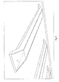
- Fig. 1 shows a perspective view of an embodiment of a lamp according to the invention.
- the luminaire may be a surface-mounted luminaire, for example a ceiling-mounted luminaire.
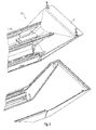
- Fig. 2 shows a sketch for the construction of the lamp in the manner of an exploded view.
- the luminaire comprises a support element 2, which may be designed in particular as a central support element of the luminaire and may be designed to hold further luminaire components, in particular as a device support of the luminaire.
- the support member 2 may for example consist of aluminum.
- the support element 2 is preferably a profile element which extends along a longitudinal axis L. As shown, the lamp as a whole may be elongated and also extend along the longitudinal axis L , so that the lamp - with respect to the longitudinal axis L - a first end portion 101 and a second end portion 102 has.
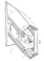
- Fig. 3 is a cut, perspective sketch around the first end portion 101 of the lamp shown.
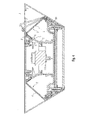
- Fig. 4 shows a cross section through the lamp, normal to the longitudinal axis L.
- an edge region 31 of a light emitting opening 3 is formed.
- the light emitting opening 3 can serve to emit a light to produce an indirect illumination.
- the lamp has a translucent cover 4, which is arranged covering the light emitting opening 3 such that through them an environment U of the lamp is separated from an interior I of the lamp.
- a light source of the lamp can be arranged, which serves to generate a light which is emitted through the light emitting opening 3 and through the cover 4 into the environment U.
- the light source may be an LED light source comprising a circuit board with LEDs arranged thereon.
- the cover 4 is supported by a latching connection 5 on the support element 2.
- the latching connection 5 has a covering latching element 6 formed on the cover 4, as well as a support element latching element 7 interacting therewith and formed on the support element 2.
- Fig. 5 shows an enlarged section Fig. 4 to the locking connection 5.
- the luminaire is designed such that for a non-destructive release of the latching connection 5, the cover latching element 6 must be moved along a direction R relative to the support element latching element 7, namely - as in Fig. 5 indicated - by a distance s. Accordingly, to produce the latching connection 5, the cover latching element 6 has to be moved counter to the direction R by the distance s .
- the cover 4 is made of plastic in order to achieve a corresponding mobility or flexibility of the cover 4.
- the latching connection 5 is formed in the interior I.
- the latching connection 5 is accordingly accessible from a region of the interior I , but not from the environment U , since the environment U is separated from the interior region I by the cover 4.
- Already hereby is a release of the latching connection 5 of the environment U from basically difficult at least.
- the luminaire is designed in such a way that no pressure and / or tension can be exerted on the luminaire by the surroundings U , by which the cover latching element 6 is moved in the direction R by the distance s relative to the support element latching element 7, without destroying a component of the luminaire.
- This makes it possible to achieve that by a manipulation of the lamp from the environment U from the latching connection 5 can not be practically solved without this case the lamp would be destroyed - not even with the aid of a commercial tool. It can be achieved in this way, in particular, that there is no possibility to open by loosening screws or the like nondestructively and to access live parts.
- a particularly simple embodiment is made possible when the cover detent element 6 is formed by a projection which extends in a first approximation against the direction R and the support element detent element 7 is formed by a recess into which the projection is arranged engaging.
- a particularly secure hold of the projection is given in the recess when the projection has at its free end an end portion 8 which is opposite to the direction R at least 45 °, preferably bent by at least 80 °.
- the support element detent element 7 has a corresponding small projection 71, which is designed such that it opposes a movement of the bent end portion 8 in the direction R.
- the latching connection 5 is preferably formed at a distance a from the edge region 31 of the light emitting opening 3, so that the accessibility to the latching connection 5 from the environment U is already made difficult thereby.
- the distance a is preferably more than 5 mm, more preferably more than 10 mm.
- the support element 2 is preferably formed by a support element profile element 20 which extends parallel to the longitudinal axis L.
- the cover 4 is preferably formed by a cover profile element 40, which also extends parallel to the longitudinal axis L. This allows a particularly simple and reliable design of the lamp allows.
- the cover profile element 40 is rotatably or pivotably mounted on a further edge region 32 of the light emission opening 3 opposite the edge region 31 with respect to the light emission opening 3, a particularly simple mounting of the cover 4 on the support element 2 is made possible.
- a guide groove 9 is preferably formed on the further edge region 32 into which the cover profile element 40 can initially be inserted on one side for assembly and subsequently pivoted into its intended position relative to the support element 2. This is in Fig. 5 with two further positions 4 ', 4''of the cover 4 indicated.
- the further edge region 32 can likewise be formed by the support element 2 or by a luminaire element, for example in the form of a frame element 90, which is connected to the support element 2 in such a manner that it is detached from the support element 2 destructively only from the interior I leaves. In this way, an unwanted access to the interior I can make it much more difficult.
- the interior I is viewed in a cross section normal to the longitudinal axis L except for a minimum gap in the region of the further edge region 32 whose width is preferably less than five millimeters, formed only by the support element 2.
- the guide groove 9 as such is formed in the frame member 90, wherein the frame member 90 is connected via a connection with the support member 2, which can be solved only from the interior I ago, for example in the form of a screw connection.
- the cover 4 is mounted in a further step, and then the interior I is closed or closed by producing the latching connection 5 the light emission opening 3 is covered.
- the cover 4 in the region of the first-mentioned edge region 31 may still have a PrinterSchenkel 41 which rests against the edge region 31 and which is located at a very small distance from the edge region 31, wherein the distance is for example less than 1 mm.
- a further lamp component 10 is arranged, which forms a still further edge region 33 of the light emitting opening 3.
- the design at the respective opposite end is preferably analog, so that - with respect to the longitudinal axis L - on both sides of the cover profile element 40 each have a further lighting component 10 is arranged and each of the two other lighting components 10 each have a further edge region 33 of the light emitting opening 3 forms.
- an overall annularly closed edge region of the light-emitting opening 3 is formed.
- Fig. 6 shows a perspective sketch of the end portion 101 without the cover. 4
- Each of the two further luminaire components 10 is advantageously connected to the support element 2 such that it can not be separated from the support element 2 without destruction.
- each of the two further luminaire components 10 with the support element 2 in each case via a rivet connection, in particular via a Be connected expansion rivet.
- a blind hole may be provided in the further lighting component 10 in which a corresponding expansion rivet engages.
- the two other lighting components 10 may be secured by means of correspondingly insoluble snap connections or by gluing or by screwing, wherein the screw heads are secured by casting or are.
- the two further luminaire components 10 may be front reflector covers, for example.
- the two other lighting components 10 may for example consist of aluminum. It may be aluminum die castings.
- the two other lighting components 10 may be integrally formed with the support element 2 or formed as parts of the support element 2.
- the luminaire may have, on an opposite side with respect to the longitudinal axis L, a further light-emitting opening 3 ', which is covered in a similar manner with a further cover 4'.
- the cover 4 can easily snap on the support member 2, but can not be dismantled without destruction. As a result, a particularly reliable contact protection for the lamp is formed.
Landscapes
- Engineering & Computer Science (AREA)
- General Engineering & Computer Science (AREA)
- Non-Portable Lighting Devices Or Systems Thereof (AREA)
- Securing Globes, Refractors, Reflectors Or The Like (AREA)
Abstract
Description
- Die Erfindung betrifft eine Leuchte mit einem Stützelement, durch das ein Randbereich einer Lichtabgabeöffnung gebildet ist, sowie mit einer, durch eine Rastverbindung an dem Stützelement gehalterte, lichtdurchlässige Abdeckung, die die Lichtabgabeöffnung abdeckend angeordnet ist.
- Bei einer derartigen Leuchte besteht im Allgemeinen die Möglichkeit, dass durch eine Manipulation von außen die Abdeckung abgenommen wird und so ein Zugang zu einem Innenraum der Leuchte eröffnet wird. Dies ist in der Regel jedoch unerwünscht, weil sich in dem Innenraum üblicherweise ein stromführendes Bauteil befindet und auf diese Weise ein Gefährdungspotenzial für einen Nutzer der Leuchte gegeben ist.
- Bei dem stromführenden Bauteil kann es sich beispielweise um eine LED-Lichtquelle (LED: lichtemittierende Diode) mit einer LED-Platine und darauf angeordneten LEDs handeln. LED-Platinen werden üblicherweise mit einer Spannung von mehr als 60 V betrieben.
- Insbesondere besteht dabei die Gefahr, dass der Nutzer der Leuchte versucht, bei Ausfall des Leuchtmittels, also beispielsweise der LED-Lichtquelle, das Leuchtmittel auszutauschen, ohne die Leuchte zuvor von der Spannungsquelle zu trennen.
- Es gibt auch entsprechende Vorschriften mit Bezug auf einen Schutz vor Berührung, gemäß denen ein zerstörungsfreies Öffnen des Innenraums mit handelsüblichem Werkzeug nicht möglich sein darf.
- Der Erfindung liegt die Aufgabe zugrunde, eine entsprechende verbesserte Leuchte anzugeben. Insbesondere soll die Leuchte bei einfacher Herstellung besonders sicher sein bzw. einen besonders guten Schutz vor Berührung eines Innenraums der Leuchte bieten.
- Diese Aufgabe wird gemäß der Erfindung mit dem in dem unabhängigen Anspruch genannten Gegenstand gelöst. Besondere Ausführungsarten der Erfindung sind in den abhängigen Ansprüchen angegeben.
- Gemäß der Erfindung ist eine Leuchte vorgesehen, die ein Stützelement aufweist, durch das ein Randbereich einer Lichtabgabeöffnung gebildet ist, sowie eine lichtdurchlässige Abdeckung, die die Lichtabgabeöffnung derart abdeckend angeordnet ist, dass durch sie eine Umgebung der Leuchte von einem Innenraum der Leuchte getrennt ist. Die Abdeckung ist dabei durch eine Rastverbindung an dem Stützelement gehaltert und die Rastverbindung weist zur Halterung der Abdeckung an dem Stützelement ein, an der Abdeckung ausgebildetes Abdeckungs-Rastelement und ein damit wechselwirkendes, am Stützelement ausgebildetes Stützelement-Rastelement auf. Die Gestaltung der Leuchte ist dabei derart, dass für ein zerstörungsfreies Lösen der Rastverbindung das Abdeckungs-Rastelement längs einer Richtung um eine Strecke gegenüber dem Stützelement-Rastelement bewegt werden muss. Die Rastverbindung ist in dem Innenraum ausgebildet und die Leuchte ist derart gestaltet, dass von der Umgebung aus kein Druck und/oder Zug auf die Leuchte ausgeübt werden kann, durch den das Abdeckungs-Rastelement in die Richtung um die Strecke gegenüber dem Stützelement-Rastelement bewegt wird, ohne ein Bauteil der Leuchte zu zerstören.
- Auf diese Weise lässt sich erzielen, dass durch äußere Manipulation die Abdeckung praktisch nicht vom Gehäuse gelöst werden kann, ohne dabei die Leuchte zu zerstören.
- Vorzugsweise ist die Leuchte derart gestaltet, dass ein Zugang zu dem Innenraum nicht möglich ist, ohne ein Bauteil der Leuchte zu zerstören. Auf diese Weise ist die Gefahr, dass ein Nutzer der Leuchte durch Zugang zu dem Innenraum einen Stromschlag erhält oder die Lichtquelle beschädigt wird, signifikant verringert.
- Herstellungstechnisch vorteilhaft bestehen das Stützelement aus Aluminium und/oder die Abdeckung aus Kunststoff.
- Vorzugsweise ist das Abdeckungs-Rastelement durch einen Vorsprung gebildet, der sich in erster Näherung entgegen der Richtung erstreckt und das Stützelement-Rastelement durch eine Ausnehmung gebildet, in die der Vorsprung eingreifend angeordnet ist. Hierdurch ist eine zuverlässige Halterung bei einfacher Herstellungsmöglichkeit gegeben. Ein besonders guter Halt des Vorsprungs in der Ausnehmung ist dabei ermöglicht, wenn der Vorsprung einen Endbereich aufweist, der gegenüber der Richtung um mindestens 45°, vorzugsweise um mindestens 80° abgebogen ist.
- Vorzugsweise ist die Rastverbindung in einem Abstand von dem Randbereich der Lichtabgabeöffnung ausgebildet, der mehr als 5 mm, besonders bevorzugt mehr als 10 mm beträgt. Hierdurch ist die Zugänglichkeit und damit die Manipulationsmöglichkeit der Rastverbindung weiterhin erschwert.
- Vorzugsweise ist das Stützelement durch ein Stützelement-Profilelement gebildet, das sich parallel zu einer Längsachse erstreckt, wobei die Abdeckung durch ein Abdeckungs-Profilelement gebildet ist, das sich ebenfalls parallel zu der Längsachse erstreckt. Hierdurch ist eine besonders einfache Herstellung ermöglicht.
- Dabei ist die Leuchte weiterhin vorzugsweise derart gestaltet, dass das Abdeckungs-Profilelement an einem, mit Bezug auf die Lichtabgabeöffnung dem Randbereich gegenüberliegenden weiteren Randbereich der Lichtabgabeöffnung drehbar bzw. schwenkbar gelagert. Hierdurch lässt sich erzielen, dass die Abdeckung besonders leicht an dem Stützelement montiert werden kann. Vorzugsweise ist dabei der der weitere Randbereich durch das Stützelement gebildet oder durch ein Leuchtenelement, beispielsweise ein Rahmenelement, das mit dem Stützelement derart verbunden ist, dass es sich lediglich von dem Innenraum aus zerstörungsfrei von dem Stützelement lösen lässt. Auf diese Weise lässt sich ein ungewollter Zugang zu dem Innenraum deutlich erschweren.
- Dabei weist der weitere Randbereich vorteilhaft eine Führungsnut auf, in die das Abdeckungs-Profilelement eingelegt ist.
- Weiterhin vorzugsweise ist mit Bezug auf die Längsachse L an beiden Endbereichen des Abdeckungs-Profilelements jeweils ein weiteres Leuchtenbauteil angeordnet, das jeweils einen noch weiteren Randbereich der Lichtabgabeöffnung bildet. Hierdurch lässt sich herstellungstechnisch vorteilhaft erzielen, dass die Lichtabgabeöffnung allseits geschlossen ist, so dass die Zugänglichkeit zu der Rastverbindung weiterhin erschwert ist. Vorzugsweise ist dabei jedes der beiden weiteren Leuchtenbauteile mit dem Stützelement derart verbunden ist, dass es nicht ohne Zerstörung von dem Stützelement getrennt werden kann. Vorteilhaft ist hierzu jedes der beiden weiteren Leuchtenbauteile mit dem Stützelement jeweils über eine Nietverbindung, insbesondere über eine Spreiznietverbindung verbunden.
- Die Erfindung wird im Folgenden anhand eines Ausführungsbeispiels und mit Bezug auf die Zeichnungen näher erläutert. Es zeigen:
- Fig. 1
- eine perspektivische Ansicht einer erfindungsgemäßen Leuchte,
- Fig. 2
- eine Skizze zum Aufbau der Leuchte nach Art einer Explosionsdarstellung,
- Fig. 3
- eine perspektivische Skizze eines Endbereichs der Leuchte,
- Fig. 4
- einen Querschnitt durch die Leuchte,
- Fig. 5
- einen vergrößerten Ausschnitt aus
Fig. 4 und - Fig. 6
- eine perspektivische Skizze um einen Endbereich der Leuchte nach Art einer Explosionsdarstellung.
-
Fig. 1 zeigt eine perspektivische Ansicht eines Ausführungsbeispiels einer erfindungsgemäßen Leuchte. Wie exemplarisch gezeigt, kann es sich bei der Leuchte um eine Anbauleuchte, beispielsweise eine Deckenanbauleuchte handeln. -
Fig. 2 zeigt eine Skizze zum Aufbau der Leuchte nach Art einer Explosionsdarstellung. Die Leuchte umfasst ein Stützelement 2, das insbesondere als zentrales Stützelement der Leuchte gestaltet sein kann und zur Halterung von weiteren Leuchtenbauteilen ausgestaltet sein kann, insbesondere als Geräteträger der Leuchte. Das Stützelement 2 kann beispielsweise aus Aluminium bestehen. - Bei dem Stützelement 2 handelt es sich vorzugsweise um ein Profilelement, das sich längs einer Längsachse L erstreckt. Wie gezeigt, kann die Leuchte insgesamt länglich sein und sich ebenfalls längs der Längsachse L erstrecken, so dass die Leuchte - mit Bezug auf die Längsachse L - einen ersten Endbereich 101 und einen zweiten Endbereich 102 aufweist.
- In
Fig. 3 ist eine geschnittene, perspektivische Skizze um den ersten Endbereich 101 der Leuchte gezeigt.Fig. 4 zeigt einen Querschnitt durch die Leuchte, normal zu der Längsachse L. - Durch das Stützelement 2 ist ein Randbereich 31 einer Lichtabgabeöffnung 3 gebildet. Wie im gezeigten Beispiel der Fall, kann die Lichtabgabeöffnung 3 zur Abgabe eines Lichts zur Erzeugung einer indirekten Beleuchtung dienen.
- Weiterhin weist die Leuchte eine lichtdurchlässige Abdeckung 4 auf, die die Lichtabgabeöffnung 3 derart abdeckend angeordnet ist, dass durch sie eine Umgebung U der Leuchte von einem Innenraum I der Leuchte getrennt ist. In dem Innenraum I kann eine Lichtquelle der Leuchte angeordnet sein, die zur Erzeugung eines Lichts dient, das durch die Lichtabgabeöffnung 3 bzw. durch die Abdeckung 4 hindurch in die Umgebung U abgestrahlt wird. Bei der Lichtquelle kann es sich beispielsweise um eine LED-Lichtquelle handeln, die eine Platine mit darauf angeordneten LEDs umfasst.
- Die Abdeckung 4 ist dabei durch eine Rastverbindung 5 an dem Stützelement 2 gehaltert. Zur Halterung der Abdeckung 4 an dem Stützelement 2 weist die Rastverbindung 5 ein, an der Abdeckung 4 ausgebildetes Abdeckungs-Rastelement 6 auf, sowie ein hiermit wechselwirkendes, am Stützelement 2 ausgebildetes Stützelement-Rastelement 7.
Fig. 5 zeigt einen vergrößerten Ausschnitt ausFig. 4 um die Rastverbindung 5. - Die Leuchte ist derart gestaltet, dass für ein zerstörungsfreies Lösen der Rastverbindung 5 das Abdeckungs-Rastelement 6 längs einer Richtung R gegenüber dem Stützelement-Rastelement 7 bewegt werden muss, und zwar - wie in
Fig. 5 angedeutet - um eine Strecke s. Dementsprechend muss zur Herstellung der Rastverbindung 5 das Abdeckungs-Rastelement 6 entgegen der Richtung R um die Strecke s bewegt werden. Bevorzugt besteht die Abdeckung 4 aus Kunststoff, um eine entsprechende Beweglichkeit bzw. Flexibilität der Abdeckung 4 zu erzielen. - Wie beispielhaft gezeigt, ist die Rastverbindung 5 in dem Innenraum I ausgebildet. Die Rastverbindung 5 ist dementsprechend von einem Bereich des Innenraums I aus zugänglich, jedoch nicht von der Umgebung U aus, da die Umgebung U von dem Innenbereich I durch die Abdeckung 4 getrennt ist. Bereits hierdurch ist ein Lösen der Rastverbindung 5 von der Umgebung U aus grundsätzlich zumindest erschwert.
- Weiterhin ist die Leuchte derart gestaltet, dass von der Umgebung U aus kein Druck und/oder Zug auf die Leuchte ausgeübt werden kann, durch den das Abdeckungs-Rastelement 6 in die Richtung R um die Strecke s gegenüber dem Stützelement-Rastelement 7 bewegt wird, ohne ein Bauteil der Leuchte zu zerstören. Hierdurch lässt sich erzielen, dass durch eine Manipulation der Leuchte von der Umgebung U aus die Rastverbindung 5 praktisch nicht gelöst werden kann, ohne dass hierbei die Leuchte zerstört würde - auch nicht unter Zuhilfenahme eines handelsüblichen Werkzeugs. Es lässt sich auf diese Weise insbesondere erzielen, dass keine Möglichkeit besteht, durch Lösen von Schrauben oder dergleichen die Leuchte zerstörungsfrei zu öffnen und auf spannungsführende Teile zu greifen.
- Eine besonders einfache Ausgestaltung ist ermöglicht, wenn das Abdeckungs-Rastelement 6 durch einen Vorsprung gebildet ist, der sich in erster Näherung entgegen der Richtung R erstreckt und das Stützelement-Rastelement 7 durch eine Ausnehmung gebildet ist, in die der Vorsprung eingreifend angeordnet ist. Dabei ist ein besonders sicherer Halt des Vorsprungs in der Ausnehmung gegeben, wenn der Vorsprung an seinem freien Ende einen Endbereich 8 aufweist, der gegenüber der Richtung R um mindestens 45°, vorzugsweise um mindestens 80° abgebogen ist. Besonders bevorzugt weist das Stützelement-Rastelement 7 einen hierzu korrespondierenden kleinen Fortsatz 71 auf, der derart ausgebildet ist, dass er einer Bewegung des abgebogenen Endbereichs 8 in Richtung R entgegensteht.
- Wie weiterhin in
Fig. 5 angedeutet, ist die Rastverbindung 5 vorzugsweise in einem Abstand a von dem Randbereich 31 der Lichtabgabeöffnung 3 ausgebildet, so dass die Zugänglichkeit zu der Rastverbindung 5 von der Umgebung U aus bereits hierdurch erschwert ist. Vorzugsweise beträgt der Abstand a hierzu mehr als 5 mm, besonders bevorzugt mehr als 10 mm. - Wie oben bereits erwähnt, ist das Stützelement 2 vorzugsweise durch ein Stützelement-Profilelement 20 gebildet, das sich parallel zu der Längsachse L erstreckt. Die Abdeckung 4 ist vorzugsweise durch ein Abdeckungs-Profilelement 40 gebildet, das sich ebenfalls parallel zu der Längsachse L erstreckt. Hierdurch ist eine besonders einfache und zuverlässige Ausführung der Leuchte ermöglicht.
- Wenn, wie in
Fig. 5 beispielhaft angedeutet, das Abdeckungs-Profilelement 40 an einem, mit Bezug auf die Lichtabgabeöffnung 3 dem Randbereich 31 gegenüberliegenden, weiteren Randbereich 32 der Lichtabgabeöffnung 3 drehbar bzw. schwenkbar gelagert ist, ist eine besonders einfache Montage der Abdeckung 4 an dem Stützelement 2 ermöglicht. - Vorzugsweise ist an dem weiteren Randbereich 32 hierzu eine Führungsnut 9 ausgebildet, in die das Abdeckungs-Profilelement 40 zur Montage zunächst einseitig eingelegt und anschließend in seine vorgesehene Position gegenüber dem Stützelement 2 geschwenkt werden kann. Dies ist in
Fig. 5 mit zwei weiteren Stellungen 4', 4'' der Abdeckung 4 angedeutet. - Der weitere Randbereich 32 kann dabei ebenfalls durch das Stützelement 2 gebildet sein bzw. durch ein Leuchtenelement, beispielsweise in Form eines Rahmenelements 90, das mit dem Stützelement 2 derart verbunden ist, dass es sich lediglich von dem Innenraum I aus zerstörungsfrei von dem Stützelement 2 lösen lässt. Auf diese Weise lässt sich ein ungewollter Zugang zu dem Innenraum I deutlich erschweren.
- Wie aus
Fig. 5 hervorgeht, ist im gezeigten Beispiel der Innenraum I in einem Querschnitt normal zu der Längsachse L betrachtet bis auf einen minimalen Spalt im Bereich des weiteren Randbereichs 32, dessen Breite vorzugsweise kleiner als fünf Millimeter ist, lediglich durch das Stützelement 2 gebildet. Die Führungsnut 9 als solche ist in dem Rahmenelement 90 ausgebildet, wobei das Rahmenelement 90 über eine Verbindung mit dem Stützelement 2 verbunden ist, die sich lediglich vom Innenraum I her lösen lässt, beispielsweise in Form einer Schraubverbindung. Zum Zusammenbau der Leuchte kann daher vorgesehen sein, dass zunächst - bei noch nicht montierter Abdeckung 4 - das Rahmenelement 90 mit dem Stützelement 2 verschraubt wird, in einem weiteren Schritt die Abdeckung 4 montiert wird und anschließend durch Herstellen der Rastverbindung 5 der Innenraum I verschlossen bzw. die Lichtabgabeöffnung 3 abgedeckt wird. - Um die Zugänglichkeit zu der Rastverbindung 5 noch weiter zu erschweren, kann die Abdeckung 4 im Bereich des zuerst genannten Randbereichs 31 noch einen AnlageSchenkel 41 aufweisen, der an dem Randbereich 31 anliegt bzw. der sich in sehr geringem Abstand gegenüber dem Randbereich 31 befindet, wobei der Abstand beispielsweise weniger als 1 mm beträgt.
- Wie in
Fig. 3 angedeutet, ist an dem, zu dem ersten Endbereich 101 der Leuchte korrespondierenden Endbereich des Abdeckungs-Profilelements 40 ein weiteres Leuchtenbauteil 10 angeordnet, das einen noch weiteren Randbereich 33 der Lichtabgabeöffnung 3 bildet. Wie inFig. 2 gezeigt, ist die Gestaltung an dem betreffenden gegenüberliegenden Ende vorzugsweise analog, so dass - mit Bezug auf die Längsachse L - zu beiden Seiten des Abdeckungs-Profilelements 40 jeweils ein weiteres Leuchtenbauteil 10 angeordnet ist und jedes der beiden weiteren Leuchtenbauteile 10 einen jeweils noch weiteren Randbereich 33 der Lichtabgabeöffnung 3 bildet. Vorzugsweise ist durch den zuerst genannten Randbereich 31, den weiteren Randbereich 32 und die beiden noch weiteren Randbereiche 33 ein insgesamt ringförmig geschlossener Randbereich der Lichtabgabeöffnung 3 gebildet. -
Fig. 6 zeigt eine perspektivische Skizze des Endbereichs 101 ohne die Abdeckung 4. - Jedes der beiden weiteren Leuchtenbauteile 10 ist vorteilhaft mit dem Stützelement 2 derart verbunden, dass es nicht ohne Zerstörung von dem Stützelement 2 getrennt werden kann. Beispielsweise kann hierzu jedes der beiden weiteren Leuchtenbauteile 10 mit dem Stützelement 2 jeweils über eine Nietverbindung, insbesondere über eine Spreiznietverbindung verbunden sein. Beispielsweise kann in dem weiteren Leuchtenbauteil 10 ein Sackloch vorgesehen sein, in dem ein entsprechender Spreizniet eingreift.
- Eine derartige Verbindung lässt sich zwar beispielsweise durch ein Aufbohren lösen, dies ist aber zwangsläufig nur durch Zerstören der Leuchte möglich.
- Alternativ können die beiden weiteren Leuchtenbauteile 10 mittels entsprechend unlösbaren Schnappverbindungen befestigt sein oder durch Kleben oder durch Verschrauben, wobei durch Vergießen die Schraubenköpfe gesichert werden bzw. sind.
- Bei den beiden weiteren Leuchtenbauteilen 10 kann es sich beispielsweise um stirnseitige Reflektorabdeckungen handeln. Die beiden weiteren Leuchtenbauteile 10 können beispielsweise aus Aluminium bestehen. Es kann sich um Aluminium-Druckgussteile handeln.
- Gemäß einer (in den Figuren nicht gezeigten) Variante können die beiden weiteren Leuchtenbauteile 10 einstückig mit dem Stützelement 2 ausgebildet sein bzw. als Teile des Stützelements 2 ausgebildet sein.
- Wie im gezeigten Beispiel der Fall, kann die Leuchte auf einer, mit Bezug auf die Längsachse L gegenüberliegenden Seite eine weitere Lichtabgabeöffnung 3' aufweisen, die auf analoge Weise mit einer weiteren Abdeckung 4' abgedeckt ist.
- Durch die beschriebene Gestaltung der Leuchte wird erzielt, dass sich die Abdeckung 4 leicht auf das Stützelement 2 aufschnappen lässt, jedoch ohne Zerstörung nicht demontiert werden kann. Hierdurch ist ein besonders zuverlässiger Berührschutz für die Leuchte gebildet.
Claims (13)
- Leuchte, aufweisend- ein Stützelement (2), durch das ein Randbereich (31) einer Lichtabgabeöffnung (3) gebildet ist und- eine lichtdurchlässige Abdeckung (4), die die Lichtabgabeöffnung (3) derart abdeckend angeordnet ist, dass durch sie eine Umgebung (U) der Leuchte von einem Innenraum (I) der Leuchte getrennt ist,
wobei die Abdeckung (4) durch eine Rastverbindung (5) an dem Stützelement (2) gehaltert ist und die Rastverbindung (5) zur Halterung der Abdeckung (4) an dem Stützelement (2) ein, an der Abdeckung (4) ausgebildetes Abdeckungs-Rastelement (6) und ein damit wechselwirkendes, am Stützelement (2) ausgebildetes Stützelement-Rastelement (7) aufweist,
wobei für ein zerstörungsfreies Lösen der Rastverbindung (5) das Abdeckungs-Rastelement (6) längs einer Richtung (R) um eine Strecke (s) gegenüber dem Stützelement-Rastelement (7) bewegt werden muss,
dadurch gekennzeichnet,
dass die Rastverbindung (5) in dem Innenraum (I) ausgebildet ist und die Leuchte derart gestaltet ist, dass von der Umgebung (U) aus kein Druck und/oder Zug auf die Leuchte ausgeübt werden kann, durch den das Abdeckungs-Rastelement (6) in die Richtung (R) um die Strecke (s) gegenüber dem Stützelement-Rastelement (7) bewegt wird, ohne ein Bauteil der Leuchte zu zerstören. - Leuchte nach Anspruch 1,
die derart gestaltet ist, dass ein Zugang zu dem Innenraum (I) nicht möglich ist, ohne ein Bauteil der Leuchte zu zerstören. - Leuchte nach Anspruch 1 oder 2,
bei der das Stützelement (2) aus Aluminium besteht und/oder die Abdeckung (4) aus Kunststoff. - Leuchte nach einem der vorhergehenden Ansprüche,
bei der das Abdeckungs-Rastelement (6) durch einen Vorsprung gebildet ist, der sich in erster Näherung entgegen der Richtung (R) erstreckt und das Stützelement-Rastelement (7) durch eine Ausnehmung gebildet ist, in die der Vorsprung eingreifend angeordnet ist. - Leuchte nach Anspruch 4,
bei der der Vorsprung an seinem freien Ende einen Endbereich (8) aufweist, der gegenüber der Richtung (R) um mindestens 45°, vorzugsweise um mindestens 80° abgebogen ist. - Leuchte nach einem der vorhergehenden Ansprüche,
bei der die Rastverbindung (5) in einem Abstand (a) von dem Randbereich (31) der Lichtabgabeöffnung (3) ausgebildet ist, der mehr als 5 mm, besonders bevorzugt mehr als 10 mm beträgt. - Leuchte nach einem der vorhergehenden Ansprüche,
bei der das Stützelement (2) durch ein Stützelement-Profilelement (20) gebildet ist, das sich parallel zu einer Längsachse (L) erstreckt und die Abdeckung (4) durch ein Abdeckungs-Profilelement (40) gebildet ist, das sich ebenfalls parallel zu der Längsachse (L) erstreckt. - Leuchte nach Anspruch 7,
die derart gestaltet ist, dass das Abdeckungs-Profilelement (40) an einem, mit Bezug auf die Lichtabgabeöffnung (3) dem Randbereich (31) gegenüberliegenden weiteren Randbereich (32) der Lichtabgabeöffnung (3) drehbar oder schwenkbar gelagert ist. - Leuchte nach Anspruch 8,
bei der der weitere Randbereich (32) durch das Stützelement (2) gebildet ist oder durch ein Leuchtenelement, beispielsweise ein Rahmenelement (90), das mit dem Stützelement (2) derart verbunden ist, dass es sich lediglich von dem Innenraum (I) aus zerstörungsfrei von dem Stützelement (2) lösen lässt. - Leuchte nach Anspruch 8 oder 9,
bei der der weitere Randbereich (32) eine Führungsnut (9) aufweist und das Abdeckungs-Profilelement (40) in die Führungsnut (9) eingelegt ist. - Leuchte nach einem der Ansprüche 7 bis 10,
bei der mit Bezug auf die Längsachse (L) an beiden Endbereichen des Abdeckungs-Profilelements (40) jeweils ein weiteres Leuchtenbauteil (10) angeordnet ist und jedes der beiden weiteren Leuchtenbauteile (10) einen jeweils noch weiteren Randbereich (33) der Lichtabgabeöffnung (3) bildet. - Leuchte nach Anspruch 11,
bei der jedes der beiden weiteren Leuchtenbauteile (10) mit dem Stützelement (2) derart verbunden ist, dass es nicht ohne Zerstörung von dem Stützelement (2) getrennt werden kann. - Leuchte nach Anspruch 12,
bei der jedes der beiden weiteren Leuchtenbauteile (10) mit dem Stützelement (2) jeweils über eine Nietverbindung, insbesondere über eine Spreiznietverbindung verbunden ist.
Applications Claiming Priority (1)
| Application Number | Priority Date | Filing Date | Title |
|---|---|---|---|
| DE202012103667.3U DE202012103667U1 (de) | 2012-09-25 | 2012-09-25 | Leuchte mit Berührschutz |
Publications (3)
| Publication Number | Publication Date |
|---|---|
| EP2711622A2 true EP2711622A2 (de) | 2014-03-26 |
| EP2711622A3 EP2711622A3 (de) | 2014-11-19 |
| EP2711622B1 EP2711622B1 (de) | 2016-04-27 |
Family
ID=49237075
Family Applications (1)
| Application Number | Title | Priority Date | Filing Date |
|---|---|---|---|
| EP13185744.3A Not-in-force EP2711622B1 (de) | 2012-09-25 | 2013-09-24 | Leuchte mit Berührschutz |
Country Status (2)
| Country | Link |
|---|---|
| EP (1) | EP2711622B1 (de) |
| DE (1) | DE202012103667U1 (de) |
Cited By (1)
| Publication number | Priority date | Publication date | Assignee | Title |
|---|---|---|---|---|
| WO2024140875A1 (zh) * | 2022-12-28 | 2024-07-04 | 苏州欧普照明有限公司 | 照明装置 |
Family Cites Families (13)
| Publication number | Priority date | Publication date | Assignee | Title |
|---|---|---|---|---|
| US3210875A (en) * | 1963-02-05 | 1965-10-12 | Patent License Corp | Lighting fixture |
| US4338653A (en) * | 1980-09-24 | 1982-07-06 | Louis Marrero | Versatile fluorescent lighting fixture |
| US4625267A (en) * | 1984-09-28 | 1986-11-25 | Transmatic, Incorporated | Strip lighting fixture for mass transit vehicles |
| DE3643075A1 (de) * | 1985-12-27 | 1987-08-06 | Hans Theodor Roettger | Vorhangbeleuchtung |
| JP4034514B2 (ja) * | 1997-09-01 | 2008-01-16 | ブランカ アガベコフ | 照明器具 |
| DE20205734U1 (de) * | 2002-04-12 | 2002-06-27 | Herbert Waldmann GmbH & Co., 78056 Villingen-Schwenningen | Leuchte |
| ES2557159T3 (es) * | 2004-12-23 | 2016-01-22 | Nualight Limited | Iluminación de vitrina de exposición |
| EP1734300B2 (de) * | 2005-06-13 | 2013-11-20 | Hartmut S. Engel | Innenraumleuchte |
| DE202006005920U1 (de) * | 2006-04-10 | 2006-06-22 | Semperlux Ag - Lichttechnische Werke - | Beleuchtungsanordnung mit Entblendung |
| DE102006018255A1 (de) * | 2006-04-18 | 2007-10-25 | Zumtobel Lighting Gmbh | Leuchte, insbesondere Hängleuchte, mit einem ersten und einem zweiten Licht-Abstrahlbereich |
| DE102009007308B4 (de) * | 2009-02-03 | 2014-11-20 | Herbert Waldmann Gmbh & Co Kg | Anbau- bzw. Wandleuchte |
| DE102010016714A1 (de) * | 2010-02-09 | 2011-08-11 | DEWINCI GmbH, 46483 | LED-Stablampe |
| KR101349841B1 (ko) * | 2010-06-24 | 2014-01-09 | 엘지전자 주식회사 | Led 조명기구 |
-
2012
- 2012-09-25 DE DE202012103667.3U patent/DE202012103667U1/de not_active Expired - Lifetime
-
2013
- 2013-09-24 EP EP13185744.3A patent/EP2711622B1/de not_active Not-in-force
Non-Patent Citations (1)
| Title |
|---|
| None |
Cited By (1)
| Publication number | Priority date | Publication date | Assignee | Title |
|---|---|---|---|---|
| WO2024140875A1 (zh) * | 2022-12-28 | 2024-07-04 | 苏州欧普照明有限公司 | 照明装置 |
Also Published As
| Publication number | Publication date |
|---|---|
| EP2711622A3 (de) | 2014-11-19 |
| DE202012103667U1 (de) | 2014-01-07 |
| EP2711622B1 (de) | 2016-04-27 |
Similar Documents
| Publication | Publication Date | Title |
|---|---|---|
| EP2138873B1 (de) | Leuchte mit wenigstens einer lichtdurchlässigen Abdeckung | |
| EP2394094B1 (de) | Anbau- bzw. wandleuchte | |
| EP3006816A1 (de) | Längliche led-leuchte mit optischem element | |
| EP3114400B1 (de) | Leuchte bzw. beleuchtungsanordnung mit länglichem trägerelement und lösbar befestigbarem leuchtmodul | |
| EP2622262B1 (de) | Leuchtmodulanordnung mit einer led auf einer platine | |
| EP2796770A1 (de) | Leuchte mit einer Lichterzeugungseinheit und einem Rahmenelement | |
| DE102019109676A1 (de) | Haltefeder für Leuchte | |
| EP2873913A1 (de) | LED-Leuchte | |
| EP2711622B1 (de) | Leuchte mit Berührschutz | |
| EP2994694B1 (de) | Plattenförmiges reflektorelement für led-platine | |
| EP3343102A1 (de) | Lichtleiter-element, anordnung zur lichtabgabe sowie leuchte | |
| DE202011002611U1 (de) | Lampenfassung mit transparentem Teil mit integrierter Linse | |
| EP2816543B1 (de) | Befestigungsprofil und Leuchtvorrichtung | |
| WO2017054023A1 (de) | Längliche leucht-anordnung mit sensor | |
| EP2910843B1 (de) | Beleuchtungseinheit | |
| EP2453168B1 (de) | Schutzelement für eine Platine in einer Leuchte | |
| DE202011051015U1 (de) | Einbauleuchte | |
| EP2833050B1 (de) | Pendelleuchte mit einer Lichtquelle zur Erzeugung einer indirekten Beleuchtung | |
| DE202012009313U1 (de) | Schaltschrankleuchte | |
| EP3336419A1 (de) | Leuchte mit positionierungselement zum halten von platine und optischen bauteilen | |
| EP2518399B1 (de) | Leuchte | |
| EP2994690B1 (de) | Leuchte mit gehäuse mit mehreren lichtabstrahlöffnungen | |
| CH709411B1 (de) | Leuchtelement mit OLED. | |
| DE102013112924A1 (de) | Steuergehäuse | |
| EP2910846A1 (de) | Beleuchtungseinheit und Trägerkörper für die Beleuchtungseinheit |
Legal Events
| Date | Code | Title | Description |
|---|---|---|---|
| PUAI | Public reference made under article 153(3) epc to a published international application that has entered the european phase |
Free format text: ORIGINAL CODE: 0009012 |
|
| AK | Designated contracting states |
Kind code of ref document: A2 Designated state(s): AL AT BE BG CH CY CZ DE DK EE ES FI FR GB GR HR HU IE IS IT LI LT LU LV MC MK MT NL NO PL PT RO RS SE SI SK SM TR |
|
| AX | Request for extension of the european patent |
Extension state: BA ME |
|
| PUAL | Search report despatched |
Free format text: ORIGINAL CODE: 0009013 |
|
| AK | Designated contracting states |
Kind code of ref document: A3 Designated state(s): AL AT BE BG CH CY CZ DE DK EE ES FI FR GB GR HR HU IE IS IT LI LT LU LV MC MK MT NL NO PL PT RO RS SE SI SK SM TR |
|
| AX | Request for extension of the european patent |
Extension state: BA ME |
|
| RIC1 | Information provided on ipc code assigned before grant |
Ipc: F21S 8/04 20060101ALN20141014BHEP Ipc: F21V 3/00 20060101ALI20141014BHEP Ipc: F21V 15/00 20060101ALI20141014BHEP Ipc: F21V 3/04 20060101ALN20141014BHEP Ipc: F21Y 101/02 20060101ALN20141014BHEP Ipc: F21V 17/16 20060101AFI20141014BHEP Ipc: F21V 15/01 20060101ALI20141014BHEP Ipc: F21V 21/02 20060101ALN20141014BHEP Ipc: F21V 17/10 20060101ALI20141014BHEP |
|
| 17P | Request for examination filed |
Effective date: 20150413 |
|
| RBV | Designated contracting states (corrected) |
Designated state(s): AL AT BE BG CH CY CZ DE DK EE ES FI FR GB GR HR HU IE IS IT LI LT LU LV MC MK MT NL NO PL PT RO RS SE SI SK SM TR |
|
| GRAP | Despatch of communication of intention to grant a patent |
Free format text: ORIGINAL CODE: EPIDOSNIGR1 |
|
| RIC1 | Information provided on ipc code assigned before grant |
Ipc: F21V 3/00 20150101ALI20151103BHEP Ipc: F21V 3/04 20060101ALN20151103BHEP Ipc: F21Y 101/02 20060101ALN20151103BHEP Ipc: F21V 15/00 20150101ALI20151103BHEP Ipc: F21S 8/04 20060101ALN20151103BHEP Ipc: F21V 17/16 20060101AFI20151103BHEP Ipc: F21V 21/02 20060101ALN20151103BHEP Ipc: F21V 15/01 20060101ALI20151103BHEP Ipc: F21V 17/10 20060101ALI20151103BHEP |
|
| INTG | Intention to grant announced |
Effective date: 20151125 |
|
| GRAS | Grant fee paid |
Free format text: ORIGINAL CODE: EPIDOSNIGR3 |
|
| GRAA | (expected) grant |
Free format text: ORIGINAL CODE: 0009210 |
|
| RIC1 | Information provided on ipc code assigned before grant |
Ipc: F21V 21/02 20060101ALN20160309BHEP Ipc: F21V 3/04 20060101ALN20160309BHEP Ipc: F21Y 115/10 20160101ALN20160309BHEP Ipc: F21S 8/04 20060101ALN20160309BHEP Ipc: F21V 17/10 20060101ALI20160309BHEP Ipc: F21V 15/01 20060101ALI20160309BHEP Ipc: F21V 15/00 20150101ALI20160309BHEP Ipc: F21V 17/16 20060101AFI20160309BHEP Ipc: F21V 3/00 20150101ALI20160309BHEP |
|
| AK | Designated contracting states |
Kind code of ref document: B1 Designated state(s): AL AT BE BG CH CY CZ DE DK EE ES FI FR GB GR HR HU IE IS IT LI LT LU LV MC MK MT NL NO PL PT RO RS SE SI SK SM TR |
|
| REG | Reference to a national code |
Ref country code: GB Ref legal event code: FG4D Free format text: NOT ENGLISH |
|
| REG | Reference to a national code |
Ref country code: CH Ref legal event code: EP |
|
| REG | Reference to a national code |
Ref country code: AT Ref legal event code: REF Ref document number: 795232 Country of ref document: AT Kind code of ref document: T Effective date: 20160515 |
|
| REG | Reference to a national code |
Ref country code: IE Ref legal event code: FG4D Free format text: LANGUAGE OF EP DOCUMENT: GERMAN |
|
| REG | Reference to a national code |
Ref country code: CH Ref legal event code: NV Representative=s name: WEINMANN ZIMMERLI, CH |
|
| REG | Reference to a national code |
Ref country code: DE Ref legal event code: R096 Ref document number: 502013002753 Country of ref document: DE |
|
| REG | Reference to a national code |
Ref country code: LT Ref legal event code: MG4D |
|
| REG | Reference to a national code |
Ref country code: NL Ref legal event code: MP Effective date: 20160427 |
|
| REG | Reference to a national code |
Ref country code: FR Ref legal event code: PLFP Year of fee payment: 4 |
|
| PG25 | Lapsed in a contracting state [announced via postgrant information from national office to epo] |
Ref country code: NL Free format text: LAPSE BECAUSE OF FAILURE TO SUBMIT A TRANSLATION OF THE DESCRIPTION OR TO PAY THE FEE WITHIN THE PRESCRIBED TIME-LIMIT Effective date: 20160427 |
|
| PG25 | Lapsed in a contracting state [announced via postgrant information from national office to epo] |
Ref country code: LT Free format text: LAPSE BECAUSE OF FAILURE TO SUBMIT A TRANSLATION OF THE DESCRIPTION OR TO PAY THE FEE WITHIN THE PRESCRIBED TIME-LIMIT Effective date: 20160427 Ref country code: FI Free format text: LAPSE BECAUSE OF FAILURE TO SUBMIT A TRANSLATION OF THE DESCRIPTION OR TO PAY THE FEE WITHIN THE PRESCRIBED TIME-LIMIT Effective date: 20160427 Ref country code: PL Free format text: LAPSE BECAUSE OF FAILURE TO SUBMIT A TRANSLATION OF THE DESCRIPTION OR TO PAY THE FEE WITHIN THE PRESCRIBED TIME-LIMIT Effective date: 20160427 Ref country code: NO Free format text: LAPSE BECAUSE OF FAILURE TO SUBMIT A TRANSLATION OF THE DESCRIPTION OR TO PAY THE FEE WITHIN THE PRESCRIBED TIME-LIMIT Effective date: 20160727 |
|
| PG25 | Lapsed in a contracting state [announced via postgrant information from national office to epo] |
Ref country code: LV Free format text: LAPSE BECAUSE OF FAILURE TO SUBMIT A TRANSLATION OF THE DESCRIPTION OR TO PAY THE FEE WITHIN THE PRESCRIBED TIME-LIMIT Effective date: 20160427 Ref country code: HR Free format text: LAPSE BECAUSE OF FAILURE TO SUBMIT A TRANSLATION OF THE DESCRIPTION OR TO PAY THE FEE WITHIN THE PRESCRIBED TIME-LIMIT Effective date: 20160427 Ref country code: GR Free format text: LAPSE BECAUSE OF FAILURE TO SUBMIT A TRANSLATION OF THE DESCRIPTION OR TO PAY THE FEE WITHIN THE PRESCRIBED TIME-LIMIT Effective date: 20160728 Ref country code: PT Free format text: LAPSE BECAUSE OF FAILURE TO SUBMIT A TRANSLATION OF THE DESCRIPTION OR TO PAY THE FEE WITHIN THE PRESCRIBED TIME-LIMIT Effective date: 20160829 Ref country code: SE Free format text: LAPSE BECAUSE OF FAILURE TO SUBMIT A TRANSLATION OF THE DESCRIPTION OR TO PAY THE FEE WITHIN THE PRESCRIBED TIME-LIMIT Effective date: 20160427 Ref country code: RS Free format text: LAPSE BECAUSE OF FAILURE TO SUBMIT A TRANSLATION OF THE DESCRIPTION OR TO PAY THE FEE WITHIN THE PRESCRIBED TIME-LIMIT Effective date: 20160427 Ref country code: ES Free format text: LAPSE BECAUSE OF FAILURE TO SUBMIT A TRANSLATION OF THE DESCRIPTION OR TO PAY THE FEE WITHIN THE PRESCRIBED TIME-LIMIT Effective date: 20160427 |
|
| PG25 | Lapsed in a contracting state [announced via postgrant information from national office to epo] |
Ref country code: IT Free format text: LAPSE BECAUSE OF FAILURE TO SUBMIT A TRANSLATION OF THE DESCRIPTION OR TO PAY THE FEE WITHIN THE PRESCRIBED TIME-LIMIT Effective date: 20160427 |
|
| REG | Reference to a national code |
Ref country code: DE Ref legal event code: R097 Ref document number: 502013002753 Country of ref document: DE |
|
| PG25 | Lapsed in a contracting state [announced via postgrant information from national office to epo] |
Ref country code: CZ Free format text: LAPSE BECAUSE OF FAILURE TO SUBMIT A TRANSLATION OF THE DESCRIPTION OR TO PAY THE FEE WITHIN THE PRESCRIBED TIME-LIMIT Effective date: 20160427 Ref country code: RO Free format text: LAPSE BECAUSE OF FAILURE TO SUBMIT A TRANSLATION OF THE DESCRIPTION OR TO PAY THE FEE WITHIN THE PRESCRIBED TIME-LIMIT Effective date: 20160427 Ref country code: DK Free format text: LAPSE BECAUSE OF FAILURE TO SUBMIT A TRANSLATION OF THE DESCRIPTION OR TO PAY THE FEE WITHIN THE PRESCRIBED TIME-LIMIT Effective date: 20160427 Ref country code: SK Free format text: LAPSE BECAUSE OF FAILURE TO SUBMIT A TRANSLATION OF THE DESCRIPTION OR TO PAY THE FEE WITHIN THE PRESCRIBED TIME-LIMIT Effective date: 20160427 Ref country code: EE Free format text: LAPSE BECAUSE OF FAILURE TO SUBMIT A TRANSLATION OF THE DESCRIPTION OR TO PAY THE FEE WITHIN THE PRESCRIBED TIME-LIMIT Effective date: 20160427 |
|
| PG25 | Lapsed in a contracting state [announced via postgrant information from national office to epo] |
Ref country code: SM Free format text: LAPSE BECAUSE OF FAILURE TO SUBMIT A TRANSLATION OF THE DESCRIPTION OR TO PAY THE FEE WITHIN THE PRESCRIBED TIME-LIMIT Effective date: 20160427 Ref country code: BE Free format text: LAPSE BECAUSE OF NON-PAYMENT OF DUE FEES Effective date: 20160930 |
|
| PLBE | No opposition filed within time limit |
Free format text: ORIGINAL CODE: 0009261 |
|
| STAA | Information on the status of an ep patent application or granted ep patent |
Free format text: STATUS: NO OPPOSITION FILED WITHIN TIME LIMIT |
|
| 26N | No opposition filed |
Effective date: 20170130 |
|
| PG25 | Lapsed in a contracting state [announced via postgrant information from national office to epo] |
Ref country code: MC Free format text: LAPSE BECAUSE OF FAILURE TO SUBMIT A TRANSLATION OF THE DESCRIPTION OR TO PAY THE FEE WITHIN THE PRESCRIBED TIME-LIMIT Effective date: 20160427 |
|
| PG25 | Lapsed in a contracting state [announced via postgrant information from national office to epo] |
Ref country code: SI Free format text: LAPSE BECAUSE OF FAILURE TO SUBMIT A TRANSLATION OF THE DESCRIPTION OR TO PAY THE FEE WITHIN THE PRESCRIBED TIME-LIMIT Effective date: 20160427 |
|
| REG | Reference to a national code |
Ref country code: IE Ref legal event code: MM4A |
|
| PG25 | Lapsed in a contracting state [announced via postgrant information from national office to epo] |
Ref country code: IE Free format text: LAPSE BECAUSE OF NON-PAYMENT OF DUE FEES Effective date: 20160924 |
|
| PG25 | Lapsed in a contracting state [announced via postgrant information from national office to epo] |
Ref country code: LU Free format text: LAPSE BECAUSE OF NON-PAYMENT OF DUE FEES Effective date: 20160924 |
|
| REG | Reference to a national code |
Ref country code: FR Ref legal event code: PLFP Year of fee payment: 5 |
|
| REG | Reference to a national code |
Ref country code: BE Ref legal event code: MM Effective date: 20160930 |
|
| PG25 | Lapsed in a contracting state [announced via postgrant information from national office to epo] |
Ref country code: HU Free format text: LAPSE BECAUSE OF FAILURE TO SUBMIT A TRANSLATION OF THE DESCRIPTION OR TO PAY THE FEE WITHIN THE PRESCRIBED TIME-LIMIT; INVALID AB INITIO Effective date: 20130924 Ref country code: CY Free format text: LAPSE BECAUSE OF FAILURE TO SUBMIT A TRANSLATION OF THE DESCRIPTION OR TO PAY THE FEE WITHIN THE PRESCRIBED TIME-LIMIT Effective date: 20160427 |
|
| PG25 | Lapsed in a contracting state [announced via postgrant information from national office to epo] |
Ref country code: MK Free format text: LAPSE BECAUSE OF FAILURE TO SUBMIT A TRANSLATION OF THE DESCRIPTION OR TO PAY THE FEE WITHIN THE PRESCRIBED TIME-LIMIT Effective date: 20160427 Ref country code: IS Free format text: LAPSE BECAUSE OF FAILURE TO SUBMIT A TRANSLATION OF THE DESCRIPTION OR TO PAY THE FEE WITHIN THE PRESCRIBED TIME-LIMIT Effective date: 20160427 Ref country code: MT Free format text: LAPSE BECAUSE OF FAILURE TO SUBMIT A TRANSLATION OF THE DESCRIPTION OR TO PAY THE FEE WITHIN THE PRESCRIBED TIME-LIMIT Effective date: 20160427 |
|
| PG25 | Lapsed in a contracting state [announced via postgrant information from national office to epo] |
Ref country code: BG Free format text: LAPSE BECAUSE OF FAILURE TO SUBMIT A TRANSLATION OF THE DESCRIPTION OR TO PAY THE FEE WITHIN THE PRESCRIBED TIME-LIMIT Effective date: 20160427 |
|
| REG | Reference to a national code |
Ref country code: FR Ref legal event code: PLFP Year of fee payment: 6 |
|
| PG25 | Lapsed in a contracting state [announced via postgrant information from national office to epo] |
Ref country code: TR Free format text: LAPSE BECAUSE OF FAILURE TO SUBMIT A TRANSLATION OF THE DESCRIPTION OR TO PAY THE FEE WITHIN THE PRESCRIBED TIME-LIMIT Effective date: 20160427 Ref country code: AL Free format text: LAPSE BECAUSE OF FAILURE TO SUBMIT A TRANSLATION OF THE DESCRIPTION OR TO PAY THE FEE WITHIN THE PRESCRIBED TIME-LIMIT Effective date: 20160427 |
|
| PGFP | Annual fee paid to national office [announced via postgrant information from national office to epo] |
Ref country code: FR Payment date: 20180928 Year of fee payment: 6 |
|
| PGFP | Annual fee paid to national office [announced via postgrant information from national office to epo] |
Ref country code: AT Payment date: 20180927 Year of fee payment: 6 |
|
| PGFP | Annual fee paid to national office [announced via postgrant information from national office to epo] |
Ref country code: CH Payment date: 20190925 Year of fee payment: 7 |
|
| REG | Reference to a national code |
Ref country code: AT Ref legal event code: MM01 Ref document number: 795232 Country of ref document: AT Kind code of ref document: T Effective date: 20190924 |
|
| REG | Reference to a national code |
Ref country code: DE Ref legal event code: R084 Ref document number: 502013002753 Country of ref document: DE |
|
| PG25 | Lapsed in a contracting state [announced via postgrant information from national office to epo] |
Ref country code: FR Free format text: LAPSE BECAUSE OF NON-PAYMENT OF DUE FEES Effective date: 20190930 |
|
| PG25 | Lapsed in a contracting state [announced via postgrant information from national office to epo] |
Ref country code: AT Free format text: LAPSE BECAUSE OF NON-PAYMENT OF DUE FEES Effective date: 20190924 |
|
| REG | Reference to a national code |
Ref country code: CH Ref legal event code: PL |
|
| PG25 | Lapsed in a contracting state [announced via postgrant information from national office to epo] |
Ref country code: LI Free format text: LAPSE BECAUSE OF NON-PAYMENT OF DUE FEES Effective date: 20200930 Ref country code: CH Free format text: LAPSE BECAUSE OF NON-PAYMENT OF DUE FEES Effective date: 20200930 |
|
| PGFP | Annual fee paid to national office [announced via postgrant information from national office to epo] |
Ref country code: GB Payment date: 20220920 Year of fee payment: 10 |
|
| P01 | Opt-out of the competence of the unified patent court (upc) registered |
Effective date: 20230530 |
|
| PGFP | Annual fee paid to national office [announced via postgrant information from national office to epo] |
Ref country code: DE Payment date: 20230928 Year of fee payment: 11 |
|
| GBPC | Gb: european patent ceased through non-payment of renewal fee |
Effective date: 20230924 |
|
| PG25 | Lapsed in a contracting state [announced via postgrant information from national office to epo] |
Ref country code: GB Free format text: LAPSE BECAUSE OF NON-PAYMENT OF DUE FEES Effective date: 20230924 |
|
| PG25 | Lapsed in a contracting state [announced via postgrant information from national office to epo] |
Ref country code: GB Free format text: LAPSE BECAUSE OF NON-PAYMENT OF DUE FEES Effective date: 20230924 |
|
| REG | Reference to a national code |
Ref country code: DE Ref legal event code: R119 Ref document number: 502013002753 Country of ref document: DE |
|
| PG25 | Lapsed in a contracting state [announced via postgrant information from national office to epo] |
Ref country code: DE Free format text: LAPSE BECAUSE OF NON-PAYMENT OF DUE FEES Effective date: 20250401 |