EP2711528A1 - Correction device for air/fuel ratio sensor - Google Patents
Correction device for air/fuel ratio sensor Download PDFInfo
- Publication number
- EP2711528A1 EP2711528A1 EP11865664.4A EP11865664A EP2711528A1 EP 2711528 A1 EP2711528 A1 EP 2711528A1 EP 11865664 A EP11865664 A EP 11865664A EP 2711528 A1 EP2711528 A1 EP 2711528A1
- Authority
- EP
- European Patent Office
- Prior art keywords
- fuel ratio
- air
- output
- sensor
- catalyst
- Prior art date
- Legal status (The legal status is an assumption and is not a legal conclusion. Google has not performed a legal analysis and makes no representation as to the accuracy of the status listed.)
- Granted
Links
Images

Classifications
-
- F—MECHANICAL ENGINEERING; LIGHTING; HEATING; WEAPONS; BLASTING
- F02—COMBUSTION ENGINES; HOT-GAS OR COMBUSTION-PRODUCT ENGINE PLANTS
- F02D—CONTROLLING COMBUSTION ENGINES
- F02D41/00—Electrical control of supply of combustible mixture or its constituents
- F02D41/24—Electrical control of supply of combustible mixture or its constituents characterised by the use of digital means
- F02D41/2406—Electrical control of supply of combustible mixture or its constituents characterised by the use of digital means using essentially read only memories
- F02D41/2425—Particular ways of programming the data
- F02D41/2429—Methods of calibrating or learning
- F02D41/2451—Methods of calibrating or learning characterised by what is learned or calibrated
- F02D41/2474—Characteristics of sensors
-
- F—MECHANICAL ENGINEERING; LIGHTING; HEATING; WEAPONS; BLASTING
- F01—MACHINES OR ENGINES IN GENERAL; ENGINE PLANTS IN GENERAL; STEAM ENGINES
- F01N—GAS-FLOW SILENCERS OR EXHAUST APPARATUS FOR MACHINES OR ENGINES IN GENERAL; GAS-FLOW SILENCERS OR EXHAUST APPARATUS FOR INTERNAL-COMBUSTION ENGINES
- F01N3/00—Exhaust or silencing apparatus having means for purifying, rendering innocuous, or otherwise treating exhaust
- F01N3/08—Exhaust or silencing apparatus having means for purifying, rendering innocuous, or otherwise treating exhaust for rendering innocuous
- F01N3/10—Exhaust or silencing apparatus having means for purifying, rendering innocuous, or otherwise treating exhaust for rendering innocuous by thermal or catalytic conversion of noxious components of exhaust
- F01N3/18—Exhaust or silencing apparatus having means for purifying, rendering innocuous, or otherwise treating exhaust for rendering innocuous by thermal or catalytic conversion of noxious components of exhaust characterised by methods of operation; Control
-
- F—MECHANICAL ENGINEERING; LIGHTING; HEATING; WEAPONS; BLASTING
- F02—COMBUSTION ENGINES; HOT-GAS OR COMBUSTION-PRODUCT ENGINE PLANTS
- F02D—CONTROLLING COMBUSTION ENGINES
- F02D41/00—Electrical control of supply of combustible mixture or its constituents
- F02D41/02—Circuit arrangements for generating control signals
- F02D41/021—Introducing corrections for particular conditions exterior to the engine
- F02D41/0235—Introducing corrections for particular conditions exterior to the engine in relation with the state of the exhaust gas treating apparatus
-
- F—MECHANICAL ENGINEERING; LIGHTING; HEATING; WEAPONS; BLASTING
- F02—COMBUSTION ENGINES; HOT-GAS OR COMBUSTION-PRODUCT ENGINE PLANTS
- F02D—CONTROLLING COMBUSTION ENGINES
- F02D41/00—Electrical control of supply of combustible mixture or its constituents
- F02D41/02—Circuit arrangements for generating control signals
- F02D41/14—Introducing closed-loop corrections
- F02D41/1438—Introducing closed-loop corrections using means for determining characteristics of the combustion gases; Sensors therefor
- F02D41/1439—Introducing closed-loop corrections using means for determining characteristics of the combustion gases; Sensors therefor characterised by the position of the sensor
- F02D41/1441—Plural sensors
-
- F—MECHANICAL ENGINEERING; LIGHTING; HEATING; WEAPONS; BLASTING
- F02—COMBUSTION ENGINES; HOT-GAS OR COMBUSTION-PRODUCT ENGINE PLANTS
- F02D—CONTROLLING COMBUSTION ENGINES
- F02D41/00—Electrical control of supply of combustible mixture or its constituents
- F02D41/02—Circuit arrangements for generating control signals
- F02D41/14—Introducing closed-loop corrections
- F02D41/1438—Introducing closed-loop corrections using means for determining characteristics of the combustion gases; Sensors therefor
- F02D41/1444—Introducing closed-loop corrections using means for determining characteristics of the combustion gases; Sensors therefor characterised by the characteristics of the combustion gases
- F02D41/1454—Introducing closed-loop corrections using means for determining characteristics of the combustion gases; Sensors therefor characterised by the characteristics of the combustion gases the characteristics being an oxygen content or concentration or the air-fuel ratio
- F02D41/1456—Introducing closed-loop corrections using means for determining characteristics of the combustion gases; Sensors therefor characterised by the characteristics of the combustion gases the characteristics being an oxygen content or concentration or the air-fuel ratio with sensor output signal being linear or quasi-linear with the concentration of oxygen
-
- F—MECHANICAL ENGINEERING; LIGHTING; HEATING; WEAPONS; BLASTING
- F02—COMBUSTION ENGINES; HOT-GAS OR COMBUSTION-PRODUCT ENGINE PLANTS
- F02D—CONTROLLING COMBUSTION ENGINES
- F02D41/00—Electrical control of supply of combustible mixture or its constituents
- F02D41/24—Electrical control of supply of combustible mixture or its constituents characterised by the use of digital means
- F02D41/2406—Electrical control of supply of combustible mixture or its constituents characterised by the use of digital means using essentially read only memories
- F02D41/2425—Particular ways of programming the data
- F02D41/2429—Methods of calibrating or learning
- F02D41/2438—Active learning methods
-
- F—MECHANICAL ENGINEERING; LIGHTING; HEATING; WEAPONS; BLASTING
- F02—COMBUSTION ENGINES; HOT-GAS OR COMBUSTION-PRODUCT ENGINE PLANTS
- F02D—CONTROLLING COMBUSTION ENGINES
- F02D41/00—Electrical control of supply of combustible mixture or its constituents
- F02D41/24—Electrical control of supply of combustible mixture or its constituents characterised by the use of digital means
- F02D41/2406—Electrical control of supply of combustible mixture or its constituents characterised by the use of digital means using essentially read only memories
- F02D41/2425—Particular ways of programming the data
- F02D41/2429—Methods of calibrating or learning
- F02D41/2451—Methods of calibrating or learning characterised by what is learned or calibrated
- F02D41/2454—Learning of the air-fuel ratio control
-
- F—MECHANICAL ENGINEERING; LIGHTING; HEATING; WEAPONS; BLASTING
- F02—COMBUSTION ENGINES; HOT-GAS OR COMBUSTION-PRODUCT ENGINE PLANTS
- F02D—CONTROLLING COMBUSTION ENGINES
- F02D41/00—Electrical control of supply of combustible mixture or its constituents
- F02D41/24—Electrical control of supply of combustible mixture or its constituents characterised by the use of digital means
- F02D41/2406—Electrical control of supply of combustible mixture or its constituents characterised by the use of digital means using essentially read only memories
- F02D41/2425—Particular ways of programming the data
- F02D41/2429—Methods of calibrating or learning
- F02D41/2441—Methods of calibrating or learning characterised by the learning conditions
Definitions
- the present invention relates to a correction device for an air/fuel ratio sensor. More specifically, the present invention relates to a correction device for correcting an output of an air/fuel ratio sensor installed on the downstream of a catalyst of an exhaust passage of an internal combustion engine.
- Patent Literature 1 discloses a catalyst deterioration detecting device for an internal combustion engine.
- an air/fuel ratio sensor is installed on the upstream of the catalyst, while an electromotive force-type oxygen sensor is installed on the downstream.
- an air/fuel ratio on the upstream of the catalyst is forcedly controlled so as to fluctuate between a predetermined rich air/fuel ratio and a lean air/fuel ratio.
- a temporal value until output of the oxygen sensor on the downstream side changes from a lean output to a rich output or a temporal value until a lean output is detected from a rich output is detected in this control.
- an oxygen storage capacity of the catalyst is calculated on the basis of such temporal value, and moreover, deterioration of the catalyst is determined on the basis of whether the calculated oxygen storage capacity is larger than a predetermined value or not.
- An electromotive force-type oxygen sensor largely depends on an amount of a gas or concentration of a gas to be detected and has a feature that it is difficult to obtain an output for a gas with low concentration or a low flow rate. Therefore, if concentration of an exhaust gas exhausted to the downstream of the catalyst becomes further lower due to stricter regulation of exhaust gas or the like, it is concerned that the electromotive force-type oxygen sensor cannot accurately detect a change in the air/fuel ratio on the downstream of the catalyst any longer.
- a limiting-current type air/fuel ratio sensor for example, can be employed as a sensor on the catalyst downstream side.
- the limiting-current type air/fuel ratio sensor With the limiting-current type air/fuel ratio sensor, an air/fuel ratio of an exhaust gas with extremely low concentration can be detected accurately to some degree.
- the air/fuel ratio sensor too, its output might be shifted due to deterioration over time, initial variation and the like. In such cases, it is difficult to maintain high accuracy in control such as catalyst deterioration determination or the like due to an output error of the air/fuel ratio sensor.
- the present invention has an object to solve the above problems and to provide a correction device for an air/fuel ratio sensor which is improved to be able to correct its output properly when an air/fuel ratio sensor is installed on the catalyst downstream.
- the present invention provides a correction device for an air/fuel ratio sensor that includes:
- the predetermined period may be a period from after a first time has elapsed since the air/fuel ratio is switched from the rich air/fuel ratio to the lean air/fuel ratio on the upstream side from the catalyst, by the air/fuel ratio control means, until a second time before the lean air/fuel ratio is switched to the rich air/fuel ratio again, and/or a period from after a third time has elapsed since the lean air/fuel ratio is switched to the rich air/fuel ratio, until a fourth time before the rich air/fuel ratio is switched to the lean air/fuel ratio.
- the first time to the fourth time may be same time or different time.
- the predetermined period may be a period from after a first time has elapsed since the air/fuel ratio is switched from the rich air/fuel ratio to the lean air/fuel ratio on the upstream side from the catalyst, by the air/fuel ratio control means, until a second time before the lean air/fuel ratio is switched to the rich air/fuel ratio.
- the first and second times may be same time or different time.
- the correction device for an air/fuel ratio sensor of this invention may further includes differentiated value calculating means for calculating a differentiated value of a change in an output of the air/fuel ratio sensor.
- the predetermined period may be a period during which the differentiated value is within a predetermined allowable range.
- the predetermined period may be a period during which the period in which the differentiated value is within the allowable range continues for a certain time.
- the predetermined period may be a period during which the differentiated value is within a predetermined allowable range and a period from after the air/fuel ratio of the air/fuel ratio sensor is switched from the lean air/fuel ratio to the rich air/fuel ratio, until the air/fuel ratio is switched to the lean air/fuel ratio again.
- an average value of the output of the air/fuel ratio sensor detected plural times during the predetermined period may be used.
- the catalyst if control to switch an air/fuel ratio on the upstream of a catalyst between a rich air/fuel ratio and a lean air/fuel ratio is executed, the catalyst enters an optimally state for purifying during a period after switching of the air/fuel ratio, and an exhaust gas exhausted to downstream side of the catalyst in that state becomes an exhaust gas close to a stoichiometric air/fuel ratio reduced to an optimal state.
- an output of the air/fuel ratio sensor is made stable into an output corresponding to the stoichiometric air/fuel ratio and is considered to be equilibrated.
- an output during a period during which the catalyst enters the optimal state and an output of the air/fuel ratio sensor is made stable can be used more reliably.
- a correction coefficient of the air/fuel ratio sensor is obtained on the basis of an output of the air/fuel ratio sensor if a differentiated value of an output change of the air/fuel ratio sensor is within a predetermined allowable range, a noise included in the output of the air/fuel ratio sensor or the like can be removed more reliably, and a more proper output correction coefficient of the air/fuel ratio sensor can be obtained.
- an oxygen emission speed of the catalyst is easily influenced by a poisoned state or deterioration state, and the influence tends to appear if a rich air/fuel ratio is switched to a lean air/fuel ratio. Therefore, in the present invention, a period when the lean air/fuel ratio is switched to the rich air/fuel ratio is set as a predetermined period, and for those using the output during that period for correction of the air/fuel ratio sensor, correction of the air/fuel ratio sensor can be executed with higher accuracy.
- Fig. 1 is a schematic diagram for explaining an entire configuration of a system in Embodiment 1 of the present invention.
- the system in Fig. 1 is mounted on a vehicle or the like and used.
- catalysts 6 and 8 are installed in an exhaust passage 4 of an internal combustion engine 2.
- the catalyst 6 can purify an exhaust gas by oxidizing carbon monoxide (CO) and hydrocarbon (HC) exhausted from the internal combustion engine 2 and by reducing nitrogen oxides (NOx).
- CO carbon monoxide
- HC hydrocarbon
- NOx nitrogen oxides
- an air/fuel ratio sensor 10 On the upstream side from the catalyst 6 of the exhaust passage 4, an air/fuel ratio sensor 10 is installed. On the downstream side from the catalyst 6 of the exhaust passage 4 and on the upstream side of the catalyst 8, an air/fuel ratio sensor 12 is installed.
- the both air/fuel ratio sensors 10 and 12 are limiting-current type sensors and issue an output corresponding to an air/fuel ratio of the exhaust gas to be detected.
- the air/fuel ratio sensor 10 on the upstream side of the catalyst 6 is also referred to as an "Fr sensor 10" and the air/fuel ratio sensor 12 on the downstream side as "Rr sensor 12".
- the system in Fig. 1 is provided with a controller 14.
- the controller 14 integrally controls the entire system of the internal combustion engine 2.
- various actuators are connected, while on the input side, various sensors such as the air/fuel ratio sensors 10, 12 and the like are connected.
- the controller 14 detects various types of information required for operation of the internal combustion engine 2 such as an air/fuel ratio of the exhaust gas, engine revolution speed and others upon reception of sensor signals and also operates each of the actuators in accordance with a predetermined control program.
- control executed by the controller 14 includes control for correcting an output of the Rr sensor 12.
- Fig. 2 is a diagram for explaining contents of the control in Embodiment 1 of the present invention.
- a straight line on the IN side indicates an air/fuel ratio of the exhaust gas flowing into the catalyst 6
- a curved line on the OUT side indicates an output of the Rr sensor 12 to the exhaust gas flowing out of the catalyst 6.
- the control for correcting the Rr sensor 12 is executed during active control in which an air/fuel ratio of an exhaust gas to be made to flow into the catalyst 6 is fluctuated between a rich air/fuel ratio which is richer and a lean air/fuel ratio which is leaner than a stoichiometric air/fuel ratio. More specifically, in the example in Fig. 2 , control of forcedly switching between the rich air/fuel ratio, 14.1 and the lean air/fuel ratio, 15.1 is executed.
- This active control is control executed for other purposes such as deterioration determination of the catalyst 6 and the like, for example, and is executed on the basis of a control program stored in the controller 14.
- the air/fuel ratio of the exhaust gas on the IN side flowing into the catalyst 6 is switched from the rich air/fuel ratio to the lean air/fuel ratio and maintained at the lean air/fuel ratio, for example.
- the catalyst 6 oxidizes or reduces an unburned component of the exhaust gas in a lean atmosphere and purifies it to an optimal state.
- the state in which the exhaust gas is purified optimally as above shall be referred to as "optimally purified state".
- the exhaust gas purified close to the stoichiometric air/fuel ratio is exhausted to the downstream of the catalyst 6. Therefore, as illustrated at (a) in Fig. 2 , the Rr sensor 12 stably outputs a value corresponding to the stoichiometric air/fuel ratio.
- the catalyst 6 stores oxygen to the maximum and enters a state in which oxygen cannot be stored any longer. In this state, the catalyst 6 cannot purify (reduce) a lean component (NOx and the like) any longer and the exhaust gas in a lean atmosphere begins to be exhausted to the downstream of the catalyst 6. Therefore, the output of the Rr sensor 12 becomes a value indicating a predetermined lean air/fuel ratio.
- the air/fuel ratio of the exhaust gas on the IN side of the catalyst 6 is switched to a rich air/fuel ratio.
- the rich exhaust gas flows into the catalyst 6, and inside the catalyst 6, equilibration of the gas progresses, and the "optimally purified state" in which the rich exhaust gas is purified to the optimal state is obtained.
- the purified exhaust gas close to the stoichiometric air/fuel ratio is exhausted to the downstream side of the catalyst 6. Therefore, as illustrated in Fig. 2(a) , the output of the Rr sensor 12 is made stable into a value corresponding to the stoichiometric air/fuel ratio from the value indicating leanness.
- the catalyst 6 enters a state in which it cannot purify the inflow exhaust gas in a rich atmosphere any longer. In this state, the exhaust gas in the rich atmosphere flows out to the downstream of the catalyst 6. Therefore, the output of the Rr sensor 12 becomes a value indicating the rich atmosphere.
- the above described rich air/fuel ratio and lean air/fuel ratio are repeatedly switched. If the catalyst enters the optimally purified state for a certain period after the switching, the output of the Rr sensor 12 also indicates a value close to the stoichiometric air/fuel ratio stably.
- the output of the Rr sensor 12 in the optimally purified state theoretically indicates a reference output (14.6) which is an output corresponding to the stoichiometric air/fuel ratio.
- an output value of the Rr sensor 12 might not become a value corresponding to the stoichiometric air/fuel ratio due to deterioration over time of the Fr sensor 10 or the Rr sensor 12, initial variation and the like.
- the discrepancy between the sensor output and the reference output in the optimally purified state is considered to be discrepancy over the entire output of the Rr sensor 12.
- the output of the Rr sensor 12 in the optimally purified state during the active control is detected, a difference between an output detected value and the reference output (14.6) is acquired, and an average value of this difference is calculated. This average value is used as an output correction coefficient for the Rr sensor 12.
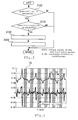
- Fig. 3 is a flowchart for explaining a control routine executed by the controller in Embodiment 1 of the present invention.
- the precondition here is whether or not an operation condition is capable of active control, whether or not it is during the active control or the like, and shall be set in advance and stored in the controller 14. If the precondition is not found to be satisfied at Step S102, the processing this time is finished.
- the precondition is found to be satisfied at Step S102, then, it is determined whether a learning condition is satisfied or not (S104).
- the learning condition is, for example, whether or not the catalyst 6 is in an active state, whether or not the downstream side of the catalyst 6 is fluctuated between a predetermined rich air/fuel ratio and lean air/fuel ratio and the like, and shall be set in advance and stored in the controller 14. If the learning condition is not found to be satisfied at Step S104, the processing this time is finished for the moment.
- the air/fuel ratio in the optimally purified state is detected (S106). Specifically, in this Embodiment 1, a period during the active control and from which 2 seconds before and after the switching of the air/fuel ratio from the rich air/fuel ratio to the lean air/fuel ratio or from the lean air/fuel ratio to the rich air/fuel ratio are excluded is set as the optimally purified state. At Step S106, the output of the Rr sensor 12 during this period is repeatedly detected at every predetermined time until a predetermined number of samples is reached.
- the correction coefficient is calculated (S108).
- a difference between the output of the Rr sensor 12 detected at Step S106 and the reference output (14.6) is obtained. After that, an average value of this difference is calculated, and this average value is set as the correction coefficient. Subsequently, the processing this time is finished for the moment.
- the calculated average value (correction coefficient) is used as a learned value for the optimally purified states of the Fr sensor 10 and the Rr sensor 12.
- the outputs of the air/fuel ratio sensors 10 and 12 with respect to the optimally purified point of the catalyst 6 can be corrected, and control based on the optimally purified state can be executed.
- Embodiment 1 execution of the control for calculating the correction coefficient of the air/fuel ratio sensors 10 and 12 during the active control regardless of an operation region was explained.
- the present invention is not limited to that.
- An intake air amount largely affects catalyst purification performances.
- it may be so configured that an engine revolution speed is divided into several regions and the correction coefficient is calculated for each region.
- the outputs of the air/fuel ratio sensors 10 and 12 can be corrected with higher accuracy. This also applies to Embodiment 2.
- Embodiment 1 execution of the control for calculating the correction coefficient of the air/fuel ratio sensors 10 and 12 in this Embodiment 1 by using timing during execution of the active control which is a control for the other purposes such as deterioration determination of the catalyst 6 and the like was explained. By using this, the correction coefficient can be calculated efficiently.
- the present invention is not limited to that, and the active control may be executed separately for calculating the correction coefficient of the air/fuel ratio sensors 10 and 12. This also applies to Embodiment 2.
- Embodiment 1 in both the cases in which the rich air/fuel ratio is switched to the lean air/fuel ratio and the lean air/fuel ratio is switched to the rich air/fuel ratio, the case in which the output of the Rr sensor 12 is detected and used for calculation of the correction coefficient was explained.
- the catalyst 6 an oxygen emission speed can easily change depending on the deterioration state or poisoned state. And the influence can easily appear when the air/fuel ratio is changed from rich to lean. Therefore, it may be so configured that the correction coefficient is calculated by using only the output when the lean air/fuel ratio is switched to the rich air/fuel ratio in calculation of the correction coefficient of the Rr sensor 12 in the present invention. As a result, more proper correction coefficient can be obtained. This also applies to Embodiment 2.
- the air/fuel ratio sensor 10 on the upstream side is not limited to that.
- the upstream-side sensor of the catalyst 6 is used for controlling the air/fuel ratio on the upstream of the catalyst 6 in the active control to a predetermined rich air/fuel ratio and lean air/fuel ratio. Therefore, in the present invention, another sensor capable of detecting an air/fuel ratio on the upstream side of the catalyst 6 can be used instead of the air/fuel ratio sensor 10.
- the present invention is not limited to that in which a sensor for air/fuel ratio detection is arranged on the upstream of the catalyst 6 of the exhaust passage 4.
- the air/fuel ratio may be detected in accordance with an output of an in-cylinder pressure sensor installed in the internal combustion engine 2 without installing the air/fuel ratio sensor 10. This also applies to Embodiment 2.
- Embodiment 1 the case in which an average value of the difference between the output of the Rr sensor 12 and the reference output is used as the correction coefficient of the air/fuel ratio sensors 10 and 12 was explained.
- the calculation method of the correction coefficient for the air/fuel ratio sensors 10 and 12 is not limited to that and any method can be used as long as it is detected by another method in accordance with a difference from the reference output.
- the case in which the output of the Rr sensor 12 is detected plural times and the average value of them is used was explained, but the present invention is not limited to that, and one detected value may be used for calculation of the correction coefficient as it is. This also applies to Embodiment 2.
- the present invention is not limited to the case in which the correction coefficient for correcting both the air/fuel ratio sensors 10 and 12 is acquired, but a correction coefficient for correcting only the output of the air/fuel ratio sensor 12 may be acquired, for example. This also applies to Embodiment 2.
- the period during the active control and from which 2 seconds before and after the switching of the air/fuel ratio from the rich air/fuel ratio to the lean air/fuel ratio or from the lean air/fuel ratio to the rich air/fuel ratio are excluded corresponds to the "predetermined period during which the output of the air/fuel ratio sensor is equilibrated" in the present invention.
- the "correction coefficient calculating means" in the present invention is realized.
- Embodiment 2 has a configuration similar to that of the system in Fig. 1 . Moreover, the system in Embodiment 2 executes control similar to that of the system in Embodiment 1 except that a different period is specified as the predetermined period during which the output of the Rr sensor 12 is equilibrated. That is, in the system of the Embodiment 2, too, the output of the Rr sensor 12 in the optimally purified state is detected, and the correction coefficient is calculated on the basis of this output value. However, in Embodiment 2, only the output of the case in which a differentiated value of the output change is a predetermined value or less is used, and the correction coefficient is calculated on the basis of this output.
- Fig. 4 is a diagram illustrating the output of the Rr sensor 12 and its differentiated value. Moreover, an upper curve in Fig. 4 is an output of the Rr sensor 12, while a lower curve indicates a value obtained by differentiating the output change of the Rr sensor 12. Moreover, in Fig. 4 , a shaded portion indicated by (b) is the optimally purified state.
- the differentiated value As illustrated in Fig. 4 , when the air/fuel ratio of an exhaust gas on the downstream of the catalyst is largely changed from the rich air/fuel ratio to the lean air/fuel ratio or to the contrary, it is confirmed that its differentiated value also increases. Moreover, in the optimally purified state, the differentiated value also shows a stable value. However, the output of the Rr sensor 12 might include a noise, and in this case, the differentiated value largely changes in the optimally purified state, too.
- Embodiment 2 a differential width for the noise is acquired in advance by an experiment or the like, and an allowable differential width (allowable range) is determined. If the differentiated value is contained in this allowable range, the output of the Rr sensor 12 is used for calculation of the correction coefficient.
- a calculating method and a correcting method of the correction coefficient are similar to those in Embodiment 1, and an average value of a difference between the output and the stoichiometric air/fuel ratio 14.6 is acquired, and this is used as the correction coefficient.
- the period during which the differentiated value is contained in the allowable range corresponds to the "predetermined period during which the output of the air/fuel ratio sensor is equilibrated" of the present invention.
- the "predetermined period during which the output of the air/fuel ratio sensor is equilibrated” is not limited to this. For example, it may be so configured that only the period during which the period in which the differentiated value is contained in the allowable range continues for a certain time is set as the "predetermined period" of the present invention, and only the output in this period is used for calculation of the correction coefficient.
Landscapes
- Engineering & Computer Science (AREA)
- Chemical & Material Sciences (AREA)
- Combustion & Propulsion (AREA)
- Mechanical Engineering (AREA)
- General Engineering & Computer Science (AREA)
- Analytical Chemistry (AREA)
- Health & Medical Sciences (AREA)
- Chemical Kinetics & Catalysis (AREA)
- Toxicology (AREA)
- Combined Controls Of Internal Combustion Engines (AREA)
- Electrical Control Of Air Or Fuel Supplied To Internal-Combustion Engine (AREA)
- Exhaust Gas After Treatment (AREA)
Abstract
Description
- The present invention relates to a correction device for an air/fuel ratio sensor. More specifically, the present invention relates to a correction device for correcting an output of an air/fuel ratio sensor installed on the downstream of a catalyst of an exhaust passage of an internal combustion engine.
- For example,
Patent Literature 1 discloses a catalyst deterioration detecting device for an internal combustion engine. In this catalyst deterioration detecting device, an air/fuel ratio sensor is installed on the upstream of the catalyst, while an electromotive force-type oxygen sensor is installed on the downstream. In deterioration detection of a catalyst by this catalyst deterioration detecting device, an air/fuel ratio on the upstream of the catalyst is forcedly controlled so as to fluctuate between a predetermined rich air/fuel ratio and a lean air/fuel ratio. Then, a temporal value until output of the oxygen sensor on the downstream side changes from a lean output to a rich output or a temporal value until a lean output is detected from a rich output is detected in this control. In this deterioration detection of the catalyst, an oxygen storage capacity of the catalyst is calculated on the basis of such temporal value, and moreover, deterioration of the catalyst is determined on the basis of whether the calculated oxygen storage capacity is larger than a predetermined value or not. -
- Patent Literature 1: Japanese Patent Laid-Open No.
2003-097334 - Patent Literature 2: Japanese Patent Laid-Open No.
2006-002579 - Patent Literature 3: Japanese Patent Laid-Open No.
2005-120870 - Patent Literature 4: Japanese Patent Laid-Open No.
6-280662 - An electromotive force-type oxygen sensor largely depends on an amount of a gas or concentration of a gas to be detected and has a feature that it is difficult to obtain an output for a gas with low concentration or a low flow rate. Therefore, if concentration of an exhaust gas exhausted to the downstream of the catalyst becomes further lower due to stricter regulation of exhaust gas or the like, it is concerned that the electromotive force-type oxygen sensor cannot accurately detect a change in the air/fuel ratio on the downstream of the catalyst any longer.
- Moreover, the lower the concentration of the gas to be detected becomes, the more output response of the oxygen sensor tends to be delayed. Therefore, in the low-concentration exhaust gas environment, it becomes difficult to detect a change in the air/fuel ratio between a rich air/fuel ratio and a lean air/fuel ratio immediately upon fluctuation. Therefore, it is considered to become difficult to maintain control accuracy high on the basis of an output change of the oxygen sensor on the downstream side such as catalyst deterioration detection as the above described prior-art technology.
- In response to that, as a sensor on the catalyst downstream side, a limiting-current type air/fuel ratio sensor, for example, can be employed. With the limiting-current type air/fuel ratio sensor, an air/fuel ratio of an exhaust gas with extremely low concentration can be detected accurately to some degree. However, in the air/fuel ratio sensor, too, its output might be shifted due to deterioration over time, initial variation and the like. In such cases, it is difficult to maintain high accuracy in control such as catalyst deterioration determination or the like due to an output error of the air/fuel ratio sensor.
- As described above, the present invention has an object to solve the above problems and to provide a correction device for an air/fuel ratio sensor which is improved to be able to correct its output properly when an air/fuel ratio sensor is installed on the catalyst downstream.
- To achieve the above described object, the present invention provides a correction device for an air/fuel ratio sensor that includes:
- air/fuel ratio control means for controlling an air/fuel ratio of an exhaust gas on the upstream side from a catalyst installed in an exhaust passage of an internal combustion engine to switch between a rich air/fuel ratio which is richer and a lean air/fuel ratio which is leaner than a stoichiometric air/fuel ratio;
- an air/fuel ratio sensor which issues an output according to the air/fuel ratio of an exhaust gas on the downstream from the catalyst of the exhaust passage; and
- correction coefficient calculating means for calculating a correction coefficient for correcting an output of the air/fuel ratio sensor in accordance with a difference between an output of the air/fuel ratio sensor in a predetermined period during an air/fuel ratio control by the air/fuel ratio control means and during which an output of the air/fuel ratio sensor installed on the downstream from the catalyst is equilibrated and a reference output corresponding to the stoichiometric air/fuel ratio.
- In this invention, the predetermined period may be a period from after a first time has elapsed since the air/fuel ratio is switched from the rich air/fuel ratio to the lean air/fuel ratio on the upstream side from the catalyst, by the air/fuel ratio control means, until a second time before the lean air/fuel ratio is switched to the rich air/fuel ratio again, and/or a period from after a third time has elapsed since the lean air/fuel ratio is switched to the rich air/fuel ratio, until a fourth time before the rich air/fuel ratio is switched to the lean air/fuel ratio. Here, the first time to the fourth time may be same time or different time.
- Alternatively, the predetermined period may be a period from after a first time has elapsed since the air/fuel ratio is switched from the rich air/fuel ratio to the lean air/fuel ratio on the upstream side from the catalyst, by the air/fuel ratio control means, until a second time before the lean air/fuel ratio is switched to the rich air/fuel ratio. Here, the first and second times may be same time or different time.
- Further, the correction device for an air/fuel ratio sensor of this invention may further includes differentiated value calculating means for calculating a differentiated value of a change in an output of the air/fuel ratio sensor. In this case, the predetermined period may be a period during which the differentiated value is within a predetermined allowable range.
- Further, in case which uses the differentiated value calculating means, the predetermined period may be a period during which the period in which the differentiated value is within the allowable range continues for a certain time.
- Further, the predetermined period may be a period during which the differentiated value is within a predetermined allowable range and a period from after the air/fuel ratio of the air/fuel ratio sensor is switched from the lean air/fuel ratio to the rich air/fuel ratio, until the air/fuel ratio is switched to the lean air/fuel ratio again.
- Further, as an output of the air/fuel ratio sensor in each predetermined period, an average value of the output of the air/fuel ratio sensor detected plural times during the predetermined period may be used.
- According to the present invention, if control to switch an air/fuel ratio on the upstream of a catalyst between a rich air/fuel ratio and a lean air/fuel ratio is executed, the catalyst enters an optimally state for purifying during a period after switching of the air/fuel ratio, and an exhaust gas exhausted to downstream side of the catalyst in that state becomes an exhaust gas close to a stoichiometric air/fuel ratio reduced to an optimal state. During such state, an output of the air/fuel ratio sensor is made stable into an output corresponding to the stoichiometric air/fuel ratio and is considered to be equilibrated. Therefore, during a period during which the output of the air/fuel ratio sensor is equilibrated, by comparing an output of the air/fuel ratio sensor and a reference output corresponding to the stoichiometric air/fuel ratio, discrepancy from the reference output of the air/fuel ratio sensor can be obtained. Moreover, by calculating an output correction coefficient of the air/fuel ratio sensor on the basis of this discrepancy, discrepancy caused by deterioration of the air/fuel ratio sensor or the like can be corrected.
- Moreover, in the present invention, for those using a period excluding predetermined time before and after the switching of the air/fuel ratio as a predetermined period, an output during a period during which the catalyst enters the optimal state and an output of the air/fuel ratio sensor is made stable can be used more reliably.
- Moreover, in the present invention, for those in which a correction coefficient of the air/fuel ratio sensor is obtained on the basis of an output of the air/fuel ratio sensor if a differentiated value of an output change of the air/fuel ratio sensor is within a predetermined allowable range, a noise included in the output of the air/fuel ratio sensor or the like can be removed more reliably, and a more proper output correction coefficient of the air/fuel ratio sensor can be obtained.
- Moreover, an oxygen emission speed of the catalyst is easily influenced by a poisoned state or deterioration state, and the influence tends to appear if a rich air/fuel ratio is switched to a lean air/fuel ratio. Therefore, in the present invention, a period when the lean air/fuel ratio is switched to the rich air/fuel ratio is set as a predetermined period, and for those using the output during that period for correction of the air/fuel ratio sensor, correction of the air/fuel ratio sensor can be executed with higher accuracy.
-
- [
Fig.1] Fig. 1 is a schematic diagram for explaining an entire configuration of a system inEmbodiment 1 of the present invention. - [
Fig.2] Fig. 2 is a diagram for explaining contents of the control inEmbodiment 1 of the present invention. - [
Fig.3] Fig. 3 is a flowchart for explaining a control routine executed by the controller inEmbodiment 1 of the present invention. - [
Fig.4] Fig. 4 is a diagram for explaining contents of the control in Embodiment 2 of the present invention. - Embodiments of the present invention will be described below by referring to the attached drawings. In each figure, the same or equivalent portions are given the same reference numerals and the explanation will be simplified or omitted.
-
Fig. 1 is a schematic diagram for explaining an entire configuration of a system inEmbodiment 1 of the present invention. The system inFig. 1 is mounted on a vehicle or the like and used. InFig. 1 , in an exhaust passage 4 of an internal combustion engine 2,catalysts catalyst 6 can purify an exhaust gas by oxidizing carbon monoxide (CO) and hydrocarbon (HC) exhausted from the internal combustion engine 2 and by reducing nitrogen oxides (NOx). - On the upstream side from the
catalyst 6 of the exhaust passage 4, an air/fuel ratio sensor 10 is installed. On the downstream side from thecatalyst 6 of the exhaust passage 4 and on the upstream side of thecatalyst 8, an air/fuel ratio sensor 12 is installed. The both air/fuel ratio sensors fuel ratio sensor 10 on the upstream side of thecatalyst 6 is also referred to as an "Fr sensor 10" and the air/fuel ratio sensor 12 on the downstream side as "Rr sensor 12". - The system in
Fig. 1 is provided with acontroller 14. Thecontroller 14 integrally controls the entire system of the internal combustion engine 2. On the output side of thecontroller 14, various actuators are connected, while on the input side, various sensors such as the air/fuel ratio sensors controller 14 detects various types of information required for operation of the internal combustion engine 2 such as an air/fuel ratio of the exhaust gas, engine revolution speed and others upon reception of sensor signals and also operates each of the actuators in accordance with a predetermined control program. There are a large number of actuators and sensors connected to thecontroller 14, but the explanation will be omitted in this description. In this system, control executed by thecontroller 14 includes control for correcting an output of theRr sensor 12. -
Fig. 2 is a diagram for explaining contents of the control inEmbodiment 1 of the present invention. InFig. 2 , a straight line on the IN side (upper side in the figure) indicates an air/fuel ratio of the exhaust gas flowing into thecatalyst 6, while a curved line on the OUT side (lower side in the figure) indicates an output of theRr sensor 12 to the exhaust gas flowing out of thecatalyst 6. - As illustrated in
Fig. 2 , the control for correcting theRr sensor 12 is executed during active control in which an air/fuel ratio of an exhaust gas to be made to flow into thecatalyst 6 is fluctuated between a rich air/fuel ratio which is richer and a lean air/fuel ratio which is leaner than a stoichiometric air/fuel ratio. More specifically, in the example inFig. 2 , control of forcedly switching between the rich air/fuel ratio, 14.1 and the lean air/fuel ratio, 15.1 is executed. This active control is control executed for other purposes such as deterioration determination of thecatalyst 6 and the like, for example, and is executed on the basis of a control program stored in thecontroller 14. - In this active control, the air/fuel ratio of the exhaust gas on the IN side flowing into the
catalyst 6 is switched from the rich air/fuel ratio to the lean air/fuel ratio and maintained at the lean air/fuel ratio, for example. At this time, thecatalyst 6 oxidizes or reduces an unburned component of the exhaust gas in a lean atmosphere and purifies it to an optimal state. The state in which the exhaust gas is purified optimally as above shall be referred to as "optimally purified state". In this optimally purified state, the exhaust gas purified close to the stoichiometric air/fuel ratio is exhausted to the downstream of thecatalyst 6. Therefore, as illustrated at (a) inFig. 2 , theRr sensor 12 stably outputs a value corresponding to the stoichiometric air/fuel ratio. - However, if the lean exhaust gas continuously flows into the
catalyst 6, thecatalyst 6 stores oxygen to the maximum and enters a state in which oxygen cannot be stored any longer. In this state, thecatalyst 6 cannot purify (reduce) a lean component (NOx and the like) any longer and the exhaust gas in a lean atmosphere begins to be exhausted to the downstream of thecatalyst 6. Therefore, the output of theRr sensor 12 becomes a value indicating a predetermined lean air/fuel ratio. - If the output of the
Rr sensor 12 becomes a value indicating leanness, the air/fuel ratio of the exhaust gas on the IN side of thecatalyst 6 is switched to a rich air/fuel ratio. The rich exhaust gas flows into thecatalyst 6, and inside thecatalyst 6, equilibration of the gas progresses, and the "optimally purified state" in which the rich exhaust gas is purified to the optimal state is obtained. In this state, the purified exhaust gas close to the stoichiometric air/fuel ratio is exhausted to the downstream side of thecatalyst 6. Therefore, as illustrated inFig. 2(a) , the output of theRr sensor 12 is made stable into a value corresponding to the stoichiometric air/fuel ratio from the value indicating leanness. - Subsequently, if the rich exhaust gas continuously flows into the
catalyst 6, thecatalyst 6 enters a state in which it cannot purify the inflow exhaust gas in a rich atmosphere any longer. In this state, the exhaust gas in the rich atmosphere flows out to the downstream of thecatalyst 6. Therefore, the output of theRr sensor 12 becomes a value indicating the rich atmosphere. - Subsequently, if the air/fuel ratio is switched again to the lean atmosphere, the equilibration of the gas progresses again in the
catalyst 6, and a "catalyst optimal state" in which the exhaust gas is purified to the optimal state is obtained. In this state, the output of theRr sensor 12 is made stable again to a value corresponding to the stoichiometric air/fuel ratio. - During the active control, the above described rich air/fuel ratio and lean air/fuel ratio are repeatedly switched. If the catalyst enters the optimally purified state for a certain period after the switching, the output of the
Rr sensor 12 also indicates a value close to the stoichiometric air/fuel ratio stably. Here, the output of theRr sensor 12 in the optimally purified state theoretically indicates a reference output (14.6) which is an output corresponding to the stoichiometric air/fuel ratio. - However, even in the optimally purified state, an output value of the
Rr sensor 12 might not become a value corresponding to the stoichiometric air/fuel ratio due to deterioration over time of theFr sensor 10 or theRr sensor 12, initial variation and the like. The discrepancy between the sensor output and the reference output in the optimally purified state is considered to be discrepancy over the entire output of theRr sensor 12. - As described above, in this
Embodiment 1, the output of theRr sensor 12 in the optimally purified state during the active control is detected, a difference between an output detected value and the reference output (14.6) is acquired, and an average value of this difference is calculated. This average value is used as an output correction coefficient for theRr sensor 12. - However, it takes some time after the air/fuel ratio is switched from the rich air/fuel ratio to the lean air/fuel ratio or from the lean air/fuel ratio to the rich air/fuel ratio until the
Rr sensor 12 issues a stable output. Therefore, in thisEmbodiment 1, a period from 2 seconds after the switching to the rich air/fuel ratio to 2 seconds before the switching to the lean air/fuel ratio and a period from 2 seconds after the switching to the lean air/fuel ratio to 2 seconds before the switching to the rich air/fuel ratio are set as catalyst optimal states, and the output of theRr sensor 12 during these periods is detected, and a correction coefficient is calculated. -
Fig. 3 is a flowchart for explaining a control routine executed by the controller inEmbodiment 1 of the present invention. In the control inFig. 3 , first, it is determined whether or not a precondition is satisfied (S102). The precondition here is whether or not an operation condition is capable of active control, whether or not it is during the active control or the like, and shall be set in advance and stored in thecontroller 14. If the precondition is not found to be satisfied at Step S102, the processing this time is finished. - On the other hand, if the precondition is found to be satisfied at Step S102, then, it is determined whether a learning condition is satisfied or not (S104). Here, the learning condition is, for example, whether or not the
catalyst 6 is in an active state, whether or not the downstream side of thecatalyst 6 is fluctuated between a predetermined rich air/fuel ratio and lean air/fuel ratio and the like, and shall be set in advance and stored in thecontroller 14. If the learning condition is not found to be satisfied at Step S104, the processing this time is finished for the moment. - On the other hand, if the learning condition is found to be established at Step S104, the air/fuel ratio in the optimally purified state is detected (S106). Specifically, in this
Embodiment 1, a period during the active control and from which 2 seconds before and after the switching of the air/fuel ratio from the rich air/fuel ratio to the lean air/fuel ratio or from the lean air/fuel ratio to the rich air/fuel ratio are excluded is set as the optimally purified state. At Step S106, the output of theRr sensor 12 during this period is repeatedly detected at every predetermined time until a predetermined number of samples is reached. - Subsequently, the correction coefficient is calculated (S108). In calculation of the correction coefficient, first, a difference between the output of the
Rr sensor 12 detected at Step S106 and the reference output (14.6) is obtained. After that, an average value of this difference is calculated, and this average value is set as the correction coefficient. Subsequently, the processing this time is finished for the moment. - The calculated average value (correction coefficient) is used as a learned value for the optimally purified states of the
Fr sensor 10 and theRr sensor 12. For example, in feedback control of the air/fuel ratio using the air/fuel ratio sensors 
- As described above, by executing correction on the basis of the sensor output in the optimally purified state, without being affected by discrepancy of a purification point caused by deterioration of the
catalyst 6, discrepancy of the stoichiometric air/fuel ratio caused by a change in the fuel, output discrepancy of the sensor due to an increase in a rich gas and the like, the outputs of the air/fuel ratio sensors catalyst 6 can be corrected, and control based on the optimally purified state can be executed. - In this
Embodiment 1, execution of the control for calculating the correction coefficient of the air/fuel ratio sensors fuel ratio sensors - Moreover, in this
Embodiment 1, execution of the control for calculating the correction coefficient of the air/fuel ratio sensors Embodiment 1 by using timing during execution of the active control which is a control for the other purposes such as deterioration determination of thecatalyst 6 and the like was explained. By using this, the correction coefficient can be calculated efficiently. However, the present invention is not limited to that, and the active control may be executed separately for calculating the correction coefficient of the air/fuel ratio sensors - Moreover, in
Embodiment 1, in both the cases in which the rich air/fuel ratio is switched to the lean air/fuel ratio and the lean air/fuel ratio is switched to the rich air/fuel ratio, the case in which the output of theRr sensor 12 is detected and used for calculation of the correction coefficient was explained. However, in thecatalyst 6, an oxygen emission speed can easily change depending on the deterioration state or poisoned state. And the influence can easily appear when the air/fuel ratio is changed from rich to lean. Therefore, it may be so configured that the correction coefficient is calculated by using only the output when the lean air/fuel ratio is switched to the rich air/fuel ratio in calculation of the correction coefficient of theRr sensor 12 in the present invention. As a result, more proper correction coefficient can be obtained. This also applies to Embodiment 2. - Moreover, in this
Embodiment 1, the case in which the limiting current type air/fuel ratio sensors catalyst 6, respectively, was explained. However, in the present invention, the air/fuel ratio sensor 10 on the upstream side is not limited to that. The upstream-side sensor of thecatalyst 6 is used for controlling the air/fuel ratio on the upstream of thecatalyst 6 in the active control to a predetermined rich air/fuel ratio and lean air/fuel ratio. Therefore, in the present invention, another sensor capable of detecting an air/fuel ratio on the upstream side of thecatalyst 6 can be used instead of the air/fuel ratio sensor 10. Moreover, the present invention is not limited to that in which a sensor for air/fuel ratio detection is arranged on the upstream of thecatalyst 6 of the exhaust passage 4. For example, the air/fuel ratio may be detected in accordance with an output of an in-cylinder pressure sensor installed in the internal combustion engine 2 without installing the air/fuel ratio sensor 10. This also applies to Embodiment 2. - Moreover, in this
Embodiment 1, the case in which an average value of the difference between the output of theRr sensor 12 and the reference output is used as the correction coefficient of the air/fuel ratio sensors fuel ratio sensors Rr sensor 12 is detected plural times and the average value of them is used was explained, but the present invention is not limited to that, and one detected value may be used for calculation of the correction coefficient as it is. This also applies to Embodiment 2. - Moreover, the present invention is not limited to the case in which the correction coefficient for correcting both the air/
fuel ratio sensors fuel ratio sensor 12 may be acquired, for example. This also applies to Embodiment 2. - For example, in the
Embodiment 1, the period during the active control and from which 2 seconds before and after the switching of the air/fuel ratio from the rich air/fuel ratio to the lean air/fuel ratio or from the lean air/fuel ratio to the rich air/fuel ratio are excluded corresponds to the "predetermined period during which the output of the air/fuel ratio sensor is equilibrated" in the present invention. By means of execution of Steps S106 and S108 in thisEmbodiment 1, the "correction coefficient calculating means" in the present invention is realized. - Embodiment 2 has a configuration similar to that of the system in
Fig. 1 . Moreover, the system in Embodiment 2 executes control similar to that of the system inEmbodiment 1 except that a different period is specified as the predetermined period during which the output of theRr sensor 12 is equilibrated. That is, in the system of the Embodiment 2, too, the output of theRr sensor 12 in the optimally purified state is detected, and the correction coefficient is calculated on the basis of this output value. However, in Embodiment 2, only the output of the case in which a differentiated value of the output change is a predetermined value or less is used, and the correction coefficient is calculated on the basis of this output. -
Fig. 4 is a diagram illustrating the output of theRr sensor 12 and its differentiated value. Moreover, an upper curve inFig. 4 is an output of theRr sensor 12, while a lower curve indicates a value obtained by differentiating the output change of theRr sensor 12. Moreover, inFig. 4 , a shaded portion indicated by (b) is the optimally purified state. - As illustrated in
Fig. 4 , when the air/fuel ratio of an exhaust gas on the downstream of the catalyst is largely changed from the rich air/fuel ratio to the lean air/fuel ratio or to the contrary, it is confirmed that its differentiated value also increases. Moreover, in the optimally purified state, the differentiated value also shows a stable value. However, the output of theRr sensor 12 might include a noise, and in this case, the differentiated value largely changes in the optimally purified state, too. - Therefore, in Embodiment 2, a differential width for the noise is acquired in advance by an experiment or the like, and an allowable differential width (allowable range) is determined. If the differentiated value is contained in this allowable range, the output of the
Rr sensor 12 is used for calculation of the correction coefficient. A calculating method and a correcting method of the correction coefficient are similar to those inEmbodiment 1, and an average value of a difference between the output and the stoichiometric air/fuel ratio 14.6 is acquired, and this is used as the correction coefficient. - As described above, by using only the output of a period during which the differentiated value is contained in the allowable range as an output in calculation of the correction coefficient, a noise included in the output of the
Rr sensor 12 can be cut. As a result, more proper correction coefficient can be calculated, and accuracy of the air/fuel ratio control and the like can be improved. - In this Embodiment 2, the period during which the differentiated value is contained in the allowable range corresponds to the "predetermined period during which the output of the air/fuel ratio sensor is equilibrated" of the present invention. In this second Embodiment 2, the case in which the output of the
Rr sensor 12 is used for calculation of the sensor output correction coefficient in this period was explained. However, in the present invention, the "predetermined period during which the output of the air/fuel ratio sensor is equilibrated" is not limited to this. For example, it may be so configured that only the period during which the period in which the differentiated value is contained in the allowable range continues for a certain time is set as the "predetermined period" of the present invention, and only the output in this period is used for calculation of the correction coefficient. - In the above embodiments, when the number, quantity, amount, range and the like of each element are referred to, the present invention is not limited to the referred number except when particularly explicitly indicated or obviously specified to the number in principle. Moreover, the structures or the like explained in these embodiments are not necessarily indispensable to the present invention except when particularly explicitly indicated or obviously specified therefor in principle.
-
- 2
- internal combustion engine
- 6, 8
- catalysts
- 10
- air/fuel ratio sensor (Fr sensor)
- 12
- air/fuel ratio sensors (Rr sensor)
- 14
- controller
Claims (7)
- A correction device for an air/fuel ratio sensor, comprising:air/fuel ratio control means for controlling an air/fuel ratio of an exhaust gas on the upstream side from a catalyst installed in an exhaust passage of an internal combustion engine to switch between a rich air/fuel ratio which is richer and a lean air/fuel ratio which is leaner than a stoichiometric air/fuel ratio;an air/fuel ratio sensor which issues an output according to the air/fuel ratio of an exhaust gas on the downstream from the catalyst of the exhaust passage; andcorrection coefficient calculating means for calculating a correction coefficient for correcting an output of the air/fuel ratio sensor in accordance with a difference between an output of the air/fuel ratio sensor in a predetermined period during an air/fuel ratio control by the air/fuel ratio control means and during which an output of the air/fuel ratio sensor installed on the downstream from the catalyst is equilibrated and a reference output corresponding to the stoichiometric air/fuel ratio.
- The correction device for an air/fuel ratio sensor according to claim 1, wherein
the predetermined period is a period from after a first time has elapsed since the air/fuel ratio is switched from the rich air/fuel ratio to the lean air/fuel ratio on the upstream side from the catalyst, by the air/fuel ratio control means, until a second time before the lean air/fuel ratio is switched to the rich air/fuel ratio again, and/or a period from after a third time has elapsed since the lean air/fuel ratio is switched to the rich air/fuel ratio, until a fourth time before the rich air/fuel ratio is switched to the lean air/fuel ratio. - The correction device for an air/fuel ratio sensor according to claim 1, wherein
the predetermined period is a period from after a first time has elapsed since the air/fuel ratio is switched from the rich air/fuel ratio to the lean air/fuel ratio on the upstream side from the catalyst, by the air/fuel ratio control means, until a second time before the lean air/fuel ratio is switched to the rich air/fuel ratio. - The correction device for an air/fuel ratio sensor according to claim 1, further comprising:differentiated value calculating means for calculating a differentiated value of a change in an output of the air/fuel ratio sensor, whereinthe predetermined period is a period during which the differentiated value is within a predetermined allowable range.
- The correction device for an air/fuel ratio sensor according to claim 4, wherein
the predetermined period is a period during which the period in which the differentiated value is within the allowable range continues for a certain time. - The correction device for an air/fuel ratio sensor according to claim 4 or 5, wherein
the predetermined period is further a period from after the air/fuel ratio of the air/fuel ratio sensor is switched from the lean air/fuel ratio to the rich air/fuel ratio, until the air/fuel ratio is switched to the lean air/fuel ratio again. - The correction device for an air/fuel ratio sensor according to any one of claims 1 to 6, wherein
as an output of the air/fuel ratio sensor in the predetermined period, an average value of the output of the air/fuel ratio sensor detected plural times during the predetermined period is used.
Applications Claiming Priority (1)
| Application Number | Priority Date | Filing Date | Title |
|---|---|---|---|
| PCT/JP2011/061532 WO2012157111A1 (en) | 2011-05-19 | 2011-05-19 | Correction device for air/fuel ratio sensor |
Publications (3)
| Publication Number | Publication Date |
|---|---|
| EP2711528A1 true EP2711528A1 (en) | 2014-03-26 |
| EP2711528A4 EP2711528A4 (en) | 2016-01-06 |
| EP2711528B1 EP2711528B1 (en) | 2019-04-10 |
Family
ID=47176473
Family Applications (1)
| Application Number | Title | Priority Date | Filing Date |
|---|---|---|---|
| EP11865664.4A Not-in-force EP2711528B1 (en) | 2011-05-19 | 2011-05-19 | Correction device for air/fuel ratio sensor |
Country Status (5)
| Country | Link |
|---|---|
| US (2) | US9347352B2 (en) |
| EP (1) | EP2711528B1 (en) |
| JP (1) | JP5761340B2 (en) |
| CN (1) | CN103547784B (en) |
| WO (1) | WO2012157111A1 (en) |
Families Citing this family (3)
| Publication number | Priority date | Publication date | Assignee | Title |
|---|---|---|---|---|
| WO2012157111A1 (en) * | 2011-05-19 | 2012-11-22 | トヨタ自動車株式会社 | Correction device for air/fuel ratio sensor |
| JP5668768B2 (en) * | 2013-02-25 | 2015-02-12 | トヨタ自動車株式会社 | Control device for internal combustion engine |
| JP6256240B2 (en) | 2014-07-28 | 2018-01-10 | トヨタ自動車株式会社 | Control device for internal combustion engine |
Family Cites Families (19)
| Publication number | Priority date | Publication date | Assignee | Title |
|---|---|---|---|---|
| JP2917173B2 (en) * | 1990-09-04 | 1999-07-12 | 株式会社ユニシアジェックス | Air-fuel ratio control device for internal combustion engine |
| JP3651007B2 (en) | 1991-09-24 | 2005-05-25 | 株式会社デンソー | Air-fuel ratio control device for internal combustion engine |
| JPH06280662A (en) | 1993-03-30 | 1994-10-04 | Mazda Motor Corp | Failure detection device for air-fuel ratio control device |
| JPH0979072A (en) | 1995-09-11 | 1997-03-25 | Unisia Jecs Corp | Air-fuel ratio learning controller for internal combustion engine |
| JPH09125938A (en) | 1995-11-07 | 1997-05-13 | Hitachi Ltd | Engine control device |
| JPH10169500A (en) * | 1996-12-12 | 1998-06-23 | Unisia Jecs Corp | Air-fuel ratio sensor output correction device |
| DE60116158T2 (en) * | 2000-02-23 | 2006-06-29 | Nissan Motor Co. Ltd. | Air-fuel ratio control system |
| US7198952B2 (en) * | 2001-07-18 | 2007-04-03 | Toyota Jidosha Kabushiki Kaisha | Catalyst deterioration detecting apparatus and method |
| JP4474817B2 (en) | 2001-09-19 | 2010-06-09 | トヨタ自動車株式会社 | Catalyst deterioration detection device for internal combustion engine |
| JP2005120870A (en) | 2003-10-15 | 2005-05-12 | Toyota Motor Corp | Air-fuel ratio control device for internal combustion engine |
| JP4265486B2 (en) | 2004-06-15 | 2009-05-20 | 日産自動車株式会社 | Air-fuel ratio control device for internal combustion engine |
| JP4345688B2 (en) * | 2005-02-24 | 2009-10-14 | 株式会社日立製作所 | Diagnostic device and control device for internal combustion engine |
| JP3941828B2 (en) * | 2005-09-15 | 2007-07-04 | トヨタ自動車株式会社 | Air-fuel ratio control device for internal combustion engine |
| JP4679335B2 (en) * | 2005-11-01 | 2011-04-27 | 日立オートモティブシステムズ株式会社 | Control device for internal combustion engine |
| DE102005059794B3 (en) | 2005-12-14 | 2007-03-29 | Siemens Ag | Exhaust gas probe calibrating method for use in internal combustion engine, involves detecting plateau phase of measuring signals of probe, after transfer of parameter of fat air-fuel ratio to parameter of lean air-fuel ratio |
| JP4329799B2 (en) * | 2006-09-20 | 2009-09-09 | トヨタ自動車株式会社 | Air-fuel ratio control device for internal combustion engine |
| JP4380745B2 (en) * | 2007-07-20 | 2009-12-09 | トヨタ自動車株式会社 | Device for acquiring degree of deterioration of catalyst of internal combustion engine |
| JP5404262B2 (en) * | 2009-09-04 | 2014-01-29 | ダイハツ工業株式会社 | Air-fuel ratio control device |
| WO2012157111A1 (en) * | 2011-05-19 | 2012-11-22 | トヨタ自動車株式会社 | Correction device for air/fuel ratio sensor |
-
2011
- 2011-05-19 WO PCT/JP2011/061532 patent/WO2012157111A1/en not_active Ceased
- 2011-05-19 JP JP2013514938A patent/JP5761340B2/en not_active Expired - Fee Related
- 2011-05-19 CN CN201180070990.0A patent/CN103547784B/en not_active Expired - Fee Related
- 2011-05-19 EP EP11865664.4A patent/EP2711528B1/en not_active Not-in-force
- 2011-05-19 US US14/114,770 patent/US9347352B2/en not_active Expired - Fee Related
-
2016
- 2016-04-20 US US15/133,310 patent/US10161343B2/en active Active
Also Published As
| Publication number | Publication date |
|---|---|
| JP5761340B2 (en) | 2015-08-12 |
| CN103547784A (en) | 2014-01-29 |
| US10161343B2 (en) | 2018-12-25 |
| US20140075924A1 (en) | 2014-03-20 |
| US20160230690A1 (en) | 2016-08-11 |
| US9347352B2 (en) | 2016-05-24 |
| EP2711528B1 (en) | 2019-04-10 |
| JPWO2012157111A1 (en) | 2014-07-31 |
| EP2711528A4 (en) | 2016-01-06 |
| WO2012157111A1 (en) | 2012-11-22 |
| CN103547784B (en) | 2016-05-04 |
Similar Documents
| Publication | Publication Date | Title |
|---|---|---|
| US8899015B2 (en) | Catalyst degradation detection device | |
| EP1837503B1 (en) | Catalyst deterioration detecting apparatus | |
| US7793489B2 (en) | Fuel control for robust detection of catalytic converter oxygen storage capacity | |
| JP2001227384A (en) | Engine exhaust purification device | |
| JP6018543B2 (en) | Catalyst oxygen storage amount estimation method for internal combustion engine, air-fuel ratio control method for internal combustion engine, catalyst oxygen storage amount estimation device, air-fuel ratio control device for internal combustion engine, and motorcycle | |
| JP2016031041A (en) | Control device for internal combustion engine | |
| JP2004069457A (en) | Deterioration detector for air-fuel ratio detector | |
| US10161343B2 (en) | Correction device for air/fuel ratio sensor | |
| JP5515967B2 (en) | Diagnostic equipment | |
| JP6565432B2 (en) | Catalyst deterioration diagnosis device for internal combustion engine | |
| JP5783091B2 (en) | Output correction device for air-fuel ratio sensor | |
| JP2009002170A (en) | Air-fuel ratio control device for internal combustion engine | |
| JP4032840B2 (en) | Exhaust gas purification device for internal combustion engine | |
| JP2020026756A (en) | Engine control device and engine control method | |
| JP4190430B2 (en) | Oxygen sensor abnormality diagnosis device | |
| JP5761127B2 (en) | Catalyst deterioration diagnosis device | |
| JP4289133B2 (en) | Air-fuel ratio control device for internal combustion engine | |
| EP1801379B1 (en) | Exhaust purification system for internal combustion engine | |
| US20240309824A1 (en) | Engine controller | |
| US20230258140A1 (en) | Verfahren, Recheneinheit und Computerprogramm zum Betreiben einer Brennkraftmaschine | |
| JP5206129B2 (en) | Error control determination apparatus and error control determination method for air-fuel ratio control system | |
| JPH08291741A (en) | Device for determining catalyst deterioration of internal combustion engine | |
| JP2023175080A (en) | Catalytic ability detection device | |
| CN105822444A (en) | Supplementing and correcting device of air-fuel ratio sensor | |
| JP2007198288A (en) | Air-fuel ratio control device for internal combustion engine |
Legal Events
| Date | Code | Title | Description |
|---|---|---|---|
| PUAI | Public reference made under article 153(3) epc to a published international application that has entered the european phase |
Free format text: ORIGINAL CODE: 0009012 |
|
| 17P | Request for examination filed |
Effective date: 20131114 |
|
| AK | Designated contracting states |
Kind code of ref document: A1 Designated state(s): AL AT BE BG CH CY CZ DE DK EE ES FI FR GB GR HR HU IE IS IT LI LT LU LV MC MK MT NL NO PL PT RO RS SE SI SK SM TR |
|
| DAX | Request for extension of the european patent (deleted) | ||
| RA4 | Supplementary search report drawn up and despatched (corrected) |
Effective date: 20151207 |
|
| RIC1 | Information provided on ipc code assigned before grant |
Ipc: F02D 41/14 20060101ALI20151201BHEP Ipc: F02D 41/24 20060101ALI20151201BHEP Ipc: F02D 41/02 20060101ALN20151201BHEP Ipc: F02D 45/00 20060101AFI20151201BHEP |
|
| STAA | Information on the status of an ep patent application or granted ep patent |
Free format text: STATUS: EXAMINATION IS IN PROGRESS |
|
| 17Q | First examination report despatched |
Effective date: 20180612 |
|
| GRAP | Despatch of communication of intention to grant a patent |
Free format text: ORIGINAL CODE: EPIDOSNIGR1 |
|
| STAA | Information on the status of an ep patent application or granted ep patent |
Free format text: STATUS: GRANT OF PATENT IS INTENDED |
|
| INTG | Intention to grant announced |
Effective date: 20181106 |
|
| GRAS | Grant fee paid |
Free format text: ORIGINAL CODE: EPIDOSNIGR3 |
|
| GRAA | (expected) grant |
Free format text: ORIGINAL CODE: 0009210 |
|
| STAA | Information on the status of an ep patent application or granted ep patent |
Free format text: STATUS: THE PATENT HAS BEEN GRANTED |
|
| AK | Designated contracting states |
Kind code of ref document: B1 Designated state(s): AL AT BE BG CH CY CZ DE DK EE ES FI FR GB GR HR HU IE IS IT LI LT LU LV MC MK MT NL NO PL PT RO RS SE SI SK SM TR |
|
| REG | Reference to a national code |
Ref country code: GB Ref legal event code: FG4D |
|
| REG | Reference to a national code |
Ref country code: CH Ref legal event code: EP Ref country code: AT Ref legal event code: REF Ref document number: 1118984 Country of ref document: AT Kind code of ref document: T Effective date: 20190415 |
|
| REG | Reference to a national code |
Ref country code: IE Ref legal event code: FG4D |
|
| REG | Reference to a national code |
Ref country code: DE Ref legal event code: R096 Ref document number: 602011058050 Country of ref document: DE |
|
| REG | Reference to a national code |
Ref country code: DE Ref legal event code: R084 Ref document number: 602011058050 Country of ref document: DE |
|
| REG | Reference to a national code |
Ref country code: NL Ref legal event code: MP Effective date: 20190410 |
|
| REG | Reference to a national code |
Ref country code: LT Ref legal event code: MG4D |
|
| REG | Reference to a national code |
Ref country code: AT Ref legal event code: MK05 Ref document number: 1118984 Country of ref document: AT Kind code of ref document: T Effective date: 20190410 |
|
| PG25 | Lapsed in a contracting state [announced via postgrant information from national office to epo] |
Ref country code: NL Free format text: LAPSE BECAUSE OF FAILURE TO SUBMIT A TRANSLATION OF THE DESCRIPTION OR TO PAY THE FEE WITHIN THE PRESCRIBED TIME-LIMIT Effective date: 20190410 |
|
| PG25 | Lapsed in a contracting state [announced via postgrant information from national office to epo] |
Ref country code: LT Free format text: LAPSE BECAUSE OF FAILURE TO SUBMIT A TRANSLATION OF THE DESCRIPTION OR TO PAY THE FEE WITHIN THE PRESCRIBED TIME-LIMIT Effective date: 20190410 Ref country code: PT Free format text: LAPSE BECAUSE OF FAILURE TO SUBMIT A TRANSLATION OF THE DESCRIPTION OR TO PAY THE FEE WITHIN THE PRESCRIBED TIME-LIMIT Effective date: 20190910 Ref country code: FI Free format text: LAPSE BECAUSE OF FAILURE TO SUBMIT A TRANSLATION OF THE DESCRIPTION OR TO PAY THE FEE WITHIN THE PRESCRIBED TIME-LIMIT Effective date: 20190410 Ref country code: NO Free format text: LAPSE BECAUSE OF FAILURE TO SUBMIT A TRANSLATION OF THE DESCRIPTION OR TO PAY THE FEE WITHIN THE PRESCRIBED TIME-LIMIT Effective date: 20190710 Ref country code: SE Free format text: LAPSE BECAUSE OF FAILURE TO SUBMIT A TRANSLATION OF THE DESCRIPTION OR TO PAY THE FEE WITHIN THE PRESCRIBED TIME-LIMIT Effective date: 20190410 Ref country code: HR Free format text: LAPSE BECAUSE OF FAILURE TO SUBMIT A TRANSLATION OF THE DESCRIPTION OR TO PAY THE FEE WITHIN THE PRESCRIBED TIME-LIMIT Effective date: 20190410 Ref country code: ES Free format text: LAPSE BECAUSE OF FAILURE TO SUBMIT A TRANSLATION OF THE DESCRIPTION OR TO PAY THE FEE WITHIN THE PRESCRIBED TIME-LIMIT Effective date: 20190410 Ref country code: AL Free format text: LAPSE BECAUSE OF FAILURE TO SUBMIT A TRANSLATION OF THE DESCRIPTION OR TO PAY THE FEE WITHIN THE PRESCRIBED TIME-LIMIT Effective date: 20190410 |
|
| PG25 | Lapsed in a contracting state [announced via postgrant information from national office to epo] |
Ref country code: BG Free format text: LAPSE BECAUSE OF FAILURE TO SUBMIT A TRANSLATION OF THE DESCRIPTION OR TO PAY THE FEE WITHIN THE PRESCRIBED TIME-LIMIT Effective date: 20190710 Ref country code: GR Free format text: LAPSE BECAUSE OF FAILURE TO SUBMIT A TRANSLATION OF THE DESCRIPTION OR TO PAY THE FEE WITHIN THE PRESCRIBED TIME-LIMIT Effective date: 20190711 Ref country code: LV Free format text: LAPSE BECAUSE OF FAILURE TO SUBMIT A TRANSLATION OF THE DESCRIPTION OR TO PAY THE FEE WITHIN THE PRESCRIBED TIME-LIMIT Effective date: 20190410 Ref country code: RS Free format text: LAPSE BECAUSE OF FAILURE TO SUBMIT A TRANSLATION OF THE DESCRIPTION OR TO PAY THE FEE WITHIN THE PRESCRIBED TIME-LIMIT Effective date: 20190410 Ref country code: PL Free format text: LAPSE BECAUSE OF FAILURE TO SUBMIT A TRANSLATION OF THE DESCRIPTION OR TO PAY THE FEE WITHIN THE PRESCRIBED TIME-LIMIT Effective date: 20190410 |
|
| REG | Reference to a national code |
Ref country code: CH Ref legal event code: PL |
|
| PG25 | Lapsed in a contracting state [announced via postgrant information from national office to epo] |
Ref country code: AT Free format text: LAPSE BECAUSE OF FAILURE TO SUBMIT A TRANSLATION OF THE DESCRIPTION OR TO PAY THE FEE WITHIN THE PRESCRIBED TIME-LIMIT Effective date: 20190410 Ref country code: IS Free format text: LAPSE BECAUSE OF FAILURE TO SUBMIT A TRANSLATION OF THE DESCRIPTION OR TO PAY THE FEE WITHIN THE PRESCRIBED TIME-LIMIT Effective date: 20190810 |
|
| REG | Reference to a national code |
Ref country code: DE Ref legal event code: R097 Ref document number: 602011058050 Country of ref document: DE |
|
| PG25 | Lapsed in a contracting state [announced via postgrant information from national office to epo] |
Ref country code: LI Free format text: LAPSE BECAUSE OF NON-PAYMENT OF DUE FEES Effective date: 20190531 Ref country code: EE Free format text: LAPSE BECAUSE OF FAILURE TO SUBMIT A TRANSLATION OF THE DESCRIPTION OR TO PAY THE FEE WITHIN THE PRESCRIBED TIME-LIMIT Effective date: 20190410 Ref country code: DK Free format text: LAPSE BECAUSE OF FAILURE TO SUBMIT A TRANSLATION OF THE DESCRIPTION OR TO PAY THE FEE WITHIN THE PRESCRIBED TIME-LIMIT Effective date: 20190410 Ref country code: CH Free format text: LAPSE BECAUSE OF NON-PAYMENT OF DUE FEES Effective date: 20190531 Ref country code: SK Free format text: LAPSE BECAUSE OF FAILURE TO SUBMIT A TRANSLATION OF THE DESCRIPTION OR TO PAY THE FEE WITHIN THE PRESCRIBED TIME-LIMIT Effective date: 20190410 Ref country code: MC Free format text: LAPSE BECAUSE OF FAILURE TO SUBMIT A TRANSLATION OF THE DESCRIPTION OR TO PAY THE FEE WITHIN THE PRESCRIBED TIME-LIMIT Effective date: 20190410 Ref country code: CZ Free format text: LAPSE BECAUSE OF FAILURE TO SUBMIT A TRANSLATION OF THE DESCRIPTION OR TO PAY THE FEE WITHIN THE PRESCRIBED TIME-LIMIT Effective date: 20190410 Ref country code: RO Free format text: LAPSE BECAUSE OF FAILURE TO SUBMIT A TRANSLATION OF THE DESCRIPTION OR TO PAY THE FEE WITHIN THE PRESCRIBED TIME-LIMIT Effective date: 20190410 |
|
| REG | Reference to a national code |
Ref country code: BE Ref legal event code: MM Effective date: 20190531 |
|
| PLBE | No opposition filed within time limit |
Free format text: ORIGINAL CODE: 0009261 |
|
| STAA | Information on the status of an ep patent application or granted ep patent |
Free format text: STATUS: NO OPPOSITION FILED WITHIN TIME LIMIT |
|
| PG25 | Lapsed in a contracting state [announced via postgrant information from national office to epo] |
Ref country code: LU Free format text: LAPSE BECAUSE OF NON-PAYMENT OF DUE FEES Effective date: 20190519 Ref country code: IT Free format text: LAPSE BECAUSE OF FAILURE TO SUBMIT A TRANSLATION OF THE DESCRIPTION OR TO PAY THE FEE WITHIN THE PRESCRIBED TIME-LIMIT Effective date: 20190410 Ref country code: SM Free format text: LAPSE BECAUSE OF FAILURE TO SUBMIT A TRANSLATION OF THE DESCRIPTION OR TO PAY THE FEE WITHIN THE PRESCRIBED TIME-LIMIT Effective date: 20190410 |
|
| 26N | No opposition filed |
Effective date: 20200113 |
|
| GBPC | Gb: european patent ceased through non-payment of renewal fee |
Effective date: 20190710 |
|
| PG25 | Lapsed in a contracting state [announced via postgrant information from national office to epo] |
Ref country code: TR Free format text: LAPSE BECAUSE OF FAILURE TO SUBMIT A TRANSLATION OF THE DESCRIPTION OR TO PAY THE FEE WITHIN THE PRESCRIBED TIME-LIMIT Effective date: 20190410 |
|
| PG25 | Lapsed in a contracting state [announced via postgrant information from national office to epo] |
Ref country code: IE Free format text: LAPSE BECAUSE OF NON-PAYMENT OF DUE FEES Effective date: 20190519 Ref country code: GB Free format text: LAPSE BECAUSE OF NON-PAYMENT OF DUE FEES Effective date: 20190710 |
|
| PG25 | Lapsed in a contracting state [announced via postgrant information from national office to epo] |
Ref country code: SI Free format text: LAPSE BECAUSE OF FAILURE TO SUBMIT A TRANSLATION OF THE DESCRIPTION OR TO PAY THE FEE WITHIN THE PRESCRIBED TIME-LIMIT Effective date: 20190410 Ref country code: BE Free format text: LAPSE BECAUSE OF NON-PAYMENT OF DUE FEES Effective date: 20190531 |
|
| PG25 | Lapsed in a contracting state [announced via postgrant information from national office to epo] |
Ref country code: CY Free format text: LAPSE BECAUSE OF FAILURE TO SUBMIT A TRANSLATION OF THE DESCRIPTION OR TO PAY THE FEE WITHIN THE PRESCRIBED TIME-LIMIT Effective date: 20190410 |
|
| PG25 | Lapsed in a contracting state [announced via postgrant information from national office to epo] |
Ref country code: MT Free format text: LAPSE BECAUSE OF FAILURE TO SUBMIT A TRANSLATION OF THE DESCRIPTION OR TO PAY THE FEE WITHIN THE PRESCRIBED TIME-LIMIT Effective date: 20190410 Ref country code: HU Free format text: LAPSE BECAUSE OF FAILURE TO SUBMIT A TRANSLATION OF THE DESCRIPTION OR TO PAY THE FEE WITHIN THE PRESCRIBED TIME-LIMIT; INVALID AB INITIO Effective date: 20110519 |
|
| PGFP | Annual fee paid to national office [announced via postgrant information from national office to epo] |
Ref country code: FR Payment date: 20220321 Year of fee payment: 12 |
|
| PG25 | Lapsed in a contracting state [announced via postgrant information from national office to epo] |
Ref country code: MK Free format text: LAPSE BECAUSE OF FAILURE TO SUBMIT A TRANSLATION OF THE DESCRIPTION OR TO PAY THE FEE WITHIN THE PRESCRIBED TIME-LIMIT Effective date: 20190410 |
|
| PGFP | Annual fee paid to national office [announced via postgrant information from national office to epo] |
Ref country code: DE Payment date: 20220322 Year of fee payment: 12 |
|
| P01 | Opt-out of the competence of the unified patent court (upc) registered |
Effective date: 20230427 |
|
| REG | Reference to a national code |
Ref country code: DE Ref legal event code: R119 Ref document number: 602011058050 Country of ref document: DE |
|
| PG25 | Lapsed in a contracting state [announced via postgrant information from national office to epo] |
Ref country code: DE Free format text: LAPSE BECAUSE OF NON-PAYMENT OF DUE FEES Effective date: 20231201 |
|
| PG25 | Lapsed in a contracting state [announced via postgrant information from national office to epo] |
Ref country code: FR Free format text: LAPSE BECAUSE OF NON-PAYMENT OF DUE FEES Effective date: 20230531 |