EP2711216A2 - Ansaugeinrichtung für eine Heizungs- und/oder Klimaanlage in einem Kraftfahrzeug, insbesondere in einem Nutzfahrzeug - Google Patents
Ansaugeinrichtung für eine Heizungs- und/oder Klimaanlage in einem Kraftfahrzeug, insbesondere in einem Nutzfahrzeug Download PDFInfo
- Publication number
- EP2711216A2 EP2711216A2 EP13002064.7A EP13002064A EP2711216A2 EP 2711216 A2 EP2711216 A2 EP 2711216A2 EP 13002064 A EP13002064 A EP 13002064A EP 2711216 A2 EP2711216 A2 EP 2711216A2
- Authority
- EP
- European Patent Office
- Prior art keywords
- air
- housing
- centrifugal separator
- suction device
- heating
- Prior art date
- Legal status (The legal status is an assumption and is not a legal conclusion. Google has not performed a legal analysis and makes no representation as to the accuracy of the status listed.)
- Granted
Links
Images

Classifications
-
- B—PERFORMING OPERATIONS; TRANSPORTING
- B60—VEHICLES IN GENERAL
- B60H—ARRANGEMENTS OF HEATING, COOLING, VENTILATING OR OTHER AIR-TREATING DEVICES SPECIALLY ADAPTED FOR PASSENGER OR GOODS SPACES OF VEHICLES
- B60H1/00—Heating, cooling or ventilating devices
- B60H1/00357—Air-conditioning arrangements specially adapted for particular vehicles
- B60H1/00378—Air-conditioning arrangements specially adapted for particular vehicles for tractor or load vehicle cabins
-
- B—PERFORMING OPERATIONS; TRANSPORTING
- B60—VEHICLES IN GENERAL
- B60H—ARRANGEMENTS OF HEATING, COOLING, VENTILATING OR OTHER AIR-TREATING DEVICES SPECIALLY ADAPTED FOR PASSENGER OR GOODS SPACES OF VEHICLES
- B60H1/00—Heating, cooling or ventilating devices
- B60H1/24—Ventilating devices where the heating or cooling is irrelevant
- B60H1/26—Ventilating openings in vehicle exterior; Ducts for conveying ventilating air
- B60H1/28—Ventilating openings in vehicle exterior; Ducts for conveying ventilating air the openings being situated directly in front of vehicle front window
-
- B—PERFORMING OPERATIONS; TRANSPORTING
- B60—VEHICLES IN GENERAL
- B60H—ARRANGEMENTS OF HEATING, COOLING, VENTILATING OR OTHER AIR-TREATING DEVICES SPECIALLY ADAPTED FOR PASSENGER OR GOODS SPACES OF VEHICLES
- B60H3/00—Other air-treating devices
- B60H3/06—Filtering
- B60H3/0608—Filter arrangements in the air stream
- B60H3/0641—Filter arrangements in the air stream near ventilating openings in the vehicle exterior
Definitions
- the present invention relates to a suction device for a heating and / or air conditioning in a motor vehicle according to the preamble of patent claim 1.
- in heating and / or air conditioning systems in motor vehicles it is generally known to filter the vehicle interior supplied, conditioned outside air to filter, mostly used to plate-shaped fine filter. Furthermore, inflow gratings are generally provided upstream of the intake air in the intake area, the larger objects such as leaves of plants or trees, etc. keep away from the plant.
- the object of the invention is to propose a suction device for a heating and / or air conditioning in motor vehicles, which is structurally simple and which allows a problem-free, very effective pre-filtering the sucked outside air.
- the filter device of the heating and / or air conditioning system is preceded by a centrifugal separator, in particular a cyclone filter, as prefilter for separation, in particular for pre-separation of defined impurities and / or particles contained in the intake air.
- a centrifugal separator in particular a cyclone filter
- Such centrifugal separator or cyclone filter permanently causes a reliable separation of particles contained in the outside air in solid or liquid form, whereby both the downstream filter device, which is regularly designed as a fine filter, protected and the cleaning efficiency of the system can be increased overall.
- the centrifugal separator or cyclone filter which may be otherwise known type, an inflow grid be connected upstream.
- the centrifugal separator is particularly preferably arranged in an air-guiding housing with at least one inflow opening and with at least one outflow opening connected to the heating and / or air conditioning. This makes it a separately manageable component that can be flexibly installed and used accordingly.
- a particle-separating device is also provided and / or formed on the housing, which is preferably positioned at the geodetically lowest point, at which the deposited particles are deposited by gravity and can be excreted there automatically if necessary.
- the deposited impurities or particles can be removed very well and quickly from the centrifugal separator.
- centrifugal separator may be part of a releasably and exchangeably supported module, in particular be formed by a cartridge inserted into the air-conducting housing.
- a releasably and exchangeably supported module in particular be formed by a cartridge inserted into the air-conducting housing.
- Such a structure can produce favorable in terms of manufacturing technology, in cooperation with the surrounding housing, the spiral-shaped air ducts or channels which effect the rotation of the incoming outside air.
- Physically advantageous centrifugal force in the installed position in the motor vehicle is preferably oriented substantially vertically, with an optionally provided separating device can then be particularly easily and advantageously positioned at the geodetically lowest point.
- centrifugal separator or a centrifugal separator receiving the air-bearing housing behind or in front of a front cowling of a vehicle, in particular behind a front apron of a motor vehicle is arranged. This ensures a particularly favorable, possibly supported by the wind of a motor vehicle inflow of ambient or outdoor air.
- the centrifugal separator or cyclone filter and the air-conducting housing can be attached directly to a component of the heating and / or air conditioning receiving unit and thus be installed as an assembly unit in the motor vehicle.
- this unit of the heating and / or air conditioning according to a preferred embodiment may be arranged behind the front apron of a motor vehicle, so that the air-bearing housing is attached to the centrifugal directly to the unit and / or forms an assembly unit with this.
- FIG. 1 and 2 is an indicated only front apron 1 of a utility vehicle not shown, behind which a component of an air conditioning and / or heating system supporting unit 2 is arranged.
- an electric fan, a heat exchanger, an evaporator, a fine filter, air guide elements, etc. may be arranged, via which a vehicle interior filtered and conditioned outside air can be fed.
- the unit 2 or the heating and / or air conditioning is connected upstream as suction a cyclone filter 3 with a surrounding housing 4.
- the housing 4 has an inflow opening (at 5), an airflow connected to the air conditioning discharge opening (at 6) and a separator 7, wherein, as can be seen, the separation device 7 is positioned at the geodetically lowest point of the vertically oriented cyclone filter 3.
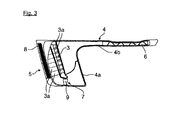
- the Fig. 3 shows in a longitudinal section, the housing 4 of the cyclone filter 3, which consists of a the cyclone filter 3 enclosing housing portion 4a and a smaller cross-sectional and rectilinear, forming a Beerberuh Trentsumble housing portion 4b, here by way of example to a, in the assembled state upper portion of the housing portion 4a connects.
- the housing section 4a has in a lateral region the inflow opening 5 covered, for example, by an inflow grate 8, and the deposition device 7 in the lower area.
- the downwardly open separation device 7 may for example be provided with a flutter valve 9, which opens under the influence of gravity for automatic separation of particles and closes by negative pressure in the intake operation.
- the outside air flows via the inflow opening 5 into the spiral channels 3a of the cyclone filter 3, which is preferably inserted into the housing 4 as a replaceable cartridge, and is set into strong rotation there in a manner known per se, particles located in the outside air being on the outside wall of the housing section 4a deposit and be discharged down to the separation device 7.
- the still turbulent outside air is supplied to the flow-calming section or the housing section 4 b and finally passed on or introduced via the outflow opening 6 located there into the air-conditioning system 2.
- the housing 4 with the cyclone filter 3, the inflow opening 5, the outflow opening 6 and the separator 7 is attached directly to the unit 2 of the air conditioner and forms with this an assembly unit, which is easily installed as a whole in the motor vehicle behind the front apron 1.
- the housing 4 with the designed as a replaceable cartridge cyclone filter 3 can be manufactured in terms of manufacturing technology simple and low weight in plastic construction.
- suction device 3 and 4 may also be positioned elsewhere in the motor vehicle, for example on a bulkhead or laterally in the engine compartment, wherein in particular the housing portion 4b of the housing 4 may be modified accordingly.
Landscapes
- Engineering & Computer Science (AREA)
- Mechanical Engineering (AREA)
- Physics & Mathematics (AREA)
- Thermal Sciences (AREA)
- Air-Conditioning For Vehicles (AREA)
- Separating Particles In Gases By Inertia (AREA)
- Filtering Of Dispersed Particles In Gases (AREA)
Abstract
Description
- Die vorliegende Erfindung betrifft eine Ansaugeinrichtung für eine Heizungs- und/oder Klimaanlage in einem Kraftfahrzeug gemäß dem Oberbegriff des Patentanspruchs 1.
- Bei Heizungs- und/oder Klimaanlagen in Kraftfahrzeugen ist es allgemein bekannt, die dem Fahrzeuginnenraum zugeführte, konditionierte Außenluft zu filtern, zumeist werden dazu plattenförmige Feinfilter verwendet. Ferner sind in der Regel stromauf dazu im Ansaugbereich der Außenluft Einströmgitter vorgesehen, die größere Gegenstände wie zum Beispiel Blätter von Pflanzen oder Bäumen, etc. von der Anlage fernhalten.
- Aufgabe der Erfindung ist es, eine Ansaugeinrichtung für eine Heizungs- und/oder Klimaanlage in Kraftfahrzeugen vorzuschlagen, die baulich einfach ausgeführt ist und die ein problemlose, sehr wirkungsvolle Vorfilterung der angesaugten Außenluft ermöglicht.
- Die Lösung dieser Aufgabe gelingt mit den Merkmalen des Patentanspruchs 1. Vorteilhafte Weiterbildungen und Ausgestaltungen der Erfindung sind in den Unteransprüchen angeführt.
- Erfindungsgemäß wird vorgeschlagen, dass der Filtereinrichtung der Heizungs- und/oder Klimaanlage ein Fliehkraftabscheider, insbesondere ein Zyklonfilter, als Vorfilter zur Abscheidung, insbesondere zur Vorabscheidung von definierten, in der Ansaugluft enthaltenen Verunreinigungen und/oder Partikeln vorgeschaltet ist. Ein derartiger Fliehkraftabscheider bzw. Zyklonfilter bewirkt dauerhaft eine zuverlässige Abscheidung von in der Außenluft enthaltenen Partikeln in fester oder flüssiger Form, wodurch sowohl die stromab liegende Filtereinrichtung, die regelmäßig als Feinfilter ausgebildet ist, geschützt als auch der Reinigungswirkungsgrad der Anlage insgesamt erhöht werden kann. Selbstverständlich kann auch dem Fliehkraftabscheider bzw. Zyklonfilter, der im Übrigen bekannter Bauart sein kann, ein Einströmgitter vorgeschaltet sein.
- Der Fliehkraftabscheider ist besonders bevorzugt in einem luftführenden Gehäuse mit wenigstens einer Einströmöffnung und mit wenigstens einer mit der Heizungs- und/oder Klimaanlage strömungsverbundenen Abströmöffnung angeordnet. Dadurch handelt es sich um ein separat handhabbares Bauteil, das entsprechend flexibel verbaut und eingesetzt werden kann. Besonders bevorzugt ist am Gehäuse zudem eine Partikel-Abscheidevorrichtung vorgesehen und/oder ausgebildet, die bevorzugt an der geodätisch tiefsten Stelle positioniert ist, an der sich schwerkraftbedingt die abgeschiedenen Partikel ablagern und von dort gegebenenfalls automatisch ausgeschieden werden können. Damit können die abgeschiedenen Verunreinigungen bzw. Partikel sehr gut und schnell aus dem Fliehkraftabscheider entfernt werden.
- Ferner kann der Fliehkraftabscheider Bestandteil einer lösbar und austauschbar gehalterten Baueinheit sein, insbesondere durch eine in das luftführende Gehäuse eingesetzte Kartusche gebildet sein. Ein derartiger Aufbau kann fertigungstechnisch günstig im Zusammenwirken mit dem umgebenden Gehäuse die spiralförmigen, die Rotation der einströmenden Außenluft bewirkenden Luftführungen bzw. Kanäle bilden.
- Physikalisch vorteilhaft ist der Fliehkraftabscheider in Einbaulage im Kraftfahrzeug bevorzugt im Wesentlichen vertikal ausgerichtet, wobei eine gegebenenfalls vorgesehene Abscheidevorrichtung dann besonders einfach und vorteilhaft an der geodätisch tiefsten Stelle positioniert werden kann.
- In einer weiteren, vorteilhaften Ausgestaltung der Erfindung kann an einem den Fliehkraft-abscheider umschließenden und die Einströmöffnung aufweisenden Gehäuseabschnitt des Gehäuses ein die Ausströmöffnung aufweisender Gehäuseabschnitt geringeren Querschnitts als Luftberuhigungsstrecke angeschlossen sein. Daraus resultiert eine Strömungsberuhigung der Außenluft mit die Luftförderung der Heizungs- und/oder Klimaanlage nur unwesentlich beeinträchtigendem Strömungswiderstand.
- Des Weiteren wird vorgeschlagen, dass der Fliehkraftabscheider oder ein den Fliehkraftabscheider aufnehmendes luftführendes Gehäuse hinter oder vor einem Frontverkleidungsteil eines Fahrzeugs, insbesondere hinter einer Bugschürze eines Kraftfahrzeugs, angeordnet ist. Dies stellt eine besonders günstige, gegebenenfalls durch den Fahrtwind eines Kraftfahrzeugs unterstützte Einströmung der Umgebungs- bzw. Außenluft sicher.
- In einer vorteilhaften Ausgestaltung der Erfindung können des Weiteren der Fliehkraft-abscheider bzw. Zyktonfilter und das luftführende Gehäuse unmittelbar an eine Bauteile der Heizungs- und/oder Klimaanlage aufnehmende Baueinheit angebaut sein und somit als eine Montageeinheit im Kraftfahrzeug verbaut werden. Schließlich kann auch diese Baueinheit der Heizungs- und/oder Klimaanlage gemäß einer bevorzugten Ausgestaltung hinter der Bugschürze eines Kraftfahrzeugs angeordnet sein, so dass das luftführende Gehäuse mit dem Fliehkraftabscheider unmittelbar an die Baueinheit angebaut ist und/oder mit diesem eine Montageinheit bildet.
- Ein Ausführungsbeispiel der Erfindung ist im Folgenden mit weiteren Einzelheiten näher beschrieben.
- Es zeigen:
-
Fig. 1 in skizzenhafter Darstellung eine Frontansicht auf eine hinter einer Bugschürze eines Nutzkraftfahrzeugs angeordnete Klimaanlage mit einer Ansaugeinrichtung für Außenluft und einem in einem Luftführungsgehäuse angeordneten Zyklonfilter als Fliehkraftabscheider; -
Fig. 2 eine Ansicht von schräg vorne auf die Ansaugeinrichtung mit dem Zyklonfilter und dem Kasten der Klimaanlage nachFig. 1 ; und -
Fig. 3 einen Längsschnitt durch die Ansaugeinrichtung gemäß denFig. 1 und 2 mit dem Zyklonfilter und dem diesen umgebenden Gehäuse. - In den
Fig. 1 und 2 ist eine nur angedeutete Bugschürze 1 eines nicht weiter dargestellten Nutzkraftfahrzeugs bezeichnet, hinter der eine Bauteile einer Klima- und/oder Heizungsanlage tragende Baueinheit 2 angeordnet ist. - In der Baueinheit 2 können zum Beispiel ein elektrisches Gebläse, ein Wärmetauscher, ein Verdampfer, ein Feinfilter, Luftleitelemente, etc. angeordnet sein, über die einem Fahrzeuginnenraum gefilterte und konditionierte Außenluft zuführbar ist.
- Der Baueinheit 2 bzw. der Heizungs- und/oder Klimaanlage vorgeschaltet ist als Ansaugeinrichtung ein Zyklonfilter 3 mit einem diesen umgebenden Gehäuse 4.
- Das Gehäuse 4 weist eine Einströmöffnung (bei 5), eine mit der Klimaanlage luftführend verbundene Abströmöffnung (bei 6) und eine Abscheidevorrichtung 7 auf, wobei, wie ersichtlich, die Abscheidevorrichtung 7 an der geodätisch tiefsten Stelle des vertikal ausgerichteten Zyklonfilters 3 positioniert ist.
- Die
Fig. 3 zeigt in einem Längsschnitt das Gehäuse 4 des Zyklonfilters 3, das sich aus einem den Zyklonfilter 3 umschließenden Gehäuseabschnitt 4a und einem im Querschnitt geringerem und geradlinigen, eine Luftberuhigungsstrecke bildenden Gehäuseabschnitt 4b zusammensetzt, das sich hier beispielhaft an einen, im montierten Zustand oberen Bereich des Gehäuseabschnitts 4a anschließt. - Dabei weist der Gehäuseabschnitt 4a in einem seitlichen Bereich die zum Beispiel durch ein Einströmgitter 8 abgedeckte Einströmöffnung 5 und im unteren Bereich die Abscheidevorrichtung 7 auf. Die nach unten offene Abscheidevorrichtung 7 kann zum Beispiel mit einem Flatterventil 9 versehen sein, das unter Schwerkrafteinfluss zur automatischen Abscheidung von Partikeln öffnet und durch Unterdruck im Ansaugbetrieb schließt.
- Über die Einströmöffnung 5 strömt die Außenluft in die spiralförmigen Kanäle 3a des bevorzugt als austauschbare Kartusche in das Gehäuse 4 eingesetzten Zyklonfilters 3 ein und wird dort in an sich bekannter Weise in starke Rotation versetzt, wobei sich in der Außenluft befindliche Partikel an der Außenwand des Gehäuseabschnitts 4a ablagern und nach unten zur Abscheidevorrichtung 7 abgeführt werden.
- Von dem Gehäuseabschnitt 4a aus wird die noch turbulente Außenluft der strömungsberuhigenden Strecke bzw. dem Gehäuseabschnitt 4b zugeführt und schließlich über die dort befindliche Ausströmöffnung 6 in die Klimaanlage 2 weiter- bzw. eingeleitet.
- Das Gehäuse 4 mit dem Zyklonfilter 3, der Einströmöffnung 5, der Ausströmöffnung 6 und der Abscheidevorrichtung 7 ist an die Baueinheit 2 der Klimaanlage unmittelbar angebaut und bildet mit dieser eine Montageeinheit, die als Ganzes einfach in das Kraftfahrzeug hinter dessen Bugschürze 1 einbaubar ist.
- Das Gehäuse 4 mit dem als austauschbare Kartusche ausgebildeten Zyklonfilter 3 kann fertigungstechnisch einfach und gewichtsgünstig in Kunststoffbauweise hergestellt sein.
- Abweichend von der beschriebenen Anordnung der Ansaugeinrichtung 3 und 4 kann diese auch an anderer Stelle des Kraftfahrzeugs positioniert sein, zum Beispiel an einer Spritzwand oder seitlich im Motorraum, wobei insbesondere der Gehäuseabschnitt 4b des Gehäuses 4 entsprechend modifiziert sein kann.
-
- 1
- Bugschürze
- 2
- Kasten Klimaanlage
- 3
- Zyklonfilter
- 3a
- Spiralkanäle
- 4
- Gehäuse
- 4a
- Gehäuseabschnitt
- 4b
- Gehäuseabschnitt
- 5
- Einströmöffnung
- 6
- Ausströmöffnung
- 7
- Abscheidevorrichtung
- 8
- Einströmgitter
- 9
- Flatterventil
Claims (10)
- Ansaugeinrichtung für eine Heizungs- und/oder Klimaanlage in einem Kraftfahrzeug, insbesondere in einem Nutzfahrzeug, die über wenigstens eine luftführende Leitung Ansaugluft, insbesondere Außen- und/oder Umgebungsluft, ansaugt und über eine Filtereinrichtung dem Fahrzeuginnenraum als gefilterte Luft zuführt, dadurch gekennzeichnet, dass der Filtereinrichtung der Heizungs- und/oder Klimaanlage (2) ein Fliehkraftabscheider (3), insbesondere ein Zyklonfilter, als Vorfilter zur Abscheidung, insbesondere zur Vorabscheidung, von in der Ansaugluft enthaltenen Verunreinigungen und/oder Partikeln vorgeschaltet ist.
- Ansaugeinrichtung nach Anspruch 1, dadurch gekennzeichnet, dass der Fliehkraft-abscheider (3) in einem luftführenden Gehäuse (4) mit wenigstens einer Einströmöffnung (5) und mit wenigstens einer mit der Heizungs- und/oder Klimaanlage strömungsverbundenen Abströmöffnung (6) angeordnet ist.
- Ansaugeinrichtung nach Anspruch 2, dadurch gekennzeichnet, dass am Gehäuse (4) einer Partikel-Abscheidevorrichtung (7) ausgebildet und/oder angeordnet ist, wobei bevorzugt vorgesehen ist, dass die Abscheidevorrichtung (7) an der geodätisch tiefsten Stelle positioniert ist.
- Ansaugeinrichtung nach einem der vorhergehenden Ansprüche, dadurch gekennzeichnet, dass der Fliehkraftabscheider (3) Bestandteil einer lösbar und austauschbar gehalterten Baueinheit ist, insbesondere durch eine in das luftführende Gehäuse (4a) eingesetzte Kartusche gebildet ist.
- Ansaugeinrichtung nach einem der vorhergehenden Ansprüche, dadurch gekennzeichnet, dass der Fliehkraftabscheider (3) in seiner Einbaulage im Fahrzeug im Wesentlichen vertikal ausgerichtet ist.
- Ansaugeinrichtung nach einem der Ansprüche 2 bis 5, dadurch gekennzeichnet, dass an einem den Fliehkraftabscheider (3) umschließenden und die Einströmöffnung (5) aufweisenden Gehäuseabschnitt (4a) des Gehäuses (4) ein die Ausströmöffnung (6) aufweisender Gehäuseabschnitt (4b) geringeren Querschnitts als Luftberuhigungsstrecke angeschlossen ist.
- Ansaugeinrichtung nach einem der vorhergehenden Ansprüche, dadurch gekennzeichnet, dass der Fliehkraftabscheider (3) oder ein den Fliehkraftabscheider (3) aufnehmendes luftführendes Gehäuse (4) hinter oder vor einem Frontverkleidungsteil eines Fahrzeugs, insbesondere hinter oder vor einer Bugschürze (1) eines Kraftfahrzeugs, angeordnet ist.
- Ansaugeinrichtung nach einem der Ansprüche 2 bis 7, dadurch gekennzeichnet, dass der Fliehkraftabscheider (3) und das luftführende Gehäuse (4) unmittelbar an eine, Bauteile der Heizungs- und/oder Klimaanlage aufnehmende Baueinheit (2) angebaut sind.
- Ansaugeinrichtung nach Anspruch 7 und 8, dadurch gekennzeichnet, dass die Baueinheit (2) der Heizungs- und/oder Klimaanlage hinter der Bugschürze (1) des Kraftfahrzeugs angeordnet ist und dass das luftführende Gehäuse (4) mit dem Fliehkraftabscheider (3) unmittelbar an die Baueinheit (2) angebaut ist und/oder mit diesem eine Montageinheit bildet.
- Kraftfahrzeug, insbesondere Nutzfahrzeug, mit einer Ansaugeinrichtung nach einem der vorhergehenden Ansprüche.
Applications Claiming Priority (1)
| Application Number | Priority Date | Filing Date | Title |
|---|---|---|---|
| DE102012018729.7A DE102012018729A1 (de) | 2012-09-21 | 2012-09-21 | Ansaugeinrichtung für eine Heizungs- und/oder Klimaanlage in einem Kraftfahrzeug, insbesondere in einem Nutzfahrzeug |
Publications (3)
| Publication Number | Publication Date |
|---|---|
| EP2711216A2 true EP2711216A2 (de) | 2014-03-26 |
| EP2711216A3 EP2711216A3 (de) | 2014-07-02 |
| EP2711216B1 EP2711216B1 (de) | 2020-03-18 |
Family
ID=48184005
Family Applications (1)
| Application Number | Title | Priority Date | Filing Date |
|---|---|---|---|
| EP13002064.7A Active EP2711216B1 (de) | 2012-09-21 | 2013-04-19 | Ansaugeinrichtung für eine Heizungs- und/oder Klimaanlage in einem Kraftfahrzeug, insbesondere in einem Nutzfahrzeug |
Country Status (2)
| Country | Link |
|---|---|
| EP (1) | EP2711216B1 (de) |
| DE (1) | DE102012018729A1 (de) |
Cited By (1)
| Publication number | Priority date | Publication date | Assignee | Title |
|---|---|---|---|---|
| FR3161471A1 (fr) | 2024-04-22 | 2025-10-24 | Renault Sas | Dispositif de ventilation pour véhicule automobile comportant un module de recyclage d’air |
Families Citing this family (1)
| Publication number | Priority date | Publication date | Assignee | Title |
|---|---|---|---|---|
| EP4260930A1 (de) * | 2022-04-13 | 2023-10-18 | MANN+HUMMEL GmbH | Kabinenluftfiltersystem für ein fahrzeug und verfahren zur reinigung der einer kabine zuzuführenden luft |
Family Cites Families (4)
| Publication number | Priority date | Publication date | Assignee | Title |
|---|---|---|---|---|
| DE1808206U (de) * | 1960-01-13 | 1960-03-17 | Anton Schneider | Schutzanordnung fuer die eintrittsoeffnung des frischluftkanals bei klimaanlagen fuer fahrzeuge. |
| EP0125620A1 (de) * | 1983-05-16 | 1984-11-21 | Deere & Company | Luftfiltersystem |
| US4531453A (en) * | 1983-05-16 | 1985-07-30 | Deere & Company | Atmosphere control arrangement for an operator enclosure |
| FR2870787B1 (fr) * | 2004-05-28 | 2008-09-12 | Renault Sas | Dispositif d'entree d'air et capot de vehicule |
-
2012
- 2012-09-21 DE DE102012018729.7A patent/DE102012018729A1/de not_active Withdrawn
-
2013
- 2013-04-19 EP EP13002064.7A patent/EP2711216B1/de active Active
Non-Patent Citations (1)
| Title |
|---|
| None |
Cited By (1)
| Publication number | Priority date | Publication date | Assignee | Title |
|---|---|---|---|---|
| FR3161471A1 (fr) | 2024-04-22 | 2025-10-24 | Renault Sas | Dispositif de ventilation pour véhicule automobile comportant un module de recyclage d’air |
Also Published As
| Publication number | Publication date |
|---|---|
| DE102012018729A1 (de) | 2014-03-27 |
| EP2711216A3 (de) | 2014-07-02 |
| EP2711216B1 (de) | 2020-03-18 |
Similar Documents
| Publication | Publication Date | Title |
|---|---|---|
| DE102011110696B4 (de) | Lufthutzen-Zyklonfilteranordnung | |
| DE102011016893B4 (de) | Ölabscheider zur Abscheidung wenigstens von Öl aus einem Aerosol | |
| DE102017007326A1 (de) | Multizyklonabscheider eines Mehrstufen-Fluidfilters zur Reinigung von gasförmigem Fluid und Mehrstufen-Fluidfilter | |
| DE102010055441A1 (de) | Luftfilter für ein Kraftfahrzeug | |
| DE102004036083B4 (de) | Ansaugvorrichtung | |
| EP2594462B1 (de) | Wasserkasten für ein Kraftfahrzeug | |
| EP1364696B1 (de) | Vorrichtung zur Reinigung eines Gasstromes | |
| DE102004055259B3 (de) | Luftzuführeinrichtung für die Fahrgastzelle eines Kraftfahrzeugs | |
| EP1496240A2 (de) | Abscheidesystem | |
| DE102015109999A1 (de) | Luftfilteranlage | |
| EP3291908B1 (de) | Abscheidevorrichtung zum abscheiden von partikeln aus einem luftstrom | |
| EP2711216B1 (de) | Ansaugeinrichtung für eine Heizungs- und/oder Klimaanlage in einem Kraftfahrzeug, insbesondere in einem Nutzfahrzeug | |
| EP2423496B1 (de) | Zyklonabscheider mit horizontaler Zyklonachse | |
| DE10209132B4 (de) | Ansaugvorrichtung für Kaltluft | |
| DE102008064344B4 (de) | Scheinwerfer eines Kraftfahrzeugs | |
| DE112014004379B4 (de) | Anordnung zum Absaugen von in einem Luftreiniger eingefangenen Partikeln und ein Kraftfahrzeug, das eine solche Anordnung umfasst | |
| EP1626645A1 (de) | Vorrichtung zum entfernen von teilchen aus einem abscheideraum | |
| EP0125620A1 (de) | Luftfiltersystem | |
| DE102008061538A1 (de) | Kanalanordnung zum Führen von Prozessluft zu einer Verbrennungskraftmaschine | |
| DE102013018166B4 (de) | Filtersystem mit Wasserauslassöffnung | |
| WO2016173856A1 (de) | Vorrichtung zum filtern von luft | |
| DE102015005297A1 (de) | Filtervorrichtung für ein Kraftfahrzeug-Luftführungssystem | |
| EP3786458A1 (de) | Lüfterhutze für ein fahrzeugsystem | |
| DE102016204391A1 (de) | Heizungs-, Belüftungs- oder Klimaanlage | |
| DE102006039647A1 (de) | Partikelabscheider |
Legal Events
| Date | Code | Title | Description |
|---|---|---|---|
| PUAI | Public reference made under article 153(3) epc to a published international application that has entered the european phase |
Free format text: ORIGINAL CODE: 0009012 |
|
| AK | Designated contracting states |
Kind code of ref document: A2 Designated state(s): AL AT BE BG CH CY CZ DE DK EE ES FI FR GB GR HR HU IE IS IT LI LT LU LV MC MK MT NL NO PL PT RO RS SE SI SK SM TR |
|
| AX | Request for extension of the european patent |
Extension state: BA ME |
|
| PUAL | Search report despatched |
Free format text: ORIGINAL CODE: 0009013 |
|
| AK | Designated contracting states |
Kind code of ref document: A3 Designated state(s): AL AT BE BG CH CY CZ DE DK EE ES FI FR GB GR HR HU IE IS IT LI LT LU LV MC MK MT NL NO PL PT RO RS SE SI SK SM TR |
|
| AX | Request for extension of the european patent |
Extension state: BA ME |
|
| RIC1 | Information provided on ipc code assigned before grant |
Ipc: B60H 1/26 20060101ALI20140528BHEP Ipc: B60H 1/00 20060101AFI20140528BHEP Ipc: B60H 3/06 20060101ALI20140528BHEP |
|
| 17P | Request for examination filed |
Effective date: 20140626 |
|
| STAA | Information on the status of an ep patent application or granted ep patent |
Free format text: STATUS: EXAMINATION IS IN PROGRESS |
|
| 17Q | First examination report despatched |
Effective date: 20170403 |
|
| RAP1 | Party data changed (applicant data changed or rights of an application transferred) |
Owner name: MAN TRUCK & BUS SE |
|
| GRAP | Despatch of communication of intention to grant a patent |
Free format text: ORIGINAL CODE: EPIDOSNIGR1 |
|
| STAA | Information on the status of an ep patent application or granted ep patent |
Free format text: STATUS: GRANT OF PATENT IS INTENDED |
|
| INTG | Intention to grant announced |
Effective date: 20191009 |
|
| GRAS | Grant fee paid |
Free format text: ORIGINAL CODE: EPIDOSNIGR3 |
|
| GRAA | (expected) grant |
Free format text: ORIGINAL CODE: 0009210 |
|
| STAA | Information on the status of an ep patent application or granted ep patent |
Free format text: STATUS: THE PATENT HAS BEEN GRANTED |
|
| AK | Designated contracting states |
Kind code of ref document: B1 Designated state(s): AL AT BE BG CH CY CZ DE DK EE ES FI FR GB GR HR HU IE IS IT LI LT LU LV MC MK MT NL NO PL PT RO RS SE SI SK SM TR |
|
| REG | Reference to a national code |
Ref country code: GB Ref legal event code: FG4D Free format text: NOT ENGLISH |
|
| REG | Reference to a national code |
Ref country code: DE Ref legal event code: R096 Ref document number: 502013014441 Country of ref document: DE |
|
| REG | Reference to a national code |
Ref country code: AT Ref legal event code: REF Ref document number: 1245514 Country of ref document: AT Kind code of ref document: T Effective date: 20200415 Ref country code: IE Ref legal event code: FG4D Free format text: LANGUAGE OF EP DOCUMENT: GERMAN |
|
| REG | Reference to a national code |
Ref country code: NL Ref legal event code: FP |
|
| REG | Reference to a national code |
Ref country code: SE Ref legal event code: TRGR |
|
| PG25 | Lapsed in a contracting state [announced via postgrant information from national office to epo] |
Ref country code: NO Free format text: LAPSE BECAUSE OF FAILURE TO SUBMIT A TRANSLATION OF THE DESCRIPTION OR TO PAY THE FEE WITHIN THE PRESCRIBED TIME-LIMIT Effective date: 20200618 Ref country code: FI Free format text: LAPSE BECAUSE OF FAILURE TO SUBMIT A TRANSLATION OF THE DESCRIPTION OR TO PAY THE FEE WITHIN THE PRESCRIBED TIME-LIMIT Effective date: 20200318 Ref country code: RS Free format text: LAPSE BECAUSE OF FAILURE TO SUBMIT A TRANSLATION OF THE DESCRIPTION OR TO PAY THE FEE WITHIN THE PRESCRIBED TIME-LIMIT Effective date: 20200318 |
|
| PG25 | Lapsed in a contracting state [announced via postgrant information from national office to epo] |
Ref country code: GR Free format text: LAPSE BECAUSE OF FAILURE TO SUBMIT A TRANSLATION OF THE DESCRIPTION OR TO PAY THE FEE WITHIN THE PRESCRIBED TIME-LIMIT Effective date: 20200619 Ref country code: HR Free format text: LAPSE BECAUSE OF FAILURE TO SUBMIT A TRANSLATION OF THE DESCRIPTION OR TO PAY THE FEE WITHIN THE PRESCRIBED TIME-LIMIT Effective date: 20200318 Ref country code: BG Free format text: LAPSE BECAUSE OF FAILURE TO SUBMIT A TRANSLATION OF THE DESCRIPTION OR TO PAY THE FEE WITHIN THE PRESCRIBED TIME-LIMIT Effective date: 20200618 Ref country code: LV Free format text: LAPSE BECAUSE OF FAILURE TO SUBMIT A TRANSLATION OF THE DESCRIPTION OR TO PAY THE FEE WITHIN THE PRESCRIBED TIME-LIMIT Effective date: 20200318 |
|
| REG | Reference to a national code |
Ref country code: LT Ref legal event code: MG4D |
|
| PG25 | Lapsed in a contracting state [announced via postgrant information from national office to epo] |
Ref country code: PT Free format text: LAPSE BECAUSE OF FAILURE TO SUBMIT A TRANSLATION OF THE DESCRIPTION OR TO PAY THE FEE WITHIN THE PRESCRIBED TIME-LIMIT Effective date: 20200812 Ref country code: LT Free format text: LAPSE BECAUSE OF FAILURE TO SUBMIT A TRANSLATION OF THE DESCRIPTION OR TO PAY THE FEE WITHIN THE PRESCRIBED TIME-LIMIT Effective date: 20200318 Ref country code: EE Free format text: LAPSE BECAUSE OF FAILURE TO SUBMIT A TRANSLATION OF THE DESCRIPTION OR TO PAY THE FEE WITHIN THE PRESCRIBED TIME-LIMIT Effective date: 20200318 Ref country code: SM Free format text: LAPSE BECAUSE OF FAILURE TO SUBMIT A TRANSLATION OF THE DESCRIPTION OR TO PAY THE FEE WITHIN THE PRESCRIBED TIME-LIMIT Effective date: 20200318 Ref country code: IS Free format text: LAPSE BECAUSE OF FAILURE TO SUBMIT A TRANSLATION OF THE DESCRIPTION OR TO PAY THE FEE WITHIN THE PRESCRIBED TIME-LIMIT Effective date: 20200718 Ref country code: RO Free format text: LAPSE BECAUSE OF FAILURE TO SUBMIT A TRANSLATION OF THE DESCRIPTION OR TO PAY THE FEE WITHIN THE PRESCRIBED TIME-LIMIT Effective date: 20200318 Ref country code: CZ Free format text: LAPSE BECAUSE OF FAILURE TO SUBMIT A TRANSLATION OF THE DESCRIPTION OR TO PAY THE FEE WITHIN THE PRESCRIBED TIME-LIMIT Effective date: 20200318 Ref country code: SK Free format text: LAPSE BECAUSE OF FAILURE TO SUBMIT A TRANSLATION OF THE DESCRIPTION OR TO PAY THE FEE WITHIN THE PRESCRIBED TIME-LIMIT Effective date: 20200318 |
|
| REG | Reference to a national code |
Ref country code: CH Ref legal event code: PL |
|
| REG | Reference to a national code |
Ref country code: DE Ref legal event code: R097 Ref document number: 502013014441 Country of ref document: DE |
|
| PG25 | Lapsed in a contracting state [announced via postgrant information from national office to epo] |
Ref country code: MC Free format text: LAPSE BECAUSE OF FAILURE TO SUBMIT A TRANSLATION OF THE DESCRIPTION OR TO PAY THE FEE WITHIN THE PRESCRIBED TIME-LIMIT Effective date: 20200318 |
|
| PLBE | No opposition filed within time limit |
Free format text: ORIGINAL CODE: 0009261 |
|
| STAA | Information on the status of an ep patent application or granted ep patent |
Free format text: STATUS: NO OPPOSITION FILED WITHIN TIME LIMIT |
|
| PG25 | Lapsed in a contracting state [announced via postgrant information from national office to epo] |
Ref country code: LI Free format text: LAPSE BECAUSE OF NON-PAYMENT OF DUE FEES Effective date: 20200430 Ref country code: ES Free format text: LAPSE BECAUSE OF FAILURE TO SUBMIT A TRANSLATION OF THE DESCRIPTION OR TO PAY THE FEE WITHIN THE PRESCRIBED TIME-LIMIT Effective date: 20200318 Ref country code: LU Free format text: LAPSE BECAUSE OF NON-PAYMENT OF DUE FEES Effective date: 20200419 Ref country code: DK Free format text: LAPSE BECAUSE OF FAILURE TO SUBMIT A TRANSLATION OF THE DESCRIPTION OR TO PAY THE FEE WITHIN THE PRESCRIBED TIME-LIMIT Effective date: 20200318 Ref country code: CH Free format text: LAPSE BECAUSE OF NON-PAYMENT OF DUE FEES Effective date: 20200430 |
|
| REG | Reference to a national code |
Ref country code: BE Ref legal event code: MM Effective date: 20200430 |
|
| 26N | No opposition filed |
Effective date: 20201221 |
|
| PG25 | Lapsed in a contracting state [announced via postgrant information from national office to epo] |
Ref country code: BE Free format text: LAPSE BECAUSE OF NON-PAYMENT OF DUE FEES Effective date: 20200430 Ref country code: PL Free format text: LAPSE BECAUSE OF FAILURE TO SUBMIT A TRANSLATION OF THE DESCRIPTION OR TO PAY THE FEE WITHIN THE PRESCRIBED TIME-LIMIT Effective date: 20200318 |
|
| GBPC | Gb: european patent ceased through non-payment of renewal fee |
Effective date: 20200618 |
|
| PG25 | Lapsed in a contracting state [announced via postgrant information from national office to epo] |
Ref country code: IE Free format text: LAPSE BECAUSE OF NON-PAYMENT OF DUE FEES Effective date: 20200419 Ref country code: GB Free format text: LAPSE BECAUSE OF NON-PAYMENT OF DUE FEES Effective date: 20200618 |
|
| PG25 | Lapsed in a contracting state [announced via postgrant information from national office to epo] |
Ref country code: SI Free format text: LAPSE BECAUSE OF FAILURE TO SUBMIT A TRANSLATION OF THE DESCRIPTION OR TO PAY THE FEE WITHIN THE PRESCRIBED TIME-LIMIT Effective date: 20200318 |
|
| REG | Reference to a national code |
Ref country code: AT Ref legal event code: MM01 Ref document number: 1245514 Country of ref document: AT Kind code of ref document: T Effective date: 20200419 |
|
| PG25 | Lapsed in a contracting state [announced via postgrant information from national office to epo] |
Ref country code: AT Free format text: LAPSE BECAUSE OF NON-PAYMENT OF DUE FEES Effective date: 20200419 |
|
| PG25 | Lapsed in a contracting state [announced via postgrant information from national office to epo] |
Ref country code: TR Free format text: LAPSE BECAUSE OF FAILURE TO SUBMIT A TRANSLATION OF THE DESCRIPTION OR TO PAY THE FEE WITHIN THE PRESCRIBED TIME-LIMIT Effective date: 20200318 Ref country code: MT Free format text: LAPSE BECAUSE OF FAILURE TO SUBMIT A TRANSLATION OF THE DESCRIPTION OR TO PAY THE FEE WITHIN THE PRESCRIBED TIME-LIMIT Effective date: 20200318 Ref country code: CY Free format text: LAPSE BECAUSE OF FAILURE TO SUBMIT A TRANSLATION OF THE DESCRIPTION OR TO PAY THE FEE WITHIN THE PRESCRIBED TIME-LIMIT Effective date: 20200318 |
|
| PG25 | Lapsed in a contracting state [announced via postgrant information from national office to epo] |
Ref country code: MK Free format text: LAPSE BECAUSE OF FAILURE TO SUBMIT A TRANSLATION OF THE DESCRIPTION OR TO PAY THE FEE WITHIN THE PRESCRIBED TIME-LIMIT Effective date: 20200318 Ref country code: AL Free format text: LAPSE BECAUSE OF FAILURE TO SUBMIT A TRANSLATION OF THE DESCRIPTION OR TO PAY THE FEE WITHIN THE PRESCRIBED TIME-LIMIT Effective date: 20200318 |
|
| PGFP | Annual fee paid to national office [announced via postgrant information from national office to epo] |
Ref country code: NL Payment date: 20250424 Year of fee payment: 13 |
|
| PGFP | Annual fee paid to national office [announced via postgrant information from national office to epo] |
Ref country code: DE Payment date: 20250428 Year of fee payment: 13 |
|
| PGFP | Annual fee paid to national office [announced via postgrant information from national office to epo] |
Ref country code: IT Payment date: 20250422 Year of fee payment: 13 |
|
| PGFP | Annual fee paid to national office [announced via postgrant information from national office to epo] |
Ref country code: FR Payment date: 20250424 Year of fee payment: 13 |
|
| PGFP | Annual fee paid to national office [announced via postgrant information from national office to epo] |
Ref country code: SE Payment date: 20250424 Year of fee payment: 13 |