EP2711209B1 - Mounting arrangement for a trailer coupling or a load bearer from a sheet metal panel - Google Patents
Mounting arrangement for a trailer coupling or a load bearer from a sheet metal panel Download PDFInfo
- Publication number
- EP2711209B1 EP2711209B1 EP13004437.3A EP13004437A EP2711209B1 EP 2711209 B1 EP2711209 B1 EP 2711209B1 EP 13004437 A EP13004437 A EP 13004437A EP 2711209 B1 EP2711209 B1 EP 2711209B1
- Authority
- EP
- European Patent Office
- Prior art keywords
- cross
- base body
- support assembly
- sheet metal
- assembly according
- Prior art date
- Legal status (The legal status is an assumption and is not a legal conclusion. Google has not performed a legal analysis and makes no representation as to the accuracy of the status listed.)
- Active
Links
- 238000010168 coupling process Methods 0.000 title claims description 62
- 238000005859 coupling reaction Methods 0.000 title claims description 62
- 230000008878 coupling Effects 0.000 title claims description 61
- 239000002184 metal Substances 0.000 title claims description 50
- 229910052751 metal Inorganic materials 0.000 title claims description 50
- 239000000835 fiber Substances 0.000 claims description 45
- 230000003014 reinforcing effect Effects 0.000 claims description 27
- 239000000853 adhesive Substances 0.000 claims description 17
- 230000001070 adhesive effect Effects 0.000 claims description 17
- 238000004519 manufacturing process Methods 0.000 claims description 12
- 239000000463 material Substances 0.000 claims description 12
- 238000000034 method Methods 0.000 claims description 7
- 238000005520 cutting process Methods 0.000 claims description 6
- 239000004744 fabric Substances 0.000 claims description 5
- 238000003466 welding Methods 0.000 claims description 4
- 239000002759 woven fabric Substances 0.000 claims description 3
- 239000013585 weight reducing agent Substances 0.000 claims description 2
- 238000006243 chemical reaction Methods 0.000 claims 5
- 239000002994 raw material Substances 0.000 claims 1
- 239000002657 fibrous material Substances 0.000 description 63
- 230000002787 reinforcement Effects 0.000 description 32
- 238000010438 heat treatment Methods 0.000 description 12
- 238000003825 pressing Methods 0.000 description 12
- 239000011159 matrix material Substances 0.000 description 9
- 229910000831 Steel Inorganic materials 0.000 description 7
- 239000010410 layer Substances 0.000 description 7
- 239000010959 steel Substances 0.000 description 7
- 239000000969 carrier Substances 0.000 description 6
- 238000010276 construction Methods 0.000 description 6
- 239000004033 plastic Substances 0.000 description 6
- 230000008901 benefit Effects 0.000 description 5
- 239000002131 composite material Substances 0.000 description 5
- 229910000712 Boron steel Inorganic materials 0.000 description 4
- 238000004026 adhesive bonding Methods 0.000 description 4
- 239000011324 bead Substances 0.000 description 4
- 239000011248 coating agent Substances 0.000 description 4
- 238000000576 coating method Methods 0.000 description 4
- 238000001816 cooling Methods 0.000 description 4
- 230000000694 effects Effects 0.000 description 4
- 230000036961 partial effect Effects 0.000 description 4
- 239000011265 semifinished product Substances 0.000 description 4
- 230000000712 assembly Effects 0.000 description 3
- 238000000429 assembly Methods 0.000 description 3
- 239000006260 foam Substances 0.000 description 3
- 230000008569 process Effects 0.000 description 3
- 238000004080 punching Methods 0.000 description 3
- 238000007789 sealing Methods 0.000 description 3
- 238000000926 separation method Methods 0.000 description 3
- 229920001169 thermoplastic Polymers 0.000 description 3
- 229920001187 thermosetting polymer Polymers 0.000 description 3
- 239000004416 thermosoftening plastic Substances 0.000 description 3
- 244000198134 Agave sisalana Species 0.000 description 2
- 229920000049 Carbon (fiber) Polymers 0.000 description 2
- 244000060011 Cocos nucifera Species 0.000 description 2
- 235000013162 Cocos nucifera Nutrition 0.000 description 2
- 229910052782 aluminium Inorganic materials 0.000 description 2
- XAGFODPZIPBFFR-UHFFFAOYSA-N aluminium Chemical compound [Al] XAGFODPZIPBFFR-UHFFFAOYSA-N 0.000 description 2
- 239000004760 aramid Substances 0.000 description 2
- 229920006231 aramid fiber Polymers 0.000 description 2
- 230000015572 biosynthetic process Effects 0.000 description 2
- 239000004917 carbon fiber Substances 0.000 description 2
- 238000002485 combustion reaction Methods 0.000 description 2
- 230000000295 complement effect Effects 0.000 description 2
- 238000005755 formation reaction Methods 0.000 description 2
- 238000005246 galvanizing Methods 0.000 description 2
- 239000003365 glass fiber Substances 0.000 description 2
- 238000003698 laser cutting Methods 0.000 description 2
- 230000000149 penetrating effect Effects 0.000 description 2
- 229920000642 polymer Polymers 0.000 description 2
- 239000000047 product Substances 0.000 description 2
- 238000004064 recycling Methods 0.000 description 2
- 230000002829 reductive effect Effects 0.000 description 2
- 238000007493 shaping process Methods 0.000 description 2
- 230000007704 transition Effects 0.000 description 2
- 229910000789 Aluminium-silicon alloy Inorganic materials 0.000 description 1
- 244000025254 Cannabis sativa Species 0.000 description 1
- 235000012766 Cannabis sativa ssp. sativa var. sativa Nutrition 0.000 description 1
- 235000012765 Cannabis sativa ssp. sativa var. spontanea Nutrition 0.000 description 1
- 240000000491 Corchorus aestuans Species 0.000 description 1
- 235000011777 Corchorus aestuans Nutrition 0.000 description 1
- 235000010862 Corchorus capsularis Nutrition 0.000 description 1
- 235000004431 Linum usitatissimum Nutrition 0.000 description 1
- 240000006240 Linum usitatissimum Species 0.000 description 1
- 229910000617 Mangalloy Inorganic materials 0.000 description 1
- 238000010521 absorption reaction Methods 0.000 description 1
- CSDREXVUYHZDNP-UHFFFAOYSA-N alumanylidynesilicon Chemical compound [Al].[Si] CSDREXVUYHZDNP-UHFFFAOYSA-N 0.000 description 1
- PALQHNLJJQMCIQ-UHFFFAOYSA-N boron;manganese Chemical compound [Mn]#B PALQHNLJJQMCIQ-UHFFFAOYSA-N 0.000 description 1
- 235000009120 camo Nutrition 0.000 description 1
- 235000005607 chanvre indien Nutrition 0.000 description 1
- 238000005260 corrosion Methods 0.000 description 1
- 230000007797 corrosion Effects 0.000 description 1
- 238000003618 dip coating Methods 0.000 description 1
- 238000004049 embossing Methods 0.000 description 1
- 230000007613 environmental effect Effects 0.000 description 1
- 238000001125 extrusion Methods 0.000 description 1
- 239000000446 fuel Substances 0.000 description 1
- 239000003292 glue Substances 0.000 description 1
- 239000011487 hemp Substances 0.000 description 1
- 230000001771 impaired effect Effects 0.000 description 1
- 230000002401 inhibitory effect Effects 0.000 description 1
- 239000007788 liquid Substances 0.000 description 1
- 239000007769 metal material Substances 0.000 description 1
- 239000004745 nonwoven fabric Substances 0.000 description 1
- 238000005457 optimization Methods 0.000 description 1
- 239000011368 organic material Substances 0.000 description 1
- 230000003647 oxidation Effects 0.000 description 1
- 238000007254 oxidation reaction Methods 0.000 description 1
- 238000012805 post-processing Methods 0.000 description 1
- 238000012545 processing Methods 0.000 description 1
- 239000011241 protective layer Substances 0.000 description 1
- 238000010791 quenching Methods 0.000 description 1
- 230000000171 quenching effect Effects 0.000 description 1
- 230000009467 reduction Effects 0.000 description 1
- 239000011347 resin Substances 0.000 description 1
- 229920005989 resin Polymers 0.000 description 1
- 239000003351 stiffener Substances 0.000 description 1
- 239000012815 thermoplastic material Substances 0.000 description 1
- 239000002966 varnish Substances 0.000 description 1
- 230000003313 weakening effect Effects 0.000 description 1
Images

Classifications
-
- B—PERFORMING OPERATIONS; TRANSPORTING
- B60—VEHICLES IN GENERAL
- B60D—VEHICLE CONNECTIONS
- B60D1/00—Traction couplings; Hitches; Draw-gear; Towing devices
- B60D1/48—Traction couplings; Hitches; Draw-gear; Towing devices characterised by the mounting
- B60D1/485—Traction couplings; Hitches; Draw-gear; Towing devices characterised by the mounting mounted by means of transversal members attached to the frame of a vehicle
Definitions
- the invention relates to a carrier arrangement for a trailer coupling or a load carrier, according to the preamble of claim 1.
- Such carrier arrangements are generally hidden under a rear bumper of the vehicle, for example a passenger car, in particular with an internal combustion engine, and carry the trailer coupling or a holder therefor and / or possibly also holders for a load carrier, which can be arranged on the carrier arrangement .
- Out DE 10 2004 008 740 A1 shows a cross member for a bumper system, which is manufactured using an extrusion process.
- Out WO 2006/065117 A1 results in a trailer coupling with cross member, which is formed from a steel plate.
- the carrier arrangement is structurally simple, that is to say easy to manufacture.
- the carrier arrangement is preferably as light as possible.
- the carrier arrangement comprises a base body with cross member and a side member and / or housing for holding the trailer coupling, the base body being made from a single sheet metal plate, i.e. from a stamped and bent part or component that is first cut out and then, for example, folded, flanged or the like is otherwise formed.
- the basic body is easy to manufacture. Few operations are sufficient. The processes, welding, gluing, riveting etc. are not necessary or at least to a significantly lesser extent. However, this does not mean that it cannot also be advantageous to weld and / or glue and / or rivet sections of the carrier arrangement according to the invention.
- the structure of the carrier arrangement or of the base body is stable because no weld seams are necessary or at least only a few weld seams, so that the risk of the weld seam itself or a region of the base body located next to the weld seam is reduced or even completely avoided.
- the structure is therefore largely homogeneous, which makes a higher load-bearing capacity of the support arrangement possible, while at the same time being light in weight and construction volume.
- the housing for holding the trailer coupling can completely enclose the trailer coupling, for example its drive module, bearings or the like. It is understood that the housing can also be only a partial housing, i.e. that additional sealing measures to seal the housing against environmental influences are possible.
- a preferred embodiment provides that the holder of the trailer coupling and / or the load carrier acts in the sense of stiffening, for example is designed as a type of box that stiffens the carrier arrangement, in particular in the area of the housing for the holder.
- the housing for holding the carrier arrangement can be closed very easily, for example by a drive module or bearing module of the trailer coupling itself.
- an additional cover for example a film, a plate or the like, is also easily possible.
- the sheet metal plate is for example made of sheet metal, e.g. Steel sheet, aluminum sheet or the like, and / or from a polymer sheet. So-called organic sheets are possible, for example.
- the base material for the sheet metal blank can be a cold rolled product or a hot rolled product.
- the sheet metal blank is produced by means of a thermal separation process, for example laser cutting.
- a thermal separation process for example laser cutting.
- the stiffening elements are provided on the base body in accordance with the later load, for example by a trailer.
- the cut sheet metal plate or the cutting of the sheet metal plate is expediently adapted to the flow behavior.
- Weight optimization is also possible.
- individual cutouts or the like can be provided in order to reduce the weight of the base body.
- a recess or opening can also have a reinforcing function, for example in that edge regions of the recess are folded over.
- the method according to the invention works, for example, as follows:
- the sheet metal blank is cut out of a base material or semi-finished product, for example by means of a laser, scissors, a punching tool or the like.
- the sheet metal blank is then formed into a stamped sheet metal part, namely the base body, integrally for example the side carriers, a housing or a holder for the trailer coupling or the like are molded or reshaped in one step.
- the side beams and / or the cross beams - of course also any other element of the base body - can be recalibrated in order to enable optimum dimensional accuracy or dimensional accuracy for attachment to the towing vehicle or the vehicle.
- a sheet metal coil a so-called coil
- the stamped sheet metal part namely the base body, is produced there.
- the finished sheet metal part is removed from the forming tool and mounted directly on the vehicle, if necessary recalibrated beforehand.
- components can also be arranged on the carrier arrangement in connection with assembly or before assembly on the vehicle, for example assembly elements, fastening eyes, screws or the like.
- Base bodies with a very high degree of rigidity can be produced by means of deliberately introduced bevels, folds, ribs, beads or the like. Of course, this rigidity is not required on the entire base body, but can also be provided locally.
- the cross member in the area of the holder for the trailer coupling or the load carrier is particularly stiff and resilient. This can be achieved, for example, in that a reinforcement deformation is particularly deeply embossed or formed in the area of the holder.
- a further component for example a complementary, likewise resilient shell, can also be molded onto the base body. This creates a high-strength, thin-walled and lightweight construction.
- the cross member preferably has, for example, a U-shaped or Z-shaped or V-shaped or W-shaped cross section. Of course, other cross sections are also easily possible.
- the base body can consist of steel and / or light metal, for example.
- the basic body itself can be thin-walled, light and high-strength.
- the at least one reinforcing body arranged on the base body increases the rigidity of the supporting component.
- a thin-walled metal structure of the base body can be reinforced by a stiffener made of plastic so that it can easily absorb the forces caused by the trailer coupling or the load carrier, impact forces in the event of an accident or the like.
- the base body can have cutouts to reduce weight. Even when cutting blanks for the production of the base body or by reworking the base body, further potentials for reducing the mass can be used advantageously by local recesses. For example, a corresponding tool contour can also be used to produce local formations on the base body, which is designed in particular as a shell, which contribute to increasing the structural rigidity.
- At least one folded section and / or a local projection is expediently provided in a recess.
- a recess it is advantageous if a recess not only has a weight-reducing effect, but at the same time is also reinforcing or stiffening.
- the base body and / or the sheet metal plate are preferably produced by means of a thermal separation process, for example laser cutting. But cutting from a semi-finished coil is also possible, for example using a shear arrangement (so-called shear cutting).
- the board can be made by stamping. It goes without saying that the aforementioned separation processes apply to both the sheet metal plate, i.e. even before the production of the base body, by forming, as well as later on the finished base body, which can be reworked by at least one cut, so to speak. This need not be.
- the base body is formed, for example, by cold forming or hot forming or both.
- hot forming with controlled quenching in the tool, that is press hardening may be provided.
- the base support that is to say for example the cross member and the side supports integrally arranged thereon, has no weld seam. This can be done by cold forming, hot forming or both.
- adjacent sections of the base body overlap, butt against one another or the like.
- the adjacent sections can also be connected to one another by means of a fold, that is to say also a converter treatment. So that the structure is not impaired as far as possible, adhesive connections between adjacent sections of the base body, for example side walls of the housing for the holder, transition regions between the side member and cross member or the like, are possible.
- a resistance weld for example a roll seam weld and / or a spot weld or the like, is advantageous in order to impair the structure of the base body as little as possible.
- the base body has at least one reinforcement deformation, namely a reinforcement bead, and / or expediently a recess for weight reduction.
- a recess that results in a reduction in weight can have, for example, folded-over wall sections.
- a reinforcement deformation arranged in the area of a transverse center of the cross member between the side supports expediently has a greater depth, which extends away from a side surface of the cross member, than a (second) reinforcement deformation provided between the transverse center and a side support.
- the deeper reinforcement deformation stiffens the crossbeam, for example, better than the less deep reinforcement deformation, which is an advantage particularly in the area of the transverse center of the crossbeam (between the side girders).
- a reinforcement deformation preferably a notch depression, can be provided, for example, on an edge region of the base support.
- Such an edge recess or several such edge recesses is particularly advantageous in the case of the cross member, which is said to be particularly rigid.
- the side beams can be aligned with the cross beam.
- the side members can also run parallel to the cross member or approximately parallel, i.e. stand at a very obtuse angle of, for example, 185 ° to 175 ° to the cross member and extend it, so to speak, in the longitudinal direction.
- the side supports are provided as mounting plates for mounting on the rear area of the body of the vehicle, for example on the rear rear end plate. They are side supports that are designed in the manner of swords, i.e. Side beams that are angled to the cross beam, for example at an angle of about 80-110 °, usually about 90 °, possible.
- At least one side carrier expediently has a deformation structure for the planned deformation in the event of a rear-end collision with the vehicle.
- This approach which is a stand-alone invention in itself, ensures that the side member yields and the mounting areas of the side member maintain their position relative to the mounting areas of the body of the vehicle.
- This invention therefore relates, for example, to a carrier arrangement for a trailer coupling or a load carrier, comprising a cross member and side carriers connected to the cross member for mounting on a rear of a body of a vehicle, and at least one holder arranged on the cross member for a trailer coupling or for a coupling part of a load carrier , it being provided that at least one side carrier has a deformation structure for the planned deformation in the event of a rear-end collision with the vehicle. For example, therefore, screws with which the Side carrier is attached to the vehicle, not from. It goes without saying that such a configuration of the side carriers represents an invention which is in itself independent.
- the carrier arrangement comprises a base body which is produced from a sheet metal blank by reshaping and comprises the cross member.
- the side members do not have to be integrally formed on the cross member, but can also be connected, for example, to a profile tube that extends transversely behind the vehicle (if it is mounted there) and thus represents the cross member.
- the cross member, on which such a deformable side member is arranged, can also be a support produced by shaping, that is to say a shaping cross member, for example a cast cross member.
- the deformation structure is preferably located between two mounting areas of the side carrier, which are provided for mounting on the body of the vehicle.
- the side carrier thus also undergoes a deformation of the body or a section of the body that extends alongside the deformation structure of the side carrier. If the body deforms, the side carrier also deforms with or vice versa.
- the mounting areas of the side member and the corresponding mounting points on the body largely retain their relative position so that screws or other fastening means (welding, gluing or the like) are not damaged.
- a preferred variant of the carrier arrangement provides that at least one support component of the carrier arrangement, in particular the cross member, is reinforced by at least one fiber material element having a fiber arrangement.
- the base material for example a corresponding sheet of the component reinforced in this way, can be made relatively thin.
- composite sheets can be produced that contain relatively thin sheet metal and are then reinforced by the fiber composite material or the fiber material element.
- the fibers can be in one direction, for example. However, several layers of fibers are also possible, the longitudinal directions of the fibers being able to cross, being angled to one another or the like.
- the fiber material element can, for example, be a non-woven fiber material element, for example a nonwoven, a felt or the like. However, the fiber material element can also comprise a woven fabric or a fiber braid. Of course, the fibers can also be meshed with one another, for example to form a so-called knitted fabric. All of the aforementioned types and forms of fiber arrangement can of course be combined into a single, so to speak hybrid fiber material element.
- the fiber material element can have a thermosetting and / or thermoplastic material base or matrix.
- the matrix picks up and supports the fibers and applies forces to them.
- the matrix also fulfills the adhesive function, e.g. by heating.
- the matrix can also be adhesive without heating.
- the matrix is preferably cured.
- thermosetting variant is suitable for heating, for example, the fiber material element, here preferably in the form of a so-called prepreg or molded body, as a whole is heated or in connection with the deformation of the support component reinforced by the fiber material element, whereby this fiber-matrix combination is adhesive and adheres to the support component or its base body.
- thermosetting matrix is suitable, for example, for heating the fiber material element as a whole or heating it in connection with the deformation of the support component reinforced by the fiber material element, as a result of which the fiber material element becomes adhesive and adheres to the support component or its base body.
- the fiber material element is expediently glued to the supporting component with an adhesive.
- an adhesive for example, a multi-component adhesive is used for this purpose, which is suitable for plastic-metal connections and / or plastic-plastic connections. Adhesives that have advantages in later recycling are preferred.
- the adhesive can become liquid or adhesive, for example, during a heat treatment and can produce the adhesive connection between the at least one fiber material element and the base body of the supporting component reinforced in this way.
- the design and arrangement of one or more fiber material elements makes it possible to produce regions of the carrier arrangement which are of different strength or stiffness.
- regions of the carrier arrangement which are of different strength or stiffness.
- stiffening fiber material elements can be used, while in areas where less strength or stiffness is required, no or other, less stiffening fiber material elements are provided.
- the supporting component is thus, for example, a semi-finished product, which then forms part of the carrier arrangement.
- a preferred embodiment provides that, for example, a base support is made from a single sheet metal component or a single sheet metal blank, the base body not only the cross member, but also one or both side supports and / or a housing formed integrally by the body of the sheet metal blank includes.
- a fiber composite material with a polymer matrix increases the rigidity of, for example, open profiles, for example sheet metal profiles, over the entire cross-section or optionally only where necessary, that is locally.
- the at least one fiber material element can also be a so-called fiber molded body or prepreg, that is to say have a contour adapted to the at least one supporting component.
- the at least one fiber material element or the fiber arrangement can have fibers of different types, for example glass fibers, carbon fibers, organic fibers or the like.
- Aramid fibers are also possible.
- flax, hemp, jute and coconut are used as organic fibers and / or sisal used.
- natural fibers are useful, which also have advantages in terms of the ecological balance.
- the supporting component reinforced by the fiber material element can be reinforced by a further supplementary component, for example a complementary shell or the like.
- the supplementary component can also be reinforced by one or more fiber material elements.
- the supplementary component is, for example, a type of cover. For example, two half-shells can also be joined to one another in order to form a load-bearing component of the carrier arrangement.
- an adhesive contained in a blank of the fiber material element is heated to adhere the fiber material element to the at least one support component.
- This step of heating can take place, for example, during thermal processing of the support component as a whole, for example when coating the support component with a protective layer, a varnish or the like.
- a heating can also advantageously take place in a so-called prepreg pressing method, in which the fiber material element is quasi stamped or pressed onto the supporting component.
- the heating can also take place partially, that is to say that when the fiber material element is pressed onto the supporting component, partial heating takes place and then in a further working step, for example in a bath with dip coating, an oven or the like, the matrix of the fiber material element is cured.
- the fiber material element can be arranged inside, outside or the like on the support component.
- Multi-layer constructions are also possible, that is to say, for example, that the at least one fiber material element comes to lie between metal layers or sheet-metal layers of the supporting component, in the manner of a sandwich.
- the carrier arrangement has at least one support component designed as a multi-component component, which comprises a base body and a reinforcement body connected to the base body, which has a rib structure and / or a foam body made of a technical foam.
- a so-called hybrid component is provided, which comprises two or more components, namely on the one hand a base body and a reinforcement body connected to the base body.
- the multi-component component can also comprise further reinforcing bodies and / or basic bodies.
- the reinforcing body comprises a rib structure, for example a kind of truss structure or a technical foam or both. The reinforcing body thus fulfills its reinforcing function, while the basic body provides the basic structure of the supporting component, so to speak.
- the base body is designed, for example, as a receiving body in which the reinforcing body is received.
- the base body has a receiving recess into which the reinforcement body is introduced.
- the deepening is for example, U-shaped in cross section.
- the base body can, for example, also be designed in the manner of a shell.
- the shell consists, for example, of steel, light metal, plastic. Mixed forms of the aforementioned embodiments are of course possible.
- the introduced, at least one reinforcement body made of light metal or plastic reinforces the base body.
- the carrier arrangement has at least one support component, which is produced as a whole or at least in sections by press hardening.
- the support member has e.g. a base body produced by press hardening.
- the base body is hot formed during press hardening and then cooled, in particular quenched.
- the base body is e.g. heated before forming and / or processed in a heated press tool.
- the base body is also expediently cooled in the pressing tool.
- the base body which is press-hardened in whole or in sections, can thus have a rigidity which is best adapted to the respective requirements. It is thus possible, for example, to hot-form sections of the base body and harden it at the same time, while other sections remain untreated. Local differences in hardness in the component can ensure a homogeneous course of force and tension in the supporting component, in particular the cross member.
- Local recesses on the base body advantageously serve to reduce the mass. Local formations can expediently improve the rigidity.
- a support structure adapted to the course of force and tension is possible. Less material is required, so the support arrangement is light and inexpensive, which e.g. also saves fuel.
- the basic body is high-strength, thin-walled and light.
- the invention enables a targeted, homogeneous introduction of the forces and moments into the body.
- a cross member is expediently hardened to a higher strength in the center and has a profile with lower hardness on the outside, advantageously analogous to the force and tension profile when the cross member is used or loaded. This is e.g. adjustable by partial cooling in the mold.
- the base body is produced by direct press hardening and / or indirect press hardening and / or partial press hardening.
- the base body can, for example, first be cold formed and then reworked by press hardening.
- some areas of the base body can remain without further treatment, while other areas are post-treated by press hardening and thus have a higher strength and thus a higher rigidity and resilience.
- the high strength of the supporting component is achieved by heating boron steel to 880-950 ° C, then hot-forming and cooling in the die so that it is hardened.
- unhardened boron steel has about 600 N / mm 2 Rm and 20% A
- hardened boron steel for example 22MnB5, BTR 1650, Usibor 1500, about 1650 N / mm 2 Rm and 8% A, so that the supporting component is efficiently hardened where it brings advantages.
- Hardening directly in the tool minimizes or prevents warping of the base body or the supporting component.
- the base body comprises, for example, a manganese steel, a manganese-boron steel or the like. 22MnB5 steel is preferred.
- the base body is, for example, preformed from a sheet metal blank, for example formed and then post-processed by press hardening.
- a heating time for austenitizing the base body is, for example, 5-10 min or the like.
- the austenitizing temperature is preferably in a range from 880 ° C to 950 ° C.
- a cooling time in a rigid area of the base body is approximately between 1 s and 10 s, for example 3-5 s.
- a particularly rigid area of the base body is thus achieved.
- a softer area of the supporting component or of the base body, for example in the area of the longitudinal ends of the cross member or in the area of the side members, can cool significantly longer, for example several minutes. It can thus be achieved through targeted cooling that the base body or the supporting component has areas of different stiffness.
- the base body has, for example, a sheet metal wall that is between 1 mm and 3 mm thick, preferably between 1.5 and 2.5 mm.
- the base body particularly when it forms the cross member, has, for example, at its longitudinal end regions above it Cross section a tensile strength of about 400-800 N / mm 2 .
- the crossbeam is relatively soft at the longitudinal end areas or yields under tension.
- the cross member is advantageously significantly stronger, for example larger than 1200 N / mm 2 , in particular greater than 1500 N / mm 2 .
- the cross member has a higher rigidity and / or a larger cross section and / or a higher section modulus in the area of the at least one holder and / or in the center or in a cross center area than at its longitudinal ends.
- the cross member has an approximately constant tension along its longitudinal extension axis between its longitudinal ends when a force acts on it.
- the base body can preferably be provided with a scale-inhibiting coating. This improves post-processing, for example by welding or the like.
- the base body expediently has a coating based on aluminum-silicon. Galvanizing the base body is also advantageous. Both contribute to avoiding or at least reducing oxidation of the steel sheet when heated, for example to more than 800 ° C., which can occur during press hardening.
- the use of an AlSi-based coating prevents scaling and thus specifically reduces tool wear during forming.
- it forms the basis for appropriate corrosion protection, just like galvanizing sheet metal, which is typical for automobile construction.
- the base body expediently has at least one reinforcement deformation, in particular a reinforcement bead, or reinforcement rib.
- the reinforcement deformation in particular a reinforcement bead, is introduced into the base body during press hardening. However, it can also be introduced during cold forming and can be further deepened and / or aftertreated warm during press hardening, for example.
- the carrier arrangement expediently comprises the trailer coupling.
- a coupling body carrier on which a coupling body, for example a coupling ball, is arranged, can be detachably connected to the carrier arrangement, for example, can be plugged onto the holder or a plug receptacle arranged on the holder.
- the dome body carrier can thus be removable, in particular pluggable, or permanently mounted on the motor vehicle.
- the coupling body carrier for example a coupling arm, can also be mounted on a bearing in such a way that the coupling body carrier is adjustably mounted between a position of use and a position of non-use.
- the dome body carrier or also the dome body is hidden, for example, under a rear apron or a rear bumper of the motor vehicle, at least essentially covered from view, so that a visually appealing design is achieved.
- the coupling body protrudes rearwards in front of the vehicle, for example backwards in front of a bumper, so that the trailer can be attached.
- the bearing is, for example, a swivel bearing, a sliding bearing or a combination thereof Example of a swivel-slide bearing.
- the bearing can form part of the holder of the carrier arrangement or can be fastened to the holder.
- reference numerals assigned to the first exemplary embodiment are provided in the number range from 400
- reference numerals assigned to the second, third, fourth, fifth and sixth exemplary embodiment are provided in the number range from 500, 600, 700, 800 and 900.
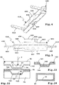
- the support assemblies 410-910 include cross members 411-911, from which side supports 412-912 protrude laterally.
- the side supports 412-912 are used for mounting on a schematically illustrated body K of a vehicle F, for example a passenger car with an internal combustion engine and / or an electric motor.
- the cross members 411-911 are often completely or partially hidden behind a rear apron or a rear bumper of the vehicle F.
- a holder 415-915 for a trailer coupling 451-951 is provided in the area of a transverse center 413 of the crossbeams 411-911.
- one or more brackets 415 'for a load carrier L can also be provided, for example.
- coupling parts M of the load carrier L can be fastened to the brackets 415 ', which have, for example, screw receptacles, plug-in receptacles or the like.
- the side members 412-912 are provided on the longitudinal ends 414 of the cross members 411-911 and are angled thereto, for example about 90 ° (larger or smaller angles are also easily possible.
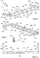
- the cross member 511 of the carrier arrangement 510 are still Side carriers 512 'are drawn in, which are suitable, for example, for mounting on a rear end plate of the body of vehicle F, on the rear longitudinal ends of the longitudinal members of the body or the like.
- the longitudinal directions of extension of side members 512' and cross member 511 are approximately parallel.
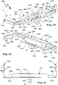
- the cross-sections 411-911 are essentially U-shaped in their basic cross-section. Side walls 421-921 and side walls 492-922 protrude at an angle from a bottom wall or base wall 420-920.
- the base wall 420-920 is approximately vertical when the carrier arrangements 410-910 are installed on the vehicle F or in the installed state, while the side walls 421-921 and 492-922 run approximately horizontally and form upper and lower walls.
- the base wall 420-920 is thus, for example, a rear wall.
- the base wall 420-920 extends in each case to the longitudinal ends 414, that is to say to the side beams 412-912. However, the base wall 920 is wider in a central region 916 of the cross member 911 and has the two upper and lower side walls 921 and 992, while sections 923 of the base wall 920 narrower towards the longitudinal ends 414 have no upper and lower legs or side walls 921-922 exhibit. Among other things, this acts in the sense of a reinforcement or higher rigidity of the cross member 911 in the central region 916.
- the side walls 421-921, 422-922 are used for reinforcement, preferably in the area of the transverse center 413. Reinforcement deformations 430-930 are also provided, which improve the rigidity of the cross members 411-911.
- notch recesses 431-433, 531-533 are provided in a preferably rounded edge area (angular or polygonal would also be possible).
- the notch depressions 431, 531 arranged next to the holder 415, 515 are deeper than the notch depressions 432, 532 arranged next to them in the direction of the longitudinal ends 414, which in turn are deeper than the notch depressions 433, 533 located near the longitudinal ends 414.
- the rigidity of the cross member 411 and 511 is thus somewhat higher in the middle than transversely on the outside or in the region of the side supports 412 and 512.
- the notch depressions 431-433, 531-533 are approximately V-shaped, whereby they are embossed, so to speak, into the material of the cross member 411, 511.
- notch recesses 431-433, 531-533 and 434-934 is only to be understood as an example.
- the V-shape is not important. U-shaped depressions, depressions elsewhere, or the like, are also readily possible.
- the cross members 811 and 911 have depressions 835, 935 in their central regions which extend deeper backwards from the base wall 820 and 920 than depressions 836 and 936 which extend between the depressions 835, 935 and the side members 812 and 912 are located.
- the very deep depressions 835 and 935 have a greater stiffening effect than the less deep depressions 836, 936.
- the depressions 835, 935 and the depressions 836, 936 preferably extend in the respective longitudinal direction of the cross members 811 and 911.
- the depressions 835, 935 and the depressions 836, 936 have base walls or base walls 837, 937 or 838 and 938, between which and the base walls 820 and 920 of the cross members 811 and 911 side walls 839, 939 are provided.
- the crossbeams 811 and 911 are cross-sectionally Z-shaped or double-Z-shaped.
- the longitudinal end regions of the depressions 835, 935, 836, 936 are expediently rounded off.
- the side beams 412-912 are integrally connected to the cross beams 411-911.
- the side supports 412-912 are essentially plate-shaped.
- the side beams 412-912 have plate-shaped walls 440.
- Bores 441 are provided for mounting the side supports 412-912 on the body K of the vehicle F, through which holes screws or fastening bolts of this type can be inserted and screwed to the body K.
- the bores 441 are located on corresponding mounting areas 446 of the side carriers 412-912. While one bore 441 is near the free end of the side member 412-912, the other bore 441 is near the cross member 411-911, approximately in the area of the notch recesses 434-934.
- the deformation structure 444 bulges or bends, for example, as shown in the drawing in the event of a rear-end collision with the vehicle F inwards toward the body K or (not shown) away from the body K.
- the deformed deformation structures 444 are shown in solid lines, the undeformed side members 412-912 are shown in dashed lines.
- the cutouts 443 are located opposite one another, which is optional, so that, as it were, a cutout is provided with the cutouts 443 lying opposite one another.
- a rear impact on the cross member 411-911 i.e. an impact on the base wall 420-920
- the body K of the vehicle F is also deformed, and in addition to the deformation structure 444 there is also a region of the body K deforming in the event of a rear impact (not shown) and thus the relative spacing of screw holes or assembly areas of the body K for connection to the bolts, not shown, penetrating the bores 441 is reduced.
- the deformation structure 444 therefore also undergoes this deformation of the body K, so that the bolts (not shown) penetrating the bores 441 remain in the corresponding assembly areas or bores of the body K and do not tear out.
- the side carriers of the carrier arrangements 410-910 could also have at least local reinforcements, for example reinforcement sections 445 or the like, which is exemplary in FIG Figure 1 is drawn.
- the reinforcing sections 445 are provided, for example, in the area of the bores 441, so that the mounting areas 446 are locally reinforced.
- the reinforcing sections 445 are, for example, bent-over sections in the manner of the side walls 421, 422 which extend away from the wall 440.
- the brackets 415-915 can be provided integrally on the crossbeams 411-911 or can also comprise attached, inserted or similarly attached components.
- plug-in receptacle elements 517, 617, 717 and 817 are provided in the carrier arrangements 510-810.
- a plug-in end 553 of a coupling arm 552 of a trailer coupling 551 (for example, a plug-in end 553 of a coupling arm 551 ( Figure 7 ) can be inserted.
- Recesses 518-818 are provided on the side walls 521-821 and 522-822, the inner contour of which corresponds to the outer contour of the plug-in receptacle elements 517-817, so that these are held in a form-fitting manner.
- the plug-in receptacle elements 517-817 are glued, welded or otherwise firmly connected to the cross members 511-811, for example.
- screw connections are also possible, in particular in order not to impair the structure or material of the crossbeams 511-811.
- the carrier arrangements 410 and 910 comprise housings 450 and 950 for a trailer coupling 451, 951.
- the trailer coupling 451, 951 comprises, for example, a coupling arm 452, 952 which is provided on a coupling module 453 or is pivotably and / or displaceably mounted directly in the housing 950, for which purpose there is a bearing arrangement, not explained in more detail, with, for example, a pivot bearing and / or a sliding bearing.
- the coupling arms 452 and 952 are mounted between a working position A which projects rearward in front of the vehicle F and is intended for pulling a trailer and a rest position R which is preferably adjusted back behind a rear apron or a bumper of the vehicle F.
- drives for adjusting the coupling arms 452 and 952 are provided between these positions, for example integrated into the Coupling module 453.
- the coupling arm 452 and / or 952 it is also possible for the coupling arm 452 and / or 952 to be pivoted manually. That does not matter.
- controls for locking the coupling arms 452 and 952 in the working position A and / or the rest position R can be provided, which is also not shown in detail.
- the coupling module 453 comprises a module housing 454 in which, for example, one or more bearings (pivot bearings and / or sliding bearings) for the coupling arm 452 and / or a lock for the coupling arm 452 is present.
- bearings pivot bearings and / or sliding bearings
- the coupling module 453 or the module housing 454 can be inserted as a whole into the housing 450 and can also be locked and / or fastened there, for example by means of screws, bolts or the like.
- the coupling module 453 has an advantageous effect in terms of stiffening the housing 450.
- the housing 450 includes, for example, a rear wall 455 and side walls 456, which extend from the rear wall 455 to the base wall 420.
- a section of the base wall 420 opposite the rear wall 455 forms a front wall of the housing 450.
- An upper section of the upper side wall 421 forms, so to speak, the upper cover of the housing 450, so that apart from a lower opening 457 through which the module housing 454 can be inserted total closed housing is formed.
- the opening 457 is provided on a section 458 of the lower side wall 422.
- a coupling arm can also be mounted directly in the housing 450, for example a receiving sleeve, a bearing arrangement, motors and the like because the housing 450 offers sufficient space.
- the module housing 454 fits positively into the interior of the housing 450, so that a lower wall or lower cover of the module housing 454 closes the opening 457, so to speak, from below.
- seals e.g. Rubber elements, and the like other, easily possible.
- the module housing 454 can also be glued into the housing 450, for example.
- the housing 950 is provided by the central recess 935.
- sealing arrangement 957 which e.g. Includes sealing lips, provided.
- the carrier arrangements 410-910 each comprise integrally produced base bodies 460-960, which are produced from a single sheet metal plate 461-961 or their bodies 468-968.
- the base bodies 460-960 each include the cross members 411-911 and integrally molded thereon the side members 412-912.
- the housings 450, 950 are also provided for the brackets 415 and 915.
- the housings 450 and 950 are therefore also integral components of the base body 460-960, which makes manufacture easier.
- the sheet metal boards 461-961 consist for example of a steel sheet, aluminum sheet or the like.
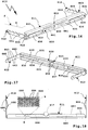
- the sheet metal plate 461 of the carrier arrangement 410 is shown as an example, which has already been cut out of a semifinished product or coil, for example by means of a laser, scissors, a punching tool or a tool arrangement which comprises one or more of the aforementioned cutting tools.
- the sheet metal plate 461 comprises, for example, a main section 462, from which the walls 440 of the side supports 412 project laterally in the longitudinal direction. Transversely to the direction of longitudinal extension, a section 463 provided to form the rear wall 455 and the side wall 456 protrude from the main section 462 and another section 464 opposite this, which later frames the opening 457, so to speak, or on which the opening 457 is formed.
- embossing lines 465 are already provided on the sheet metal plate 461, which are shown in dashed lines in the drawing and later facilitate the folding or folding or enable a targeted introduction of force. However, this is not necessary, but is an option.
- the base bodies 460-960 can already be designed in such a way by the reinforcement deformations or other measures that they have a stiffness profile or strength profile adapted to the voltage profile or an optimal introduction of force when the trailer is being pulled and / or in the event of a rear impact.
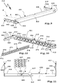
- a reinforcing body 670 is provided, which is inserted into an interior 624 of the cross member 611.
- the interior space 624 is delimited, for example, by the side walls 621 and 622 and the base wall 620.
- the reinforcing body 670 comprises, for example, a base wall 671 and side walls 672 protruding from it in a U-shape. These walls delimit an interior space in which a rib structure 673 is arranged, which has a stiffening effect.
- the rib structure 673 comprises, for example, ribs which are integrally connected to the side walls 672 and / or the base wall 671 and support them, so to speak.
- the rib structure 673 also acts in the sense of reinforcing the cross member 611, on which the reinforcing body 670 bears in a form-fitting manner or is arranged in a form-fitting manner in the interior.
- rib structures that are optimally adapted to a strength curve or stress curve can also be provided here, i.e. that, for example, a greater stiffening is desired in the area of the transverse center 613, while weaker ribs 675 and / or fewer ribs are provided along the outside or transversely outside, that is to say in the area of the longitudinal ends 414, and strong ribs 674 in the central area 413 Rib structure 673, for example, run diagonally between the side walls 672, in particular at an angle of approximately 45 ° thereto, and intersect, so that an X-shaped rib structure (in a plan view from behind) is provided.
- reinforcing body 670 there is at least one reinforcing body 670 between the holder 615 and the side supports 12 intended.
- the reinforcing body 670 is glued into the interior 624, for example.
- a rib structure or the like other reinforcing component can also be attached to a component manufactured according to the invention, i.e. e.g. can be molded from a sheet metal base body.
- a rib structure consists of plastic, which is also expediently the case with the reinforcing body 670.
- a concept that is particularly important in the one-piece, i.e. support arrangements 410-910 consisting of a base body 460-960 is advantageous, but also, for example in the case of multi-part support arrangements, not shown in the drawing, provides in particular local reinforcement of the support arrangement, where the rigidity and / or strength of the support arrangement should expediently be higher. Therefore, the concept described below is not applicable to the use of the advantageous basic bodies, which are made in one piece from a sheet metal plate, but can also be used with advantage in any other support arrangement, for example made of profile elements or the like.
- fiber material elements 480 for example triangular fiber material elements, are provided on the upper side wall 421 of the carrier arrangement 410 or of the cross member 411.
- This concept is also provided for the carrier arrangement 510, that is to say that triangular fiber material elements 580 are also provided on the cross member 511, so that an area between the center 513 and the side beams 512 is reinforced. It is also advantageous to provide reinforcement in the area of the holder 515.
- a fiber material element 581 is therefore provided there, which reinforces the holder 515 or the area around the recess 518, so to speak.
- the plug-in receptacle element 517 is therefore held particularly well by the upper side wall 521 and / or the lower side wall 522, which is optionally reinforced there with the aid of the fiber material element 581.
- a fiber material element 581 can be provided, for example, in one or both side walls 521 and / or 522.
- fiber material elements 680 are provided on the side next to the holder 615, which reinforce the upper side wall 621.
- the fiber material elements 680 comprise a mesh structure 683, a section A of which is shown enlarged.
- the meshing of fibers 684 ensures optimal reinforcement and tensile strength.
- a fiber material element 780 is glued into the interior 724 of the cross member 711.
- the fiber material element 780 is glued flatly on the inner sides of the base wall 720 and the upper and lower side walls 721 and 722, for example by means of a thermoplastic adhesive, which will become clear later.
- fiber material elements 880 are provided on the upper side wall 821.
- the fiber material elements 880 comprise, for example, a fiber mesh 885, which can be seen in an enlarged section B, with fibers 884, 886 which cross each other.
- fiber material elements can also be provided elsewhere, for example in the area of the recess 835, for example on the side wall 839 next to the holder 815.
- fiber material elements 881 are provided, which for example have a mesh structure such as the mesh structure 683 and / or a fiber mesh such as comprise the fiber braid 885.
- a fibrous material element 980 is also shown in the carrier arrangement 910, for example on the upper side wall 921 in the region of the holder 915. It would also be possible, for example, to provide one or more fibrous material elements around the cutout or the opening 957, which thus act locally reinforcing, where the opening 957 represents a certain weakening of the base body 960.
- Fiber arrangements 587-987 of the fiber material elements 580-980 or 581, 881, 981 include, for example, plastic fibers, in particular aramid fibers, and / or carbon fibers and / or Glass fibers or the like other non-organic materials that are tensile.
- plastic fibers in particular aramid fibers, and / or carbon fibers and / or Glass fibers or the like other non-organic materials that are tensile.
- other fibers are also possible, for example natural fibers made of sisal, coconut and the like.
- the fiber assemblies 587-987 can e.g. Include non-woven fiber material elements, in particular nonwovens and / or felts and / or thread or fiber fabrics, but also include a woven fabric and / or a fiber braid.
- the fiber assemblies 587-987 have e.g. fibers meshed with one another, in particular to form a knitted fabric and / or a knitted fabric.
- the fiber material elements 580-980 or 581, 881, 981 reinforce the base body 460-960, thus supporting components 488-988.
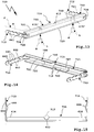
- the fiber material elements can be glued to the base body 460-960, for example by means of normal gluing, press gluing or the like. It is preferred to produce a type of composite sheet by means of a pressing tool, which is described in Figure 22 is shown schematically.
- a pressing tool 90 has a lower pressing element 91 and an upper pressing element 92.
- a receptacle 93 is provided on the lower pressing element 91, and a projection 94 corresponding to the recess or receptacle 93 is provided on the upper pressing element 92.
- the fiber material element 780 is to be glued there.
- the section 766 extends into the receptacle 93, while the fiber material element 780 still has a flat structure.
- the fiber material element 780 could already have a shape adapted to the receptacle 93, which it will later use according to the view Figure 23 Has. If the top Tool element or pressing element 92 is moved towards the lower pressing element 91 (represented by an arrow P), this presses the fiber material element 780 into the trough at the section 766, so that the fiber material element 780 assumes the contour of the trough or receptacle 93.
- the upper and / or lower pressing element 91/92 are heated (for example with a heater 99) so that an adhesive, for example a resin, a thermoplastic or the like, located in the fibers of the fiber material element 780 becomes adhesive and to the section 766 of the base body 760 adheres.
- an adhesive for example a resin, a thermoplastic or the like
- a further layer for example a sheet metal layer 767, can be pressed or stamped onto this layer structure comprising the base body 760 and the fiber material element 780, so that a kind of sandwich is produced.
- the fiber material element can also be configured in the manner of a sleeve, which is shown in Figure 24 becomes clear.
- a profile body 96 for example a tubular body, for example made of sheet metal material, is provided, which is surrounded by a fiber material element sleeve 97 and thus reinforced.
Description
Die Erfindung betrifft eine Trägeranordnung für eine Anhängekupplung oder einen Lastenträger, gemäß dem Oberbegriff des Anspruchs 1.The invention relates to a carrier arrangement for a trailer coupling or a load carrier, according to the preamble of claim 1.
Eine derartige Trägeranordnung ist in
Solche Trägeranordnungen werden in der Regel verborgen unter einem Heck-Stoßfänger des Fahrzeugs, beispielsweise eines Personenkraftwagens, insbesondere mit einem Verbrennungsmotor, angebracht und tragen die Anhängekupplung oder eine Halterung dafür und/oder gegebenenfalls auch Halterungen für einen Lastenträger, die an der Trägeranordnung angeordnet werden können.Such carrier arrangements are generally hidden under a rear bumper of the vehicle, for example a passenger car, in particular with an internal combustion engine, and carry the trailer coupling or a holder therefor and / or possibly also holders for a load carrier, which can be arranged on the carrier arrangement .
Aus
Beispielsweise ist in
Ferner ist es zweckmäßig, wenn die Trägeranordnung konstruktiv einfach ist, das heißt leicht zu fertigen.Furthermore, it is expedient if the carrier arrangement is structurally simple, that is to say easy to manufacture.
Die Trägeranordnung ist vorzugsweise möglichst leicht.The carrier arrangement is preferably as light as possible.
Es ist daher die Aufgabe der vorliegenden Erfindung, eine verbesserte Trägeranordnung bereitzustellen.It is therefore the object of the present invention to provide an improved carrier arrangement.
Zur Lösung der Aufgabe ist eine Trägeranordnung gemäß der technischen Lehre des Anspruchs 1 vorgesehen.To achieve the object, a carrier arrangement is provided in accordance with the technical teaching of claim 1.
Es ist dabei ein Grundgedanke, dass die Trägeranordnung einen Grundkörper mit Querträger und einen Seitenträger und/oder Gehäuse für die Halterung der Anhängekupplung umfasst, wobei der Grundkörper aus einer einzigen Blechplatine gefertigt ist, also aus einem Stanz-Biegeteil oder Bauteil, das zunächst ausgeschnitten wird und anschließend z.B. umgekantet, umgebördelt oder dergleichen anderweitig umgeformt wird. Der Grundkörper ist einfach zu fertigen. Es genügen wenige Arbeitsgänge. Die Vorgänge, Schweißen, Kleben, Nieten etc. sind nicht oder jedenfalls in einem deutlich geringeren Umfang notwendig. Dies bedeutet allerdings nicht, dass es nicht auch vorteilhaft sein kann, Abschnitte der erfindungsgemäßen Trägeranordnung zu schweißen und/oder zu kleben und/oder zu nieten.It is a basic idea that the carrier arrangement comprises a base body with cross member and a side member and / or housing for holding the trailer coupling, the base body being made from a single sheet metal plate, i.e. from a stamped and bent part or component that is first cut out and then, for example, folded, flanged or the like is otherwise formed. The basic body is easy to manufacture. Few operations are sufficient. The processes, welding, gluing, riveting etc. are not necessary or at least to a significantly lesser extent. However, this does not mean that it cannot also be advantageous to weld and / or glue and / or rivet sections of the carrier arrangement according to the invention.
Weiterhin werden verhältnismäßig wenige Teile benötigt. Beispielsweise müssen nicht verschiedene Querrohre oder unterschiedliche Profilformen am Lager vorgehalten werden, um einen jeweils für einen Fahrzeugtyp angepassten Träger der Anhängekupplung oder des Lastenträgers herzustellen.Furthermore, relatively few parts are required. For example, different cross tubes or different profile shapes do not have to be kept in stock in order to produce a carrier of the trailer coupling or of the load carrier which is respectively adapted for a vehicle type.
Das Gefüge der Trägeranordnung bzw. des Grundkörpers ist stabil, weil keine Schweißnähte notwendig sind oder jedenfalls nur wenige Schweißnähte, so dass die Gefahr, dass die Schweißnaht selbst oder eine sich neben der Schweißnaht befindliche Region des Grundkörpers bricht, verringert oder gar vollständig vermieden ist. Das Gefüge ist also weit gehend homogen, was eine höhere Belastbarkeit der Trägeranordnung bei gleichzeitig geringem Gewicht und Bauvolumen möglich macht.The structure of the carrier arrangement or of the base body is stable because no weld seams are necessary or at least only a few weld seams, so that the risk of the weld seam itself or a region of the base body located next to the weld seam is reduced or even completely avoided. The structure is therefore largely homogeneous, which makes a higher load-bearing capacity of the support arrangement possible, while at the same time being light in weight and construction volume.
Das Gehäuse für die Halterung der Anhängekupplung kann die Anhängekupplung, beispielsweise deren Antriebsmodul, Lager oder dergleichen, vollständig einhausen. Es versteht sich, dass das Gehäuse auch nur ein Teil-Gehäuse sein kann, d.h. dass zusätzliche Abdichtmaßnahmen zur Abdichtung des Gehäuses gegenüber Umwelteinflüssen möglich sind.The housing for holding the trailer coupling can completely enclose the trailer coupling, for example its drive module, bearings or the like. It is understood that the housing can also be only a partial housing, i.e. that additional sealing measures to seal the housing against environmental influences are possible.
Eine bevorzugte Ausführungsform sieht vor, dass die Halterung der Anhängekupplung und/oder des Lastenträgers im Sinne einer Versteifung wirkt, beispielsweise als eine Art Kasten ausgestaltet ist, der die Trägeranordnung, insbesondere im Bereich des Gehäuses für die Halterung, versteift.A preferred embodiment provides that the holder of the trailer coupling and / or the load carrier acts in the sense of stiffening, for example is designed as a type of box that stiffens the carrier arrangement, in particular in the area of the housing for the holder.
Das Gehäuse für die Halterung der Trägeranordnung kann sehr einfach verschlossen werden, beispielsweise durch ein Antriebsmodul oder Lagermodul der Anhängekupplung selbst. Aber auch eine zusätzliche Abdeckung, zum Beispiel eine Folie, eine Platte oder dergleichen, ist ohne weiteres möglich.The housing for holding the carrier arrangement can be closed very easily, for example by a drive module or bearing module of the trailer coupling itself. However, an additional cover, for example a film, a plate or the like, is also easily possible.
Die Blechplatine ist beispielsweise aus Metallblech, z.B. Stahlblech, Aluminiumblech oder dergleichen, und/oder aus einem Polymerblech. Es sind zum Beispiel so genannte Organobleche möglich. Weiterhin kann das Grundmaterial für die Blechplatine ein Kaltwalzprodukt oder ein Warmwalzprodukt sein.The sheet metal plate is for example made of sheet metal, e.g. Steel sheet, aluminum sheet or the like, and / or from a polymer sheet. So-called organic sheets are possible, for example. Furthermore, the base material for the sheet metal blank can be a cold rolled product or a hot rolled product.
Bevorzugt ist es, wenn die Blechplatine mittels eines thermischen Trennverfahrens, zum Beispiel Laserschneiden, hergestellt wird. Es ist aber auch möglich, zum Beispiel die Platine mit einer Schere aus dem Halbzeug auszuscheiden oder mit einem Stanzwerkzeug auszustanzen, bevor sie zu dem Grundkörper umgeformt wird.It is preferred if the sheet metal blank is produced by means of a thermal separation process, for example laser cutting. However, it is also possible, for example, to cut out the blank from the semi-finished product with scissors or to punch it out with a punching tool before it is formed into the base body.
Es können lokale Versteifungselemente eingebracht werden, wo es notwendig ist. Beispielsweise sind die Versteifungselemente entsprechend der späteren Belastung, zum Beispiel durch einen Anhänger, an dem Grundkörper vorgesehen. Die zugeschnittene Blechplatine oder der Zuschnitt der Blechplatine ist zweckmäßigerweise an das Fließverhalten angepasst. Auch eine Gewichtsoptimierung ist möglich. Beispielsweise können einzelne Aussparungen oder dergleichen vorgesehen sein, um das Gewicht des Grundkörpers zu reduzieren. Eine Aussparung oder Öffnung kann auch eine verstärkende Funktion haben, indem beispielsweise Randbereiche der Aussparung umgekantet sind.Local stiffening elements can be introduced where necessary. For example, the stiffening elements are provided on the base body in accordance with the later load, for example by a trailer. The cut sheet metal plate or the cutting of the sheet metal plate is expediently adapted to the flow behavior. Weight optimization is also possible. For example, individual cutouts or the like can be provided in order to reduce the weight of the base body. A recess or opening can also have a reinforcing function, for example in that edge regions of the recess are folded over.
Das erfindungsgemäße Verfahren funktioniert beispielsweise folgendermaßen:
Die Blechplatine wird aus einem Grundmaterial oder Halbzeug ausgeschnitten, beispielsweise mittels eines Lasers, einer Schere, eines Stanzwerkzeugs oder dergleichen.The method according to the invention works, for example, as follows:
The sheet metal blank is cut out of a base material or semi-finished product, for example by means of a laser, scissors, a punching tool or the like.
Die Blechplatine wird anschließend zu einem Blechprägeteil, nämlich dem Grundkörper umgeformt, wobei integral beispielsweise die Seitenträger, ein Gehäuse oder eine Halterung für die Anhängekupplung oder dergleichen in einem Schritt angeformt bzw. umgeformt werden.The sheet metal blank is then formed into a stamped sheet metal part, namely the base body, integrally for example the side carriers, a housing or a holder for the trailer coupling or the like are molded or reshaped in one step.
Sofern es erforderlich ist, können beispielsweise die Seitenträger und/oder der Querträger - selbstverständlich auch jedes andere Element des Grundkörpers - nachkalibriert werden, um eine optimale Maßhaltigkeit bzw. Maßgenauigkeit für die Anbringung an dem Zugfahrzeug bzw. dem Fahrzeug zu ermöglichen.If necessary, the side beams and / or the cross beams - of course also any other element of the base body - can be recalibrated in order to enable optimum dimensional accuracy or dimensional accuracy for attachment to the towing vehicle or the vehicle.
Wenn größere Stückzahlen gewünscht sind, ist es möglich, beispielsweise ein Blech-Wickel, ein sogenanntes Coil, seitlich zu beschneiden und anschließend im Umformwerkzeug weiter zu bearbeiten. Dort wird das Blechprägeteil, nämlich der Grundkörper, hergestellt. Das fertige Blechteil wird aus dem Umformwerkzeug entfernt und direkt am Fahrzeug montiert, gegebenenfalls vorher noch nachkalibriert.If larger quantities are desired, it is possible, for example, to cut a sheet metal coil, a so-called coil, on the side and then to further process it in the forming tool. The stamped sheet metal part, namely the base body, is produced there. The finished sheet metal part is removed from the forming tool and mounted directly on the vehicle, if necessary recalibrated beforehand.
Selbstverständlich können im Zusammenhang mit der Montage oder vor der Montage am Fahrzeug auch Bauteile an der Trägeranordnung angeordnet werden, zum Beispiel Montageelemente, Befestigungsösen, Schrauben oder dergleichen.Of course, components can also be arranged on the carrier arrangement in connection with assembly or before assembly on the vehicle, for example assembly elements, fastening eyes, screws or the like.
Durch gezielt eingebrachte Abkantungen, Falze, Ausformungen von Rippen, Sicken oder dergleichen, können Grundkörper mit sehr hoher Steifigkeit hergestellt werden. Selbstverständlich ist diese Steifigkeit nicht am gesamten Grundkörper erforderlich, sondern kann auch lokal vorgesehen sein. Beispielsweise ist der Querträger im Bereich der Halterung für die Anhängekupplung oder den Lastenträger besonders steif und belastbar. Dies kann beispielsweise dadurch erzielt werden, dass eine Verstärkungsumformung im Bereich der Halterung besonders tief eingeprägt oder umgeformt ist.Base bodies with a very high degree of rigidity can be produced by means of deliberately introduced bevels, folds, ribs, beads or the like. Of course, this rigidity is not required on the entire base body, but can also be provided locally. For example, the cross member in the area of the holder for the trailer coupling or the load carrier is particularly stiff and resilient. This can be achieved, for example, in that a reinforcement deformation is particularly deeply embossed or formed in the area of the holder.
Selbstverständlich kann an dem Grundkörper auch eine weitere Komponente, zum Beispiel eine komplementäre, ebenfalls belastbare Schale angeformt werden. Dadurch entsteht eine hochfeste, dünnwandige und leichte Konstruktion.Of course, a further component, for example a complementary, likewise resilient shell, can also be molded onto the base body. This creates a high-strength, thin-walled and lightweight construction.
Weiterhin ist es möglich, den Grundkörper je nach Bedarf partiell zu versteifen, beispielsweise durch entsprechende Einleger oder dergleichen.Furthermore, it is possible to partially stiffen the base body as required, for example by means of appropriate inserts or the like.
Bevorzugt hat der Querträger beispielsweise einen U-förmigen oder Z-förmigen oder V-förmigen oder W-förmigen Querschnitt. Selbstverständlich sind auch andere Querschnitte ohne weiteres möglich.The cross member preferably has, for example, a U-shaped or Z-shaped or V-shaped or W-shaped cross section. Of course, other cross sections are also easily possible.
Der Grundkörper kann beispielsweise aus Stahl und/oder Leichtmetall bestehen. Der Grundkörper selbst kann an sich schon dünnwandig, leicht und hochfest sein. Der mindestens eine an dem Grundkörper angeordnete Verstärkungskörper erhöht die Steifigkeit des Tragbauteils. So kann beispielsweise eine dünnwandige Metallkonstruktion des Grundkörpers durch eine Versteifung aus Kunststoff so verstärkt werden, dass sie die durch die Anhängekupplung oder den Lastenträger verursachten Kräfte, Aufprallkräfte bei einem Unfall oder dergleichen ohne weiteres aufnehmen kann.The base body can consist of steel and / or light metal, for example. The basic body itself can be thin-walled, light and high-strength. The at least one reinforcing body arranged on the base body increases the rigidity of the supporting component. For example, a thin-walled metal structure of the base body can be reinforced by a stiffener made of plastic so that it can easily absorb the forces caused by the trailer coupling or the load carrier, impact forces in the event of an accident or the like.
Der Grundkörper kann zur Gewichtsreduzierung Aussparungen aufweisen. Schon beim Zuschnitt von Platinen zur Herstellung des Grundkörpers oder durch Nachbearbeitung des Grundkörpers können vorteilhaft weitere Potenziale zur Massereduzierung durch lokale Ausnehmungen genutzt werden. Z.B. durch eine entsprechende Werkzeugkontur können auch lokale Ausformungen am insbesondere als Schale ausgebildeten Grundkörper erzeugt werden, die zur strukturellen Steifigkeitserhöhung beitragen.The base body can have cutouts to reduce weight. Even when cutting blanks for the production of the base body or by reworking the base body, further potentials for reducing the mass can be used advantageously by local recesses. For example, a corresponding tool contour can also be used to produce local formations on the base body, which is designed in particular as a shell, which contribute to increasing the structural rigidity.
Zweckmäßigerweise ist bei einer Aussparung mindestens ein umgekanteter Abschnitt und/oder eine lokale Auskragung vorgesehen. Jedenfalls ist es vorteilhaft, wenn eine Aussparung nicht nur Gewicht reduzierend wirkt, sondern gleichzeitig auch noch verstärkend oder versteifend.At least one folded section and / or a local projection is expediently provided in a recess. In any case, it is advantageous if a recess not only has a weight-reducing effect, but at the same time is also reinforcing or stiffening.
Der Grundkörper und/oder die Blechplatine sind vorzugsweise mittels eines thermischen Trennverfahrens, zum Beispiel Lasertrennen, hergestellt. Aber auch ein Schneiden aus einem Coil-Halbzeug, zum Beispiel mittels einer Scheranordnung (so genanntes Scherschneiden) ist möglich. Die Platine kann durch Stanzen hergestellt sein. Es versteht sich, dass die vorgenannten Trennverfahren sowohl bei der Blechplatine, d.h. noch vor der Herstellung des Grundkörpers, durch Umformen, als auch später beim fertiggestellten Grundkörper möglich sind, der sozusagen durch mindestens einen Zuschnitt noch nachgearbeitet wird. Das muss aber nicht sein.The base body and / or the sheet metal plate are preferably produced by means of a thermal separation process, for example laser cutting. But cutting from a semi-finished coil is also possible, for example using a shear arrangement (so-called shear cutting). The board can be made by stamping. It goes without saying that the aforementioned separation processes apply to both the sheet metal plate, i.e. even before the production of the base body, by forming, as well as later on the finished base body, which can be reworked by at least one cut, so to speak. This need not be.
Der Grundkörper ist beispielsweise durch eine Kaltumformung oder eine Warmumformung oder beides gebildet. Es kann z.B. eine Warmumformung mit kontrolliertem Abschrecken im Werkzeug, also ein Presshärten, vorgesehen sein.The base body is formed, for example, by cold forming or hot forming or both. For example, hot forming with controlled quenching in the tool, that is press hardening, may be provided.
Bevorzugt ist es, wenn der Grundträger, also beispielsweise der Querträger und die integral daran angeordneten Seitenträger, keine Schweißnaht aufweist. Das kann man durch Kaltumformung, Warmumformung oder beides herstellen.It is preferred if the base support, that is to say for example the cross member and the side supports integrally arranged thereon, has no weld seam. This can be done by cold forming, hot forming or both.
Zwar ist es bevorzugt, dass keine Schweißnaht vorhanden ist. Selbstverständlich ist es aber auch möglich, insbesondere im Bereich des Gehäuses für die Halterung der Anhängekupplung oder des Lastenträgers, mindestens eine Schweißnaht oder sonstige thermische Verbindungen vorzusehen.It is preferred that there is no weld seam. Of course, it is also possible, in particular in the area of the housing for holding the trailer coupling or the load carrier, to provide at least one weld seam or other thermal connections.
Bevorzugt ist es beispielsweise, wenn sich zwei benachbarte Abschnitte des Grundkörpers überlappen, stumpf aneinander stoßen oder dergleichen. Die benachbarten Abschnitte können auch mittels eines Falzes, also auch eine Umformer-Behandlung, miteinander verbunden werden. Damit das Gefüge möglichst nicht beeinträchtigt wird, sind Klebeverbindungen zwischen benachbarten Abschnitten des Grundkörpers, beispielsweise Seitenwänden des Gehäuses für die Halterung, Übergangsbereiche zwischen Seitenträger und Querträger oder dergleichen, möglich.It is preferred, for example, if two adjacent sections of the base body overlap, butt against one another or the like. The adjacent sections can also be connected to one another by means of a fold, that is to say also a converter treatment. So that the structure is not impaired as far as possible, adhesive connections between adjacent sections of the base body, for example side walls of the housing for the holder, transition regions between the side member and cross member or the like, are possible.
Wenn eine Schweißnaht oder eine Verschweißung erforderlich ist, ist eine Widerstandsverschweißung, zum Beispiel eine Rollnahtverschweißung und/oder eine Punkt-Verschweißung oder dergleichen, vorteilhaft, um das Gefüge des Grundkörpers möglichst wenig zu beeinträchtigen.If a weld seam or a weld is required, a resistance weld, for example a roll seam weld and / or a spot weld or the like, is advantageous in order to impair the structure of the base body as little as possible.
Der Grundkörper hat erfindungsgemäß mindestens eine Verstärkungsumformung, nämlich eine Verstärkungssicke, und/oder zweckmäßigerweise eine Ausnehmung zur Gewichtsreduktion. Eine Ausnehmung, die eine Gewichtsreduktion zur Folge hat, kann beispielsweise umgekantete Wandabschnitte haben.According to the invention, the base body has at least one reinforcement deformation, namely a reinforcement bead, and / or expediently a recess for weight reduction. A recess that results in a reduction in weight can have, for example, folded-over wall sections.
Eine im Bereich einer Quermitte des Querträgers zwischen den Seitenträgern angeordnete Verstärkungsumformung hat zweckmäßigerweise eine größere, sich von einer Seitenfläche des Querträgers weg erstreckende Tiefe als eine sich zwischen der Quermitte und einen Seitenträger vorgesehene (zweite) Verstärkungsumformung. Die tiefere Verstärkungsumformung versteift den Querträger beispielsweise besser als die weniger tiefe Verstärkungsumformung, was insbesondere im Bereich der Quermitte des Querträgers (zwischen den Seitenträgern) einen Vorteil darstellt.A reinforcement deformation arranged in the area of a transverse center of the cross member between the side supports expediently has a greater depth, which extends away from a side surface of the cross member, than a (second) reinforcement deformation provided between the transverse center and a side support. The deeper reinforcement deformation stiffens the crossbeam, for example, better than the less deep reinforcement deformation, which is an advantage particularly in the area of the transverse center of the crossbeam (between the side girders).
Eine Verstärkungsumformung, vorzugsweise eine Kerbvertiefung, kann beispielsweise an einem Kantenbereich des Grundträgers vorgesehen sein. Insbesondere ist eine solche Kantenvertiefung oder sind mehrere solche Kantenvertiefungen beim Querträger, der besonders steif sein soll, vorteilhaft.A reinforcement deformation, preferably a notch depression, can be provided, for example, on an edge region of the base support. Such an edge recess or several such edge recesses is particularly advantageous in the case of the cross member, which is said to be particularly rigid.
Die Seitenträger können mit dem Querträger fluchtend sein. Die Seitenträger können auch parallel zum Querträger verlaufen oder etwa parallel, d.h. mit einem sehr stumpfen Winkel von beispielsweise 185° bis 175° zum Querträger stehen und diesen sozusagen in Längserstreckungsrichtung verlängern. Beispielsweise sind die Seitenträger als Montagebleche zur Montage am Heck-Bereich der Karosserie des Fahrzeugs vorgesehen, zum Beispiel am hinteren Heck-Abschlussblech. Es sind Seitenträger, die in der Art von Schwertern ausgestaltet sind, d.h. Seitenträger, die winkelig zum Querträger stehen, beispielsweise in einem Winkel von etwa 80-110°, normalerweise etwa 90°, möglich.The side beams can be aligned with the cross beam. The side members can also run parallel to the cross member or approximately parallel, i.e. stand at a very obtuse angle of, for example, 185 ° to 175 ° to the cross member and extend it, so to speak, in the longitudinal direction. For example, the side supports are provided as mounting plates for mounting on the rear area of the body of the vehicle, for example on the rear rear end plate. They are side supports that are designed in the manner of swords, i.e. Side beams that are angled to the cross beam, for example at an angle of about 80-110 °, usually about 90 °, possible.
Mindestens ein Seitenträger weist zweckmäßigerweise eine Deformationsstruktur zur geplanten Deformation bei einem Heckaufprall auf das Fahrzeug auf. Dieser Ansatz, der an sich eine eigenständige Erfindung darstellt, stellt sicher, dass der Seitenträger nachgibt und die Montagebereiche des Seitenträgers ihre Position relativ zu den Montagebereichen der Karosserie des Fahrzeugs beibehalten. Diese Erfindung betrifft also z.B. eine Trägeranordnung für eine Anhängekupplung oder einen Lastenträger, umfassend einen Querträger und mit dem Querträger verbundene Seitenträger zur Montage an einem Heck einer Karosserie eines Fahrzeugs, sowie mindestens eine an dem Querträger angeordnete Halterung für eine Anhängekupplung oder für ein Kupplungsteil eines Lastenträgers, wobei vorgesehen ist, dass mindestens ein Seitenträger eine Deformationsstruktur zur geplanten Deformation bei einem Heckaufprall auf das Fahrzeug aufweist. Beispielsweise reißen deshalb Schrauben, mit denen der Seitenträger am Fahrzeug befestigt ist, nicht aus. Es versteht sich, dass eine derartige Ausgestaltung der Seitenträger eine an sich eigenständige Erfindung darstellt.At least one side carrier expediently has a deformation structure for the planned deformation in the event of a rear-end collision with the vehicle. This approach, which is a stand-alone invention in itself, ensures that the side member yields and the mounting areas of the side member maintain their position relative to the mounting areas of the body of the vehicle. This invention therefore relates, for example, to a carrier arrangement for a trailer coupling or a load carrier, comprising a cross member and side carriers connected to the cross member for mounting on a rear of a body of a vehicle, and at least one holder arranged on the cross member for a trailer coupling or for a coupling part of a load carrier , it being provided that at least one side carrier has a deformation structure for the planned deformation in the event of a rear-end collision with the vehicle. For example, therefore, screws with which the Side carrier is attached to the vehicle, not from. It goes without saying that such a configuration of the side carriers represents an invention which is in itself independent.
Es kann vorgesehen sein, muss aber nicht, dass die Trägeranordnung einen aus einer Blechplatine durch Umformen gefertigten, den Querträger umfassenden Grundkörper umfasst. Mithin müssen also die Seitenträger nicht integral an den Querträger angeformt sein, sondern können beispielsweise auch mit einem Profilrohr verbunden sein, das sich in Querrichtung hinter dem Fahrzeug erstreckt (wenn es dort montiert ist) mithin also den Querträger darstellt. Der Querträger, an dem ein derartig deformierbarer Seitenträger angeordnet ist, kann auch ein durch Umformung hergestellter Träger, also ein Umform-Querträger, zum Beispiel ein Guss-Querträger, sein.It can be provided, but does not have to, that the carrier arrangement comprises a base body which is produced from a sheet metal blank by reshaping and comprises the cross member. Thus, the side members do not have to be integrally formed on the cross member, but can also be connected, for example, to a profile tube that extends transversely behind the vehicle (if it is mounted there) and thus represents the cross member. The cross member, on which such a deformable side member is arranged, can also be a support produced by shaping, that is to say a shaping cross member, for example a cast cross member.
Bevorzugt befindet sich die Deformationsstruktur zwischen zwei Montagebereichen des Seitenträgers, die zur Montage an der Karosserie des Fahrzeugs vorgesehen sind. Der Seitenträger macht also eine Deformation der Karosserie bzw. eines Abschnitts der Karosserie, der sich neben der Deformationsstruktur des Seitenträgers erstreckt, korrespondierend mit. Verformt sich also die Karosserie, verformt sich der Seitenträger ebenfalls mit bzw. umgekehrt. Die Montagebereiche des Seitenträgers und die entsprechenden Montagepunkte an der Karosserie behalten ihre Relativposition weitgehend, so dass Schrauben oder andere Befestigungsmittel (Verschweißung, Verkleben oder dergleichen) nicht beschädigt werden.The deformation structure is preferably located between two mounting areas of the side carrier, which are provided for mounting on the body of the vehicle. The side carrier thus also undergoes a deformation of the body or a section of the body that extends alongside the deformation structure of the side carrier. If the body deforms, the side carrier also deforms with or vice versa. The mounting areas of the side member and the corresponding mounting points on the body largely retain their relative position so that screws or other fastening means (welding, gluing or the like) are not damaged.
Eine bevorzugte Variante der Trägeranordnung sieht vor, dass mindestens ein Tragbauteil der Trägeranordnung, insbesondere der Querträger, durch mindestens ein eine Faseranordnung aufweisendes Faserwerkstoffelement verstärkt ist.A preferred variant of the carrier arrangement provides that at least one support component of the carrier arrangement, in particular the cross member, is reinforced by at least one fiber material element having a fiber arrangement.
Es ist ein Grundgedanke der Erfindung, ein Tragbauteil der Trägeranordnung, zum Beispiel den Querträger, Seitenträger, die Halterung für die Anhängekupplung oder das Kupplungsteil, durch ein Faserwerkstoffelement mit einer Faseranordnung zu verstärken. Das Grundmaterial, beispielsweise ein entsprechendes Blech, der so verstärkten Komponente, kann verhältnismäßig dünn ausgestaltet sein. Somit können beispielsweise Verbundbleche hergestellt werden, die relativ dünnes Blech enthalten und anschließend durch den Faserverbundwerkstoff bzw. das Faserwerkstoffelement verstärkt sind.It is a basic concept of the invention to reinforce a support component of the support arrangement, for example the cross member, side support, the holder for the trailer coupling or the coupling part, by means of a fiber material element with a fiber arrangement. The base material, for example a corresponding sheet of the component reinforced in this way, can be made relatively thin. Thus, for example, composite sheets can be produced that contain relatively thin sheet metal and are then reinforced by the fiber composite material or the fiber material element.
Die Fasern können beispielsweise in einer Richtung liegen. Es sind aber auch mehrere Lagen von Fasern möglich, wobei sich die Faser-Längserstreckungsrichtungen kreuzen können, zueinander winkelig sind oder dergleichen. Das Faserwerkstoffelement kann beispielsweise ein Non-Woven-Faserwerkstoffelement sein, zum Beispiel ein Vlies, ein Filz oder dergleichen. Das Faserwerkstoffelement kann aber auch ein Gewebe oder ein Fasergeflecht umfassen. Selbstverständlich können die Fasern auch miteinander vermascht sein, zum Beispiel zu einem so genannten Gewirk oder Gestrick. Alle vorgenannten Arten und Formen der Faser-Anordnung können selbstverständlich zu einem einzigen, sozusagen in sich hybriden Faserwerkstoffelement zusammengefasst sein.The fibers can be in one direction, for example. However, several layers of fibers are also possible, the longitudinal directions of the fibers being able to cross, being angled to one another or the like. The fiber material element can, for example, be a non-woven fiber material element, for example a nonwoven, a felt or the like. However, the fiber material element can also comprise a woven fabric or a fiber braid. Of course, the fibers can also be meshed with one another, for example to form a so-called knitted fabric. All of the aforementioned types and forms of fiber arrangement can of course be combined into a single, so to speak hybrid fiber material element.
Das Faserwerkstoffelement kann eine duroplastische und/oder thermoplastische Werkstoffbasis oder Matrix haben. Die Matrix nimmt die Fasern auf und stützt diese und leitet Kräfte auf sie ein. Die Matrix erfüllt auch die Klebefunktion, z.B. durch Erhitzen. Die Matrix kann auch ohne ein Erhitzen klebefähig sein. Vorzugsweise wird die Matrix ausgehärtet.The fiber material element can have a thermosetting and / or thermoplastic material base or matrix. The matrix picks up and supports the fibers and applies forces to them. The matrix also fulfills the adhesive function, e.g. by heating. The matrix can also be adhesive without heating. The matrix is preferably cured.
Die duroplastische Variante eignet sich dazu, dass beispielsweise das Faserwerkstoffelement, hier vorzugsweise in Form eines sogenannten Prepregs oder Formkörpers, als Ganzes erhitzt wird oder im Zusammenhang mit der Umformung des durch das Faserwerkstoffelement verstärkten Tragbauteil erhitzt wird, wodurch diese Faser-Matrix-Kombination klebfähig ist und an dem Tragbauteil bzw. dessen Grundkörper anhaftet.The thermosetting variant is suitable for heating, for example, the fiber material element, here preferably in the form of a so-called prepreg or molded body, as a whole is heated or in connection with the deformation of the support component reinforced by the fiber material element, whereby this fiber-matrix combination is adhesive and adheres to the support component or its base body.
Die duroplastische Matrix eignet sich dazu, dass beispielsweise das Faserwerkstoffelement als Ganzes erhitzt wird oder im Zusammenhang mit der Umformung des durch das Faserwerkstoffelement verstärkten Tragbauteils erhitzt wird, wodurch das Faserwerkstoffelement klebfähig wird und an dem Tragbauteil bzw. dessen Grundkörper anhaftet.The thermosetting matrix is suitable, for example, for heating the fiber material element as a whole or heating it in connection with the deformation of the support component reinforced by the fiber material element, as a result of which the fiber material element becomes adhesive and adheres to the support component or its base body.
Bei der thermoplastischen Variante ist das Faserwerkstoffelement zweckmäßigerweise mit einem Klebstoff an das Tragbauteil angeklebt. Beispielsweise wird dafür ein Mehrkomponenten-Klebstoff verwendet, der sich für Kunststoff-Metall-Verbindungen und/oder Kunststoff-Kunststoff-Verbindungen eignet. Bevorzugt sind Klebstoffe, die beim späteren Recycling Vorteile haben. Der Klebstoff kann beispielsweise bei einer Wärmebehandlung flüssig bzw. klebend werden und die Klebeverbindung zwischen dem mindestens einen Faserwerkstoffelement und dem solchermaßen verstärkten Grundkörper des Tragbauteils herstellen.In the thermoplastic variant, the fiber material element is expediently glued to the supporting component with an adhesive. For example, a multi-component adhesive is used for this purpose, which is suitable for plastic-metal connections and / or plastic-plastic connections. Adhesives that have advantages in later recycling are preferred. The adhesive can become liquid or adhesive, for example, during a heat treatment and can produce the adhesive connection between the at least one fiber material element and the base body of the supporting component reinforced in this way.
Durch die Ausgestaltung und Anordnung von einem oder mehreren Faserwerkstoffelementen ist es möglich, unterschiedlich feste oder steife Bereiche der Trägeranordnung herzustellen. Somit können beispielsweise dort, wo hohe Festigkeiten erforderlich sind, entsprechend stärker versteifende Faserwerkstoffelemente verwendet werden, während in Bereichen, wo eine geringere Festigkeit oder Steifigkeit notwendig ist, keine oder andere, weniger versteifende Faserwerkstoffelemente vorgesehen sind.The design and arrangement of one or more fiber material elements makes it possible to produce regions of the carrier arrangement which are of different strength or stiffness. Thus, for example, where high strengths are required, correspondingly more stiffening fiber material elements can be used, while in areas where less strength or stiffness is required, no or other, less stiffening fiber material elements are provided.
Jedenfalls ist es möglich, durch die Verwendung geeigneter Faserwerkstoffelemente einen homogenen Kraft- und Spannungsverlauf in der Trägeranordnung, beispielsweise einem Querträger, einzustellen.In any case, it is possible to use the use of suitable fiber material elements to set a homogeneous force and tension curve in the carrier arrangement, for example a cross member.
Das Tragbauteil ist also beispielsweise ein Halbzeug, das dann einen Bestandteil der Trägeranordnung bildet.The supporting component is thus, for example, a semi-finished product, which then forms part of the carrier arrangement.
Eine bevorzugte Ausführungsform sieht vor, dass beispielsweise ein Grundträger aus einem einzigen Blech-Bauteil bzw. einer einzigen Blechplatine hergestellt ist, wobei der Grundkörper nicht nur den Querträger, sondern auch einen oder beide Seitenträger und/oder ein integral durch den Körper der Blechplatine gebildetes Gehäuse umfasst.A preferred embodiment provides that, for example, a base support is made from a single sheet metal component or a single sheet metal blank, the base body not only the cross member, but also one or both side supports and / or a housing formed integrally by the body of the sheet metal blank includes.
Dieser Grundkörper oder auch ein Grundkörper beispielsweise nur des Querträgers besteht also beispielsweise aus einem kalt oder warm umgeformten Blech, das dann gezielt durch eines oder mehrere Faserwerkstoffelemente optimiert verstärkt wird. Ein Faserverbund-Material mit Polymermatrix steigert die Steifigkeit beispielsweise offener Profile, zum Beispiel Blechprofile, über den gesamten Querschnitt oder wahlweise auch nur dort, wo es notwendig ist, das heißt lokal.This base body or also a base body, for example only of the cross member, therefore consists, for example, of a cold or hot formed sheet which is then reinforced in a targeted manner by one or more fiber material elements. A fiber composite material with a polymer matrix increases the rigidity of, for example, open profiles, for example sheet metal profiles, over the entire cross-section or optionally only where necessary, that is locally.
Das mindestens eine Faserwerkstoffelement kann auch ein so genannter Faserformkörper oder Prepreg sein, also eine dem mindestens einen Tragbauteil angepasste Kontur aufweisen.The at least one fiber material element can also be a so-called fiber molded body or prepreg, that is to say have a contour adapted to the at least one supporting component.
Das mindestens eine Faserwerkstoffelement bzw. die Faseranordnung kann Fasern unterschiedlicher Art aufweisen, beispielsweise Glasfasern, Kohlenstofffasern, organische Fasern oder dergleichen. Auch Aramid-Fasern sind möglich. Beispielsweise wird als organische Faser Flachs, Hanf, Jute, Kokos und/oder Sisal verwendet. Zweckmäßig sind also beispielsweise Naturfasern, die auch Vorteile bezüglich der Ökobilanz haben.The at least one fiber material element or the fiber arrangement can have fibers of different types, for example glass fibers, carbon fibers, organic fibers or the like. Aramid fibers are also possible. For example, flax, hemp, jute and coconut are used as organic fibers and / or sisal used. For example, natural fibers are useful, which also have advantages in terms of the ecological balance.
Das durch das Faserwerkstoffelement verstärkte Tragbauteil kann durch ein weiteres Ergänzungsbauteil, zum Beispiel eine komplementäre Schale oder dergleichen, verstärkt sein. Das Ergänzungsbauteil kann ebenfalls durch eines oder mehrere Faserwerkstoffelemente verstärkt sein. Das Ergänzungsbauteil ist beispielsweise eine Art Deckel. Es können auch beispielsweise zwei Halb-Schalen aneinander gefügt werden, um insgesamt eine tragende Komponente der Trägeranordnung zu bilden.The supporting component reinforced by the fiber material element can be reinforced by a further supplementary component, for example a complementary shell or the like. The supplementary component can also be reinforced by one or more fiber material elements. The supplementary component is, for example, a type of cover. For example, two half-shells can also be joined to one another in order to form a load-bearing component of the carrier arrangement.
Es ist auch möglich, dass beispielsweise so genannte Organobleche als Formkörper verwendet werden, um das Tragbauteil oder eine sonstige Komponente der Trägeranordnung zu verstärkten.It is also possible that, for example, so-called organic sheets are used as shaped bodies in order to reinforce the supporting component or another component of the carrier arrangement.
Bei dem erfindungsgemäßen Verfahren ist es bevorzugt, wenn ein in einem Rohling des Faserwerkstoffelements enthaltenen Klebstoffes zum Ankleben des Faserwerkstoffelements an das mindestens eine Tragbauteil erhitzt wird. Dieser Schritt des Erhitzens kann beispielsweise bei einer thermischen Bearbeitung des Tragbauteils als ganzes, zum Beispiel beim Beschichten des Tragbauteils mit einer Schutzschicht, eines Lacks oder dergleichen, geschehen. Aber auch bei einem so genannten Prepreg-Pressverfahren, bei dem das Faserwerkstoffelement quasi an das Tragbauteil eingestempelt oder eingepresst wird, kann eine derartige Erhitzung vorteilhaft stattfinden.In the method according to the invention, it is preferred if an adhesive contained in a blank of the fiber material element is heated to adhere the fiber material element to the at least one support component. This step of heating can take place, for example, during thermal processing of the support component as a whole, for example when coating the support component with a protective layer, a varnish or the like. However, such a heating can also advantageously take place in a so-called prepreg pressing method, in which the fiber material element is quasi stamped or pressed onto the supporting component.
Die Erhitzung kann auch teilweise geschehen, das heißt, dass zunächst bei einem Pressen des Faserwerkstoffelements an das Tragbauteil eine Teil-Erhitzung stattfindet und anschließend bei einem weiteren Arbeitsschritt, zum Beispiel in einem Bad bei einer Tauchlackierung, einem Ofen oder dergleichen, die Matrix des Faserwerkstoffelements ausgehärtet wird. Selbstverständlich kann das Faserwerkstoffelement innen, außen oder dergleichen an dem Tragbauteil angeordnet sein. Beispielsweise ist es möglich, das Faserwerkstoffelement als eine Umhüllung des Tragbauteils auszugestalten, beispielsweise in der Art einer Manschette. Es sind auch Mehrlagen-Konstruktionen möglich, d.h. dass beispielsweise das mindestens eine Faserwerkstoffelement zwischen Metalllagen oder Blechlagen des Tragbauteils zu liegen kommt, in der Art eines Sandwichs.The heating can also take place partially, that is to say that when the fiber material element is pressed onto the supporting component, partial heating takes place and then in a further working step, for example in a bath with dip coating, an oven or the like, the matrix of the fiber material element is cured. Of course, the fiber material element can be arranged inside, outside or the like on the support component. For example, it is possible to design the fiber material element as a covering of the supporting component, for example in the manner of a sleeve. Multi-layer constructions are also possible, that is to say, for example, that the at least one fiber material element comes to lie between metal layers or sheet-metal layers of the supporting component, in the manner of a sandwich.
Bei günstigen Herstellkosten und rationeller und präziser Fertigung sind eine hohe Steifigkeit, Energieabsorption, Belastbarkeit und Stabilität erzielbar.With low manufacturing costs and rational and precise production, high rigidity, energy absorption, resilience and stability can be achieved.
Vorzugsweise ist vorgesehen, dass die Trägeranordnung mindestens ein als ein Mehrkomponentenbauteil ausgebildetes Tragbauteil aufweist, das einen Grundkörper und einen mit dem Grundkörper verbundenen Verstärkungskörper umfasst, der eine Rippenstruktur und/oder einen Schaumkörper aus einem technischen Schaum aufweist. Dabei ist ein Grundgedanke, dass ein so genanntes Hybrid-Bauteil bereitgestellt wird, das zwei oder mehrere Komponenten umfasst, nämlich zum einen einen Grundkörper und einen mit dem Grundkörper verbundenen Verstärkungskörper. Selbstverständlich kann das Mehrkomponentenbauteil auch weitere Verstärkungskörper und/oder Grundkörper umfassen. Der Verstärkungskörper umfasst eine Rippenstruktur, zum Beispiel eine Art Fachwerk-Struktur oder einen technischen Schaum oder beides. Somit erfüllt der Verstärkungskörper seine Verstärkungsfunktion, während der Grundkörper sozusagen die Grundstruktur des Tragbauteils bereitstellt.It is preferably provided that the carrier arrangement has at least one support component designed as a multi-component component, which comprises a base body and a reinforcement body connected to the base body, which has a rib structure and / or a foam body made of a technical foam. It is a basic idea that a so-called hybrid component is provided, which comprises two or more components, namely on the one hand a base body and a reinforcement body connected to the base body. Of course, the multi-component component can also comprise further reinforcing bodies and / or basic bodies. The reinforcing body comprises a rib structure, for example a kind of truss structure or a technical foam or both. The reinforcing body thus fulfills its reinforcing function, while the basic body provides the basic structure of the supporting component, so to speak.
Der Grundkörper ist beispielsweise als ein Aufnahmekörper ausgebildet, in welchem der Verstärkungskörper aufgenommen ist. Beispielsweise hat der Grundkörper eine Aufnahmevertiefung, in die der Verstärkungskörper eingebracht ist. Die Vertiefung ist beispielsweise im Querschnitt U-förmig. Der Grundkörper kann beispielsweise auch in der Art einer Schale ausgestaltet sein. Die Schale besteht z.B. aus Stahl, Leichtmetall, Kunststoff. Selbstverständlich sind Mischformen der vorgenannten Ausführungsformen möglich. Der eingebrachte, mindestens eine Verstärkungskörper aus Leichtmetall oder Kunststoff verstärkt den Grundkörper.The base body is designed, for example, as a receiving body in which the reinforcing body is received. For example, the base body has a receiving recess into which the reinforcement body is introduced. The deepening is for example, U-shaped in cross section. The base body can, for example, also be designed in the manner of a shell. The shell consists, for example, of steel, light metal, plastic. Mixed forms of the aforementioned embodiments are of course possible. The introduced, at least one reinforcement body made of light metal or plastic reinforces the base body.
Vorteilhaft ist vorgesehen, dass die Trägeranordnung mindestens ein Tragbauteil aufweist, das einen insgesamt oder zumindest abschnittsweise durch Presshärten hergestellt ist. Das Tragbauteil weist z.B. einen mittels Presshärten hergestellten Grundkörper auf.It is advantageously provided that the carrier arrangement has at least one support component, which is produced as a whole or at least in sections by press hardening. The support member has e.g. a base body produced by press hardening.
Der Grundkörper wird bei dem Presshärten warm umgeformt und dann abgekühlt, insbesondere abgeschreckt. Der Grundkörper wird z.B. vor dem Umformen erwärmt und/oder in einem erwärmten Presswerkzeug bearbeitet. Zweckmäßigerweise findet auch die Abkühlung des Grundkörpers im Presswerkzeug statt.The base body is hot formed during press hardening and then cooled, in particular quenched. The base body is e.g. heated before forming and / or processed in a heated press tool. The base body is also expediently cooled in the pressing tool.
Der insgesamt oder abschnittsweise pressgehärtete Grundkörper kann somit eine Steifigkeit aufweisen, die an den jeweiligen Bedarf am besten angepasst ist. Somit ist es beispielsweise möglich, den Grundkörper abschnittsweise warm umzuformen und dabei zugleich zu härten, während andere Abschnitte unbehandelt bleiben. Lokale Härteunterschiede im Bauteil können für einen homogenen Kraft- und Spannungsverlauf im Tragbauteil, insbesondere dem Querträger, sorgen.The base body, which is press-hardened in whole or in sections, can thus have a rigidity which is best adapted to the respective requirements. It is thus possible, for example, to hot-form sections of the base body and harden it at the same time, while other sections remain untreated. Local differences in hardness in the component can ensure a homogeneous course of force and tension in the supporting component, in particular the cross member.
Lokale Ausnehmungen am Grundkörper dienen vorteilhaft einer Massereduzierung. Lokale Ausformungen können zweckmäßigerweise die Steifigkeit verbessern.Local recesses on the base body advantageously serve to reduce the mass. Local formations can expediently improve the rigidity.
Es ist eine an den Kraft- und Spannungsverlauf angepasste Trägerstruktur möglich. Es wird weniger Material benötigt, so dass die Trägeranordnung leicht und kostengünstig ist, was z.B. auch Kraftstoff spart. Der Grundkörper ist hochfest, dünnwandig und leicht.A support structure adapted to the course of force and tension is possible. Less material is required, so the support arrangement is light and inexpensive, which e.g. also saves fuel. The basic body is high-strength, thin-walled and light.
Die Erfindung ermöglich eine gezielt homogene Einleitung der Kräfte und Momente in die Karosserie.The invention enables a targeted, homogeneous introduction of the forces and moments into the body.
Ein Querträger ist zweckmäßigerweise mittig höherfest gehärtet und hat nach außen hin einen Verlauf mit geringeren Härten, vorteilhaft analog dem Kraft- und Spannungsverlauf bei Nutzung oder Belastung des Querträgers. Dies ist z.B. durch partielle Kühlung im Werkzeug einstellbar.A cross member is expediently hardened to a higher strength in the center and has a profile with lower hardness on the outside, advantageously analogous to the force and tension profile when the cross member is used or loaded. This is e.g. adjustable by partial cooling in the mold.
Beispielsweise wird der Grundkörper durch ein direktes Presshärten und/oder indirektes Presshärten und/oder partielles Presshärten hergestellt.For example, the base body is produced by direct press hardening and / or indirect press hardening and / or partial press hardening.
Der Grundkörper kann beispielsweise zunächst kalt umgeformt und anschließend durch Presshärten nachbearbeitet sein. Somit können also beispielsweise manche Bereiche des Grundkörpers ohne Weiterbehandlung bleiben, während andere Bereiche durch Presshärten nachbehandelt werden und dadurch eine höhere Festigkeit und damit eine höhere Steifigkeit und Belastbarkeit aufweisen.The base body can, for example, first be cold formed and then reworked by press hardening. Thus, for example, some areas of the base body can remain without further treatment, while other areas are post-treated by press hardening and thus have a higher strength and thus a higher rigidity and resilience.
Z.B. wird die hohe Festigkeit des Tragbauteils dadurch erreicht, dass Borstahl auf 880-950°C erhitzt wird, dann warm umgeformt und im Gesenk abkühlt, so dass er gehärtet ist.E.g. The high strength of the supporting component is achieved by heating boron steel to 880-950 ° C, then hot-forming and cooling in the die so that it is hardened.
Während ungehärteter Borstahl etwa 600 N/mm2 Rm und 20% A aufweist, hat gehärteter Borstahl, z.B. 22MnB5, BTR 1650, Usibor 1500, etwa 1650 N/mm2 Rm und 8% A, so dass das Tragbauteil effizient dort gehärtet ist oder wird, wo es Vorteile bringt.While unhardened boron steel has about 600 N / mm 2 Rm and 20% A, hardened boron steel, for example 22MnB5, BTR 1650, Usibor 1500, about 1650 N / mm 2 Rm and 8% A, so that the supporting component is efficiently hardened where it brings advantages.
Das Härten direkt im Werkzeug minimiert oder verhindert einen Verzug des Grundkörpers bzw. des Tragbauteils.Hardening directly in the tool minimizes or prevents warping of the base body or the supporting component.
Der Grundkörper umfasst beispielsweise einen Mangan-Stahl, einen Mangan-Bor-Stahl oder dergleichen. Bevorzugt ist 22MnB5-Stahl.The base body comprises, for example, a manganese steel, a manganese-boron steel or the like. 22MnB5 steel is preferred.
Der Grundkörper ist beispielsweise aus einer Blechplatine vorgeformt, zum Beispiel umgeformt und anschließend durch Presshärten nachbearbeitet.The base body is, for example, preformed from a sheet metal blank, for example formed and then post-processed by press hardening.
Eine Aufheizzeit zum Austenitisieren des Grundkörpers beträgt beispielsweise 5-10 min oder dergleichen. Die Austenitisierungstemperatur liegt vorzugsweise in einem Bereich von 880 °C bis 950 °C.A heating time for austenitizing the base body is, for example, 5-10 min or the like. The austenitizing temperature is preferably in a range from 880 ° C to 950 ° C.
Eine Abkühlzeit in einem steifen Bereich des Grundkörpers liegt etwa zwischen 1 s und 10 s, beispielsweise 3-5 s. Somit wird also ein besonders steifer Bereich des Grundkörpers erzielt. Ein weicherer Bereich des Tragbauteils bzw. des Grundkörpers, beispielsweise im Bereich der Längsenden des Querträgers oder im Bereich der Seitenträger, kann wesentlich länger abkühlen, zum Beispiel mehrere Minuten. Somit kann also durch gezieltes Abkühlen erreicht werden, dass der Grundkörper bzw. das Tragbauteil unterschiedlich steife Bereiche hat.A cooling time in a rigid area of the base body is approximately between 1 s and 10 s, for example 3-5 s. A particularly rigid area of the base body is thus achieved. A softer area of the supporting component or of the base body, for example in the area of the longitudinal ends of the cross member or in the area of the side members, can cool significantly longer, for example several minutes. It can thus be achieved through targeted cooling that the base body or the supporting component has areas of different stiffness.
Der Grundkörper weist beispielsweise eine Blechwand auf, die zwischen 1 mm und 3 mm stark ist, bevorzugt zwischen 1,5 und 2,5 mm.The base body has, for example, a sheet metal wall that is between 1 mm and 3 mm thick, preferably between 1.5 and 2.5 mm.
Der Grundkörper, insbesondere wenn er den Querträger bildet, weist beispielsweise an seinen Längsendbereichen über seinen Querschnitt eine Zugfestigkeit von etwa 400-800 N/mm2 auf. Beispielsweise ist also der Querträger an den Längsendbereichen relativ weich bzw. gibt auf Zug nach.The base body, particularly when it forms the cross member, has, for example, at its longitudinal end regions above it Cross section a tensile strength of about 400-800 N / mm 2 . For example, the crossbeam is relatively soft at the longitudinal end areas or yields under tension.
Quermittig oder in einem Quermittenbereich hingegen, insbesondere im Bereich der mindestens einen Halterung oder im Bereich der Halterungen für den Lastenträger (es können beispielsweise zwei Halterungen für Steckarme des Lastenträgers in einem Längsabstand zueinander am Querträger vorgesehen sein) ist der Querträger vorteilhaft wesentlich zugfester, beispielsweise größer als 1200 N/mm2, insbesondere größer als 1500 N/mm2.On the other hand, in the middle or in a transverse center region, in particular in the region of the at least one holder or in the region of the holders for the load carrier (for example, two holders for plug arms of the load carrier can be provided at a longitudinal distance from one another on the cross member), the cross member is advantageously significantly stronger, for example larger than 1200 N / mm 2 , in particular greater than 1500 N / mm 2 .
Vorzugsweise ist vorgesehen, dass der Querträger im Bereich der mindestens einen Halterung und/oder quermittig oder in einem Quermittenbereich eine höhere Steifigkeit und/oder einen größeren Querschnitt und/oder ein höheres Widerstandsmoment aufweist als an seinen Längsenden.It is preferably provided that the cross member has a higher rigidity and / or a larger cross section and / or a higher section modulus in the area of the at least one holder and / or in the center or in a cross center area than at its longitudinal ends.
Vorteilhaft ist vorgesehen, dass der Querträger entlang seiner Längserstreckungsachse zwischen seinen Längsenden bei einer auf ihn wirkenden Kraft eine etwa konstante Spannung aufweist.It is advantageously provided that the cross member has an approximately constant tension along its longitudinal extension axis between its longitudinal ends when a force acts on it.
Der Grundkörper kann vorzugsweise mit einer zunderhemmenden Beschichtung versehen sein. Dies verbessert unter anderem die Nachbearbeitung, beispielsweise durch Schweißen oder dergleichen.The base body can preferably be provided with a scale-inhibiting coating. This improves post-processing, for example by welding or the like.
Der Grundkörper weist zweckmäßigerweise eine Beschichtung auf Aluminium-Silizium-Basis auf. Auch eine Verzinkung des Grundkörpers ist vorteilhaft. Beides trägt dazu bei, eine Oxidation des Stahl-Bleches bei Erwärmung, beispielsweise auf mehr als 800 °C, was bei dem Presshärten vorkommen kann, zu vermeiden oder zumindest zu verringern. Die Verwendung einer Beschichtung auf AlSi-Basis verhindert die Verzunderung und verringert somit gezielt den Werkzeugverschleiß während der Umformung. Zudem bildet sie, ebenfalls wie eine automobilbautypische Verzinkung von Blech, die Grundlage für einen entsprechenden Korrosionsschutz.The base body expediently has a coating based on aluminum-silicon. Galvanizing the base body is also advantageous. Both contribute to avoiding or at least reducing oxidation of the steel sheet when heated, for example to more than 800 ° C., which can occur during press hardening. The use of an AlSi-based coating prevents scaling and thus specifically reduces tool wear during forming. In addition, it forms the basis for appropriate corrosion protection, just like galvanizing sheet metal, which is typical for automobile construction.
Zweckmäßigerweise weist der Grundkörper mindestens eine Verstärkungsumformung, insbesondere eine Verstärkungssicke, oder Verstärkungsrippe auf. Die Verstärkungsumformung, insbesondere eine Verstärkungssicke, wird bei dem Presshärten in den Grundkörper eingebracht. Sie kann jedoch auch bei einer Kaltumformung bereits eingebracht werden und beispielsweise bei der Presshärtung noch weiter vertieft und/oder warm nachbehandelt werden.The base body expediently has at least one reinforcement deformation, in particular a reinforcement bead, or reinforcement rib. The reinforcement deformation, in particular a reinforcement bead, is introduced into the base body during press hardening. However, it can also be introduced during cold forming and can be further deepened and / or aftertreated warm during press hardening, for example.
Die Trägeranordnung umfasst zweckmäßigerweise die Anhängekupplung. Beispielsweise ist ein Kuppelkörperträger, an dem ein Kuppelkörper, zum Beispiel eine Kupplungskugel, angeordnet ist, lösbar mit der Trägeranordnung verbindbar, beispielsweise an die Halterung oder eine an der Halterung angeordnete Steckaufnahme ansteckbar. Der Kuppelkörperträger kann also abnehmbar, insbesondere steckbar, oder fest am Kraftfahrzeug montiert sein. Ferner kann der Kuppelkörperträger, zum Beispiel ein Kupplungsarm auch an einem Lager dergestalt gelagert sein, dass der Kuppelkörperträger zwischen einer Gebrauchsstellung und einer Nichtgebrauchsstellung verstellbar gelagert ist. In der Nichtgebrauchsstellung ist der Kuppelkörperträger bzw. auch der Kuppelkörper beispielsweise unter einer Heckschürze oder einem Heck-Stoßfänger des Kraftfahrzeuges verborgen, jedenfalls gegenüber Sicht im Wesentlichen abgedeckt, so dass eine optisch ansprechende Gestaltung getroffen ist. In der Betriebsstellung hingegen steht der Kuppelkörper nach hinten vor das Fahrzeug vor, beispielsweise nach hinten vor einen Stoßfänger, so dass der Anhänger angehängt werden kann. Das Lager ist beispielsweise ein Schwenklager, ein Schiebelager oder eine Kombination davon, zum Beispiel ein Schwenk-Schiebe-Lager. Das Lager kann einen Bestandteil der Halterung der Trägeranordnung bilden oder an der Halterung befestigbar sein.The carrier arrangement expediently comprises the trailer coupling. For example, a coupling body carrier, on which a coupling body, for example a coupling ball, is arranged, can be detachably connected to the carrier arrangement, for example, can be plugged onto the holder or a plug receptacle arranged on the holder. The dome body carrier can thus be removable, in particular pluggable, or permanently mounted on the motor vehicle. Furthermore, the coupling body carrier, for example a coupling arm, can also be mounted on a bearing in such a way that the coupling body carrier is adjustably mounted between a position of use and a position of non-use. In the non-use position, the dome body carrier or also the dome body is hidden, for example, under a rear apron or a rear bumper of the motor vehicle, at least essentially covered from view, so that a visually appealing design is achieved. In the operating position, however, the coupling body protrudes rearwards in front of the vehicle, for example backwards in front of a bumper, so that the trailer can be attached. The bearing is, for example, a swivel bearing, a sliding bearing or a combination thereof Example of a swivel-slide bearing. The bearing can form part of the holder of the carrier arrangement or can be fastened to the holder.
Nachfolgend werden Ausführungsbeispiele der Erfindung anhand der Zeichnung erläutert. Es zeigen:
- Figur 1
- eine perspektivische Schrägansicht eines 1. Ausführungsbeispiels einer Trägeranordnung von schräg hinten (quasi von schräg hinten auf das die Trägeranordnung aufweisende Fahrzeug gesehen),
- Figur 2
- die Trägeranordnung gemäß
Figur 1 von schräg oben vorn, - Figur 3
- die Trägeranordnung gemäß
Figuren 1, 2 frontal von oben, - Figur 4
- die Trägeranordnung gemäß vorstehenden Figuren von schräg vorn unten,
- Figur 5
- eine Blechplatine der Trägeranordnung gemäß
Figuren 1-4 , - Figur 6
- eine perspektivische Schrägansicht eines 2. Ausführungsbeispiels einer Trägeranordnung von schräg hinten,
- Figur 7
- die Trägeranordnung gemäß
Figur 6 von schräg oben vorn, - Figur 8
- die Trägeranordnung gemäß
Figuren 6, 7 frontal von oben, - Figur 9
- eine perspektivische Schrägansicht eines 3. Ausführungsbeispiels einer Trägeranordnung von schräg hinten,
- Figur 10
- die Trägeranordnung gemäß
Figur 9 von schräg oben vorn, - Figur 11
- die Trägeranordnung gemäß
Figuren 9, 10 frontal von oben, - Figur 12
- ein Verstärkungselement der Trägeranordnung des 3. Ausführungsbeispiels,
- Figur 13
- eine perspektivische Schrägansicht eines 4. Ausführungsbeispiels einer Trägeranordnung von schräg hinten,
- Figur 14
- die Trägeranordnung gemäß
Figur 13 von schräg oben vorn, - Figur 15
- die Trägeranordnung gemäß
Figuren 13, 14 frontal von oben, - Figur 16
- eine perspektivische Schrägansicht eines 5. Ausführungsbeispiels einer Trägeranordnung von schräg hinten,
- Figur 17
- die Trägeranordnung gemäß
Figur 16 von schräg oben vorn, - Figur 18
- die Trägeranordnung gemäß
Figuren 16, 17 frontal von oben, - Figur 19
- eine perspektivische Schrägansicht eines 6. Ausführungsbeispiels einer Trägeranordnung von schräg hinten,
- Figur 20
- die Trägeranordnung gemäß
Figur 19 von schräg oben vorn, - Figur 21
- die Trägeranordnung gemäß
Figuren 19, 20 frontal von oben, - Figur 22
- eine schematische Seitenansicht eines Presswerkzeugs zur Herstellung eines Verbund-Tragbauteils, das in
- Figur 23
- im fertiggestellten Zustand dargestellt ist, und
- Figur 24
- ein Tragbauteil für eine Trägeranordnung, bei dem ein Faserwerkstoffelement in der Art einer Manschette vorgesehen ist.
- Figure 1
- 2 shows a perspective oblique view of a first exemplary embodiment of a carrier arrangement from obliquely behind (as seen from obliquely behind the vehicle having the carrier arrangement),
- Figure 2
- the carrier arrangement according to
Figure 1 from diagonally above, - Figure 3
- the carrier arrangement according to
Figures 1, 2 head-on from above, - Figure 4
- the carrier arrangement according to the above figures from obliquely in front below,
- Figure 5
- a sheet metal board according to the carrier arrangement
Figures 1-4 , - Figure 6
- 2 shows a perspective oblique view of a second exemplary embodiment of a carrier arrangement obliquely from behind,
- Figure 7
- the carrier arrangement according to
Figure 6 from diagonally above, - Figure 8
- the carrier arrangement according to
Figures 6, 7 head-on from above, - Figure 9
- 2 shows a perspective oblique view of a third exemplary embodiment of a carrier arrangement from obliquely behind,
- Figure 10
- the carrier arrangement according to
Figure 9 from diagonally above, - Figure 11
- the carrier arrangement according to
Figures 9, 10 head-on from above, - Figure 12
- a reinforcing element of the carrier arrangement of the third exemplary embodiment,
- Figure 13
- 2 shows a perspective oblique view of a fourth exemplary embodiment of a carrier arrangement obliquely from behind,
- Figure 14
- the carrier arrangement according to
Figure 13 from diagonally above, - Figure 15
- the carrier arrangement according to
Figures 13, 14 head-on from above, - Figure 16
- 2 shows a perspective oblique view of a fifth exemplary embodiment of a carrier arrangement from obliquely behind,
- Figure 17
- the carrier arrangement according to
Figure 16 from diagonally above, - Figure 18
- the carrier arrangement according to
Figures 16, 17 head-on from above, - Figure 19
- 2 shows a perspective oblique view of a sixth exemplary embodiment of a carrier arrangement obliquely from behind,
- Figure 20
- the carrier arrangement according to
Figure 19 from diagonally above, - Figure 21
- the carrier arrangement according to
Figures 19, 20 head-on from above, - Figure 22
- is a schematic side view of a pressing tool for producing a composite support component, which in
- Figure 23
- is shown in the finished state, and
- Figure 24
- a support member for a carrier assembly in which a fiber material element is provided in the manner of a sleeve.
Bei der nachfolgenden Beschreibung der Ausführungsbeispiele sind gleiche oder gleichartige Komponenten mit denselben Bezugsziffern versehen. Zur leichteren Unterscheidbarkeit der verschiedenen Ausführungsbeispiele sind dem 1. Ausführungsbeispiel zugeordnete Bezugsziffern im Zahlenbereich von 400, dem 2., 3., 4., 5. und 6. Ausführungsbeispiel zugeordnete Bezugsziffern im Zahlenbereich von 500, 600, 700, 800 und 900 vorgesehen.In the following description of the exemplary embodiments, identical or similar components are provided with the same reference numbers. To make it easier to distinguish between the various exemplary embodiments, reference numerals assigned to the first exemplary embodiment are provided in the number range from 400, reference numerals assigned to the second, third, fourth, fifth and sixth exemplary embodiment are provided in the number range from 500, 600, 700, 800 and 900.
Die Trägeranordnungen 410-910 umfassen Querträger 411-911, von denen seitlich Seitenträger 412-912 abstehen. Die Seitenträger 412-912 dienen zur Montage an einer schematisch dargestellten Karosserie K eines Fahrzeugs F, beispielsweise eines Personenkraftwagens mit Verbrennungsmotor und/oder Elektromotor. Häufig sind die Querträger 411-911 ganz oder teilweise hinter einer Heckschürze oder einem Heck-Stoßfänger des Fahrzeugs F verborgen.The support assemblies 410-910 include cross members 411-911, from which side supports 412-912 protrude laterally. The side supports 412-912 are used for mounting on a schematically illustrated body K of a vehicle F, for example a passenger car with an internal combustion engine and / or an electric motor. The cross members 411-911 are often completely or partially hidden behind a rear apron or a rear bumper of the vehicle F.
Bei den Trägeranordnungen 410-910 sind diverse Maßnahmen getroffen, damit sie bei leichter Bauweise der noch eine höchst mögliche Stabilität und Steifigkeit aufweisen, allerdings nur dort, wo es sinnvoll und zweckmäßig ist. Zudem ist die Herstellung bzw. Fertigung der Trägeranordnungen 410-910 einfach und günstig. Selbst das Recycling ist ohne weiteres möglich, was nachfolgend deutlich wird.Various measures have been taken for the carrier arrangements 410-910 so that they still have the highest possible stability and rigidity with a light construction, but only where it makes sense and is expedient. In addition, the manufacture or manufacture of the carrier arrangements 410-910 is simple and Cheap. Even recycling is easily possible, as will become clear below.
Im Bereich einer Quermitte 413 der Querträger 411-911 ist eine Halterung 415-915 für eine Anhängekupplung 451-951 vorgesehen. Alternativ oder ergänzend können auch beispielsweise eine oder mehrere Halterungen 415' für einen Lastenträger L vorgesehen sein. Beispielsweise können Kupplungsteile M des Lastenträgers L an den zum Beispiel Schraubaufnahmen, Steckaufnahmen oder dergleichen aufweisenden Halterungen 415' befestigt werden.A holder 415-915 for a trailer coupling 451-951 is provided in the area of a
Die Seitenträger 412-912 sind an Längsenden 414 der Querträger 411-911 vorgesehen und zu diesem winkelig, beispielsweise etwa 90° (wobei auch größere oder kleinere Winkel ohne weiteres möglich sind. Beispielsweise sind alternativ zu den Seitenträgern 512 beim Querträger 511 der Trägeranordnung 510 noch Seitenträger 512' eingezeichnet, die beispielsweise zur Montage an einem Heck-Abschlussblech der Karosserie des Fahrzeugs F, an den hinteren Längsenden von den Längsträgern der Karosserie oder dergleichen geeignet sind. Die Längserstreckungsrichtungen der Seitenträger 512' und des Querträgers 511 sind etwa parallel.The side members 412-912 are provided on the longitudinal ends 414 of the cross members 411-911 and are angled thereto, for example about 90 ° (larger or smaller angles are also easily possible. For example, as an alternative to the
Die Querträger 411-911 sind in ihrem Grund-Querschnitt im wesentlichen U-förmig. Von einer Bodenwand oder Grundwand 420-920 stehen jeweils Seitenwände 421-921 und Seitenwände 492-922 winkelig ab. Die Grundwand 420-920 steht im am Fahrzeug F eingebauten Zustand oder eingebauten Zustand der Trägeranordnungen 410-910 etwa vertikal, während die Seitenwände 421-921 und 492-922 etwa horizontal verlaufen und obere und untere Wände bilden. Die Grundwand 420-920 ist also beispielsweise eine hintere Wand.The cross-sections 411-911 are essentially U-shaped in their basic cross-section. Side walls 421-921 and side walls 492-922 protrude at an angle from a bottom wall or base wall 420-920. The base wall 420-920 is approximately vertical when the carrier arrangements 410-910 are installed on the vehicle F or in the installed state, while the side walls 421-921 and 492-922 run approximately horizontally and form upper and lower walls. The base wall 420-920 is thus, for example, a rear wall.
Die Grundwand 420-920 erstreckt sich jeweils bis zu den Längsenden 414, d.h. also bis zu den Seitenträgern 412-912. Allerdings ist die Grundwand 920 in einem mittleren Bereich 916 des Querträgers 911 breiter und weist die beiden oberen und unteren Seitenwände 921 und 992 auf, während zu den Längsenden 414 hin schmalere Abschnitte 923 der Grundwand 920 keine oberen und unteren Schenkel bzw. Seitenwände 921-922 aufweisen. Dies wirkt unter anderem im Sinne einer Verstärkung bzw. höheren Steifigkeit des Querträgers 911 im mittleren Bereich 916.The base wall 420-920 extends in each case to the longitudinal ends 414, that is to say to the side beams 412-912. However, the
Bei den Querträgern 411-911 dienen also beispielsweise die Seitenwände 421-921, 422-922 zur Verstärkung, vorzugsweise im Bereich der Quermitte 413. Weiterhin sind Verstärkungsumformungen 430-930 vorgesehen, die die Steifigkeit der Querträger 411-911 verbessern.In the case of the cross members 411-911, for example, the side walls 421-921, 422-922 are used for reinforcement, preferably in the area of the
So sind beispielsweise beim Querträger 411 und 511 in einem vorzugsweise ausgerundeten (eckig oder polygonal wäre auch möglich) Kantenbereich 424-524 Kerbvertiefungen 431-433, 531-533 vorgesehen. Die neben der Halterung 415, 515 angeordneten Kerbvertiefungen 431, 531 sind tiefer als in Richtung zu den Längsenden 414 hin daneben angeordneten Kerbvertiefungen 432, 532, welche wiederum tiefer sind als die nahe bei den Längsenden 414 befindlichen Kerbvertiefungen 433, 533. Die Steifigkeit des Querträgers 411 und 511 ist also quermittig dadurch etwas höher als queraußen bzw. im Bereich der Seitenträger 412 und 512.For example, in the
Die Kerbvertiefungen 431-433, 531-533 sind etwa V-förmig, wobei sie in das Material des Querträgers 411, 511 sozusagen eingeprägt werden.The notch depressions 431-433, 531-533 are approximately V-shaped, whereby they are embossed, so to speak, into the material of the
Im Bereich der Längsenden 414 sind weitere Verstärkungsumformungen 430-930 vorgesehen, allerdings bei sämtlichen der Trägeranordnungen 410-910. Dies ist nicht so zu verstehen, dass bei einer erfindungsgemäßen Trägeranordnung stets an den Längsenden Verstärkungsvertiefungen oder Verstärkungsumformungen notwendig sind. Allerdings tragen die im Übergangsbereich zwischen den Querträgern 411-911 und den Seitenträgern 412-912 vorgesehenen Kerbvertiefungen 434-934 insgesamt zu einer Versteifung und optimalen Anbindung der Seitenträger 412-912 an die Querträger 411-911 bei.In the area of the longitudinal ends 414, further reinforcement deformations 430-930 are provided, but in all of the support arrangements 410-910. This is not to be understood as meaning that in the case of a carrier arrangement according to the invention, reinforcement depressions or reinforcement deformations are always provided at the longitudinal ends are necessary. However, the notch recesses 434-934 provided in the transition area between the cross members 411-911 and the side members 412-912 contribute overall to stiffening and optimal connection of the side members 412-912 to the cross members 411-911.
Weiterhin ist die geometrische Ausgestaltung der Kerbvertiefungen 431- 433, 531-533 sowie 434-934 nur exemplarisch zu verstehen. Auf die V-Form kommt es nämlich nicht an. Auch U-förmige Vertiefungen, Vertiefungen an anderer Stelle oder dergleichen, sind ohne weiteres möglich.Furthermore, the geometrical configuration of the notch recesses 431-433, 531-533 and 434-934 is only to be understood as an example. The V-shape is not important. U-shaped depressions, depressions elsewhere, or the like, are also readily possible.
Dies wird beispielsweise auch dadurch deutlich, dass nämlich bei Trägeranordnungen 810 und 910 auch ein anderes Konzept bei deren Verstärkungsumformungen 830 und 930 zum Einsatz kommt. So haben beispielsweise die Querträger 811 und 911 in ihren mittleren Bereichen Vertiefungen 835, 935, die sich tiefer von der Grundwand 820 und 920 weg nach hinten erstrecken als Vertiefungen 836 und 936, die sich zwischen den Vertiefungen 835, 935 und den Seitenträgern 812 und 912 befinden. Die sehr tiefen Vertiefungen 835 und 935 haben eine größere Versteifungswirkung als die weniger tiefen Vertiefungen 836, 936. Die Vertiefungen 835, 935 und die Vertiefungen 836, 936 erstrecken sich vorzugsweise in der jeweiligen Längserstreckungsrichtung der Querträger 811 und 911. Die Vertiefungen 835, 935 und die Vertiefungen 836, 936 haben Grundwände oder Bodenwände 837, 937 bzw. 838 und 938, zwischen denen und den Grundwänden 820 und 920 der Querträger 811 und 911 Seitenwände 839, 939 vorgesehen sind.This is also made clear, for example, by the fact that a different concept is also used for the
Die Seitenwände 839, 939 bzw. verlaufen neben den von der Grundwand 820 bzw. 920 weg erstreckenden Seitenwänden 821 und 822, jedoch nicht ganz parallel, sondern etwas schräg geneigt, so dass sich die jeweilige Vertiefung 835, 836, 935, 936 zu den Bodenwänden 837, 838, 937, 938 hin verjüngt bzw. enger wird. Im Bereich der Vertiefungen 835, 935, 836, 936 sind die Querträger 811 und 911 im Querschnitt sozusagen Z-förmig oder Doppel-Z-förmig.The
Die Längsendbereiche der Vertiefungen 835, 935, 836, 936 sind zweckmäßigerweise ausgerundet.The longitudinal end regions of the
Die Seitenträger 412-912 sind mit den Querträgern 411-911 einstückig verbunden.The side beams 412-912 are integrally connected to the cross beams 411-911.
Die Konstruktion der Seitenträger 412-912 ist vorliegend etwa identisch, so dass dieselben Bezugsziffern verwendet werden.The construction of the side supports 412-912 is approximately identical in the present case, so that the same reference numbers are used.
Die Seitenträger 412-912 sind im Wesentlichen plattenförmig. Beispielsweise haben die Seitenträger 412-912 plattenförmige Wände 440.The side supports 412-912 are essentially plate-shaped. For example, the side beams 412-912 have plate-shaped
Zur Montage der Seitenträger 412-912 an der Karosserie K des Fahrzeugs F sind Bohrungen 441 vorgesehen, durch die Schrauben oder derartige Befestigungsbolzen hindurch gesteckt und mit der Karosserie K verschraubt werden können. Die Bohrungen 441 befinden sich an korrespondierenden Montagebereichen 446 der Seitenträger 412-912. Während sich eine Bohrung 441 in der Nähe des freien Endes des Seitenträgers 412-912 befindet, ist die andere Bohrung 441 nahe beim Querträger 411-911, etwa im Bereich der Kerbvertiefungen 434-934.
An den Schmalseiten 442 der Wände 440 bzw. der Seitenträger 412-912, sozusagen den Längsschmalseiten, befinden sich zwischen Bohrungen 441 einige Aussparungen 443, so dass dort das Material der Wand 440 geschwächt ist und eine Deformationsstruktur 444 ausgebildet ist. Die Deformationsstruktur 444 wölbt sich oder knickt beispielsweise wie in der Zeichnung dargestellt bei einem Heckaufprall auf das Fahrzeug F nach innen zur Karosserie K hin oder (nicht dargestellt) von der Karosserie K weg. Die verformten Deformationsstrukturen 444 sind in durchgezogenen Linien, die unverformten Seitenträger 412-912 sind in gestrichelten Linien dargestellt.On the
Die Aussparungen 443 befinden sich einander gegenüberliegend, was optional ist, so dass bei sich gegenüberliegenden Aussparungen 443 sozusagen eine Taillierung vorhanden ist. Im Falle eines Heckaufpralls auf den Querträger 411-911, also eines Aufpralls auf die Grundwand 420-920, verformt sich auch die Karosserie K des Fahrzeugs F, wobei sich neben der Deformationsstruktur 444 jeweils ebenfalls ein sich bei einem Heckaufprall deformierender Bereich der Karosserie K ist (nicht dargestellt) und sich somit der Relativabstand von Schraublöchern bzw. Montagebereichen der Karosserie K zur Verbindung mit den die Bohrungen 441 durchsetzenden, nicht dargestellten Bolzen verringert. Die Deformationsstruktur 444 macht diese Deformation der Karosserie K also mit, so dass die die Bohrungen 441 durchsetzenden, nicht dargestellten Bolzen in den korrespondierenden Montagebereichen oder Bohrungen der Karosserie K bleiben und nicht etwa ausreißen.The
Selbstverständlich sind auch andere Geometrien von Seitenträgern und/oder an die Querträger 411-911 seitlich angesetzte, mit diesen nicht-einstückige Seitenträger (nicht dargestellt) möglich. Die Seitenträger der Trägeranordnungen 410-910 könnten auch zumindest lokale Verstärkungen aufweisen, beispielsweise Verstärkungsabschnitte 445 oder dergleichen, was exemplarisch in
Die Halterungen 415-915 können integral an den Querträgern 411-911 vorgesehen sein oder auch angesetzte, eingesetzte oder dergleichen anderweitig befestigte Bauelemente umfassen.The brackets 415-915 can be provided integrally on the crossbeams 411-911 or can also comprise attached, inserted or similarly attached components.
Beispielsweise sind Steckaufnahme-Elemente 517, 617, 717 und 817 bei den Trägeranordnungen 510-810 vorgesehen. In die beispielsweise als Hülsen ausgestalteten Steckaufnahme-Elemente 517-817 bzw. deren Steckaufnahmen kann beispielsweise ein Steckende 553 eines Kupplungsarmes 552 einer Anhängekupplung 551 (
Die Trägeranordnungen 410 und 910 umfassen Gehäuse 450 und 950 für eine Anhängekupplung 451, 951. Die Anhängekupplung 451, 951 umfasst beispielsweise einen Kupplungsarm 452, 952 der an einem Kupplungsmodul 453 vorgesehen ist oder direkt im Gehäuse 950 schwenkbar und/oder verschieblich gelagert ist, wofür eine nicht näher erläuterte Lageranordnung mit beispielsweise einem Schwenklager und/oder einem Schiebelager vorhanden ist.The
Die Kupplungsarme 452 und 952 sind zwischen einer nach hinten vor das Fahrzeug F vorstehenden, zum Ziehen eines Anhängers vorgesehenen Arbeitsstellung A und einer vorzugsweise hinter einer Heckschürze oder einem Stoßfänger des Fahrzeugs F zurück verstellten Ruhestellung R gelagert. Zweckmäßigerweise sind Antriebe zum Verstellen der Kupplungsarme 452 und 952 zwischen diesen Stellungen vorgesehen, beispielsweise integriert in das Kupplungsmodul 453. Es ist aber auch möglich, dass der Kupplungsarm 452 und/oder 952 manuell verschwenkt wird. Darauf kommt es nicht an. Weiterhin können für Regelungen zum Verriegeln der Kupplungsarme 452 und 952 in der Arbeitsstellung A und/oder der Ruhestellung R vorgesehen sein, was auch nicht detailliert dargestellt ist.The coupling
Das Kupplungsmodul 453 umfasst ein Modulgehäuse 454, in dem beispielsweise eines oder mehrere Lager (Schwenklager und/oder Schiebelager) für den Kupplungsarm 452 und/oder eine Verriegelung für den Kupplungsarm 452 vorhanden ist.The
Das Kupplungsmodul 453 bzw. das Modulgehäuse 454 sind als Ganzes in das Gehäuse 450 einsteckbar und dort auch verriegelbar und/oder befestigbar ist, beispielsweise mittels Schrauben, Bolzen oder dergleichen.The
Vorteilhaft wirkt das Kupplungsmodul 453 im Sinne einer Versteifung des Gehäuses 450.The
Das Gehäuse 450 umfasst beispielsweise eine Rückwand 455 sowie Seitenwände 456, die sich von der Rückwand 455 zur Grundwand 420 hin erstrecken. Ein der Rückwand 455 gegenüberliegender Abschnitt der Grundwand 420 bildet eine Vorderwand des Gehäuses 450. Ein oberer Abschnitt der oberen Seitenwand 421 bildet sozusagen die obere Abdeckung des Gehäuses 450, so dass bis auf eine untere Öffnung 457, durch die das Modulgehäuse 454 einsteckbar ist, ein insgesamt geschlossenes Gehäuse gebildet ist. Beispielsweise ist die Öffnung 457 an einem Abschnitt 458 der unteren Seitenwand 422 vorgesehen.The
Es versteht sich, dass in das Gehäuse 450 auch direkt ein Kupplungsarm montierbar ist, beispielsweise eine Aufnahmehülse, eine Lageranordnung, Motoren und dergleichen, weil das Gehäuse 450 ausreichend Platz bietet.It goes without saying that a coupling arm can also be mounted directly in the
Das Modulgehäuse 454 passt formschlüssig in den Innenraum des Gehäuses 450, so dass eine untere Wand oder untere Abdeckung des Modulgehäuse 454 die Öffnung 457 sozusagen von unten her verschließt. Selbstverständlich sind Dichtungen, z.B. Gummielemente, und dergleichen anderes, ohne weiteres möglich. Das Modulgehäuse 454 kann beispielsweise auch in das Gehäuse 450 eingeklebt werden.The
Das Gehäuse 950 wird durch die mittlere Vertiefung 935 bereitgestellt. Beispielsweise befindet sich an der unteren Seitenwand 939 eine Öffnung 957, durch die ein Abschnitt 959 des Kupplungsarms in den Innenraum des Gehäuses 950 hinein verstellt werden kann, so dass nur noch die Kupplungskugel oder ein anderes Kuppelelement nach unten vor das Gehäuse 950 vorsteht, wenn der Kupplungsarm 952 die Ruhestellung R einnimmt.The
Vorzugsweise ist an der Öffnung 957 eine Dichtungsanordnung 957, die z.B. Dichtlippen umfasst, vorgesehen.Preferably at the
Die Trägeranordnungen 410-910 umfassen jeweils integral hergestellte Grundkörper 460-960, die aus einer einzigen Blechplatine 461-961 bzw. deren Körper 468-968 hergestellt sind. Die Grundkörper 460-960 umfassen jeweils die Querträger 411-911 sowie integral daran angeformt die Seitenträger 412-912.The carrier arrangements 410-910 each comprise integrally produced base bodies 460-960, which are produced from a single sheet metal plate 461-961 or their bodies 468-968. The base bodies 460-960 each include the cross members 411-911 and integrally molded thereon the side members 412-912.
Bei den Grundkörpern 460 und 960 der Trägeranordnungen 410 und 910 sind zudem noch die Gehäuse 450, 950 für die Halterungen 415 und 915 vorgesehen. Die Gehäuse 450 und 950 sind also auch integrale Bestandteile der Grundkörper 460-960, was die Herstellung erleichtert.In the
Die Blechplatinen 461-961 bestehen beispielsweise aus einem Stahlblech, Aluminiumblech oder dergleichen.The sheet metal boards 461-961 consist for example of a steel sheet, aluminum sheet or the like.
In
Die Blechplatine 461 umfasst beispielsweise einen Hauptabschnitt 462, von dem in Längserstreckungsrichtung seitlich die Wände 440 der Seitenträger 412 abstehen. Quer zur Längserstreckungsrichtung stehen vom Hauptabschnitt 462 ein zur Bildung der Rückwand 455 und der Seitenwand 456 vorgesehener Abschnitt 463 sowie diesem gegenüberliegend ein weiterer Abschnitt 464 ab, der später die Öffnung 457 sozusagen umrahmt bzw. an dem die Öffnung 457 ausgebildet ist.The
Eine bevorzugte Herstellung sieht vor, dass an der Blechplatine 461 bereits Präge-Linien 465 vorgesehen sind, die in der Zeichnung gestrichelt eingezeichnet sind und später das Umkanten oder Umfalzen erleichtern bzw. eine gezielte Krafteinleitung ermöglichen. Das ist jedoch nicht notwendig, sondern stellt eine Option dar.A preferred production provides that
Selbstverständlich können die Grundkörper 460-960 durch die Verstärkungsumformungen oder auch andere Maßnahmen bereits so ausgestaltet sein, dass sie einen an den Spannungsverlauf bzw. eine optimale Krafteinleitung beim Zugbetrieb des Anhängers und/oder bei einem Heckaufprall angepassten Steif igkeitsverlauf oder Festigkeitsverlauf haben.Of course, the base bodies 460-960 can already be designed in such a way by the reinforcement deformations or other measures that they have a stiffness profile or strength profile adapted to the voltage profile or an optimal introduction of force when the trailer is being pulled and / or in the event of a rear impact.
Weiterhin ist es möglich, beispielsweise Abschnitte der Grundkörper 460 zu härten, eine Presshärtung vorzunehmen oder dergleichen, um optimale Eigenschaften einzustellen.Furthermore, it is possible, for example, to harden sections of the
Beim Querträger 611 der Trägeranordnung 610 ist beispielsweise ein Verstärkungskörper 670 vorgesehen, der in einen Innenraum 624 des Querträgers 611 eingesetzt ist. Der Innenraum 624 wird beispielsweise von den Seitenwänden 621 und 622 sowie der Grundwand 620 begrenzt. Der Verstärkungskörper 670 umfasst beispielsweise eine Grundwand 671 sowie von dieser U-förmig abstehende Seitenwände 672. Diese Wände begrenzen einen Innenraum, in welchem eine Rippenstruktur 673 angeordnet ist, die versteifend wirkt. Die Rippenstruktur 673 umfasst beispielsweise Rippen, die integral mit den Seitenwänden 672 und/oder der Grundwand 671 verbunden sind und diese sozusagen abstützt. Dementsprechend wirkt die Rippenstruktur 673 auch im Sinne einer Verstärkung des Querträgers 611, an welchem der Verstärkungskörper 670 formschlüssig anliegt oder formschlüssig im Innenraum angeordnet ist.In the
Selbstverständlich können auch hier optimal an einem Festigkeitsverlauf oder Spannungsverlauf angepasste Rippenstrukturen vorgesehen sein, d.h. dass beispielsweise im Bereich der Quermitte 613 eine größere Versteifung gewünscht ist, während längs außen oder quer außen, das heißt im Bereich der Längsenden 414, schwächere Rippen 675 und/oder weniger Rippen vorgesehen sind und im mittleren Bereich 413 starke Rippen 674. Die Rippen der Rippenstruktur 673 verlaufen beispielsweise diagonal zwischen den Seitenwänden 672, insbesondere in einem Winkel von etwa 45° dazu und kreuzen sich, so dass eine X-förmige Rippenstruktur (in Draufsicht von hinten, vorgesehen ist.Of course, rib structures that are optimally adapted to a strength curve or stress curve can also be provided here, i.e. that, for example, a greater stiffening is desired in the area of the transverse center 613, while
Beispielsweise ist zwischen der Halterung 615 und den Seitenträgern 12 jeweils mindestens ein Verstärkungskörper 670 vorgesehen. Der Verstärkungskörper 670 ist beispielsweise in den Innenraum 624 eingeklebt. Es können auch mehrere, unterschiedlich ausgestaltete Verstärkungskörper 670, 670' vorgesehen sein, beispielsweise mit schwächeren oder stärkeren Rippen.For example, there is at least one reinforcing
Es versteht sich, dass eine Rippenstruktur oder dergleichen andere verstärkende Komponente auch an einen erfindungsgemäß hergestellten, das heißt z.B. aus einer Blechplatine bestehenden Grundkörper angespritzt sein kann. Beispielsweise besteht eine derartige Rippenstruktur aus Kunststoff, was im Übrigen auch zweckmäßigerweise beim Verstärkungskörper 670 der Fall ist.It goes without saying that a rib structure or the like other reinforcing component can also be attached to a component manufactured according to the invention, i.e. e.g. can be molded from a sheet metal base body. For example, such a rib structure consists of plastic, which is also expediently the case with the reinforcing
Ein Konzept, das insbesondere bei den einstückigen, d.h. aus einem Grundkörper 460-960 bestehenden Trägeranordnungen 410-910 vorteilhaft ist, aber auch beispielsweise bei mehrteiligen, in der Zeichnung nicht dargestellten Trägeranordnungen sieht eine insbesondere lokale Verstärkung der Trägeranordnung vor, wo zweckmäßigerweise die Steifigkeit und/oder Festigkeit der Trägeranordnung höher sein soll. Mithin ist also das nachfolgend beschriebene Konzept nicht auf die Anwendung der an sich vorteilhaften Grundkörper, die einstückig aus einer Blechplatine hergestellt sind, anwendbar, sondern kann auch bei beliebigen anderen Trägeranordnungen, auch beispielsweise aus Profilelementen oder dergleichen, mit Vorteil eingesetzt werden.A concept that is particularly important in the one-piece, i.e. support arrangements 410-910 consisting of a base body 460-960 is advantageous, but also, for example in the case of multi-part support arrangements, not shown in the drawing, provides in particular local reinforcement of the support arrangement, where the rigidity and / or strength of the support arrangement should expediently be higher. Therefore, the concept described below is not applicable to the use of the advantageous basic bodies, which are made in one piece from a sheet metal plate, but can also be used with advantage in any other support arrangement, for example made of profile elements or the like.
Beispielsweise sind an der oberen Seitenwand 421 der Trägeranordnung 410 bzw. des Querträgers 411 Faserwerkstoffelemente 480 vorgesehen, beispielsweise dreieckförmige Faserwerkstoffelemente.For example,
Dieses Konzept ist auch bei der Trägeranordnung 510 vorgesehen, das heißt dass am Querträger 511 ebenfalls dreieckförmige Faserwerkstoffelemente 580 vorgesehen sind, so dass ein Bereich zwischen der Quermitte 513 und den Seitenträgern 512 verstärkt ist. Weiterhin ist es vorteilhaft, im Bereich der Halterung 515 eine Verstärkung vorzusehen. Daher ist dort ein Faserwerkstoffelement 581 vorgesehen, das sozusagen die Halterung 515 bzw. der Bereich um die Aussparung 518 verstärkt. Das Steckaufnahme-Element 517 wird daher besonders gut von der oberen Seitenwand 521 und/oder der unteren Seitenwand 522 gehalten, die dort optional mithilfe des Faserwerkstoffelements 581 verstärkt ist. Bei einer oder beiden Seitenwänden 521 und/oder 522 kann beispielsweise ein Faserwerkstoffelement 581 vorgesehen sein.This concept is also provided for the
Bei der Trägeranordnung 610 sind seitlich neben der Halterung 615 Faserwerkstoffelemente 680 vorgesehen, die die obere Seitenwand 621 verstärken. Beispielsweise umfassen die Faserwerkstoffelemente 680 eine Maschenstruktur 683, von der ein Ausschnitt A vergrößert dargestellt ist. Durch die Vermaschung von Fasern 684 wird eine optimale Verstärkung und Zugfestigkeit erzielt.In the
Bei der Trägeranordnung 710 ist ein Faserwerkstoffelement 780 in den Innenraum 724 des Querträgers 711 eingeklebt. Das Faserwerkstoffelement 780 ist flächig an den Innenseiten der Grundwand 720 sowie der oberen und unteren Seitenwände 721 und 722 eingeklebt, beispielsweise mittels eines thermoplastischen Klebers, was später noch deutlich wird.In the
Bei der Trägeranordnung 810 sind beispielsweise Faserwerkstoffelemente 880 an der oberen Seitenwand 821 vorgesehen. Die Faserwerkstoffelemente 880 umfassen beispielsweise ein in einer Ausschnittsvergrößerung B erkennbares Fasergeflecht 885 mit Fasern 884, 886, die sich jeweils kreuzen.In the
Selbstverständlich sind auch andere Faserstrukturen möglich, d.h. beispielsweise dass in Längserstreckungsrichtung des Querträgers 811 jeweils 2 Fäden oder Fasern 886 zweisträngig parallel verlaufen, während quer dazu nur jeweils ein Faden oder eine einsträngige Faser 884 vorgesehen ist, so dass in Längserstreckungsrichtung eine größere Verstärkung vorhanden ist.Of course, other fiber structures are also possible, that is to say, for example, that two threads or
Es ist auch möglich, dass beispielsweise bei Maschenstrukturen einfädige und mehrfädige Stränge miteinander vermascht sind.It is also possible that single-strand and multi-strand strands are meshed together, for example in the case of mesh structures.
Auch eine andere Winkellage sich kreuzender Fasern oder Fäden zueinander ist ohne weiteres möglich.Another angular position of intersecting fibers or threads to one another is also readily possible.
Selbstverständlich können auch an anderer Stelle Faserwerkstoffelemente vorgesehen sein, beispielsweise im Bereich der Vertiefung 835, zum Beispiel an deren Seitenwand 839 neben der Halterung 815. Dort sind zum Beispiel Faserwerkstoffelemente 881 vorgesehen, die beispielsweise eine Maschenstruktur wie die Maschenstruktur 683 und/oder ein Fasergeflecht wie das Fasergeflecht 885 umfassen.Of course, fiber material elements can also be provided elsewhere, for example in the area of the
Exemplarisch ist auch bei der Trägeranordnung 910 noch ein Faserwerkstoffelement 980 eingezeichnet, beispielsweise an der oberen Seitenwand 921 im Bereich der Halterung 915. Es wäre auch möglich, dass beispielsweise um den Ausschnitt bzw. die Öffnung 957 herum eines oder mehrere Faserwerkstoffelemente vorgesehen sind, die somit lokal verstärkend wirken, wo die Öffnung 957 eine gewisse Schwächung des Grundkörpers 960 darstellt.As an example, a
Weiterhin ist es möglich, beispielsweise die Seitenträger 412-912 zu verstärken, wofür zum Beispiel Faserwerkstoffelemente 981 vorgesehen sind.It is also possible, for example, to reinforce the side supports 412-912, for which purpose
Faseranordnungen 587-987 der Faserwerkstoffelemente 580-980 oder 581, 881, 981 umfassen beispielsweise Kunststofffasern, insbesondere Aramid-Fasern, und/oder Kohlenstofffasern und/oder Glasfasern oder dergleichen andere nicht-organische Materialien, die zugfest sind. Selbstverständlich sind auch andere Fasern möglich, beispielsweise Naturfasern aus Sisal, Kokos und dergleichen.Fiber arrangements 587-987 of the fiber material elements 580-980 or 581, 881, 981 include, for example, plastic fibers, in particular aramid fibers, and / or carbon fibers and / or Glass fibers or the like other non-organic materials that are tensile. Of course, other fibers are also possible, for example natural fibers made of sisal, coconut and the like.
Die Faseranordnungen 587-987 können z.B. Non-Woven-Faserwerkstoffelemente, insbesondere Vliese und/oder Filze und/oder Faden- oder Fasergelege umfassen, aber auch ein Gewebe und/oder ein Fasergeflecht umfassen. Die Faseranordnungen 587-987 weisen z.B. miteinander, insbesondere zu einem Gewirk und/oder einem Gestrick, vermaschte Fasern auf.The fiber assemblies 587-987 can e.g. Include non-woven fiber material elements, in particular nonwovens and / or felts and / or thread or fiber fabrics, but also include a woven fabric and / or a fiber braid. The fiber assemblies 587-987 have e.g. fibers meshed with one another, in particular to form a knitted fabric and / or a knitted fabric.
Die Faserwerkstoffelemente 580-980 oder 581, 881, 981 verstärken die Grundkörper 460-960, somit also Tragbauteile 488-988.The fiber material elements 580-980 or 581, 881, 981 reinforce the base body 460-960, thus supporting components 488-988.
Die Faserwerkstoffelemente können beispielsweise mittels eines sozusagen normalen Anklebens, eines Press-Klebens oder dergleichen an die Grundkörper 460-960 angeklebt werden. Bevorzugt ist die Herstellung von einer Art Verbundblech mittels eines Presswerkzeugs, was in
Beispielsweise hat ein Presswerkzeug 90 ein unteres Presselement 91 und ein oberes Presselement 92. Am unteren Presselement 91 ist eine Aufnahme 93, am oberen Presselement 92 ein mit der Aussparung oder Aufnahme 93 korrespondierender Vorsprung 94 vorgesehen. Auf eine Auflagefläche 95, an der sich die Aufnahme 93 befindet, ist z.B. ein Abschnitt 766 des Grundkörpers 760 aufgelegt. Dort ist das Faserwerkstoffelement 780 anzukleben.For example, a
Der Abschnitt 766 erstreckt sich in die Aufnahme 93 hinein, während das Faserwerkstoffelement 780 noch eine flache Struktur hat. Selbstverständlich könnte das Faserwerkstoffelement 780 bereits eine der Aufnahme 93 angepasste Form haben, die es dann später gemäß der Ansicht gemäß
Beispielsweise sind das obere und/oder untere Presselement 91/92 geheizt (z.B. mit einer Heizung 99), so dass ein sich in den Fasern des Faserwerkstoffelements 780 befindlicher Klebstoff, zum Beispiel ein Harz, ein Thermoplast oder dergleichen, klebfähig wird und am Abschnitt 766 des Grundkörpers 760 anhaftet.For example, the upper and / or lower
In
Selbstverständlich kann das Faserwerkstoffelement auch in der Art einer Manschette ausgestaltet sein, was in
Claims (15)
- Support assembly for a trailer coupling (451; 551; 951) or a load carrier (L), including a cross-member (411-911) and side members (412-912) joined to the cross-member (411-911) for fitting to a rear section of a body (K) of a motor vehicle (F), together with at least one mounting (415-915) fitted to the cross-member (411-911) for a trailer coupling (451; 551; 951) or for a coupling part (M) of a load carrier (L), wherein the support assembly (410-910) includes a base body (460-960) made from a sheet metal blank (461-961) by forming and comprising the cross-member (411-911), wherein the base body (460-960) includes, in addition to the cross-member (411-911), at least one side member (412-912) formed by the body (468-968) of the sheet metal blank (461-961) and/or a housing (450; 950) of the mounting (415-915) for the trailer coupling (451; 551; 951) or the load carrier (L) formed integrally by the body (468-968) of the sheet metal blank (461-961), characterised in that the base body (460-960) has at least one reinforcing conversion (430-930), namely a reinforcing beading.
- Support assembly according to claim 1, characterised in that the cross-member (411-911) has a U-shaped or Z-shaped or V-shaped or W-shaped cross-section.
- Support assembly according to claim 1 or 2, characterised in that the base body (460-960) is formed by cold forming and/or hot forming.
- Support assembly according to any of the preceding claims, characterised in that the base body (460-960) has no welding, in particular no weld seam.
- Support assembly according to any of the preceding claims, characterised in that at least two adjacent sections of the base body (460-960) overlap one another and/or are joined to one another by means of a fold and/or an adhesive bond and/or a welded joint, in particular a resistance weld.
- Support assembly according to any of the preceding claims, characterised in that the base body (460-960) has at least one recess for weight reduction.
- Support assembly according to any of the preceding claims, characterised in that a reinforcing conversion (430-930) located in the area of a lateral centre (413) of the cross-member (411-911) between the side members (412-912) has a greater depth extending away from one side face of the cross-member (411-911) than a reinforcing conversion (430-930) provided between the lateral centre (413) and a side member (412-912).
- Support assembly according to any of the preceding claims, characterised in that at least one reinforcing conversion (430-930), in particular in the form of a notch recess (431-934), is provided at an edge section of the base body (460-960).
- Support assembly according to any of the preceding claims, characterised in that the side members (412-912) and the cross-member (411-911) are at an angle to one another, in particular at an angle of around 80-110°, or that the side members (412-912) and the cross-member (411-911) are parallel to and/or flush with one another.
- Support assembly according to any of the preceding claims or the preamble of claim 1, characterised in that at least one side member (412-912) has a deformation structure (444) for planned deformation in the event of a rear collision on the vehicle (F).
- Support assembly according to claim 10, characterised in that the deformation structure (444) is provided between two mounting areas (446) of the side member (412-912) for mounting on the body (K) of the vehicle (F), so that the side member (412-912) correspondingly accompanies a deformation of a section of the body (K) which extends next to the deformation structure (444).
- Support assembly according to any of the preceding claims, characterised in that the base body (460-960) has at least one sheet metal wall, in particular 1.5 - 3 mm thick.
- Support assembly according to any of the preceding claims, characterised in that at least one carrier part (488-988) of the support assembly (410-910), in particular the cross-member (411-911), is reinforced by at least one fibre material element (580-980; 581, 881, 981) which has a fibre arrangement (487-987).
- Support assembly according to claim 13, characterised in that the fibre material element or elements (580-980; 581, 881, 981) comprises or comprise a anon-woven fibre material element (580-980; 581, 881, 981), in particular a non-woven and/or a felt and/or a scrim or a fibre layer, and/or a woven fabric and/or a fibre mesh and/or that the fibre arrangement (487-987) comprises fibres meshed together, in particular to form a knitted fabric, and/or the fibre material element or elements (580-980; 581, 881, 981) is or are bonded by an adhesive to the carrier part (488-988), and/or that the fibre material element or elements (580-980; 581, 881, 981) has or have a contour matching the carrier part (488-988), in particular in the form of a prepreg component or a fibrous moulded body.
- Method of producing a support assembly (410-910) for a trailer coupling (451; 551; 951) or a load carrier (L), wherein the support assembly (410-910) includes a cross-member (411-911) and side members (412-912) joined to the cross-member (411-911) for fitting to a rear section of a body (K) of a motor vehicle (F), together with at least one mounting (415-915) fitted to the cross-member (411-911) for a trailer coupling (451; 551; 951) or for a coupling part (M) of a load carrier (L), wherein the method comprises: production of a sheet metal blank (461-961) by cutting from a raw material and forming the sheet metal blank (461-961) in such a way that the support assembly (410-910) includes a base body (460-960) produced from the sheet metal blank (461-961) by forming and comprising the cross-member (411-911), and the base body (460-960) includes, in addition to the cross-member (411-911), at least one side member (412-912) formed integrally by the body of the sheet metal blank (461-961) and/or a housing (450; 950) of the mounting (415-915) for the trailer coupling (451; 551; 951) or the load carrier-coupling part (M) formed integrally by the body (468-968) of the sheet metal blank (461-961), characterised by production of at least one reinforcing conversion (430-930), namely a reinforcing beading, on the base body (460-960).
Applications Claiming Priority (1)
| Application Number | Priority Date | Filing Date | Title |
|---|---|---|---|
| DE102012018547.2A DE102012018547A1 (en) | 2012-09-20 | 2012-09-20 | Carrier assembly for a trailer hitch or a load carrier from a sheet metal blank |
Publications (3)
| Publication Number | Publication Date |
|---|---|
| EP2711209A2 EP2711209A2 (en) | 2014-03-26 |
| EP2711209A3 EP2711209A3 (en) | 2016-04-27 |
| EP2711209B1 true EP2711209B1 (en) | 2020-06-17 |
Family
ID=49212544
Family Applications (1)
| Application Number | Title | Priority Date | Filing Date |
|---|---|---|---|
| EP13004437.3A Active EP2711209B1 (en) | 2012-09-20 | 2013-09-12 | Mounting arrangement for a trailer coupling or a load bearer from a sheet metal panel |
Country Status (3)
| Country | Link |
|---|---|
| EP (1) | EP2711209B1 (en) |
| DE (1) | DE102012018547A1 (en) |
| HU (1) | HUE049614T2 (en) |
Families Citing this family (5)
| Publication number | Priority date | Publication date | Assignee | Title |
|---|---|---|---|---|
| DE102014014261A1 (en) * | 2014-09-25 | 2015-07-30 | Daimler Ag | Body structural element for a vehicle body of a motor vehicle |
| DE102014117886A1 (en) * | 2014-09-26 | 2016-03-31 | Westfalia-Automotive Gmbh | Carrier arrangement for a trailer hitch or a load carrier |
| DE102018113909A1 (en) | 2018-02-27 | 2019-08-29 | Westfalia-Automotive Gmbh | Carrier arrangement of a load carrier or a coupling device |
| DE102019116502B3 (en) | 2019-06-18 | 2020-07-09 | Bayerische Motoren Werke Aktiengesellschaft | Cross member for a motor vehicle and the arrangement of a cross member |
| DE102022119904A1 (en) * | 2022-08-08 | 2024-02-08 | ACPS Automotive GmbH | Trailer hitch |
Citations (1)
| Publication number | Priority date | Publication date | Assignee | Title |
|---|---|---|---|---|
| EP2316670A1 (en) * | 2009-11-03 | 2011-05-04 | Archetti Technology S.r.l. | Towing device of light trailers for vehicles |
Family Cites Families (11)
| Publication number | Priority date | Publication date | Assignee | Title |
|---|---|---|---|---|
| DE2812485A1 (en) * | 1978-03-22 | 1979-09-27 | Oris Metallbau Kg Riehle H | TRAILER COUPLING FOR MOTOR VEHICLES, IN PARTICULAR FOR PASSENGER CARS |
| US5853187A (en) * | 1996-11-22 | 1998-12-29 | Maier; James P. | Snowmobile hitch |
| CA2269353C (en) * | 1997-08-21 | 2007-12-11 | Akihiko Kitano | Light metal/cfrp-made structural member |
| SE523794C2 (en) | 2002-07-10 | 2004-05-18 | Monoflex Sweden Ab | Tow bar structure |
| DE10327008B3 (en) * | 2003-06-12 | 2005-01-13 | Benteler Automobiltechnik Gmbh | Bumper for a motor vehicle |
| DE102004008741A1 (en) * | 2003-11-19 | 2005-07-14 | Alcan Technology & Management Ag | bumper system |
| WO2006065117A1 (en) * | 2004-12-14 | 2006-06-22 | Thule Towing Systems B.V. | Load carrier for passenger cars |
| DE102006058602B4 (en) * | 2006-12-11 | 2016-06-30 | Benteler Automobiltechnik Gmbh | Method for producing a B-pillar arrangement of a motor vehicle |
| JP5095438B2 (en) * | 2008-02-14 | 2012-12-12 | 富士重工業株式会社 | Car body rear structure with trailer hitch |
| DE102010011296A1 (en) * | 2010-03-13 | 2010-10-28 | Daimler Ag | Crossbeam, particularly flexible crossbeam, for body of motor vehicle, particularly passenger car, has carrier part with top chord and lower chord, where associated flange is connected to top chord and lower chord |
| US8322780B2 (en) * | 2010-12-20 | 2012-12-04 | Sabic Innovative Plastics Ip B.V. | Reinforced body in white and method of making and using the same |
-
2012
- 2012-09-20 DE DE102012018547.2A patent/DE102012018547A1/en active Pending
-
2013
- 2013-09-12 EP EP13004437.3A patent/EP2711209B1/en active Active
- 2013-09-12 HU HUE13004437A patent/HUE049614T2/en unknown
Patent Citations (1)
| Publication number | Priority date | Publication date | Assignee | Title |
|---|---|---|---|---|
| EP2316670A1 (en) * | 2009-11-03 | 2011-05-04 | Archetti Technology S.r.l. | Towing device of light trailers for vehicles |
Also Published As
| Publication number | Publication date |
|---|---|
| HUE049614T2 (en) | 2020-09-28 |
| EP2711209A3 (en) | 2016-04-27 |
| DE102012018547A1 (en) | 2014-03-20 |
| EP2711209A2 (en) | 2014-03-26 |
Similar Documents
| Publication | Publication Date | Title |
|---|---|---|
| EP3293095B1 (en) | B-pillar for the body of a motor vehicle and vehicle body comprising such a b-pillar | |
| EP2569211B1 (en) | Body structure, in particular floor structure, for a motor vehicle | |
| EP2025560B1 (en) | Method for manufacturing a bumper assembly of a motor vehicle | |
| EP2711209B1 (en) | Mounting arrangement for a trailer coupling or a load bearer from a sheet metal panel | |
| DE102014112090A1 (en) | Achsträger for a motor vehicle and method for producing an axle carrier | |
| DE202014002086U1 (en) | Floor structure of a motor vehicle body in lightweight construction | |
| WO2016177440A1 (en) | Passenger car having a front end support | |
| DE102007030929A1 (en) | Axle bracket for motor vehicle, has metal sheet with two outer sections, which are connected with longitudinal carriers, where outer sections exhibit large sheet thickness and/or are made of material with high rigidity than middle section | |
| WO2011058152A1 (en) | Modular bumper assembly for a vehicle | |
| DE102012216100A1 (en) | Motor vehicle body with a side wall | |
| EP1525133B1 (en) | Floor-stiffening structure in motor vehicles | |
| EP2711208B1 (en) | Support assembly for a trailer coupling or a load bearing device with a fibre material element | |
| EP1597135B1 (en) | Front or rear vehicle body and its grounding bolt | |
| EP3415349B1 (en) | Support assembly for a trailer coupling with a multi-component supporting part | |
| EP2669100B1 (en) | Carrier assembly for a trailer coupling with a pressure-hardened support component | |
| EP3427979B1 (en) | Support assembly for a trailer coupling with a prototype supporting part | |
| EP2878459B1 (en) | Carrier assembly for a trailer coupling with a hardened support component | |
| DE102011052291B4 (en) | Motor vehicle component and method for producing a motor vehicle component | |
| DE102013107179A1 (en) | Shock absorbing device for a motor vehicle | |
| DE202010017552U1 (en) | Body structure, in particular floor structure, for a motor vehicle | |
| DE102008033853A1 (en) | Vehicle body for convertible, has tensile compression strut having open profile provided in cross section and is manufactured in deep or roll forming process, where tensile compression strut has high strength steel |
Legal Events
| Date | Code | Title | Description |
|---|---|---|---|
| PUAI | Public reference made under article 153(3) epc to a published international application that has entered the european phase |
Free format text: ORIGINAL CODE: 0009012 |
|
| AK | Designated contracting states |
Kind code of ref document: A2 Designated state(s): AL AT BE BG CH CY CZ DE DK EE ES FI FR GB GR HR HU IE IS IT LI LT LU LV MC MK MT NL NO PL PT RO RS SE SI SK SM TR |
|
| AX | Request for extension of the european patent |
Extension state: BA ME |
|
| PUAL | Search report despatched |
Free format text: ORIGINAL CODE: 0009013 |
|
| AK | Designated contracting states |
Kind code of ref document: A3 Designated state(s): AL AT BE BG CH CY CZ DE DK EE ES FI FR GB GR HR HU IE IS IT LI LT LU LV MC MK MT NL NO PL PT RO RS SE SI SK SM TR |
|
| AX | Request for extension of the european patent |
Extension state: BA ME |
|
| RIC1 | Information provided on ipc code assigned before grant |
Ipc: B60D 1/48 20060101AFI20160323BHEP |
|
| 17P | Request for examination filed |
Effective date: 20161021 |
|
| RBV | Designated contracting states (corrected) |
Designated state(s): AL AT BE BG CH CY CZ DE DK EE ES FI FR GB GR HR HU IE IS IT LI LT LU LV MC MK MT NL NO PL PT RO RS SE SI SK SM TR |
|
| STAA | Information on the status of an ep patent application or granted ep patent |
Free format text: STATUS: EXAMINATION IS IN PROGRESS |
|
| 17Q | First examination report despatched |
Effective date: 20180618 |
|
| GRAP | Despatch of communication of intention to grant a patent |
Free format text: ORIGINAL CODE: EPIDOSNIGR1 |
|
| STAA | Information on the status of an ep patent application or granted ep patent |
Free format text: STATUS: GRANT OF PATENT IS INTENDED |
|
| INTG | Intention to grant announced |
Effective date: 20200304 |
|
| GRAS | Grant fee paid |
Free format text: ORIGINAL CODE: EPIDOSNIGR3 |
|
| GRAA | (expected) grant |
Free format text: ORIGINAL CODE: 0009210 |
|
| STAA | Information on the status of an ep patent application or granted ep patent |
Free format text: STATUS: THE PATENT HAS BEEN GRANTED |
|
| AK | Designated contracting states |
Kind code of ref document: B1 Designated state(s): AL AT BE BG CH CY CZ DE DK EE ES FI FR GB GR HR HU IE IS IT LI LT LU LV MC MK MT NL NO PL PT RO RS SE SI SK SM TR |
|
| REG | Reference to a national code |
Ref country code: GB Ref legal event code: FG4D Free format text: NOT ENGLISH |
|
| REG | Reference to a national code |
Ref country code: CH Ref legal event code: EP |
|
| REG | Reference to a national code |
Ref country code: IE Ref legal event code: FG4D Free format text: LANGUAGE OF EP DOCUMENT: GERMAN |
|
| REG | Reference to a national code |
Ref country code: DE Ref legal event code: R096 Ref document number: 502013014800 Country of ref document: DE |
|
| REG | Reference to a national code |
Ref country code: AT Ref legal event code: REF Ref document number: 1280870 Country of ref document: AT Kind code of ref document: T Effective date: 20200715 |
|
| REG | Reference to a national code |
Ref country code: HU Ref legal event code: AG4A Ref document number: E049614 Country of ref document: HU |
|
| PG25 | Lapsed in a contracting state [announced via postgrant information from national office to epo] |
Ref country code: LT Free format text: LAPSE BECAUSE OF FAILURE TO SUBMIT A TRANSLATION OF THE DESCRIPTION OR TO PAY THE FEE WITHIN THE PRESCRIBED TIME-LIMIT Effective date: 20200617 Ref country code: GR Free format text: LAPSE BECAUSE OF FAILURE TO SUBMIT A TRANSLATION OF THE DESCRIPTION OR TO PAY THE FEE WITHIN THE PRESCRIBED TIME-LIMIT Effective date: 20200918 Ref country code: NO Free format text: LAPSE BECAUSE OF FAILURE TO SUBMIT A TRANSLATION OF THE DESCRIPTION OR TO PAY THE FEE WITHIN THE PRESCRIBED TIME-LIMIT Effective date: 20200917 Ref country code: FI Free format text: LAPSE BECAUSE OF FAILURE TO SUBMIT A TRANSLATION OF THE DESCRIPTION OR TO PAY THE FEE WITHIN THE PRESCRIBED TIME-LIMIT Effective date: 20200617 Ref country code: SE Free format text: LAPSE BECAUSE OF FAILURE TO SUBMIT A TRANSLATION OF THE DESCRIPTION OR TO PAY THE FEE WITHIN THE PRESCRIBED TIME-LIMIT Effective date: 20200617 |
|
| REG | Reference to a national code |
Ref country code: LT Ref legal event code: MG4D |
|
| REG | Reference to a national code |
Ref country code: NL Ref legal event code: MP Effective date: 20200617 |
|
| PG25 | Lapsed in a contracting state [announced via postgrant information from national office to epo] |
Ref country code: BG Free format text: LAPSE BECAUSE OF FAILURE TO SUBMIT A TRANSLATION OF THE DESCRIPTION OR TO PAY THE FEE WITHIN THE PRESCRIBED TIME-LIMIT Effective date: 20200917 Ref country code: LV Free format text: LAPSE BECAUSE OF FAILURE TO SUBMIT A TRANSLATION OF THE DESCRIPTION OR TO PAY THE FEE WITHIN THE PRESCRIBED TIME-LIMIT Effective date: 20200617 Ref country code: RS Free format text: LAPSE BECAUSE OF FAILURE TO SUBMIT A TRANSLATION OF THE DESCRIPTION OR TO PAY THE FEE WITHIN THE PRESCRIBED TIME-LIMIT Effective date: 20200617 Ref country code: HR Free format text: LAPSE BECAUSE OF FAILURE TO SUBMIT A TRANSLATION OF THE DESCRIPTION OR TO PAY THE FEE WITHIN THE PRESCRIBED TIME-LIMIT Effective date: 20200617 |
|
| PG25 | Lapsed in a contracting state [announced via postgrant information from national office to epo] |
Ref country code: AL Free format text: LAPSE BECAUSE OF FAILURE TO SUBMIT A TRANSLATION OF THE DESCRIPTION OR TO PAY THE FEE WITHIN THE PRESCRIBED TIME-LIMIT Effective date: 20200617 Ref country code: NL Free format text: LAPSE BECAUSE OF FAILURE TO SUBMIT A TRANSLATION OF THE DESCRIPTION OR TO PAY THE FEE WITHIN THE PRESCRIBED TIME-LIMIT Effective date: 20200617 |
|
| PG25 | Lapsed in a contracting state [announced via postgrant information from national office to epo] |
Ref country code: SM Free format text: LAPSE BECAUSE OF FAILURE TO SUBMIT A TRANSLATION OF THE DESCRIPTION OR TO PAY THE FEE WITHIN THE PRESCRIBED TIME-LIMIT Effective date: 20200617 Ref country code: EE Free format text: LAPSE BECAUSE OF FAILURE TO SUBMIT A TRANSLATION OF THE DESCRIPTION OR TO PAY THE FEE WITHIN THE PRESCRIBED TIME-LIMIT Effective date: 20200617 Ref country code: ES Free format text: LAPSE BECAUSE OF FAILURE TO SUBMIT A TRANSLATION OF THE DESCRIPTION OR TO PAY THE FEE WITHIN THE PRESCRIBED TIME-LIMIT Effective date: 20200617 Ref country code: PT Free format text: LAPSE BECAUSE OF FAILURE TO SUBMIT A TRANSLATION OF THE DESCRIPTION OR TO PAY THE FEE WITHIN THE PRESCRIBED TIME-LIMIT Effective date: 20201019 Ref country code: RO Free format text: LAPSE BECAUSE OF FAILURE TO SUBMIT A TRANSLATION OF THE DESCRIPTION OR TO PAY THE FEE WITHIN THE PRESCRIBED TIME-LIMIT Effective date: 20200617 Ref country code: CZ Free format text: LAPSE BECAUSE OF FAILURE TO SUBMIT A TRANSLATION OF THE DESCRIPTION OR TO PAY THE FEE WITHIN THE PRESCRIBED TIME-LIMIT Effective date: 20200617 Ref country code: IT Free format text: LAPSE BECAUSE OF FAILURE TO SUBMIT A TRANSLATION OF THE DESCRIPTION OR TO PAY THE FEE WITHIN THE PRESCRIBED TIME-LIMIT Effective date: 20200617 |
|
| PG25 | Lapsed in a contracting state [announced via postgrant information from national office to epo] |
Ref country code: SK Free format text: LAPSE BECAUSE OF FAILURE TO SUBMIT A TRANSLATION OF THE DESCRIPTION OR TO PAY THE FEE WITHIN THE PRESCRIBED TIME-LIMIT Effective date: 20200617 Ref country code: PL Free format text: LAPSE BECAUSE OF FAILURE TO SUBMIT A TRANSLATION OF THE DESCRIPTION OR TO PAY THE FEE WITHIN THE PRESCRIBED TIME-LIMIT Effective date: 20200617 Ref country code: IS Free format text: LAPSE BECAUSE OF FAILURE TO SUBMIT A TRANSLATION OF THE DESCRIPTION OR TO PAY THE FEE WITHIN THE PRESCRIBED TIME-LIMIT Effective date: 20201017 |
|
| REG | Reference to a national code |
Ref country code: DE Ref legal event code: R097 Ref document number: 502013014800 Country of ref document: DE |
|
| PLBE | No opposition filed within time limit |
Free format text: ORIGINAL CODE: 0009261 |
|
| STAA | Information on the status of an ep patent application or granted ep patent |
Free format text: STATUS: NO OPPOSITION FILED WITHIN TIME LIMIT |
|
| PG25 | Lapsed in a contracting state [announced via postgrant information from national office to epo] |
Ref country code: MC Free format text: LAPSE BECAUSE OF FAILURE TO SUBMIT A TRANSLATION OF THE DESCRIPTION OR TO PAY THE FEE WITHIN THE PRESCRIBED TIME-LIMIT Effective date: 20200617 Ref country code: DK Free format text: LAPSE BECAUSE OF FAILURE TO SUBMIT A TRANSLATION OF THE DESCRIPTION OR TO PAY THE FEE WITHIN THE PRESCRIBED TIME-LIMIT Effective date: 20200617 |
|
| REG | Reference to a national code |
Ref country code: CH Ref legal event code: PL |
|
| 26N | No opposition filed |
Effective date: 20210318 |
|
| GBPC | Gb: european patent ceased through non-payment of renewal fee |
Effective date: 20200917 |
|
| PG25 | Lapsed in a contracting state [announced via postgrant information from national office to epo] |
Ref country code: SI Free format text: LAPSE BECAUSE OF FAILURE TO SUBMIT A TRANSLATION OF THE DESCRIPTION OR TO PAY THE FEE WITHIN THE PRESCRIBED TIME-LIMIT Effective date: 20200617 |
|
| REG | Reference to a national code |
Ref country code: BE Ref legal event code: MM Effective date: 20200930 |
|
| PG25 | Lapsed in a contracting state [announced via postgrant information from national office to epo] |
Ref country code: LU Free format text: LAPSE BECAUSE OF NON-PAYMENT OF DUE FEES Effective date: 20200912 |
|
| PG25 | Lapsed in a contracting state [announced via postgrant information from national office to epo] |
Ref country code: BE Free format text: LAPSE BECAUSE OF NON-PAYMENT OF DUE FEES Effective date: 20200930 Ref country code: CH Free format text: LAPSE BECAUSE OF NON-PAYMENT OF DUE FEES Effective date: 20200930 Ref country code: GB Free format text: LAPSE BECAUSE OF NON-PAYMENT OF DUE FEES Effective date: 20200917 Ref country code: LI Free format text: LAPSE BECAUSE OF NON-PAYMENT OF DUE FEES Effective date: 20200930 Ref country code: IE Free format text: LAPSE BECAUSE OF NON-PAYMENT OF DUE FEES Effective date: 20200912 |
|
| PGFP | Annual fee paid to national office [announced via postgrant information from national office to epo] |
Ref country code: FR Payment date: 20210719 Year of fee payment: 9 |
|
| REG | Reference to a national code |
Ref country code: AT Ref legal event code: MM01 Ref document number: 1280870 Country of ref document: AT Kind code of ref document: T Effective date: 20200912 |
|
| PGFP | Annual fee paid to national office [announced via postgrant information from national office to epo] |
Ref country code: HU Payment date: 20210917 Year of fee payment: 9 |
|
| PG25 | Lapsed in a contracting state [announced via postgrant information from national office to epo] |
Ref country code: AT Free format text: LAPSE BECAUSE OF NON-PAYMENT OF DUE FEES Effective date: 20200912 |
|
| PG25 | Lapsed in a contracting state [announced via postgrant information from national office to epo] |
Ref country code: TR Free format text: LAPSE BECAUSE OF FAILURE TO SUBMIT A TRANSLATION OF THE DESCRIPTION OR TO PAY THE FEE WITHIN THE PRESCRIBED TIME-LIMIT Effective date: 20200617 Ref country code: MT Free format text: LAPSE BECAUSE OF FAILURE TO SUBMIT A TRANSLATION OF THE DESCRIPTION OR TO PAY THE FEE WITHIN THE PRESCRIBED TIME-LIMIT Effective date: 20200617 Ref country code: CY Free format text: LAPSE BECAUSE OF FAILURE TO SUBMIT A TRANSLATION OF THE DESCRIPTION OR TO PAY THE FEE WITHIN THE PRESCRIBED TIME-LIMIT Effective date: 20200617 |
|
| PG25 | Lapsed in a contracting state [announced via postgrant information from national office to epo] |
Ref country code: MK Free format text: LAPSE BECAUSE OF FAILURE TO SUBMIT A TRANSLATION OF THE DESCRIPTION OR TO PAY THE FEE WITHIN THE PRESCRIBED TIME-LIMIT Effective date: 20200617 |
|
| PG25 | Lapsed in a contracting state [announced via postgrant information from national office to epo] |
Ref country code: HU Free format text: LAPSE BECAUSE OF NON-PAYMENT OF DUE FEES Effective date: 20220913 Ref country code: FR Free format text: LAPSE BECAUSE OF NON-PAYMENT OF DUE FEES Effective date: 20220930 |
|
| PGFP | Annual fee paid to national office [announced via postgrant information from national office to epo] |
Ref country code: DE Payment date: 20230927 Year of fee payment: 11 |