EP2711040B1 - Clip for nasal intubation device - Google Patents
Clip for nasal intubation device Download PDFInfo
- Publication number
- EP2711040B1 EP2711040B1 EP12785308.3A EP12785308A EP2711040B1 EP 2711040 B1 EP2711040 B1 EP 2711040B1 EP 12785308 A EP12785308 A EP 12785308A EP 2711040 B1 EP2711040 B1 EP 2711040B1
- Authority
- EP
- European Patent Office
- Prior art keywords
- fixture
- nasal
- nasal cavity
- cavity insertion
- insertion device
- Prior art date
- Legal status (The legal status is an assumption and is not a legal conclusion. Google has not performed a legal analysis and makes no representation as to the accuracy of the status listed.)
- Not-in-force
Links
- 238000002627 tracheal intubation Methods 0.000 title 1
- 210000003928 nasal cavity Anatomy 0.000 claims description 137
- 238000003780 insertion Methods 0.000 claims description 131
- 230000037431 insertion Effects 0.000 claims description 131
- 230000002093 peripheral effect Effects 0.000 claims description 12
- 210000003800 pharynx Anatomy 0.000 description 17
- 229920005989 resin Polymers 0.000 description 15
- 239000011347 resin Substances 0.000 description 15
- 208000019116 sleep disease Diseases 0.000 description 12
- 208000020685 sleep-wake disease Diseases 0.000 description 12
- 230000008878 coupling Effects 0.000 description 11
- 238000010168 coupling process Methods 0.000 description 11
- 238000005859 coupling reaction Methods 0.000 description 11
- 208000001797 obstructive sleep apnea Diseases 0.000 description 11
- 201000002859 sleep apnea Diseases 0.000 description 11
- 210000001331 nose Anatomy 0.000 description 10
- 238000006073 displacement reaction Methods 0.000 description 9
- 230000029058 respiratory gaseous exchange Effects 0.000 description 8
- 238000000034 method Methods 0.000 description 7
- 229920002050 silicone resin Polymers 0.000 description 5
- 206010041235 Snoring Diseases 0.000 description 3
- 229920000122 acrylonitrile butadiene styrene Polymers 0.000 description 3
- 239000000853 adhesive Substances 0.000 description 3
- 230000001070 adhesive effect Effects 0.000 description 3
- 229920001971 elastomer Polymers 0.000 description 3
- 239000000463 material Substances 0.000 description 3
- -1 polypropylene Polymers 0.000 description 3
- 210000002345 respiratory system Anatomy 0.000 description 3
- 239000005060 rubber Substances 0.000 description 3
- 230000008961 swelling Effects 0.000 description 3
- 239000004743 Polypropylene Substances 0.000 description 2
- 239000004676 acrylonitrile butadiene styrene Substances 0.000 description 2
- 210000004204 blood vessel Anatomy 0.000 description 2
- MTAZNLWOLGHBHU-UHFFFAOYSA-N butadiene-styrene rubber Chemical compound C=CC=C.C=CC1=CC=CC=C1 MTAZNLWOLGHBHU-UHFFFAOYSA-N 0.000 description 2
- 238000010586 diagram Methods 0.000 description 2
- 239000005038 ethylene vinyl acetate Substances 0.000 description 2
- 229920001200 poly(ethylene-vinyl acetate) Polymers 0.000 description 2
- 229920001155 polypropylene Polymers 0.000 description 2
- 229920003048 styrene butadiene rubber Polymers 0.000 description 2
- XLYOFNOQVPJJNP-UHFFFAOYSA-N water Substances O XLYOFNOQVPJJNP-UHFFFAOYSA-N 0.000 description 2
- 229920000181 Ethylene propylene rubber Polymers 0.000 description 1
- 206010020772 Hypertension Diseases 0.000 description 1
- 206010021118 Hypotonia Diseases 0.000 description 1
- VHOQXEIFYTTXJU-UHFFFAOYSA-N Isobutylene-isoprene copolymer Chemical compound CC(C)=C.CC(=C)C=C VHOQXEIFYTTXJU-UHFFFAOYSA-N 0.000 description 1
- 229920000459 Nitrile rubber Polymers 0.000 description 1
- 208000008589 Obesity Diseases 0.000 description 1
- 208000031481 Pathologic Constriction Diseases 0.000 description 1
- 229930182556 Polyacetal Natural products 0.000 description 1
- 239000004695 Polyether sulfone Substances 0.000 description 1
- 239000004793 Polystyrene Substances 0.000 description 1
- 239000002174 Styrene-butadiene Substances 0.000 description 1
- BZHJMEDXRYGGRV-UHFFFAOYSA-N Vinyl chloride Chemical class ClC=C BZHJMEDXRYGGRV-UHFFFAOYSA-N 0.000 description 1
- NIXOWILDQLNWCW-UHFFFAOYSA-N acrylic acid group Chemical group C(C=C)(=O)O NIXOWILDQLNWCW-UHFFFAOYSA-N 0.000 description 1
- XECAHXYUAAWDEL-UHFFFAOYSA-N acrylonitrile butadiene styrene Chemical compound C=CC=C.C=CC#N.C=CC1=CC=CC=C1 XECAHXYUAAWDEL-UHFFFAOYSA-N 0.000 description 1
- 150000001336 alkenes Chemical class 0.000 description 1
- 208000008784 apnea Diseases 0.000 description 1
- 210000004556 brain Anatomy 0.000 description 1
- 230000000747 cardiac effect Effects 0.000 description 1
- 230000006835 compression Effects 0.000 description 1
- 238000007906 compression Methods 0.000 description 1
- 208000037265 diseases, disorders, signs and symptoms Diseases 0.000 description 1
- 208000035475 disorder Diseases 0.000 description 1
- 229920001903 high density polyethylene Polymers 0.000 description 1
- 239000004700 high-density polyethylene Substances 0.000 description 1
- 229920001684 low density polyethylene Polymers 0.000 description 1
- 239000004702 low-density polyethylene Substances 0.000 description 1
- 239000012528 membrane Substances 0.000 description 1
- 239000002184 metal Substances 0.000 description 1
- 238000012986 modification Methods 0.000 description 1
- 230000004048 modification Effects 0.000 description 1
- 210000003097 mucus Anatomy 0.000 description 1
- 230000036640 muscle relaxation Effects 0.000 description 1
- 235000020824 obesity Nutrition 0.000 description 1
- JRZJOMJEPLMPRA-UHFFFAOYSA-N olefin Natural products CCCCCCCC=C JRZJOMJEPLMPRA-UHFFFAOYSA-N 0.000 description 1
- 229920001084 poly(chloroprene) Polymers 0.000 description 1
- 229920002492 poly(sulfone) Polymers 0.000 description 1
- 229920006122 polyamide resin Polymers 0.000 description 1
- 229920001707 polybutylene terephthalate Polymers 0.000 description 1
- 229920005668 polycarbonate resin Polymers 0.000 description 1
- 239000004431 polycarbonate resin Substances 0.000 description 1
- 229920000728 polyester Polymers 0.000 description 1
- 229920006393 polyether sulfone Polymers 0.000 description 1
- 229920013716 polyethylene resin Polymers 0.000 description 1
- 229920000139 polyethylene terephthalate Polymers 0.000 description 1
- 239000005020 polyethylene terephthalate Substances 0.000 description 1
- 229920005644 polyethylene terephthalate glycol copolymer Polymers 0.000 description 1
- 229920001721 polyimide Polymers 0.000 description 1
- 239000009719 polyimide resin Substances 0.000 description 1
- 229920006324 polyoxymethylene Polymers 0.000 description 1
- 229920002223 polystyrene Polymers 0.000 description 1
- 229920005990 polystyrene resin Polymers 0.000 description 1
- 229920001343 polytetrafluoroethylene Polymers 0.000 description 1
- 239000004810 polytetrafluoroethylene Substances 0.000 description 1
- 229920005749 polyurethane resin Polymers 0.000 description 1
- 239000011118 polyvinyl acetate Substances 0.000 description 1
- 229920002689 polyvinyl acetate Polymers 0.000 description 1
- 239000004800 polyvinyl chloride Substances 0.000 description 1
- 229920000915 polyvinyl chloride Polymers 0.000 description 1
- 230000036262 stenosis Effects 0.000 description 1
- 208000037804 stenosis Diseases 0.000 description 1
- 239000011115 styrene butadiene Substances 0.000 description 1
- 150000003440 styrenes Chemical class 0.000 description 1
- 208000011580 syndromic disease Diseases 0.000 description 1
- 229920001897 terpolymer Polymers 0.000 description 1
- 229920002725 thermoplastic elastomer Polymers 0.000 description 1
- 150000003673 urethanes Chemical class 0.000 description 1
- 238000003466 welding Methods 0.000 description 1
Images

Classifications
-
- A—HUMAN NECESSITIES
- A61—MEDICAL OR VETERINARY SCIENCE; HYGIENE
- A61F—FILTERS IMPLANTABLE INTO BLOOD VESSELS; PROSTHESES; DEVICES PROVIDING PATENCY TO, OR PREVENTING COLLAPSING OF, TUBULAR STRUCTURES OF THE BODY, e.g. STENTS; ORTHOPAEDIC, NURSING OR CONTRACEPTIVE DEVICES; FOMENTATION; TREATMENT OR PROTECTION OF EYES OR EARS; BANDAGES, DRESSINGS OR ABSORBENT PADS; FIRST-AID KITS
- A61F5/00—Orthopaedic methods or devices for non-surgical treatment of bones or joints; Nursing devices ; Anti-rape devices
- A61F5/56—Devices for preventing snoring
-
- A—HUMAN NECESSITIES
- A61—MEDICAL OR VETERINARY SCIENCE; HYGIENE
- A61F—FILTERS IMPLANTABLE INTO BLOOD VESSELS; PROSTHESES; DEVICES PROVIDING PATENCY TO, OR PREVENTING COLLAPSING OF, TUBULAR STRUCTURES OF THE BODY, e.g. STENTS; ORTHOPAEDIC, NURSING OR CONTRACEPTIVE DEVICES; FOMENTATION; TREATMENT OR PROTECTION OF EYES OR EARS; BANDAGES, DRESSINGS OR ABSORBENT PADS; FIRST-AID KITS
- A61F5/00—Orthopaedic methods or devices for non-surgical treatment of bones or joints; Nursing devices ; Anti-rape devices
- A61F5/01—Orthopaedic devices, e.g. long-term immobilising or pressure directing devices for treating broken or deformed bones such as splints, casts or braces
- A61F5/08—Devices for correcting deformities of the nose ; Devices for enlarging the nostril, e.g. for breathing improvement
Definitions
- the present invention relates to a nasal cavity insertion device fixture.
- OSAS obstructive sleep apnea syndrome
- apnea infrequent breathing
- pharynx of the upper respiratory tract is obstructed due to a complication of muscle relaxation and obesity and the like during sleep. Therefore, patients of OSAS are suffered from hypertension or disorders in brain blood vessels and cardiac blood vessels. Further, patients of OSAS cannot sleep sufficiently, and therefore, tend to feel drowsy in the daytime and/or tend to lack of concentration or vitality in the daytime. Yet further, when driving a car, patients of OSAS have high chances of causing an accident, a serious accident or the like due to falling asleep at the wheel.
- Snoring disturbs not only the sleep of a roommate but also the sound sleep of a snorer oneself, and the snorer tends to feel drowsy in the daytime or tends to lack of concentration or vitality in the daytime.
- JP-A-2009-072581 "a method of expanding the pharynx by inserting an obstructive sleep apnea syndrome resolving tube, to the tip of which a water swelling resin is applied, into the pharynx via a nasal passage, and subsequently, by swelling the water swelling resin using moisture in the periphery of the pharynx (see e.g., Japan Laid-open Patent Application Publication No.
- JP-A-2009-072581 "a method of expanding the pharynx by inserting an obstructive sleep apnea syndrome resolving tube having an expansion portion in the tip thereof into the pharynx via a nasal passage, and subsequently, by expanding the expansion portion through a user's operation (see e.g., Japan Laid-open Patent Application Publications Nos. JP-A-2006-204630 , JP-A-2009-034384 , JP-A-2009-072581 , JP-A-2009-072582 , etc.)" and etc.
- the invention is defined in claim 1.
- a preferred embodiment is defined in claim 2.
- the closet prior art, forming the basis for the two-part form, is disclosed in US-A-5 105 807 .
- a nasal cavity insertion device fixture fixes a device to be inserted into a nasal cavity by means of a force of expanding a nasal passage from inside the nasal passage.
- the device can be fixed by means of the force of expanding a nasal passage from the inside of the nasal passage. Therefore, the displacement or detachment of the device can be prevented during the sleep of a patient of sleep disorder.
- the nasal cavity insertion device fixture is disposed inner the nasal passage. Therefore, the nasal cavity insertion device fixture can be prevented from standing out.
- the attached position of the nasal cavity insertion device fixture is the nose. Therefore, a user can attach the nasal cavity insertion device fixture thereto by oneself.
- a nasal cavity insertion device fixture according to a second aspect of the present invention relates to the nasal cavity insertion device fixture according to the first aspect, and at least makes contact with an inner surface of a nasal wing.
- the device can be fixed by means of a force to make contact with the nasal wing.
- a nasal cavity insertion device fixture relates to the nasal cavity insertion device fixture according to the first or second aspect, and includes a tubular contact portion that an outer peripheral surface thereof makes contact with an inner surface of the nasal passage.
- the outer peripheral surface of the tubular contact portion makes contact with the inner surface of the nasal passage.
- the device can be thereby firmly fixed. Therefore, the displacement or detachment of the device can be prevented during the sleep of a patient of sleep disorder.
- the contact portion is formed in a tubular shape that allows the air to path therethrough. Therefore, hindrance to the respiration of a patient by the nasal cavity insertion device fixture can be suppressed.
- a nasal cavity insertion device fixture according to a fourth aspect of the present invention relates to the nasal cavity insertion device fixture according to the third aspect, and wherein the tubular contact portion is capable of accommodating therein the device.
- the device can be accommodated inside the tubular contact portion. Therefore, a single nasal passage can be commonly used as the nasal passage into which the device is inserted and the nasal passage into which the nasal cavity insertion device fixture is inserted. A normal nasal cavity, free from occurrence of obstruction of the pharynx, can be thereby kept open. Therefore, the nasal cavity insertion device fixture can be prevented from hindering the respiration of a patient.
- a nasal cavity insertion device fixture relates to the nasal cavity insertion device fixture according to the first or second aspect, and includes: a first contact portion making contact with an inner surface of one nasal wing; a second contact portion making contact with an inner surface of the other nasal wing; and a coupling portion coupling the first contact portion and the second contact portion so as to cause the first contact portion to make contact with the inner surface of the one nasal wing with a predetermined contact force and cause the second contact portion to make contact with the inner surface of the other nasal wing with a predetermined contact force.
- the nasal cavity insertion device fixture is fixed to the both nasal passages. Therefore, the nasal cavity insertion device fixture and the device mounted to the nasal cavity insertion device fixture can be firmly fixed.
- a nasal cavity insertion device fixture according to a sixth aspect of the present invention relates to the nasal cavity insertion device fixture according to the fifth aspect, and wherein the first contact portion, the second contact portion and the coupling portion are formed by a single flat spring.
- the nasal cavity insertion device fixture including the first contact portion, the second contact portion and the coupling portion, can be formed by the single flat spring.
- the nasal cavity insertion device fixture can be simply structured. Accordingly, in reusing the nasal cavity insertion device fixture, the nasal cavity insertion device fixture can be easily cleaned and can be used in a sanitary manner.
- a nasal cavity insertion device fixture relates to the nasal cavity insertion device fixture according to the first or second aspect, and includes a swell portion that an outer peripheral surface thereof makes contact with an inner surface of the nasal passage, and wherein the swell portion allows an air to pass therethrough.
- the swell portion makes contact with the inner wall of the nasal passage. Therefore, the device can be firmly fixed. In this case, the swell portion allows the air to pass therethrough. Therefore, even when the swell portion is inserted into the nasal passage, hindrance to the respiration of a patient by the nasal cavity insertion device fixture can be suppressed.
- a nasal cavity insertion device fixture according to an eighth aspect of the present invention relates to the nasal cavity insertion device fixture according to the seventh aspect.
- the swell portion is a reticular member.
- the swell portion is designed as a reticular member. Accordingly, the air is allowed to pass therethrough with a simple structure.
- a nasal cavity insertion device set according to a ninth aspect of the present invention includes the nasal cavity insertion device fixture according to any of the aforementioned aspects and the device to be inserted into the nasal cavity.
- the device can be fixed with a contact force applied to the inner surface of the nasal passage. Therefore, the displacement or detachment of the device can be prevented during the sleep of a patient of sleep disorder.
- a nasal cavity insertion device set 1 mainly includes a nasal cavity insertion tube 200 and a nasal cavity insertion device fixture (hereinafter simply referred to as "a fixture" on an as-needed basis) 100 for fixing the nasal cavity insertion tube 200 to the nose.
- a fixture a nasal cavity insertion device fixture
- the nasal cavity insertion tube 200 takes the form of a tubular body made of silicone resin or thermoplastic elastomer (of styrene series, vinyl chloride series, olefin series, urethane series, polyester-series, etc.), and is formed such that it can be extended from a nasal passage to the pharynx.
- the nasal cavity insertion tube 200 has: a main body portion 210 formed in a round tubular shape; and an expansion portion 220 mounted to the tip end (pharynx side) of the main body portion 210.
- the main body portion 210 serves a function of forming a flow path of the air when the nasal cavity insertion tube 200 is attached to the nasal cavity.
- the expansion portion 220 is provided for expanding the pharynx, and expands the potentially narrowed/obstructed pharynx of a patient of sleep disorder. Further, in the present embodiment, the fixture 100 is mounted to the base end (nasal passage side) of the nasal cavity insertion tube 200.
- the fixture 100 makes contact with the inner surface of a nasal passage NH in order to fix the nasal cavity insertion tube 200 connected to the fixture 100.
- the fixture 100 is a deflectable member and takes the form of a tubular body made of silicone resin.
- the outer diameter of the fixture 100 is greater than the inner diameter of the nasal passage NH so that the outer peripheral surface of the fixture 100 can make contact with the inner surface of the nasal passage NH.
- the size of the aforementioned inner diameter of the nasal passage NH depends on patients. Therefore, it is preferable to select the outer diameter of the fixture suitable for a patient on an as-needed basis.
- the fixture 100 inserted into the nasal passage NH is restored to the original shape thereof, and the outer peripheral surface thereof makes contact with the inner surface of the nasal passage NH (including the inner surface of the nasal wing) with a predetermined contact force.
- the nasal cavity insertion tube 200 is fixed by means of a force of expanding the nasal passage NH from the inside of the nasal passage NH. The fixture 100 is thereby fixed to the inside of the nasal passage NH.
- the nasal cavity insertion tube 200 is disposed inside the tubular fixture 100.
- a dual-nested tubular structure is formed by the fixture 100 and the nasal cavity insertion tube 200.
- a plurality of holding portions 300 are mounted between the fixture 100 and the nasal cavity insertion tube 200.
- the fixture 100 and the nasal cavity insertion tube 200 are disposed through a predetermined interval by the holding portions 300.
- An air flow path can be reliably produced by thus disposing the fixture 100 and the nasal cavity insertion tube 200 through the predetermined interval. As a result, hindrance to the respiration of a patient by the fixture 100 and the nasal cavity insertion tube 200 can be suppressed.
- the holding portions 300 take the form of elastic bodies for outwardly urging the fixture 100, and are composed of springs or rubber parts.
- the expansion portion 220 of the nasal cavity insertion tube 200 is gradually inserted to reach the pharynx. Then, the fixture 100 is inserted into the nasal passage NH. At this time, the fixture 100 is inserted into the nasal passage NH while the diameter thereof is reduced. When the insertion of the fixture 100 into the nasal passage NH is finished, the fixture 100 is restored to the original shape thereof and the outer peripheral surface of the fixture 100 makes contact with the inner surface of the nasal passage NH. Accordingly, the nasal cavity insertion tube 200 is fixed to the nasal passage NH by means of the force of expanding the nasal passage NH, i.e., the force applied by the fixture 100.
- a nasal cavity insertion device set 1a includes the nasal cavity insertion tube 200 and a fixture 100a for fixing the nasal cavity insertion tube 200.
- the nasal cavity insertion tube 200 is similar to that in the first embodiment. Therefore, the explanation thereof will not be hereinafter made.
- the fixture 100a makes contact with both of the inner surface of a nasal passage NH1 and that of a nasal passage NH2 in order to fix the nasal cavity insertion tube 200 to be connected to the fixture 100a.
- the fixture 100a is a flat spring and has: a first curved portion 110a making contact with the inner surface of the nasal passage NH1 into which the nasal cavity insertion tube 200 is inserted; a second curved portion 120a making contact with the inner surface of the nasal passage NH2 that is different from the nasal passage NH1; and a coupling portion 130a coupling the first curved portion 110a and the second curved portion 120a.
- the coupling portion 130a causes the first curved portion 110a to make contact with the inner surface of one nasal wing forming the nasal passage NH1 with a predetermined contact force, while causing the second curved portion 120a to make contact with the inner surface of the other nasal wing forming the nasal passage NH2.
- the fixture 100a is set such that it is pressed against and supported between the inner surfaces of the both nasal wings.
- the fixture 100a taking the form of the flat spring, may be made of resin, or alternatively, may be made of metal.
- the first curved portion 110a is curved for making contact with the inner surface of the nasal passage NH1, while the second curved portion 120a is curved for making contact with the inner surface of the nasal passage NH2. Damage of the inner surfaces of the nasal passages NH1 and NH2 can be prevented by thus curving the first curved portion 110a and the second curved portion 120a.
- the length of the coupling portion 130a may be adjustable so that the first curved portion 110a and the second curved portion 120a can be located closer to or away from each other. When the length of the coupling portion 130a is designed to be adjustable, the fixture 100a can be fixed regardless of the size of the nose of a patient.
- the fixture 100a and the nasal cavity insertion tube 200 may be joined by means of welding, or alternatively, by means of adhesion.
- the first curved portion 110a and the second curved portion 120a respectively press the inner surfaces located away from a nasal bridge NP within the nasal passages NH1 and NH2.
- the fixture 100a is pressed against and supported by the both nasal wings.
- the fixture 100a as the flat spring exerts an elastic force, and is thereby fixed with a predetermined contact force.
- the expansion portion 220 of the nasal cavity insertion tube 200 is gradually inserted to reach the pharynx.
- the first curved portion 110a of the fixture 100a is inserted into the nasal passage NH1, while the second curved portion 120a is inserted into the nasal passage NH2.
- the first curved portion 110a presses the inner surface of the nasal passage NH1 (the inner surface of the nasal wing forming the nasal passage NH1) with a predetermined contact force
- the second curved portion 120a presses the inner surface of the nasal passage NH2 (the inner surface of the nasal wing forming the nasal passage NH2) with a predetermined contact force.
- the fixture 100a is set such that it is pressed against and supported by the both nasal wings. Accordingly, the nasal cavity insertion tube 200 mounted to the fixture 100a is fixed.
- a nasal cavity insertion device set 1b includes the nasal cavity insertion tube 200 and a fixture 100b for fixing the nasal cavity insertion tube 200.
- the nasal cavity insertion tube 200 is similar to that in the first embodiment. Therefore, the explanation thereof will not be hereinafter made.
- the fixture 100b makes contact with the inner surface of the nasal passage NH (see FIG. 2 , this is similarly applied in the following) in order to fix the nasal cavity insertion tube 200 connected to the fixture 100b.
- the fixture 100b is a reticular member with a roughly spherical contour, and is swelled on the tip end of the nasal cavity insertion tube 200.
- the outer diameter of the roughly spherical fixture 100b is greater than the inner diameter of the nasal passage.
- the size of the aforementioned inner diameter of the nasal passage NH depends on patients. Therefore, it is preferable to select the outer diameter of the fixture suitable for a patient on an as-needed basis. Further, in the present embodiment, the fixture 100b can be increased and reduced in the diameter thereof.
- the fixture 100b When inserted into the nasal passage NH, the fixture 100b is inserted into the nasal passage NH while the diameter thereof is reduced. In turn, the fixture 100b inserted into the nasal passage NH is restored to the original shape thereof, and the outer peripheral surface thereof makes contact with the inner surface of the nasal passage NH (including the inner surface of the nasal wing) with a predetermined contact force.
- the nasal cavity insertion tube 200 is fixed by means of the force of expanding the nasal passage NH from the inside of the nasal passage NH. The fixture 100b is thereby fixed to the inside of the nasal passage NH.
- the expansion portion 220 of the nasal cavity insertion tube 200 is gradually inserted to reach the pharynx. Then, the fixture 100b is inserted into the nasal passage NH. At this time, the fixture 100b is inserted into the nasal passage NH while the diameter thereof is reduced. When the insertion of the fixture 100b into the nasal passage NH is finished, the fixture 100b is restored to the original shape thereof and the outer peripheral surface of the fixture 100b makes contact with the inner surface of the nasal passage NH. Accordingly, the nasal cavity insertion tube 200 is fixed to the nasal passage NH by means of the force of expanding the nasal passage NH, i.e., the force applied by the fixture 100b.
- the nasal cavity insertion device set 1f includes the nasal cavity insertion tube 200 and an adhesive sheet 100f mounted to the base end of the nasal cavity insertion tube 200.
- the present nasal cavity insertion tube 200 is similar to the aforementioned nasal cavity insertion tube 200 according to the first embodiment. Therefore, the explanation thereof will not be hereinafter made.
- the adhesive sheet 100f is adhered to the nose. Accordingly, the nasal cavity insertion tube 200 attached to the adhesive sheet 100f is fixed to the nose.
- the color of the fixture may be transparent, the color of skin, pink, or black, although having not been mentioned in the aforementioned embodiments.
- silicone resin has been exemplified as the materials of the fixture 100 and the nasal cavity insertion tube 200 in the first embodiment.
- the materials related to the present invention is not limited to this, and other than silicone resin, the following materials can be applied.
- Specific examples are: ABS resin (acrylonitrile-butadiene-styrene); butadiene-styrene rubber; polyester copolymer; ethylene-propylene rubber (ethylene-propylene-terpolymer rubber); EVA resin (ethylene-vinylacetate copolymer); high-density polyethylene; high-density polypropylene; impact-resistant polystyrene; low-density polyethylene; methylmetacrylate-acrylonitrile-butadiene-styrene copolymer; chloroprene rubber; nitrilebutadiene rubber; polyamide resin; PETG resin; polyacetal resin; polybutyleneterephthalate resin; polycarbonate resin; polyethersulfone resin; polyethylene resin;
- the fixture and the nasal cavity insertion device set according to the present invention are characterized in that the displacement or detachment of the nasal cavity insertion tube can be prevented during the sleep of a patient of sleep disorder.
Landscapes
- Health & Medical Sciences (AREA)
- Otolaryngology (AREA)
- Pulmonology (AREA)
- Nursing (AREA)
- Orthopedic Medicine & Surgery (AREA)
- Engineering & Computer Science (AREA)
- Biomedical Technology (AREA)
- Heart & Thoracic Surgery (AREA)
- Vascular Medicine (AREA)
- Life Sciences & Earth Sciences (AREA)
- Animal Behavior & Ethology (AREA)
- General Health & Medical Sciences (AREA)
- Public Health (AREA)
- Veterinary Medicine (AREA)
- Orthopedics, Nursing, And Contraception (AREA)
- Media Introduction/Drainage Providing Device (AREA)
Description
- The present invention relates to a nasal cavity insertion device fixture.
- Patients of obstructive sleep apnea syndrome (OSAS) intermittently repeat a temporally suffocated state (apnea, infrequent breathing) while the pharynx of the upper respiratory tract is obstructed due to a complication of muscle relaxation and obesity and the like during sleep. Therefore, patients of OSAS are suffered from hypertension or disorders in brain blood vessels and cardiac blood vessels. Further, patients of OSAS cannot sleep sufficiently, and therefore, tend to feel drowsy in the daytime and/or tend to lack of concentration or vitality in the daytime. Yet further, when driving a car, patients of OSAS have high chances of causing an accident, a serious accident or the like due to falling asleep at the wheel.
- On the other hand, similarly to OSAS, snoring occurs when the respiratory tract's mucus membranes of the pharynx and the like vibrate due to stenosis or obstruction of the upper respiratory tract during sleep. Snoring disturbs not only the sleep of a roommate but also the sound sleep of a snorer oneself, and the snorer tends to feel drowsy in the daytime or tends to lack of concentration or vitality in the daytime.
- The aforementioned "obstructive sleep apnea syndrome" and "snoring syndrome" will be hereinafter collectively referred to as "sleep disorder".
- In view of the above, a variety of proposals have been made in recent years for treating or resolving OSAS. For example, such proposals include "a method of inserting an obstructive sleep apnea syndrome resolving tube into the pharynx via a nasal passage (see e.g., Japan Laid-open Patent Application Publication No.
JP-A-2009-072581 JP-A-2009-072581 JP-A-2006-204630 JP-A-2009-034384 JP-A-2009-072581 JP-A-2009-072582 -
- PTL1:
Japan Laid-open Patent Application Publication No. JP-A-2006-204630 - PTL2: Japan Laid-open Patent Application Publication No.
JP-A-2009-034384 - PTL3: Japan Laid-open Patent Application Publication No.
JP-A-2009-072581 - PTL4: Japan Laid-open Patent Application Publication No.
JP-A-2009-072582 - The invention is defined in claim 1. A preferred embodiment is defined in claim 2. The closet prior art, forming the basis for the two-part form, is disclosed in
US-A-5 105 807 . - Incidentally, in the aforementioned methods, it has been concerned that a patient of sleep disorder is not treated sufficiently due to the displacement or detachment of the nasal cavity insertion tube during the sleep of the patient of sleep disorder.
- It is an object of the present invention to provide a nasal cavity insertion device fixture and a nasal cavity insertion device set including the nasal cavity insertion device fixture, whereby the displacement or detachment of a nasal cavity insertion tube can be prevented during the sleep of a patient of sleep disorder.
- A nasal cavity insertion device fixture according to a first aspect of the present invention fixes a device to be inserted into a nasal cavity by means of a force of expanding a nasal passage from inside the nasal passage.
- According to the aforementioned configuration, the device can be fixed by means of the force of expanding a nasal passage from the inside of the nasal passage. Therefore, the displacement or detachment of the device can be prevented during the sleep of a patient of sleep disorder.
- Further, the nasal cavity insertion device fixture is disposed inner the nasal passage. Therefore, the nasal cavity insertion device fixture can be prevented from standing out.
- Yet further, the attached position of the nasal cavity insertion device fixture is the nose. Therefore, a user can attach the nasal cavity insertion device fixture thereto by oneself.
- A nasal cavity insertion device fixture according to a second aspect of the present invention relates to the nasal cavity insertion device fixture according to the first aspect, and at least makes contact with an inner surface of a nasal wing.
- According to the aforementioned configuration, the device can be fixed by means of a force to make contact with the nasal wing.
- A nasal cavity insertion device fixture according to a third aspect of the present invention relates to the nasal cavity insertion device fixture according to the first or second aspect, and includes a tubular contact portion that an outer peripheral surface thereof makes contact with an inner surface of the nasal passage.
- According to the aforementioned configuration, the outer peripheral surface of the tubular contact portion makes contact with the inner surface of the nasal passage. The device can be thereby firmly fixed. Therefore, the displacement or detachment of the device can be prevented during the sleep of a patient of sleep disorder.
- Further, the contact portion is formed in a tubular shape that allows the air to path therethrough. Therefore, hindrance to the respiration of a patient by the nasal cavity insertion device fixture can be suppressed.
- A nasal cavity insertion device fixture according to a fourth aspect of the present invention relates to the nasal cavity insertion device fixture according to the third aspect, and wherein the tubular contact portion is capable of accommodating therein the device.
- According to the aforementioned configuration, the device can be accommodated inside the tubular contact portion. Therefore, a single nasal passage can be commonly used as the nasal passage into which the device is inserted and the nasal passage into which the nasal cavity insertion device fixture is inserted. A normal nasal cavity, free from occurrence of obstruction of the pharynx, can be thereby kept open. Therefore, the nasal cavity insertion device fixture can be prevented from hindering the respiration of a patient.
- A nasal cavity insertion device fixture according to a fifth aspect of the present invention relates to the nasal cavity insertion device fixture according to the first or second aspect, and includes: a first contact portion making contact with an inner surface of one nasal wing; a second contact portion making contact with an inner surface of the other nasal wing; and a coupling portion coupling the first contact portion and the second contact portion so as to cause the first contact portion to make contact with the inner surface of the one nasal wing with a predetermined contact force and cause the second contact portion to make contact with the inner surface of the other nasal wing with a predetermined contact force.
- According to the aforementioned configuration, the nasal cavity insertion device fixture is fixed to the both nasal passages. Therefore, the nasal cavity insertion device fixture and the device mounted to the nasal cavity insertion device fixture can be firmly fixed.
- A nasal cavity insertion device fixture according to a sixth aspect of the present invention relates to the nasal cavity insertion device fixture according to the fifth aspect, and wherein the first contact portion, the second contact portion and the coupling portion are formed by a single flat spring.
- According to the aforementioned configuration, the nasal cavity insertion device fixture, including the first contact portion, the second contact portion and the coupling portion, can be formed by the single flat spring. In other words, the nasal cavity insertion device fixture can be simply structured. Accordingly, in reusing the nasal cavity insertion device fixture, the nasal cavity insertion device fixture can be easily cleaned and can be used in a sanitary manner.
- A nasal cavity insertion device fixture according to a seventh aspect of the present invention relates to the nasal cavity insertion device fixture according to the first or second aspect, and includes a swell portion that an outer peripheral surface thereof makes contact with an inner surface of the nasal passage, and wherein the swell portion allows an air to pass therethrough.
- According to the aforementioned configuration, the swell portion makes contact with the inner wall of the nasal passage. Therefore, the device can be firmly fixed. In this case, the swell portion allows the air to pass therethrough. Therefore, even when the swell portion is inserted into the nasal passage, hindrance to the respiration of a patient by the nasal cavity insertion device fixture can be suppressed.
- A nasal cavity insertion device fixture according to an eighth aspect of the present invention relates to the nasal cavity insertion device fixture according to the seventh aspect. The swell portion is a reticular member.
- According to the aforementioned configuration, the swell portion is designed as a reticular member. Accordingly, the air is allowed to pass therethrough with a simple structure.
- A nasal cavity insertion device set according to a ninth aspect of the present invention includes the nasal cavity insertion device fixture according to any of the aforementioned aspects and the device to be inserted into the nasal cavity.
- According to the aforementioned configuration, the device can be fixed with a contact force applied to the inner surface of the nasal passage. Therefore, the displacement or detachment of the device can be prevented during the sleep of a patient of sleep disorder.
-
-
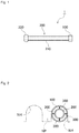
FIG. 1 is a plan view of an entire structure of a nasal cavity insertion device set. -
FIG. 2 is a schematic diagram showing a state that the nasal cavity insertion device set shown inFIG. 1 is inserted into a nasal passage. -
FIG. 3 is a schematic diagram showing a state that a nasal cavity insertion device set inserted into a nasal passage. -
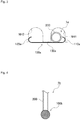
FIG. 4 is a plan view of a nasal cavity insertion device set in accordance with the present invention. -
FIG. 5 is a perspective view of a nasal cavity insertion device set according to a reference example. -
- 1, 1a, 1b Nasal cavity insertion device set
- 100 Fixture (tubular contact portion)
- 100a Fixture
- 110a First curved portion (first contact portion)
- 120a Second curved portion (second contact portion)
- 130a Coupling portion
- 100b Fixture (swell portion)
- 200 Nasal cavity insertion tube
- As shown in
FIG. 1 , a nasal cavity insertion device set 1 according to an embodiment of the present invention mainly includes a nasalcavity insertion tube 200 and a nasal cavity insertion device fixture (hereinafter simply referred to as "a fixture" on an as-needed basis) 100 for fixing the nasalcavity insertion tube 200 to the nose. - The nasal
cavity insertion tube 200 takes the form of a tubular body made of silicone resin or thermoplastic elastomer (of styrene series, vinyl chloride series, olefin series, urethane series, polyester-series, etc.), and is formed such that it can be extended from a nasal passage to the pharynx. The nasalcavity insertion tube 200 has: amain body portion 210 formed in a round tubular shape; and anexpansion portion 220 mounted to the tip end (pharynx side) of themain body portion 210. Themain body portion 210 serves a function of forming a flow path of the air when the nasalcavity insertion tube 200 is attached to the nasal cavity. On the other hand, theexpansion portion 220 is provided for expanding the pharynx, and expands the potentially narrowed/obstructed pharynx of a patient of sleep disorder. Further, in the present embodiment, thefixture 100 is mounted to the base end (nasal passage side) of the nasalcavity insertion tube 200. - As shown in
FIG. 2 , thefixture 100 according to the present embodiment makes contact with the inner surface of a nasal passage NH in order to fix the nasalcavity insertion tube 200 connected to thefixture 100. Thefixture 100 is a deflectable member and takes the form of a tubular body made of silicone resin. The outer diameter of thefixture 100 is greater than the inner diameter of the nasal passage NH so that the outer peripheral surface of thefixture 100 can make contact with the inner surface of the nasal passage NH. The size of the aforementioned inner diameter of the nasal passage NH depends on patients. Therefore, it is preferable to select the outer diameter of the fixture suitable for a patient on an as-needed basis. When inserted into the nasal passage NH, thefixture 100 is inserted into the nasal passage NH while the diameter thereof is reduced by compression. In turn, thefixture 100 inserted into the nasal passage NH is restored to the original shape thereof, and the outer peripheral surface thereof makes contact with the inner surface of the nasal passage NH (including the inner surface of the nasal wing) with a predetermined contact force. In other words, in the present embodiment, the nasalcavity insertion tube 200 is fixed by means of a force of expanding the nasal passage NH from the inside of the nasal passage NH. Thefixture 100 is thereby fixed to the inside of the nasal passage NH. - The nasal
cavity insertion tube 200 is disposed inside thetubular fixture 100. In short, in the present embodiment, a dual-nested tubular structure is formed by thefixture 100 and the nasalcavity insertion tube 200. A plurality of holdingportions 300 are mounted between thefixture 100 and the nasalcavity insertion tube 200. Thefixture 100 and the nasalcavity insertion tube 200 are disposed through a predetermined interval by the holdingportions 300. An air flow path can be reliably produced by thus disposing thefixture 100 and the nasalcavity insertion tube 200 through the predetermined interval. As a result, hindrance to the respiration of a patient by thefixture 100 and the nasalcavity insertion tube 200 can be suppressed. The holdingportions 300 take the form of elastic bodies for outwardly urging thefixture 100, and are composed of springs or rubber parts. - First, the
expansion portion 220 of the nasalcavity insertion tube 200 is gradually inserted to reach the pharynx. Then, thefixture 100 is inserted into the nasal passage NH. At this time, thefixture 100 is inserted into the nasal passage NH while the diameter thereof is reduced. When the insertion of thefixture 100 into the nasal passage NH is finished, thefixture 100 is restored to the original shape thereof and the outer peripheral surface of thefixture 100 makes contact with the inner surface of the nasal passage NH. Accordingly, the nasalcavity insertion tube 200 is fixed to the nasal passage NH by means of the force of expanding the nasal passage NH, i.e., the force applied by thefixture 100. - In removing the
fixture 100, it is only required to simply hold thefixture 100 by the hand and pull it down. -
- (1) The
fixture 100 according to the first embodiment can fix the nasalcavity insertion tube 200 by means of the force of expanding the nasal passage NH from the inside of the nasal passage NH. Therefore, it is possible to prevent the displacement or detachment of the nasalcavity insertion tube 200 during the sleep of a patient of sleep disorder. Especially, in the present embodiment, the outer peripheral surface of thetubular fixture 100 makes contact with the inner peripheral surface of the nasal passage NH by means of surface contact. Therefore, the nasalcavity insertion tube 200 can be firmly fixed. - (2) Further, in the nasal cavity insertion device set, the
fixture 100 is disposed inside the nasal passage NH. Therefore, thefixture 100 can be prevented from standing out. - (3) Further, in the nasal cavity insertion device set 1, the attached position of the
fixture 100 is the nose. Therefore, a user can attach thefixture 100 thereto by oneself. - (4) Further, the
fixture 100 is formed in a tubular shape that allows the air to pass therethrough. Therefore, hindrance to the respiration of a patient by thefixture 100 can be suppressed. - (5) Further, in the nasal cavity insertion device 1, the nasal
cavity insertion tube 200 can be accommodated inside thetubular fixture 100. Therefore, a single nasal passage can be commonly used as the nasal passage NH into which the nasalcavity insertion tube 200 is inserted and the nasal passage NH into which thefixture 100 is inserted. A normal nasal cavity, free from occurrence of the obstruction of the pharynx, can be thereby kept open. Therefore, hindrance to the respiration of a patient by thefixture 100 can be suppressed. - (6) Further, in the nasal cavity insertion device set 1, the nasal
cavity insertion tube 200 is accommodated inside thetubular fixture 100. Therefore, the nasalcavity insertion tube 200 can be prevented from standing out. Accordingly, a patient can use the nasalcavity insertion tube 200 and the nasal cavity insertion device set 1 without hesitation. - As shown in
FIG. 3 , a nasal cavity insertion device set 1a according to an example includes the nasalcavity insertion tube 200 and afixture 100a for fixing the nasalcavity insertion tube 200. The nasalcavity insertion tube 200 is similar to that in the first embodiment. Therefore, the explanation thereof will not be hereinafter made. - As shown in
FIG. 3 , thefixture 100a makes contact with both of the inner surface of a nasal passage NH1 and that of a nasal passage NH2 in order to fix the nasalcavity insertion tube 200 to be connected to thefixture 100a. Thefixture 100a is a flat spring and has: a firstcurved portion 110a making contact with the inner surface of the nasal passage NH1 into which the nasalcavity insertion tube 200 is inserted; a secondcurved portion 120a making contact with the inner surface of the nasal passage NH2 that is different from the nasal passage NH1; and acoupling portion 130a coupling the firstcurved portion 110a and the secondcurved portion 120a. Thecoupling portion 130a causes the firstcurved portion 110a to make contact with the inner surface of one nasal wing forming the nasal passage NH1 with a predetermined contact force, while causing the secondcurved portion 120a to make contact with the inner surface of the other nasal wing forming the nasal passage NH2. In other words, thefixture 100a is set such that it is pressed against and supported between the inner surfaces of the both nasal wings. It should be noted that thefixture 100a, taking the form of the flat spring, may be made of resin, or alternatively, may be made of metal. - The first
curved portion 110a is curved for making contact with the inner surface of the nasal passage NH1, while the secondcurved portion 120a is curved for making contact with the inner surface of the nasal passage NH2. Damage of the inner surfaces of the nasal passages NH1 and NH2 can be prevented by thus curving the firstcurved portion 110a and the secondcurved portion 120a. It should be noted that the length of thecoupling portion 130a may be adjustable so that the firstcurved portion 110a and the secondcurved portion 120a can be located closer to or away from each other. When the length of thecoupling portion 130a is designed to be adjustable, thefixture 100a can be fixed regardless of the size of the nose of a patient. - In the present embodiment, the
fixture 100a and the nasalcavity insertion tube 200 may be joined by means of welding, or alternatively, by means of adhesion. - In the present embodiment, the first
curved portion 110a and the secondcurved portion 120a respectively press the inner surfaces located away from a nasal bridge NP within the nasal passages NH1 and NH2. In other words, thefixture 100a is pressed against and supported by the both nasal wings. At this time, thefixture 100a as the flat spring exerts an elastic force, and is thereby fixed with a predetermined contact force. - First, the
expansion portion 220 of the nasalcavity insertion tube 200 is gradually inserted to reach the pharynx. Then, the firstcurved portion 110a of thefixture 100a is inserted into the nasal passage NH1, while the secondcurved portion 120a is inserted into the nasal passage NH2. Accordingly, the firstcurved portion 110a presses the inner surface of the nasal passage NH1 (the inner surface of the nasal wing forming the nasal passage NH1) with a predetermined contact force, while the secondcurved portion 120a presses the inner surface of the nasal passage NH2 (the inner surface of the nasal wing forming the nasal passage NH2) with a predetermined contact force. As a result, thefixture 100a is set such that it is pressed against and supported by the both nasal wings. Accordingly, the nasalcavity insertion tube 200 mounted to thefixture 100a is fixed. - In removing the
fixture 100a, it is only required to simply hold thefixture 100a by the hand and pull it down. -
- (1) The
fixture 100a can fix the nasalcavity insertion tube 200 by means of the force of expanding the nasal passages NH from the inside of the nasal passages NH. Therefore, it is possible to prevent the displacement or detachment of the nasalcavity insertion tube 200 during the sleep of a patient of sleep disorder. Especially, as to thefixture 100a according to the second embodiment, thefixture 100a is fixed by the both nasal passages NH1 and NH2. Therefore, thefixture 100a and the nasalcavity insertion tube 200 mounted thereto can be firmly fixed. - (2) Further, in the nasal cavity insertion device set 1a, the
curved portions fixture 100a are respectively disposed inside the nasal passages NH1 and NH2. Therefore, thefixture 100a can be prevented from standing out. - (3) Further, in the nasal cavity insertion device set 1a, the attached position of the
fixture 100a is the nose. Therefore, a user can attach thefixture 100a to the nose by oneself. - (4) Further, in the nasal
cavity insertion device 1a, thefixture 100a, having the firstcurved portion 110a, the secondcurved portion 120a and thecoupling portion 130a, can be formed by the single flat spring. In other words, thefixture 100a can be simply structured. Accordingly, in reusing thefixture 100a, thefixture 100a can be easily cleaned and can be used in a sanitary manner. - As shown in
FIG. 4 , a nasal cavity insertion device set 1b according to an example includes the nasalcavity insertion tube 200 and afixture 100b for fixing the nasalcavity insertion tube 200. The nasalcavity insertion tube 200 is similar to that in the first embodiment. Therefore, the explanation thereof will not be hereinafter made. - As shown in
FIG. 4 , thefixture 100b makes contact with the inner surface of the nasal passage NH (seeFIG. 2 , this is similarly applied in the following) in order to fix the nasalcavity insertion tube 200 connected to thefixture 100b. Thefixture 100b is a reticular member with a roughly spherical contour, and is swelled on the tip end of the nasalcavity insertion tube 200. The outer diameter of the roughlyspherical fixture 100b is greater than the inner diameter of the nasal passage. The size of the aforementioned inner diameter of the nasal passage NH depends on patients. Therefore, it is preferable to select the outer diameter of the fixture suitable for a patient on an as-needed basis. Further, in the present embodiment, thefixture 100b can be increased and reduced in the diameter thereof. When inserted into the nasal passage NH, thefixture 100b is inserted into the nasal passage NH while the diameter thereof is reduced. In turn, thefixture 100b inserted into the nasal passage NH is restored to the original shape thereof, and the outer peripheral surface thereof makes contact with the inner surface of the nasal passage NH (including the inner surface of the nasal wing) with a predetermined contact force. In other words, in the present embodiment, the nasalcavity insertion tube 200 is fixed by means of the force of expanding the nasal passage NH from the inside of the nasal passage NH. Thefixture 100b is thereby fixed to the inside of the nasal passage NH. - First, the
expansion portion 220 of the nasalcavity insertion tube 200 is gradually inserted to reach the pharynx. Then, thefixture 100b is inserted into the nasal passage NH. At this time, thefixture 100b is inserted into the nasal passage NH while the diameter thereof is reduced. When the insertion of thefixture 100b into the nasal passage NH is finished, thefixture 100b is restored to the original shape thereof and the outer peripheral surface of thefixture 100b makes contact with the inner surface of the nasal passage NH. Accordingly, the nasalcavity insertion tube 200 is fixed to the nasal passage NH by means of the force of expanding the nasal passage NH, i.e., the force applied by thefixture 100b. - In removing the
fixture 100b, it is only required to simply hold thefixture 100b by the hand and pull it down. -
- (1) The
fixture 100b can fix the nasalcavity insertion tube 200 by means of the force of expanding the nasal passage NH from the inside of the nasal passages NH. Therefore, it is possible to prevent the displacement or detachment of the nasalcavity insertion tube 200 during the sleep of a patient of sleep disorder. Especially, in the present embodiment, the reticular portion of thefixture 100b makes contact with the inner peripheral surface of the nasal cavity at multiple points. Therefore, thefixture 100b and the nasalcavity insertion tube 200 mounted to thefixture 100b can be firmly fixed. - (2) Further, in the nasal cavity insertion device set 1b, the
fixture 100b is disposed inside the nasal passage NH. Therefore, thefixture 100b can be prevented from standing out. - (3) Further, in the nasal cavity insertion device set 1b, the attached position of the
fixture 100b is the nose. Therefore, a user can attach thefixture 100b to the nose by oneself. - (4) Further, the
fixture 100b according to this embodiment is the reticular member that allows the air to pass therethrough. Therefore, even when inserted into the nasal passage NH, hindrance to the respiration of a patient by thefixture 100b can be suppressed. - As a reference example of the present invention, the inventors of the present application propose a nasal cavity
insertion device set 1f as shown inFIG. 5 . The nasal cavity insertion device set 1f includes the nasalcavity insertion tube 200 and anadhesive sheet 100f mounted to the base end of the nasalcavity insertion tube 200. The present nasalcavity insertion tube 200 is similar to the aforementioned nasalcavity insertion tube 200 according to the first embodiment. Therefore, the explanation thereof will not be hereinafter made. Further, in the reference example, theadhesive sheet 100f is adhered to the nose. Accordingly, the nasalcavity insertion tube 200 attached to theadhesive sheet 100f is fixed to the nose. - The embodiments and the practical example of the present invention have been explained above based on the drawings. However, it should be understood that the specific configuration should not be limited to the embodiments. The scope of the present invention is represented by claims.
- To prevent the fixture from standing out in wearing of the fixture, the color of the fixture may be transparent, the color of skin, pink, or black, although having not been mentioned in the aforementioned embodiments.
- Further, silicone resin has been exemplified as the materials of the
fixture 100 and the nasalcavity insertion tube 200 in the first embodiment. However, the materials related to the present invention is not limited to this, and other than silicone resin, the following materials can be applied. Specific examples are: ABS resin (acrylonitrile-butadiene-styrene); butadiene-styrene rubber; polyester copolymer; ethylene-propylene rubber (ethylene-propylene-terpolymer rubber); EVA resin (ethylene-vinylacetate copolymer); high-density polyethylene; high-density polypropylene; impact-resistant polystyrene; low-density polyethylene; methylmetacrylate-acrylonitrile-butadiene-styrene copolymer; chloroprene rubber; nitrilebutadiene rubber; polyamide resin; PETG resin; polyacetal resin; polybutyleneterephthalate resin; polycarbonate resin; polyethersulfone resin; polyethylene resin; polyethyleneterephthalate resin; polyimide resin; isobutylene-isoprene copolymer; polypropylene resin; polystyrene resin; polysulfone resin; polytetrafluoroethylene resin; polyurethane resin; polyvinylacetate resin; polyvinylchloride resin; styrene-butadiene resin; styrene-butadiene rubber; acrylic modified silicone resin; and one-component RTV (Room Temperature Vulcanizable) rubber. - The fixture and the nasal cavity insertion device set according to the present invention are characterized in that the displacement or detachment of the nasal cavity insertion tube can be prevented during the sleep of a patient of sleep disorder.
Claims (2)
- A nasal cavity insertion device set (1b), comprising:a device (200) to be inserted into a nasal cavity, anda nasal cavity insertion device fixture (100b) configured to fix said device (200) to be inserted by means of a force of expanding a nasal passage from inside the nasal passage, and to make contact with at least an inner surface of a nasal wing, the nasal cavity insertion device fixture (100b) comprising a swell portion whose outer peripheral surface is configured to make contact with an inner surface of the nasal passage,characterized in that the swell portion is a reticular member that allows air to pass therethrough; andthe nasal cavity insertion device fixture (100b) is attached to the tip end of the device (200) to be inserted into the nasal cavity.
- The nasal cavity insertion device set (1b) recited in claim 1, wherein the swell portion has a roughly spherical contour.
Applications Claiming Priority (2)
| Application Number | Priority Date | Filing Date | Title |
|---|---|---|---|
| JP2011108839A JP5211386B2 (en) | 2011-05-13 | 2011-05-13 | Nasal cavity insertion device fixture and nasal cavity insertion device set including the nasal cavity insertion device fixture |
| PCT/JP2012/003128 WO2012157243A1 (en) | 2011-05-13 | 2012-05-14 | Clip for nasal intubation device and nasal intubation device set provided with said clip |
Publications (3)
| Publication Number | Publication Date |
|---|---|
| EP2711040A1 EP2711040A1 (en) | 2014-03-26 |
| EP2711040A4 EP2711040A4 (en) | 2014-11-05 |
| EP2711040B1 true EP2711040B1 (en) | 2016-04-27 |
Family
ID=47176595
Family Applications (1)
| Application Number | Title | Priority Date | Filing Date |
|---|---|---|---|
| EP12785308.3A Not-in-force EP2711040B1 (en) | 2011-05-13 | 2012-05-14 | Clip for nasal intubation device |
Country Status (6)
| Country | Link |
|---|---|
| US (1) | US20140094840A1 (en) |
| EP (1) | EP2711040B1 (en) |
| JP (1) | JP5211386B2 (en) |
| CN (1) | CN103533978A (en) |
| ES (1) | ES2579617T3 (en) |
| WO (1) | WO2012157243A1 (en) |
Families Citing this family (7)
| Publication number | Priority date | Publication date | Assignee | Title |
|---|---|---|---|---|
| CN103816002A (en) * | 2014-03-06 | 2014-05-28 | 王震东 | Woven type nickel-titanium alloy nose support frame |
| JP6307310B2 (en) * | 2014-03-10 | 2018-04-04 | 株式会社無有 | Nasal moisturizer |
| CN106693130A (en) * | 2015-08-20 | 2017-05-24 | 中山贝尔思特制锁有限公司 | Assisted respiration catheter and production process thereof |
| CN109171633A (en) * | 2018-09-29 | 2019-01-11 | 郑州大学第附属医院 | The medical gastroscope device of gastroenterology |
| JP2022524103A (en) | 2019-03-08 | 2022-04-27 | メビオン・メディカル・システムズ・インコーポレーテッド | Irradiation by column and generation of treatment plan for it |
| KR102600486B1 (en) * | 2021-08-04 | 2023-11-08 | 최승영 | Nasal dilator devices |
| EP4494683A4 (en) | 2022-03-18 | 2026-01-14 | Nastent Inc | DEVICE FOR INSERTION IN THE NASAL CADUM |
Family Cites Families (22)
| Publication number | Priority date | Publication date | Assignee | Title |
|---|---|---|---|---|
| US3915173A (en) * | 1974-07-08 | 1975-10-28 | Ansur Inc | Intubation device for the inhalation of gasses |
| US4887597A (en) * | 1988-07-14 | 1989-12-19 | Holland Bruce K | Nose plug |
| RU1768142C (en) * | 1989-03-29 | 1992-10-15 | Ярославский Межотраслевой Научно-Технический Центр | Device for therapy of sinuitis |
| US5105807A (en) * | 1991-02-26 | 1992-04-21 | Alternative Medical Products, Inc. | Device and methods for securing nasal tubing |
| US5931852A (en) * | 1997-06-04 | 1999-08-03 | Brennan; H. George | Nose airway device |
| US5895409A (en) * | 1997-09-16 | 1999-04-20 | Mehdizadeh; Hamid | Nasal dilator |
| WO2000009192A1 (en) * | 1998-08-17 | 2000-02-24 | Kazuhiro Noda | Operation balloon |
| FR2804330B1 (en) * | 2000-02-01 | 2003-01-10 | Georges Boussignac | RESPIRATORY ASSISTANCE APPARATUS |
| DK1549379T3 (en) * | 2002-09-18 | 2014-01-20 | Asap Breathe Assist Pty Ltd | Nasal dilatation device |
| AU2004100927B4 (en) * | 2004-11-01 | 2005-03-24 | Richard Benson | Snorenomore (anti-snoring device) |
| JP2008149089A (en) * | 2006-12-19 | 2008-07-03 | New Wave Medical:Kk | Catheter for nasal cavity dilation |
| JP2009072581A (en) * | 2007-08-30 | 2009-04-09 | Ist Corp | Obstructive sleep apnea syndrome elimination tube |
| JP2009072582A (en) * | 2007-08-30 | 2009-04-09 | Ist Corp | Obstructive sleep apnea syndrome resolver |
| CN201120028Y (en) * | 2007-11-13 | 2008-09-24 | 孙丽霞 | Medical oxygen uptake rhinobyon |
| US20100042134A1 (en) * | 2008-04-18 | 2010-02-18 | Abraham Wien | Nostril dilator |
| NZ589634A (en) * | 2008-06-04 | 2012-09-28 | Resmed Ltd | A mask to apply positive airway pressure (PAP) for the treatment of a sleep disorder that attaches to the face |
| US8246647B2 (en) * | 2008-11-14 | 2012-08-21 | Abraham Wien | Nostril dilator |
| JP5481065B2 (en) * | 2008-12-26 | 2014-04-23 | 富士フイルム株式会社 | Endoscope insertion guide |
| JP5380067B2 (en) * | 2008-12-26 | 2014-01-08 | 富士フイルム株式会社 | Endoscope insertion aid |
| WO2010113305A1 (en) * | 2009-04-01 | 2010-10-07 | 株式会社アイ.エス.テイ | Tube for resolving obstructive sleep apnea syndrome |
| JP5061325B2 (en) * | 2010-03-05 | 2012-10-31 | セブン ドリーマーズ ラボラトリーズ,インコーポレイテッド | Pharyngeal dilation device |
| US9724228B2 (en) * | 2010-03-05 | 2017-08-08 | Seven Dreamers Laboratories, Inc. | Nasal cavity insertion device fixture and nasal cavity insertion device set including the same |
-
2011
- 2011-05-13 JP JP2011108839A patent/JP5211386B2/en not_active Expired - Fee Related
-
2012
- 2012-05-14 US US14/117,544 patent/US20140094840A1/en not_active Abandoned
- 2012-05-14 ES ES12785308.3T patent/ES2579617T3/en active Active
- 2012-05-14 EP EP12785308.3A patent/EP2711040B1/en not_active Not-in-force
- 2012-05-14 CN CN201280023393.7A patent/CN103533978A/en active Pending
- 2012-05-14 WO PCT/JP2012/003128 patent/WO2012157243A1/en not_active Ceased
Also Published As
| Publication number | Publication date |
|---|---|
| EP2711040A4 (en) | 2014-11-05 |
| WO2012157243A1 (en) | 2012-11-22 |
| JP2012239478A (en) | 2012-12-10 |
| US20140094840A1 (en) | 2014-04-03 |
| ES2579617T3 (en) | 2016-08-12 |
| EP2711040A1 (en) | 2014-03-26 |
| CN103533978A (en) | 2014-01-22 |
| JP5211386B2 (en) | 2013-06-12 |
Similar Documents
| Publication | Publication Date | Title |
|---|---|---|
| EP2711040A1 (en) | Clip for nasal intubation device and nasal intubation device set provided with said clip | |
| ES2620278T3 (en) | Nasal dilator | |
| US9492309B2 (en) | Nasal cavity insertion device | |
| RU2388501C2 (en) | Nasal dilatant and versions of its application | |
| US10492932B2 (en) | Device for splinting a cavity, organ duct and/or vessel | |
| CN107106804B (en) | Adaptive buckling member in a patient interface device | |
| US9724228B2 (en) | Nasal cavity insertion device fixture and nasal cavity insertion device set including the same | |
| AU2018204295A1 (en) | A nasal cannula, conduit and securement system | |
| JP2010509949A (en) | Nasal dilator | |
| EP2964166A1 (en) | Adhesive devices and methods for improving breathing and/or sleep using such devices | |
| JP2010246832A (en) | Breathing aid | |
| ES2787209T3 (en) | Nasal dilator | |
| EP2734149B1 (en) | Devices and methods for treating sleep disordered breathing | |
| CN103476447B (en) | Patient interface device including the decompression part for deformable component | |
| US20070021773A1 (en) | Nasal-dilating device for a constricted nostril | |
| JP4982047B2 (en) | Obstructive sleep apnea syndrome resolver | |
| JP4536013B2 (en) | Respiratory aid | |
| CN204352406U (en) | Air filtering device arranged in nasal cavity | |
| KR101088301B1 (en) | Assistant apparatus for oral treatment | |
| CN224099845U (en) | A type of nasal air conditioner | |
| KR101088297B1 (en) | Assistant apparatus for oral treatment | |
| KR101088300B1 (en) | Breathing filter and assistant apparatus for oral treatment having the same | |
| EP2923679B1 (en) | Nasal device | |
| KR101088298B1 (en) | Assistant apparatus for oral treatment | |
| CN115025350A (en) | Medical flexible reinforced damage-proof nasopharyngeal airway |
Legal Events
| Date | Code | Title | Description |
|---|---|---|---|
| PUAI | Public reference made under article 153(3) epc to a published international application that has entered the european phase |
Free format text: ORIGINAL CODE: 0009012 |
|
| 17P | Request for examination filed |
Effective date: 20131211 |
|
| AK | Designated contracting states |
Kind code of ref document: A1 Designated state(s): AL AT BE BG CH CY CZ DE DK EE ES FI FR GB GR HR HU IE IS IT LI LT LU LV MC MK MT NL NO PL PT RO RS SE SI SK SM TR |
|
| DAX | Request for extension of the european patent (deleted) | ||
| A4 | Supplementary search report drawn up and despatched |
Effective date: 20141009 |
|
| RIC1 | Information provided on ipc code assigned before grant |
Ipc: A61M 16/04 20060101AFI20141002BHEP Ipc: A61M 16/06 20060101ALI20141002BHEP Ipc: A61F 5/08 20060101ALI20141002BHEP Ipc: A61F 5/56 20060101ALI20141002BHEP |
|
| RAP1 | Party data changed (applicant data changed or rights of an application transferred) |
Owner name: SEVEN DREAMERS LABORATORIES, INC. |
|
| GRAP | Despatch of communication of intention to grant a patent |
Free format text: ORIGINAL CODE: EPIDOSNIGR1 |
|
| INTG | Intention to grant announced |
Effective date: 20151117 |
|
| GRAS | Grant fee paid |
Free format text: ORIGINAL CODE: EPIDOSNIGR3 |
|
| GRAA | (expected) grant |
Free format text: ORIGINAL CODE: 0009210 |
|
| AK | Designated contracting states |
Kind code of ref document: B1 Designated state(s): AL AT BE BG CH CY CZ DE DK EE ES FI FR GB GR HR HU IE IS IT LI LT LU LV MC MK MT NL NO PL PT RO RS SE SI SK SM TR |
|
| REG | Reference to a national code |
Ref country code: GB Ref legal event code: FG4D |
|
| REG | Reference to a national code |
Ref country code: CH Ref legal event code: EP |
|
| REG | Reference to a national code |
Ref country code: AT Ref legal event code: REF Ref document number: 794050 Country of ref document: AT Kind code of ref document: T Effective date: 20160515 |
|
| REG | Reference to a national code |
Ref country code: IE Ref legal event code: FG4D |
|
| REG | Reference to a national code |
Ref country code: DE Ref legal event code: R096 Ref document number: 602012017808 Country of ref document: DE |
|
| REG | Reference to a national code |
Ref country code: FR Ref legal event code: PLFP Year of fee payment: 5 |
|
| REG | Reference to a national code |
Ref country code: ES Ref legal event code: FG2A Ref document number: 2579617 Country of ref document: ES Kind code of ref document: T3 Effective date: 20160812 |
|
| REG | Reference to a national code |
Ref country code: LT Ref legal event code: MG4D |
|
| PG25 | Lapsed in a contracting state [announced via postgrant information from national office to epo] |
Ref country code: BE Free format text: LAPSE BECAUSE OF NON-PAYMENT OF DUE FEES Effective date: 20160531 |
|
| REG | Reference to a national code |
Ref country code: NL Ref legal event code: MP Effective date: 20160427 |
|
| REG | Reference to a national code |
Ref country code: AT Ref legal event code: MK05 Ref document number: 794050 Country of ref document: AT Kind code of ref document: T Effective date: 20160427 |
|
| PG25 | Lapsed in a contracting state [announced via postgrant information from national office to epo] |
Ref country code: NL Free format text: LAPSE BECAUSE OF FAILURE TO SUBMIT A TRANSLATION OF THE DESCRIPTION OR TO PAY THE FEE WITHIN THE PRESCRIBED TIME-LIMIT Effective date: 20160427 |
|
| PG25 | Lapsed in a contracting state [announced via postgrant information from national office to epo] |
Ref country code: NO Free format text: LAPSE BECAUSE OF FAILURE TO SUBMIT A TRANSLATION OF THE DESCRIPTION OR TO PAY THE FEE WITHIN THE PRESCRIBED TIME-LIMIT Effective date: 20160727 Ref country code: PL Free format text: LAPSE BECAUSE OF FAILURE TO SUBMIT A TRANSLATION OF THE DESCRIPTION OR TO PAY THE FEE WITHIN THE PRESCRIBED TIME-LIMIT Effective date: 20160427 Ref country code: FI Free format text: LAPSE BECAUSE OF FAILURE TO SUBMIT A TRANSLATION OF THE DESCRIPTION OR TO PAY THE FEE WITHIN THE PRESCRIBED TIME-LIMIT Effective date: 20160427 Ref country code: LT Free format text: LAPSE BECAUSE OF FAILURE TO SUBMIT A TRANSLATION OF THE DESCRIPTION OR TO PAY THE FEE WITHIN THE PRESCRIBED TIME-LIMIT Effective date: 20160427 |
|
| PG25 | Lapsed in a contracting state [announced via postgrant information from national office to epo] |
Ref country code: AT Free format text: LAPSE BECAUSE OF FAILURE TO SUBMIT A TRANSLATION OF THE DESCRIPTION OR TO PAY THE FEE WITHIN THE PRESCRIBED TIME-LIMIT Effective date: 20160427 Ref country code: PT Free format text: LAPSE BECAUSE OF FAILURE TO SUBMIT A TRANSLATION OF THE DESCRIPTION OR TO PAY THE FEE WITHIN THE PRESCRIBED TIME-LIMIT Effective date: 20160829 Ref country code: LV Free format text: LAPSE BECAUSE OF FAILURE TO SUBMIT A TRANSLATION OF THE DESCRIPTION OR TO PAY THE FEE WITHIN THE PRESCRIBED TIME-LIMIT Effective date: 20160427 Ref country code: RS Free format text: LAPSE BECAUSE OF FAILURE TO SUBMIT A TRANSLATION OF THE DESCRIPTION OR TO PAY THE FEE WITHIN THE PRESCRIBED TIME-LIMIT Effective date: 20160427 Ref country code: HR Free format text: LAPSE BECAUSE OF FAILURE TO SUBMIT A TRANSLATION OF THE DESCRIPTION OR TO PAY THE FEE WITHIN THE PRESCRIBED TIME-LIMIT Effective date: 20160427 Ref country code: GR Free format text: LAPSE BECAUSE OF FAILURE TO SUBMIT A TRANSLATION OF THE DESCRIPTION OR TO PAY THE FEE WITHIN THE PRESCRIBED TIME-LIMIT Effective date: 20160728 Ref country code: SE Free format text: LAPSE BECAUSE OF FAILURE TO SUBMIT A TRANSLATION OF THE DESCRIPTION OR TO PAY THE FEE WITHIN THE PRESCRIBED TIME-LIMIT Effective date: 20160427 |
|
| PG25 | Lapsed in a contracting state [announced via postgrant information from national office to epo] |
Ref country code: BE Free format text: LAPSE BECAUSE OF FAILURE TO SUBMIT A TRANSLATION OF THE DESCRIPTION OR TO PAY THE FEE WITHIN THE PRESCRIBED TIME-LIMIT Effective date: 20160427 |
|
| REG | Reference to a national code |
Ref country code: CH Ref legal event code: PL |
|
| REG | Reference to a national code |
Ref country code: DE Ref legal event code: R097 Ref document number: 602012017808 Country of ref document: DE |
|
| PG25 | Lapsed in a contracting state [announced via postgrant information from national office to epo] |
Ref country code: CH Free format text: LAPSE BECAUSE OF NON-PAYMENT OF DUE FEES Effective date: 20160531 Ref country code: RO Free format text: LAPSE BECAUSE OF FAILURE TO SUBMIT A TRANSLATION OF THE DESCRIPTION OR TO PAY THE FEE WITHIN THE PRESCRIBED TIME-LIMIT Effective date: 20160427 Ref country code: EE Free format text: LAPSE BECAUSE OF FAILURE TO SUBMIT A TRANSLATION OF THE DESCRIPTION OR TO PAY THE FEE WITHIN THE PRESCRIBED TIME-LIMIT Effective date: 20160427 Ref country code: LI Free format text: LAPSE BECAUSE OF NON-PAYMENT OF DUE FEES Effective date: 20160531 Ref country code: DK Free format text: LAPSE BECAUSE OF FAILURE TO SUBMIT A TRANSLATION OF THE DESCRIPTION OR TO PAY THE FEE WITHIN THE PRESCRIBED TIME-LIMIT Effective date: 20160427 Ref country code: CZ Free format text: LAPSE BECAUSE OF FAILURE TO SUBMIT A TRANSLATION OF THE DESCRIPTION OR TO PAY THE FEE WITHIN THE PRESCRIBED TIME-LIMIT Effective date: 20160427 Ref country code: MC Free format text: LAPSE BECAUSE OF FAILURE TO SUBMIT A TRANSLATION OF THE DESCRIPTION OR TO PAY THE FEE WITHIN THE PRESCRIBED TIME-LIMIT Effective date: 20160427 Ref country code: SK Free format text: LAPSE BECAUSE OF FAILURE TO SUBMIT A TRANSLATION OF THE DESCRIPTION OR TO PAY THE FEE WITHIN THE PRESCRIBED TIME-LIMIT Effective date: 20160427 |
|
| REG | Reference to a national code |
Ref country code: IE Ref legal event code: MM4A |
|
| PG25 | Lapsed in a contracting state [announced via postgrant information from national office to epo] |
Ref country code: SM Free format text: LAPSE BECAUSE OF FAILURE TO SUBMIT A TRANSLATION OF THE DESCRIPTION OR TO PAY THE FEE WITHIN THE PRESCRIBED TIME-LIMIT Effective date: 20160427 |
|
| PLBE | No opposition filed within time limit |
Free format text: ORIGINAL CODE: 0009261 |
|
| STAA | Information on the status of an ep patent application or granted ep patent |
Free format text: STATUS: NO OPPOSITION FILED WITHIN TIME LIMIT |
|
| 26N | No opposition filed |
Effective date: 20170130 |
|
| REG | Reference to a national code |
Ref country code: FR Ref legal event code: PLFP Year of fee payment: 6 |
|
| PG25 | Lapsed in a contracting state [announced via postgrant information from national office to epo] |
Ref country code: IE Free format text: LAPSE BECAUSE OF NON-PAYMENT OF DUE FEES Effective date: 20160514 Ref country code: SI Free format text: LAPSE BECAUSE OF FAILURE TO SUBMIT A TRANSLATION OF THE DESCRIPTION OR TO PAY THE FEE WITHIN THE PRESCRIBED TIME-LIMIT Effective date: 20160427 |
|
| REG | Reference to a national code |
Ref country code: FR Ref legal event code: PLFP Year of fee payment: 7 |
|
| PG25 | Lapsed in a contracting state [announced via postgrant information from national office to epo] |
Ref country code: CY Free format text: LAPSE BECAUSE OF FAILURE TO SUBMIT A TRANSLATION OF THE DESCRIPTION OR TO PAY THE FEE WITHIN THE PRESCRIBED TIME-LIMIT Effective date: 20160427 Ref country code: HU Free format text: LAPSE BECAUSE OF FAILURE TO SUBMIT A TRANSLATION OF THE DESCRIPTION OR TO PAY THE FEE WITHIN THE PRESCRIBED TIME-LIMIT; INVALID AB INITIO Effective date: 20120514 |
|
| PG25 | Lapsed in a contracting state [announced via postgrant information from national office to epo] |
Ref country code: MK Free format text: LAPSE BECAUSE OF FAILURE TO SUBMIT A TRANSLATION OF THE DESCRIPTION OR TO PAY THE FEE WITHIN THE PRESCRIBED TIME-LIMIT Effective date: 20160427 Ref country code: TR Free format text: LAPSE BECAUSE OF FAILURE TO SUBMIT A TRANSLATION OF THE DESCRIPTION OR TO PAY THE FEE WITHIN THE PRESCRIBED TIME-LIMIT Effective date: 20160427 Ref country code: LU Free format text: LAPSE BECAUSE OF NON-PAYMENT OF DUE FEES Effective date: 20160514 Ref country code: IS Free format text: LAPSE BECAUSE OF FAILURE TO SUBMIT A TRANSLATION OF THE DESCRIPTION OR TO PAY THE FEE WITHIN THE PRESCRIBED TIME-LIMIT Effective date: 20160427 Ref country code: MT Free format text: LAPSE BECAUSE OF NON-PAYMENT OF DUE FEES Effective date: 20160531 |
|
| PG25 | Lapsed in a contracting state [announced via postgrant information from national office to epo] |
Ref country code: BG Free format text: LAPSE BECAUSE OF FAILURE TO SUBMIT A TRANSLATION OF THE DESCRIPTION OR TO PAY THE FEE WITHIN THE PRESCRIBED TIME-LIMIT Effective date: 20160427 |
|
| PG25 | Lapsed in a contracting state [announced via postgrant information from national office to epo] |
Ref country code: AL Free format text: LAPSE BECAUSE OF FAILURE TO SUBMIT A TRANSLATION OF THE DESCRIPTION OR TO PAY THE FEE WITHIN THE PRESCRIBED TIME-LIMIT Effective date: 20160427 |
|
| PGFP | Annual fee paid to national office [announced via postgrant information from national office to epo] |
Ref country code: DE Payment date: 20190521 Year of fee payment: 8 Ref country code: IT Payment date: 20190527 Year of fee payment: 8 Ref country code: ES Payment date: 20190621 Year of fee payment: 8 |
|
| PGFP | Annual fee paid to national office [announced via postgrant information from national office to epo] |
Ref country code: FR Payment date: 20190523 Year of fee payment: 8 |
|
| PGFP | Annual fee paid to national office [announced via postgrant information from national office to epo] |
Ref country code: GB Payment date: 20190521 Year of fee payment: 8 |
|
| REG | Reference to a national code |
Ref country code: DE Ref legal event code: R119 Ref document number: 602012017808 Country of ref document: DE |
|
| GBPC | Gb: european patent ceased through non-payment of renewal fee |
Effective date: 20200514 |
|
| PG25 | Lapsed in a contracting state [announced via postgrant information from national office to epo] |
Ref country code: FR Free format text: LAPSE BECAUSE OF NON-PAYMENT OF DUE FEES Effective date: 20200531 Ref country code: GB Free format text: LAPSE BECAUSE OF NON-PAYMENT OF DUE FEES Effective date: 20200514 |
|
| PG25 | Lapsed in a contracting state [announced via postgrant information from national office to epo] |
Ref country code: DE Free format text: LAPSE BECAUSE OF NON-PAYMENT OF DUE FEES Effective date: 20201201 |
|
| REG | Reference to a national code |
Ref country code: ES Ref legal event code: FD2A Effective date: 20210930 |
|
| PG25 | Lapsed in a contracting state [announced via postgrant information from national office to epo] |
Ref country code: IT Free format text: LAPSE BECAUSE OF NON-PAYMENT OF DUE FEES Effective date: 20200514 |
|
| PG25 | Lapsed in a contracting state [announced via postgrant information from national office to epo] |
Ref country code: ES Free format text: LAPSE BECAUSE OF NON-PAYMENT OF DUE FEES Effective date: 20200515 |