JP2009072581A - Obstructive sleep apnea syndrome dissolving tube - Google Patents
Obstructive sleep apnea syndrome dissolving tube Download PDFInfo
- Publication number
- JP2009072581A JP2009072581A JP2008220069A JP2008220069A JP2009072581A JP 2009072581 A JP2009072581 A JP 2009072581A JP 2008220069 A JP2008220069 A JP 2008220069A JP 2008220069 A JP2008220069 A JP 2008220069A JP 2009072581 A JP2009072581 A JP 2009072581A
- Authority
- JP
- Japan
- Prior art keywords
- sleep apnea
- tube
- apnea syndrome
- obstructive sleep
- syndrome elimination
- Prior art date
- Legal status (The legal status is an assumption and is not a legal conclusion. Google has not performed a legal analysis and makes no representation as to the accuracy of the status listed.)
- Pending
Links
Images


Abstract
Description
本発明は、睡眠時に閉塞型睡眠時無呼吸症候群患者の上気道の咽頭部が閉塞することを防止する閉塞型睡眠時無呼吸症候群解消チューブに関する。 The present invention relates to an obstructive sleep apnea syndrome elimination tube that prevents the pharynx of the upper respiratory tract from becoming obstructed during sleep.
閉塞型睡眠時無呼吸症候群の患者は、睡眠時に上気道の咽頭部が筋肉の弛緩と肥満等との合併症で閉塞され、一時的な窒息(無呼吸、低呼吸)状態を断続的に繰り返す。このため、閉塞型睡眠時無呼吸症候群の患者は、高血圧症を患ったり脳血管及び心血管に障害を患ったりし、その結果、無呼吸又は低呼吸後に覚醒反応が繰り返す。この結果、閉塞型睡眠時無呼吸症候群の患者は、十分な睡眠がとれず、日中に眠気を催したり、日中に集中力や活力を欠いたりするようになる。また、閉塞型睡眠時無呼吸症候群の患者が自動車の運転をする場合には、その患者は居眠り運転で事故や重大事故等を起こしやすくなる。 In patients with obstructive sleep apnea syndrome, the pharynx of the upper respiratory tract is obstructed by complications such as muscle relaxation and obesity during sleep, and intermittent choking (apnea, hypopnea) is repeated intermittently. . For this reason, patients with obstructive sleep apnea syndrome suffer from hypertension or cerebrovascular and cardiovascular disorders, and as a result, the awakening reaction repeats after apnea or hypopnea. As a result, patients with obstructive sleep apnea syndrome may not be able to sleep adequately, and may become drowsy during the day or lack concentration or vitality during the day. In addition, when a patient with obstructive sleep apnea syndrome drives a car, the patient is likely to cause an accident or a serious accident or the like due to drowsy driving.
そこで、近年、閉塞型睡眠時無呼吸症候群を治療したり解消したりするための様々な提案がなされている。例えば、過去に「外部から適当な圧力の空気を鼻孔経由で咽頭部に送り、閉塞部分を空気圧で押し拡げて吸気のための気道を確保する」という方法(例えば、特許文献1参照)や「マウスピースを着用する」という方法等が提案されている。 Thus, in recent years, various proposals have been made to treat or eliminate obstructive sleep apnea syndrome. For example, in the past, a method of “sending air of appropriate pressure from the outside to the pharynx via the nostril and expanding the blockage portion with air pressure to secure an airway for inspiration” (see, for example, Patent Document 1) or “ A method of “wearing a mouthpiece” has been proposed.
前者のような空気加圧方式の治療方法を実施するためには、空気加圧装置が必要となる。しかし、空気加圧装置は、比較的大きいだけでなく重く、旅行等での持ち運びに向かない。また、空気加圧装置は、一般的に高価であり、閉塞型睡眠時無呼吸症候群の患者に大きな経済的負担を強いることになる。また、閉塞型睡眠時無呼吸症候群の患者が空気加圧装置を利用する場合、その患者は、空気加圧装置から送られてくる加圧空気が漏れないように鼻孔部分をマスクで完全に覆うと共にこのマスクと空気配送パイプとが外れないようにこのマスクと空気配送パイプとを頭部にヘッドバンドで固定しなければならない。睡眠時にこれらの部品を装着することは患者にとって苦痛である。また、空気加圧装置は、作動音がうるさく、患者本人のみならず周囲の人の睡眠を妨げることがある。さらに、冬季の使用時に室温が下がると、マスク内で呼気中の水分が凝集して水滴となり、患者の顔にかかって患者の睡眠を妨げることもある。 In order to carry out the treatment method of the air pressurization method like the former, an air pressurization apparatus is required. However, the air pressurizing apparatus is not only relatively large but also heavy, and is not suitable for carrying on travel. Air pressurizers are also generally expensive and impose a significant economic burden on patients with obstructive sleep apnea syndrome. When a patient with obstructive sleep apnea syndrome uses an air pressurization device, the patient completely covers the nostril portion with a mask so that the pressurized air sent from the air pressurization device does not leak. At the same time, the mask and the air delivery pipe must be fixed to the head with a headband so that the mask and the air delivery pipe do not come off. Wearing these components during sleep is painful for the patient. In addition, the air pressurizing device is noisy and may disturb sleep of not only the patient but also the surrounding people. Furthermore, when the room temperature decreases during winter use, the moisture in the breath aggregates in the mask to form water droplets, which may hit the patient's face and interfere with the patient's sleep.
一方、後者のような治療方法は、患者の症状が軽微な場合には一定の効果が得られるが、重症の患者には効果が期待できないことが多い。 On the other hand, the latter treatment method can achieve a certain effect when the patient's symptoms are minor, but cannot often be expected for a severe patient.
このような状況の中で、最近、「咽頭部から鼻孔部分に至る長さを有する柔軟なチューブと、チューブ内に挿通される柔軟なガイドワイヤーと、ガイドワイヤーの一端に設けられる弾性変形可能な網状筒体と、ガイドワイヤーの他端に設けられるストッパーとから構成される閉塞型睡眠時無呼吸症候群解消器」が提案されている(例えば、特許文献2参照)。患者がこの閉塞型睡眠時無呼吸症候群解消器を装着するには、患者は、先ず、ストッパーを引いて網状筒体をチューブに収容した状態にした後に、その状態の閉塞型睡眠時無呼吸症候群解消器を自身の鼻孔から挿入しその閉塞型睡眠時無呼吸症候群解消器を鼻腔に通して閉塞型睡眠時無呼吸症候群解消器のストッパー側の端部が鼻孔から少し出ている状態にする。その後、患者は、チューブのストッパー側の端部を一方の手で保持し、他方の手でストッパーがチューブの端部に当接するまでガイドワイヤーをチューブ内に押し込む。すると、チューブ内に収容されていた網状筒体がチューブから押し出され、網状筒体が患者の咽頭部において展開され咽頭部の気道を押し広げる。このように閉塞型睡眠時無呼吸症候群解消器は、確実な気道確保を行えると共に装着が簡単で患者本人及び周囲の人の睡眠時の邪魔になることもなく、しかも、小型軽量且つ安価で持ち運びも容易であり、非常に優れたものである。
本発明の課題は、従来の閉塞型睡眠時無呼吸症候群解消器具よりも安価で使いやすい閉塞型睡眠時無呼吸症候群解消器具を提供することにある。 An object of the present invention is to provide an obstructive sleep apnea syndrome eliminating device that is cheaper and easier to use than conventional obstructive sleep apnea syndrome resolving devices.
第1発明は、閉塞型睡眠時無呼吸症候群解消チューブである。なお、この閉塞型睡眠時無呼吸症候群解消チューブは、先端部が先細りの形状であることが好ましい。 The first invention is an obstructive sleep apnea syndrome elimination tube. The obstructive sleep apnea syndrome elimination tube preferably has a tapered tip.
この閉塞型睡眠時無呼吸症候群解消チューブは、鼻孔から鼻腔を経て咽頭部の気道を押し広げるようにして挿入される。このため、この閉塞型睡眠時無呼吸症候群解消チューブは、非常に簡易な構成でありながら非常に簡単に装着することができる。したがって、この閉塞型睡眠時無呼吸症候群解消チューブは、従来の閉塞型睡眠時無呼吸症候群解消器よりも安価で使いやすい。 The obstructive sleep apnea syndrome elimination tube is inserted so as to spread the airway of the pharynx from the nostril through the nasal cavity. For this reason, this obstructive sleep apnea syndrome elimination tube can be mounted very easily while having a very simple configuration. Therefore, the obstructive sleep apnea syndrome elimination tube is cheaper and easier to use than the conventional obstructive sleep apnea syndrome elimination device.
第2発明に係る閉塞型睡眠時無呼吸症候群解消チューブは、第1発明に係る閉塞型睡眠時無呼吸症候群解消チューブであって、外周面の全体又は一部にゲル物質が塗布される。なお、ここにいう「ゲル物質」とは、液体、特に水を包含する架橋高分子物質を意味する。また、このゲル物質は閉塞型睡眠時無呼吸症候群解消チューブの先端に塗布されるのが好ましい。 The obstructive sleep apnea syndrome elimination tube according to the second invention is the obstruction sleep apnea syndrome elimination tube according to the first invention, and the gel substance is applied to the whole or a part of the outer peripheral surface. Here, the “gel substance” means a crosslinked polymer substance including a liquid, particularly water. The gel substance is preferably applied to the tip of the obstructive sleep apnea syndrome elimination tube.
この閉塞型睡眠時無呼吸症候群解消チューブには、外周面の全体又は一部にゲル物質が塗布される。このため、この閉塞型睡眠時無呼吸症候群解消チューブは、装着時において閉塞型睡眠時無呼吸症候群の患者が感じる異物感(違和感)を軽減することができる。 In this obstructive sleep apnea syndrome elimination tube, a gel substance is applied to the whole or a part of the outer peripheral surface. For this reason, this obstructive sleep apnea syndrome elimination tube can reduce the foreign body feeling (discomfort) felt by the patient with obstructive sleep apnea syndrome when worn.
第3発明に係る閉塞型睡眠時無呼吸症候群解消チューブは、第1発明に係る閉塞型睡眠時無呼吸症候群解消チューブであって、外周面の全体又は一部に軟質ゴムが塗布される。 The obstructive sleep apnea syndrome elimination tube according to the third invention is the obstruction sleep apnea syndrome elimination tube according to the first invention, and a soft rubber is applied to the whole or a part of the outer peripheral surface.
この閉塞型睡眠時無呼吸症候群解消チューブには、外周面の全体又は一部に軟質ゴムが塗布される。このため、この閉塞型睡眠時無呼吸症候群解消チューブは、装着時において閉塞型睡眠時無呼吸症候群の患者が感じる異物感(違和感)を軽減することができる。 In this obstructive sleep apnea syndrome elimination tube, soft rubber is applied to the whole or a part of the outer peripheral surface. For this reason, this obstructive sleep apnea syndrome elimination tube can reduce the foreign body feeling (discomfort) felt by the patient with obstructive sleep apnea syndrome when worn.
第4発明に係る閉塞型睡眠時無呼吸症候群解消チューブは、第1発明から第3発明のいずれかに係る閉塞型睡眠時無呼吸症候群解消チューブであって、突起部を備える。突起部は、閉塞型睡眠時無呼吸症候群解消チューブの外周面から外側に延びる。なお、ここにいう「突起部」は、閉塞型睡眠時無呼吸症候群解消チューブ装着時に閉塞型睡眠時無呼吸症候群解消チューブが鼻孔に埋没してしまわないようにするためのものである。また、突起部は閉塞型睡眠時無呼吸症候群解消チューブの基端側に設けられるのが好ましい。また、突起部は、外周面から突起しない状態となることが可能であってもかまわない。 An obstructive sleep apnea syndrome elimination tube according to a fourth aspect of the present invention is the obstructive sleep apnea syndrome elimination tube according to any one of the first to third aspects of the invention, and includes a protrusion. The protrusion extends outward from the outer peripheral surface of the obstructive sleep apnea syndrome elimination tube. The “protrusions” here are for preventing the obstructive sleep apnea syndrome elimination tube from being buried in the nostrils when the obstruction sleep apnea syndrome elimination tube is attached. Moreover, it is preferable that a projection part is provided in the base end side of an obstruction type sleep apnea syndrome elimination tube. Further, the protrusion may be in a state where it does not protrude from the outer peripheral surface.
この閉塞型睡眠時無呼吸症候群解消チューブには、突起部が設けられる。このため、患者の睡眠中に閉塞型睡眠時無呼吸症候群解消チューブが患者の鼻孔に埋没してしまうことを避けることができる。 This obstructive sleep apnea syndrome elimination tube is provided with a protrusion. For this reason, it is possible to avoid the obstructive sleep apnea syndrome elimination tube being buried in the patient's nostril during the patient's sleep.
第5発明に係る閉塞型睡眠時無呼吸症候群解消チューブは、第1発明から第4発明のいずれかに係る閉塞型睡眠時無呼吸症候群解消チューブであって、全部又は一部が湾曲している。なお、かかる場合、閉塞型睡眠時無呼吸症候群解消チューブは人の鼻腔内の形状に沿って湾曲しているのが好ましい。 An obstructive sleep apnea syndrome elimination tube according to a fifth aspect of the present invention is the obstructive sleep apnea syndrome elimination tube according to any of the first to fourth aspects of the invention, all or part of which is curved. . In such a case, it is preferable that the obstructive sleep apnea syndrome elimination tube is curved along the shape of the human nasal cavity.
この閉塞型睡眠時無呼吸症候群解消チューブは、全部又は一部が湾曲している。このため、その湾曲形状を人の鼻腔内の形状に沿うようにすれば、この閉塞型睡眠時無呼吸症候群解消チューブは、装着時において閉塞型睡眠時無呼吸症候群の患者が感じる異物感(違和感)を軽減することができる。 This obstructive sleep apnea syndrome elimination tube is curved in whole or in part. For this reason, if the curved shape is made to conform to the shape in the human nasal cavity, this obstructive sleep apnea syndrome elimination tube will feel a foreign body feeling (discomfort) felt by a patient with obstructive sleep apnea syndrome when worn. ) Can be reduced.
第6発明に係る閉塞型睡眠時無呼吸症候群解消チューブは、第1発明から第5発明のいずれかに係る閉塞型睡眠時無呼吸症候群解消チューブであって、側壁を貫通する貫通孔を備える。なお、この貫通孔は閉塞型睡眠時無呼吸症候群解消チューブの先端側に設けるのが好ましい。また、貫通孔は、多ければ多い程通気性に優れるが、逆に強度が低下する。このため、貫通孔の大きさや数は通気性および強度の両面から検討する必要がある。 An obstructive sleep apnea syndrome elimination tube according to a sixth aspect of the present invention is the obstructive sleep apnea syndrome elimination tube according to any of the first to fifth aspects of the invention, and includes a through-hole penetrating the side wall. This through hole is preferably provided on the distal end side of the obstructive sleep apnea syndrome elimination tube. Further, the more through holes, the better the air permeability, but conversely the strength decreases. For this reason, it is necessary to examine the size and number of through holes from the viewpoints of air permeability and strength.
この閉塞型睡眠時無呼吸症候群解消チューブは、側壁を貫通する貫通孔を備える。このため、この閉塞型睡眠時無呼吸症候群解消チューブは、装着時において閉塞型睡眠時無呼吸症候群の患者が息苦しくなるのを軽減することができる。 The obstructive sleep apnea syndrome elimination tube includes a through-hole penetrating the side wall. For this reason, this obstructive sleep apnea syndrome elimination tube can reduce the difficulty of breathing in patients with obstructive sleep apnea syndrome when worn.
第7発明に係る閉塞型睡眠時無呼吸症候群解消チューブは、第1発明から第6発明のいずれかに係る閉塞型睡眠時無呼吸症候群解消チューブであって、ガイド部を備える。ガイド部は、扁平形状を呈しており、閉塞型睡眠時無呼吸症候群解消チューブの先端から突出するように延びている。なお、ガイド部は薄肉であることが好ましい。 An obstructive sleep apnea syndrome elimination tube according to a seventh aspect of the present invention is the obstructive sleep apnea syndrome elimination tube according to any of the first to sixth aspects of the invention, and includes a guide portion. The guide part has a flat shape and extends so as to protrude from the distal end of the obstructive sleep apnea syndrome elimination tube. The guide portion is preferably thin.
ところで、閉塞型睡眠時無呼吸症候群の患者は、気道閉塞時において肺側の気圧が低下している。したがって、閉塞型睡眠時無呼吸症候群の患者が予め閉塞型睡眠時無呼吸症候群解消チューブを鼻孔から入れガイド部を咽頭部に挿入した後に眠りにつけば、閉塞型睡眠時無呼吸症候群の患者が睡眠状態に入り気道閉塞状態となったときに咽頭部を挟む内外空間の気圧差によりガイド部が自動的に肺側に吸引され、それとともに閉塞型睡眠時無呼吸症候群解消チューブが自動的に咽頭部に挿入される。このため、この閉塞型睡眠時無呼吸症候群解消チューブは、閉塞型睡眠時無呼吸症候群の患者が睡眠状態に入る前までの嚥下(えんげ=つばを呑み込む時に気道が収縮する)時における異物感(違和感)を軽減することができる。 By the way, in patients with obstructive sleep apnea syndrome, the air pressure on the lung side is reduced when the airway is blocked. Therefore, if a patient with obstructive sleep apnea syndrome puts the obstructive sleep apnea syndrome elimination tube through the nostril and inserts the guide part into the pharynx before putting it to sleep, the patient with obstructive sleep apnea syndrome sleeps When the airway is blocked and the airway is blocked, the guide part is automatically aspirated to the lungs due to the pressure difference between the internal and external spaces that sandwich the pharynx, and the obstructive sleep apnea syndrome elimination tube is automatically Inserted into. For this reason, this obstructive sleep apnea syndrome elimination tube is a foreign body sensation during swallowing before the patient with obstructive sleep apnea syndrome enters sleep state (Discomfort) can be reduced.
第8発明に係る閉塞型睡眠時無呼吸症候群解消チューブは、第1発明から第6発明のいずれかに係る閉塞型睡眠時無呼吸症候群解消チューブであって、形態変形部およびガイド部を備える。形態変形部は、長手方向及び径方向に変形可能であって、閉塞型睡眠時無呼吸症候群解消チューブの先端に設けられる。なお、ここにいう「形態変形部」とは、例えば、非装着時において基端側に倒れるように形成された風船(バルーン)等である。ガイド部は、扁平形状を呈しており、形態変形部の先端から突出するように延びる。また、ガイド部は薄肉であることが好ましい。 An obstructive sleep apnea syndrome elimination tube according to an eighth aspect of the present invention is the obstructive sleep apnea syndrome elimination tube according to any of the first to sixth aspects of the invention, and includes a form deforming portion and a guide portion. The shape deformable portion can be deformed in the longitudinal direction and the radial direction, and is provided at the distal end of the obstructive sleep apnea syndrome elimination tube. In addition, the “form deforming portion” referred to here is, for example, a balloon formed so as to fall to the proximal end side when not attached. The guide part has a flat shape and extends so as to protrude from the tip of the form deforming part. Moreover, it is preferable that a guide part is thin.
ところで、閉塞型睡眠時無呼吸症候群の患者は、気道閉塞時において肺側の気圧が低下している。したがって、閉塞型睡眠時無呼吸症候群の患者が予め閉塞型睡眠時無呼吸症候群解消チューブを鼻孔から入れガイド部を咽頭部に挿入した後に眠りにつけば、閉塞型睡眠時無呼吸症候群の患者が睡眠状態に入り気道閉塞状態となったときに咽頭部を挟む内外空間の気圧差によりガイド部が自動的に肺側に吸引され、それとともに形態変形部が形態変形しながら自動的に咽頭部に挿入される。このため、この閉塞型睡眠時無呼吸症候群解消チューブは、閉塞型睡眠時無呼吸症候群の患者が睡眠状態に入る前までの嚥下(えんげ=つばを呑み込む時に気道が収縮する)時における異物感(違和感)を軽減することができるとともに咽頭部に食い込むことができ、睡眠中に患者が寝返りをうっても抜けにくくなる。 By the way, in patients with obstructive sleep apnea syndrome, the air pressure on the lung side is reduced when the airway is blocked. Therefore, if a patient with obstructive sleep apnea syndrome puts the obstructive sleep apnea syndrome elimination tube through the nostril and inserts the guide part into the pharynx before putting it to sleep, the patient with obstructive sleep apnea syndrome sleeps When the airway is blocked and the airway is blocked, the guide part is automatically sucked to the lungs due to the pressure difference between the internal and external spaces that sandwich the pharynx, and the deformed part is automatically inserted into the pharynx while deforming. Is done. For this reason, this obstructive sleep apnea syndrome elimination tube is a foreign body sensation during swallowing before the patient with obstructive sleep apnea syndrome enters sleep state (Uncomfortable feeling) can be reduced and the pharynx can be bitten, and even if the patient turns over during sleep, it becomes difficult to escape.
第9発明に係る閉塞型睡眠時無呼吸症候群解消チューブは、第1発明から第7発明のいずれかに係る閉塞型睡眠時無呼吸症候群解消チューブであって、外周面の全体又は一部に水膨潤樹脂が塗布される。なお、水膨潤樹脂が外周面の一部に塗布される場合、咽頭部の位置を考慮して水膨潤樹脂の塗布位置を決定する必要がある。また、閉塞型睡眠時無呼吸症候群解消チューブの外周面の全体にゲル物質が塗布される場合、水膨潤樹脂は塗布されない。しかし、閉塞型睡眠時無呼吸症候群解消チューブの外周面の一部にゲル物質が塗布される場合、水膨潤樹脂はゲル物質と重ならないように塗布され得る。かかる場合、ゲル物質が閉塞型睡眠時無呼吸症候群解消チューブの先端部に塗布され、先端部から少し離れた基端側の部分に水膨潤樹脂が塗布されるのが好ましい。また、水膨潤樹脂の塗布部分から基端側の部分にさらにゲル物質を塗布してもかまわない。また、閉塞型睡眠時無呼吸症候群解消チューブの外周面の全体に軟質ゴムが塗布される場合、水膨潤樹脂は軟質ゴムの上側(空気側)に塗布され得る。また、閉塞型睡眠時無呼吸症候群解消チューブの外周面の一部に軟質ゴムが塗布される場合、水膨潤樹脂は、軟質ゴムと重ならないように塗布され得る。かかる場合、軟質ゴムが閉塞型睡眠時無呼吸症候群解消チューブの先端部に塗布され、先端部の近傍部分に水膨潤樹脂が塗布されるのが好ましい。また、水膨潤樹脂の塗布部分から基端側の部分にさらに軟質ゴムを塗布してもかまわない。 The obstructive sleep apnea syndrome elimination tube according to the ninth aspect of the present invention is the obstructive sleep apnea syndrome elimination tube according to any of the first to seventh aspects of the present invention, wherein water is added to the whole or a part of the outer peripheral surface. A swelling resin is applied. In addition, when water swelling resin is apply | coated to a part of outer peripheral surface, it is necessary to determine the application position of water swelling resin in consideration of the position of a pharynx. Further, when the gel substance is applied to the entire outer peripheral surface of the obstructive sleep apnea syndrome elimination tube, the water swelling resin is not applied. However, when the gel substance is applied to a part of the outer peripheral surface of the obstructive sleep apnea syndrome elimination tube, the water swelling resin may be applied so as not to overlap the gel substance. In such a case, it is preferable that the gel substance is applied to the distal end portion of the obstructive sleep apnea syndrome elimination tube, and the water-swelling resin is applied to a proximal end portion slightly away from the distal end portion. Moreover, you may apply | coat a gel substance further to the part of a base end side from the application part of water swelling resin. When soft rubber is applied to the entire outer peripheral surface of the obstructive sleep apnea syndrome elimination tube, the water-swelling resin can be applied to the upper side (air side) of the soft rubber. Moreover, when a soft rubber is applied to a part of the outer peripheral surface of the obstructive sleep apnea syndrome elimination tube, the water-swelling resin may be applied so as not to overlap the soft rubber. In such a case, it is preferable that the soft rubber is applied to the distal end portion of the obstructive sleep apnea syndrome elimination tube, and the water swelling resin is applied to the vicinity of the distal end portion. Further, soft rubber may be further applied from the application part of the water-swelling resin to the part on the base end side.
この閉塞型睡眠時無呼吸症候群解消チューブには、外周面の全体又は一部に水膨潤樹脂が塗布される。このため、閉塞型睡眠時無呼吸症候群の患者がこの閉塞型睡眠時無呼吸症候群解消チューブを装着すると、水膨潤樹脂が患者の咽頭部近傍に存在する水分を吸収し膨潤する。したがって、この閉塞型睡眠時無呼吸症候群解消チューブは、咽頭部に食い込むことができる。この結果、この閉塞型睡眠時無呼吸症候群解消チューブは、睡眠中に患者が寝返りをうっても抜けにくい。 In this obstructive sleep apnea syndrome elimination tube, a water swelling resin is applied to the whole or a part of the outer peripheral surface. For this reason, when a patient with obstructive sleep apnea syndrome wears this obstructive sleep apnea syndrome elimination tube, the water-swelling resin absorbs moisture present near the patient's pharynx and swells. Therefore, this obstructive sleep apnea syndrome elimination tube can bite into the pharynx. As a result, the obstructive sleep apnea syndrome elimination tube is not easily removed even if the patient turns over during sleep.
第10発明に係る閉塞型睡眠時無呼吸症候群解消チューブは、第1チューブ及び第2チューブを備える。第1チューブは、膨張及び収縮可能な第1風船部を有する。第2チューブは、第1チューブに所定の隙間をもって挿入される。なお、第1風船部を設ける位置は、咽頭部の位置(特に鼻の穴から咽頭部までの距離)を考慮して決定される必要がある。 An obstructive sleep apnea syndrome elimination tube according to a tenth aspect of the invention includes a first tube and a second tube. The first tube has a first balloon portion that can expand and contract. The second tube is inserted into the first tube with a predetermined gap. The position where the first balloon part is provided needs to be determined in consideration of the position of the pharynx (particularly the distance from the hole in the nose to the pharynx).
この閉塞型睡眠時無呼吸症候群解消チューブは、第1風船部を有する。このため、閉塞型睡眠時無呼吸症候群の患者が第1風船部を収縮した状態にして閉塞型睡眠時無呼吸症候群解消チューブを鼻孔から入れ第1風船部が咽頭部に位置するように閉塞型睡眠時無呼吸症候群解消チューブを装着した後、例えば、コンプレッサや、送風機、水ポンプ等によりその第1風船部を膨らませれば、その患者は、閉塞型睡眠時無呼吸症候群解消チューブを咽頭部に食い込ませることができる。したがって、その患者は、閉塞型睡眠時無呼吸症候群解消チューブをこのように使用すれば、睡眠中に寝返りをうっても閉塞型睡眠時無呼吸症候群解消チューブを抜けにくくすることができる。このように、この閉塞型睡眠時無呼吸症候群解消チューブは、非常に簡易な構成でありながら非常に簡単に装着することができる。したがって、この閉塞型睡眠時無呼吸症候群解消チューブは、従来の閉塞型睡眠時無呼吸症候群解消器よりも安価で使いやすい。 This obstructive sleep apnea syndrome elimination tube has a first balloon part. Therefore, the obstructive sleep apnea syndrome patient puts the first balloon part in a contracted state, and the obstructive sleep apnea syndrome elimination tube is inserted from the nostril so that the first balloon part is located in the pharynx. After attaching the sleep apnea syndrome elimination tube, for example, if the first balloon is inflated by a compressor, a blower, a water pump, etc., the patient places the obstructive sleep apnea syndrome elimination tube in the pharynx. Can be bitten. Therefore, if the patient uses the obstructive sleep apnea syndrome elimination tube in this manner, the obstruction sleep apnea syndrome elimination tube can be made difficult to come off even if the patient turns over during sleep. Thus, this obstructive sleep apnea syndrome elimination tube can be worn very easily while having a very simple configuration. Therefore, the obstructive sleep apnea syndrome elimination tube is cheaper and easier to use than the conventional obstructive sleep apnea syndrome elimination device.
第11発明に係る閉塞型睡眠時無呼吸症候群解消チューブは、第10発明に係る閉塞型睡眠時無呼吸症候群解消チューブであって、第1チューブの片端部と第2チューブの片端部とが接合されている。なお、第1チューブの片端部と第2チューブの片端部とは、直接接合されてもよいし閉塞部材を介して接合されてもよい。また、このとき、第2チューブの開口は閉塞されない。 The obstructive sleep apnea syndrome elimination tube according to the eleventh invention is the obstruction sleep apnea syndrome elimination tube according to the tenth invention, wherein one end of the first tube and one end of the second tube are joined. Has been. In addition, the one end part of a 1st tube and the one end part of a 2nd tube may be joined directly, and may be joined via a closure member. At this time, the opening of the second tube is not blocked.
この閉塞型睡眠時無呼吸症候群解消チューブでは、第1チューブの片端部と第2チューブの片端部とが接合されている。このため、閉塞型睡眠時無呼吸症候群の患者は、風船部を膨らませやすい。 In this obstructive sleep apnea syndrome elimination tube, one end of the first tube and one end of the second tube are joined. For this reason, patients with obstructive sleep apnea syndrome tend to inflate the balloon.
第12発明に係る閉塞型睡眠時無呼吸症候群解消チューブは、第10発明又は第11発明に係る閉塞型睡眠時無呼吸症候群解消チューブであって、突起部をさらに備える。突起部は、第1チューブの外周面から外側に延びる。なお、ここにいう「突起部」は、閉塞型睡眠時無呼吸症候群解消チューブ装着時に閉塞型睡眠時無呼吸症候群解消チューブが鼻孔に埋没してしまわないようにするためのものである。また、突起部は第1チューブの基端側に設けられるのが好ましい。また、突起部は、外周面から突起しない状態となることが可能であってもかまわない。 The obstructive sleep apnea syndrome elimination tube according to the twelfth aspect of the invention is the obstructive sleep apnea syndrome elimination tube according to the tenth aspect of the invention or the eleventh aspect of the invention, further comprising a protrusion. The protrusion extends outward from the outer peripheral surface of the first tube. The “protrusions” here are for preventing the obstructive sleep apnea syndrome elimination tube from being buried in the nostrils when the obstruction sleep apnea syndrome elimination tube is attached. Moreover, it is preferable that a projection part is provided in the base end side of a 1st tube. Further, the protrusion may be in a state where it does not protrude from the outer peripheral surface.
この閉塞型睡眠時無呼吸症候群解消チューブには、突起部が設けられる。このため、患者の睡眠中に閉塞型睡眠時無呼吸症候群解消チューブが患者の鼻孔に埋没してしまうことを避けることができる。 This obstructive sleep apnea syndrome elimination tube is provided with a protrusion. For this reason, it is possible to avoid the obstructive sleep apnea syndrome elimination tube being buried in the patient's nostril during the patient's sleep.
第13発明に係る閉塞型睡眠時無呼吸症候群解消チューブは、第10発明から第12発明のいずれかに係る閉塞型睡眠時無呼吸症候群解消チューブであって、第1風船部は、第1チューブの先端側に設けられている。また、第1チューブは、基端側に膨張及び収縮可能な第2風船部をさらに有する。なお、この第2風船部は、膨らませられたときにその大きさが鼻孔よりも大きければならない。 An obstructive sleep apnea syndrome elimination tube according to a thirteenth aspect of the invention is an obstructive sleep apnea syndrome elimination tube according to any of the tenth to twelfth aspects of the invention, wherein the first balloon portion is the first tube. It is provided at the front end side. The first tube further includes a second balloon portion that can expand and contract on the proximal end side. The second balloon part must be larger in size than the nostril when inflated.
この閉塞型睡眠時無呼吸症候群解消チューブは、基端側に第2風船部をさらに有する。このため、第1風船部が膨らませられると同時に第2風船部も膨らませられる。このため、患者の睡眠中に閉塞型睡眠時無呼吸症候群解消チューブが患者の鼻孔に埋没してしまうことを避けることができる。また、第2風船部を収縮した状態とすれば、コンパクトに収納することができる。 This obstructive sleep apnea syndrome elimination tube further has a second balloon portion on the proximal end side. For this reason, the 2nd balloon part is inflated simultaneously with the 1st balloon part being inflated. For this reason, it is possible to avoid the obstructive sleep apnea syndrome elimination tube being buried in the patient's nostril during the patient's sleep. Moreover, if the 2nd balloon part is made into the contracted state, it can accommodate compactly.
第14発明に係る閉塞型睡眠時無呼吸症候群解消チューブは、チューブ、線材、第1ストッパー及び第2ストッパーを備える。チューブは、第1形態変形部を有する。第1形態変形部は、長手方向及び径方向に変形可能である。線材は、チューブに所定の隙間をもって挿通される。なお、ここにいう「線材」とは、例えば、金属線(樹脂が被覆されているものであってもよい)や、糸、紐等である。第1ストッパーは、通気部を有する。そして、この第1ストッパーは、線材の第1端側に取り付けられる。なお、ここにいう「第1ストッパー」は鼻孔を通り抜ける程度の大きさであることが必須である。第2ストッパーは、線材の第2端側に取り付けられる。なお、ここにいう「第2端」とは、第1端の反対側の端である。また、ここにいう「第2ストッパー」は閉塞型睡眠時無呼吸症候群解消チューブ装着時に閉塞型睡眠時無呼吸症候群解消チューブが鼻孔に埋没してしまわない程度の大きさとするのが好ましい。なお、この第2ストッパーとしては、例えば、線材に沿ってスライド可能なネジ固定式のものやノック固定式のものが挙げられる。また、チューブ第2端側の孔の横断面形状が楕円形や長方形等である場合には、線材から線材の軸に対して垂直な方向に伸びるストッパーが利用されてもかまわない。かかる場合、第2ストッパーの長さは、孔の横断面の長い部分よりも短くされ、孔の横断面の短い部分よりも長くされる。また、このような形状の第2ストッパーは、第1形態変形部が伸びきった状態においてチューブ内に収容される状態となり、第1形態変形部が縮みきった状態においてチューブ外に露出する状態となる位置に形成される。そして、第2ストッパーは、チューブの孔の長い部分と一致するように線材の軸を中心として回転させられる。すると、第2ストッパーは、チューブ内に収容される。そして、第1形態変形部が長手方向に収縮されると、チューブから第2ストッパーが露出する。そして、この状態で、第2ストッパーは、チューブの孔の短い部分と一致するように線材の軸を中心として回転させられる。すると、第2ストッパーは、第1形態変形部の状態を縮んだ状態に維持する。 The obstructive sleep apnea syndrome elimination tube according to the fourteenth aspect of the present invention includes a tube, a wire, a first stopper, and a second stopper. The tube has a first shape deforming portion. The first form deformable portion is deformable in the longitudinal direction and the radial direction. The wire is inserted through the tube with a predetermined gap. Here, the “wire” is, for example, a metal wire (which may be coated with resin), a thread, a string, or the like. The first stopper has a ventilation part. And this 1st stopper is attached to the 1st end side of a wire. In addition, it is essential that the “first stopper” mentioned here has a size enough to pass through the nostril. The second stopper is attached to the second end side of the wire. Here, the “second end” is an end opposite to the first end. Moreover, it is preferable that the “second stopper” herein has such a size that the obstructive sleep apnea syndrome elimination tube is not buried in the nostril when the obstruction sleep apnea syndrome elimination tube is attached. Examples of the second stopper include a screw-fixed type and a knock-fixed type that can slide along the wire. In addition, when the cross-sectional shape of the hole on the second end side of the tube is an ellipse or a rectangle, a stopper extending from the wire in a direction perpendicular to the axis of the wire may be used. In such a case, the length of the second stopper is shorter than the long portion of the cross section of the hole and longer than the short portion of the cross section of the hole. Further, the second stopper having such a shape is in a state of being accommodated in the tube when the first form deforming portion is fully extended, and being exposed outside the tube when the first form deforming portion is fully contracted. It is formed in the position. And the 2nd stopper is rotated centering on the axis | shaft of a wire so that it may correspond with the long part of the hole of a tube. Then, a 2nd stopper is accommodated in a tube. And if a 1st form deformation | transformation part shrink | contracts in a longitudinal direction, a 2nd stopper will be exposed from a tube. In this state, the second stopper is rotated around the axis of the wire so as to coincide with the short portion of the hole of the tube. Then, a 2nd stopper maintains the state of the 1st form deformation | transformation part contracted.
この閉塞型睡眠時無呼吸症候群解消チューブでは、チューブに線材が所定の隙間をもって挿通されている。そして、線材の第1端側には第1ストッパーが取り付けられており、第2端側には第2ストッパーが取り付けられている。また、チューブには第1形態変形部が設けられている。このため、閉塞型睡眠時無呼吸症候群の患者がチューブを伸びきった状態、つまり、第1形態変形部を長手方向に伸びきった状態にして閉塞型睡眠時無呼吸症候群解消チューブを第1ストッパー側から鼻孔に入れ第1形態変形部が咽頭部に位置するように閉塞型睡眠時無呼吸症候群解消チューブを装着した後、その患者が線材を掴みながらチューブを第1端側に押せば、第1形態変形部が長手方向に縮むと共に径方向外側に突出する。そして、この状態を第2ストッパーにより維持すれば、その患者は、閉塞型睡眠時無呼吸症候群解消チューブを咽頭部に食い込ませることができる。したがって、その患者は、閉塞型睡眠時無呼吸症候群解消チューブをこのように使用すれば、睡眠中に寝返りをうっても閉塞型睡眠時無呼吸症候群解消チューブを抜けにくくすることができる。このように、この閉塞型睡眠時無呼吸症候群解消チューブは、非常に簡易な構成でありながら非常に簡単に装着することができる。したがって、この閉塞型睡眠時無呼吸症候群解消チューブは、従来の閉塞型睡眠時無呼吸症候群解消器よりも安価で使いやすい。 In this obstructive sleep apnea syndrome elimination tube, a wire is inserted through the tube with a predetermined gap. And the 1st stopper is attached to the 1st end side of a wire, and the 2nd stopper is attached to the 2nd end side. Moreover, the 1st form deformation | transformation part is provided in the tube. Therefore, the obstructive sleep apnea syndrome patient is in a state where the tube is fully extended, that is, the obstructed sleep apnea syndrome elimination tube is in the state where the first form deformed portion is extended in the longitudinal direction. After putting the obstructive sleep apnea syndrome elimination tube into the nostril from the side so that the first form deformed part is located in the pharynx, if the patient pushes the tube to the first end side while grasping the wire, One form deformation part shrinks in the longitudinal direction and projects radially outward. If this state is maintained by the second stopper, the patient can bite the obstructive sleep apnea syndrome elimination tube into the pharynx. Therefore, if the patient uses the obstructive sleep apnea syndrome elimination tube in this manner, the obstruction sleep apnea syndrome elimination tube can be made difficult to come off even if the patient turns over during sleep. Thus, this obstructive sleep apnea syndrome elimination tube can be worn very easily while having a very simple configuration. Therefore, the obstructive sleep apnea syndrome elimination tube is cheaper and easier to use than the conventional obstructive sleep apnea syndrome elimination device.
第15発明に係る閉塞型睡眠時無呼吸症候群解消チューブは、第14発明に係る閉塞型睡眠時無呼吸症候群解消チューブであって、第2ストッパーは、通気部を有する。そして、この第2ストッパーは、線材に沿ってスライド可能である。 The obstructive sleep apnea syndrome elimination tube according to the fifteenth aspect of the invention is the obstructive sleep apnea syndrome elimination tube according to the fourteenth aspect of the invention, and the second stopper has a vent. And this 2nd stopper is slidable along a wire.
このため、患者は、第1形態変形部が長手方向に縮んだ状態を簡単に形成することができる。 For this reason, the patient can form easily the state which the 1st form deformation part contracted in the longitudinal direction.
第16発明に係る閉塞型睡眠時無呼吸症候群解消チューブは、第14発明または第15発明に係る閉塞型睡眠時無呼吸症候群解消チューブであって、第1形態変形部は、チューブの先端側に設けられている。そして、チューブは、基端側に第2形態変形部をさらに有している。第2形態変形部は、長手方向及び径方向に変形可能である。なお、この第2形態変形部は、径方向外側に突出するように変形したときにその径方向の大きさが鼻孔よりも大きければならない。 The obstructive sleep apnea syndrome elimination tube according to the sixteenth aspect of the invention is the obstructive sleep apnea syndrome elimination tube according to the fourteenth aspect of the invention, or the fifteenth aspect of the invention, wherein the first form deforming portion is on the distal end side of the tube. Is provided. And the tube further has a 2nd form deformation | transformation part in the base end side. The second form deformable portion can be deformed in the longitudinal direction and the radial direction. In addition, when this 2nd form deformation | transformation part deform | transforms so that it may protrude on a radial direction outer side, the magnitude | size of the radial direction must be larger than a nostril.
この閉塞型睡眠時無呼吸症候群解消チューブは、基端側に第2形態変形部を有する。このため、第1形態変形部が長手方向に伸びきった状態にあるとき、第2形態変形部も長手方向に伸びきった状態となっており、第1形態変形部が長手方向に縮むと共に径方向外側に突出するとき、第2形態変形部も長手方向に縮むと共に径方向外側に突出する。このため、患者の睡眠中に閉塞型睡眠時無呼吸症候群解消チューブが患者の鼻孔に埋没してしまうことを避けることができる。また、第2形態変形部を伸びきった状態とすれば、コンパクトに収納することができる。 This obstructive sleep apnea syndrome elimination tube has a second shape deformed portion on the proximal end side. For this reason, when the first form deforming part is in the state of being fully extended in the longitudinal direction, the second form deforming part is also in the state of being fully extended in the longitudinal direction. When projecting outward in the direction, the second shape deforming portion also contracts in the longitudinal direction and projects outward in the radial direction. For this reason, it is possible to avoid the obstructive sleep apnea syndrome elimination tube being buried in the patient's nostril during the patient's sleep. Moreover, if the 2nd form deformation | transformation part is made into the state extended, it can accommodate compactly.
第1発明に係る閉塞型睡眠時無呼吸症候群解消チューブは、非常に簡易な構成でありながら非常に簡単に装着することができる。したがって、この閉塞型睡眠時無呼吸症候群解消チューブは、従来の閉塞型睡眠時無呼吸症候群解消チューブよりも安価で使いやすい。 The obstructive sleep apnea syndrome elimination tube according to the first aspect of the invention can be worn very easily while having a very simple configuration. Therefore, this obstructive sleep apnea syndrome elimination tube is cheaper and easier to use than the conventional obstruction sleep apnea syndrome elimination tube.
第2発明に係る閉塞型睡眠時無呼吸症候群解消チューブは、装着時において閉塞型睡眠時無呼吸症候群の患者が感じる異物感(違和感)を軽減することができる。 The obstructive sleep apnea syndrome elimination tube according to the second invention can reduce the foreign body feeling (discomfort) felt by a patient with obstructive sleep apnea syndrome when worn.
第3発明に係る閉塞型睡眠時無呼吸症候群解消チューブは、装着時において閉塞型睡眠時無呼吸症候群の患者が感じる異物感(違和感)を軽減することができる。 The obstructive sleep apnea syndrome elimination tube according to the third aspect of the invention can reduce the foreign body feeling (discomfort) felt by a patient with obstructive sleep apnea syndrome when worn.
第4発明に係る閉塞型睡眠時無呼吸症候群解消チューブは、患者の睡眠中に患者の鼻孔に埋没してしまうことを避けることができる。 The obstructive sleep apnea syndrome elimination tube according to the fourth aspect of the invention can avoid being buried in the patient's nostril during the patient's sleep.
第5発明に係る閉塞型睡眠時無呼吸症候群解消チューブは、人の鼻腔内の形状に沿うように湾曲させておけば、装着時において閉塞型睡眠時無呼吸症候群の患者が感じる異物感(違和感)を軽減することができる。 If the obstructive sleep apnea syndrome elimination tube according to the fifth invention is curved so as to follow the shape of the human nasal cavity, the foreign body feeling (discomfort) felt by the patient of the obstructive sleep apnea syndrome when worn ) Can be reduced.
第6発明に係る閉塞型睡眠時無呼吸症候群解消チューブは、装着時において閉塞型睡眠時無呼吸症候群の患者が息苦しくなるのを軽減することができる。 The obstructive sleep apnea syndrome elimination tube according to the sixth aspect of the invention can reduce the difficulty of breathing in patients with obstructive sleep apnea syndrome when worn.
第7発明に係る閉塞型睡眠時無呼吸症候群解消チューブは、閉塞型睡眠時無呼吸症候群の患者が睡眠状態に入る前までの嚥下時における異物感(違和感)を軽減することができる。 The obstructive sleep apnea syndrome elimination tube according to the seventh aspect of the invention can reduce a foreign object feeling (discomfort) during swallowing before the patient with the obstructive sleep apnea syndrome enters a sleep state.
第8発明に係る閉塞型睡眠時無呼吸症候群解消チューブは、閉塞型睡眠時無呼吸症候群の患者が睡眠状態に入る前までの嚥下時における異物感(違和感)を軽減することができるとともに咽頭部に食い込むことができ、睡眠中に患者が寝返りをうっても抜けにくくなる。 The obstructive sleep apnea syndrome elimination tube according to the eighth invention can reduce a foreign body feeling (discomfort) at the time of swallowing before the patient with the obstructive sleep apnea syndrome enters a sleep state, and the pharynx It is difficult to get out even if the patient rolls over while sleeping.
閉塞型睡眠時無呼吸症候群の患者が第9発明に係る閉塞型睡眠時無呼吸症候群解消チューブを装着すると、水膨潤樹脂が患者の咽頭部近傍に存在する水分を吸収し膨潤する。したがって、この閉塞型睡眠時無呼吸症候群解消チューブは、咽頭部に食い込むことができる。この結果、この閉塞型睡眠時無呼吸症候群解消チューブは、睡眠中に患者が寝返りをうっても抜けにくい。 When a patient with obstructive sleep apnea syndrome wears the obstructive sleep apnea syndrome elimination tube according to the ninth aspect of the invention, the water-swelling resin absorbs moisture present in the vicinity of the patient's throat and swells. Therefore, this obstructive sleep apnea syndrome elimination tube can bite into the pharynx. As a result, the obstructive sleep apnea syndrome elimination tube is not easily removed even if the patient turns over during sleep.
閉塞型睡眠時無呼吸症候群の患者が第1風船部を収縮した状態にして第10発明に係る閉塞型睡眠時無呼吸症候群解消チューブを鼻孔から入れ第1風船部が咽頭部に位置するようにその閉塞型睡眠時無呼吸症候群解消チューブを装着した後、例えば、コンプレッサや、送風機、水ポンプ等によりその第1風船部を膨らませれば、その患者は、閉塞型睡眠時無呼吸症候群解消チューブを咽頭部に食い込ませることができる。したがって、その患者は、閉塞型睡眠時無呼吸症候群解消チューブをこのように使用すれば、睡眠中に寝返りをうっても閉塞型睡眠時無呼吸症候群解消チューブを抜けにくくすることができる。このように、この閉塞型睡眠時無呼吸症候群解消チューブは、非常に簡易な構成でありながら非常に簡単に装着することができる。したがって、この閉塞型睡眠時無呼吸症候群解消チューブは、従来の閉塞型睡眠時無呼吸症候群解消器よりも安価で使いやすい。 A patient with obstructive sleep apnea syndrome puts the first balloon part in a contracted state, and the obstructive sleep apnea syndrome elimination tube according to the tenth invention is inserted from the nostril so that the first balloon part is located in the pharynx. After installing the obstructive sleep apnea syndrome elimination tube, for example, if the first balloon is inflated by a compressor, a blower, a water pump, etc., the patient will have an obstructive sleep apnea syndrome elimination tube. Can bite into the pharynx. Therefore, if the patient uses the obstructive sleep apnea syndrome elimination tube in this manner, the obstruction sleep apnea syndrome elimination tube can be made difficult to come off even if the patient turns over during sleep. Thus, this obstructive sleep apnea syndrome elimination tube can be worn very easily while having a very simple configuration. Therefore, the obstructive sleep apnea syndrome elimination tube is cheaper and easier to use than the conventional obstructive sleep apnea syndrome elimination device.
第11発明に係る閉塞型睡眠時無呼吸症候群解消チューブでは、第1チューブの片端部と第2チューブの片端部とが接合されている。このため、閉塞型睡眠時無呼吸症候群の患者は、風船部を膨らませやすい。 In the obstructive sleep apnea syndrome elimination tube according to the eleventh invention, one end of the first tube and one end of the second tube are joined. For this reason, patients with obstructive sleep apnea syndrome tend to inflate the balloon.
第12発明に係る閉塞型睡眠時無呼吸症候群解消チューブは、患者の睡眠中に患者の鼻孔に埋没してしまうことを避けることができる。 The obstructive sleep apnea syndrome elimination tube according to the twelfth invention can avoid being buried in the patient's nostril during the patient's sleep.
第13発明に係る閉塞型睡眠時無呼吸症候群解消チューブは、患者の睡眠中に患者の鼻孔に埋没してしまうことを避けることができる。また、第2風船部を収縮した状態とすれば、コンパクトに収納することができる。 The obstructive sleep apnea syndrome elimination tube according to the thirteenth invention can avoid being buried in the patient's nostril during the patient's sleep. Moreover, if the 2nd balloon part is made into the contracted state, it can accommodate compactly.
閉塞型睡眠時無呼吸症候群の患者がチューブを伸びきった状態、つまり、第1形態変形部を長手方向に伸びきった状態にして第14発明に係る閉塞型睡眠時無呼吸症候群解消チューブを第1ストッパー側から鼻孔に入れ第1形態変形部が咽頭部に位置するようにその閉塞型睡眠時無呼吸症候群解消チューブを装着した後、その患者が線材を掴みながらチューブを第1端側に押せば、第1形態変形部が長手方向に縮むと共に径方向外側に突出する。そして、この状態を第2ストッパーにより維持すれば、その患者は、閉塞型睡眠時無呼吸症候群解消チューブを咽頭部に食い込ませることができる。したがって、その患者は、閉塞型睡眠時無呼吸症候群解消チューブをこのように使用すれば、睡眠中に寝返りをうっても閉塞型睡眠時無呼吸症候群解消チューブを抜けにくくすることができる。このように、この閉塞型睡眠時無呼吸症候群解消チューブは、非常に簡易な構成でありながら非常に簡単に装着することができる。したがって、この閉塞型睡眠時無呼吸症候群解消チューブは、従来の閉塞型睡眠時無呼吸症候群解消器よりも安価で使いやすい。 The obstructive sleep apnea syndrome elimination tube according to the fourteenth aspect of the present invention is shown in a state in which the patient with obstructive sleep apnea syndrome has fully extended the tube, that is, the first form deformed portion has been extended in the longitudinal direction. 1 After putting the obstructive sleep apnea syndrome elimination tube into the nostril from the stopper side so that the first form deformed part is located in the pharynx, the patient pushes the tube to the first end side while grasping the wire. For example, the first form deforming portion contracts in the longitudinal direction and protrudes radially outward. If this state is maintained by the second stopper, the patient can bite the obstructive sleep apnea syndrome elimination tube into the pharynx. Therefore, if the patient uses the obstructive sleep apnea syndrome elimination tube in this manner, the obstruction sleep apnea syndrome elimination tube can be made difficult to come off even if the patient turns over during sleep. Thus, this obstructive sleep apnea syndrome elimination tube can be worn very easily while having a very simple configuration. Therefore, the obstructive sleep apnea syndrome elimination tube is cheaper and easier to use than the conventional obstructive sleep apnea syndrome elimination device.
第15発明に係る閉塞型睡眠時無呼吸症候群解消チューブを利用すれば、患者は、第1形態変形部が長手方向に縮んだ状態を簡単に形成することができる。 If the obstructive sleep apnea syndrome elimination tube according to the fifteenth aspect of the invention is used, the patient can easily form a state in which the first form deformed portion is contracted in the longitudinal direction.
第16発明に係る閉塞型睡眠時無呼吸症候群解消チューブは、患者の睡眠中に患者の鼻孔に埋没してしまうことを避けることができる。また、第2形態変形部を伸びきった状態とすれば、コンパクトに収納することができる。 The obstructive sleep apnea syndrome elimination tube according to the sixteenth aspect of the invention can avoid being buried in the patient's nostril during the patient's sleep. Moreover, if the 2nd form deformation | transformation part is made into the state extended, it can accommodate compactly.
−第1実施形態−
本発明の第1実施形態に係る閉塞型睡眠時無呼吸症候群解消チューブを図1に示す。この閉塞型睡眠時無呼吸症候群解消チューブ1は、摩擦係数が低く柔軟性を有し人体に無害である材料、例えば、ポリエチレン、フッ素樹脂、シリコン樹脂等の合成樹脂によって形成されており、鼻孔から上気道の咽頭部までの挿入抵抗が小さい。また、この閉塞型睡眠時無呼吸症候群解消チューブ1は、装着時に、挿入側先端が咽頭部の奥に位置すると共に基端が鼻孔から僅かに突出する位置となる長さとされている。また、この閉塞型睡眠時無呼吸症候群解消チューブ1の内径は、患者の条件等に応じて適宜設定される。なお、この閉塞型睡眠時無呼吸症候群解消チューブ1の内径は、鼻孔からの挿入を考慮すると、1〜8mm程度が好ましい。また、この閉塞型睡眠時無呼吸症候群解消チューブ1の肉厚は0.5〜3mm程度が好ましい。なお、この閉塞型睡眠時無呼吸症候群解消チューブ1の端面部分は鼻腔への挿入が容易となるように面取り加工が施されるのが好ましい。そして、この閉塞型睡眠時無呼吸症候群解消チューブ1の基端近傍には、閉塞型睡眠時無呼吸症候群解消チューブ1が患者の鼻孔に埋没しないようにするための突起部2が形成されている。なお、この突起部2は、閉塞型睡眠時無呼吸症候群解消チューブ1の外周面から外側に向かって延びるリング状の突起である。
-First embodiment-
The obstructive sleep apnea syndrome elimination tube according to the first embodiment of the present invention is shown in FIG. The obstructive sleep apnea
<閉塞型睡眠時無呼吸症候群解消チューブの使用方法>
(1)装着方法
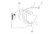
患者は、図2及び図3に示されるように、閉塞型睡眠時無呼吸症候群解消チューブ1を鼻孔21から鼻腔22を通し、閉塞型睡眠時無呼吸症候群解消チューブ1の基端が鼻孔21から僅かに、例えば1〜2cm程度出ている状態までこの閉塞型睡眠時無呼吸症候群解消チューブ1を押し込む。なお、装着前に、閉塞型睡眠時無呼吸症候群解消チューブ1、特にその先端部分にワセリンや、ゼリー状潤滑剤、ゲル物質などの潤滑剤が塗布されるのが好ましい。そして、この結果、閉塞型睡眠時無呼吸症候群解消チューブ1の先端部が患者の咽頭部23の奥まで挿入される。
<How to use obstructive sleep apnea syndrome elimination tube>
(1) Wearing method As shown in FIG. 2 and FIG. 3, the patient passes the obstructive sleep apnea
なお、患者が覚醒時にこの操作を行えば、患者の咽頭部23の気道は開いた状態となっているため、患者は軽い力でこの閉塞型睡眠時無呼吸症候群解消チューブ1の先端部を咽頭部23に押し込むことができる。
Note that if this operation is performed when the patient is awake, the airway of the
(2)脱着方法
患者は、例えば起床時に、閉塞型睡眠時無呼吸症候群解消チューブ1を鼻孔21から引き抜く。
(2) Desorption method The patient pulls out the obstructive sleep apnea
なお、患者は、引き抜かれた閉塞型睡眠時無呼吸症候群解消チューブ1を洗浄、消毒等すれば閉塞型睡眠時無呼吸症候群解消チューブ1を繰り返し使用することができる。なお、閉塞型睡眠時無呼吸症候群解消チューブ1内の洗浄は、適当な清掃器具を使用することにより容易に行うことができ、消毒もアルコール等の消毒薬を使用することによって簡単に行える。
The patient can repeatedly use the obstructive sleep apnea
<第1実施形態に係る閉塞型睡眠時無呼吸症候群解消チューブの特徴>
(1)
第1実施形態に係る閉塞型睡眠時無呼吸症候群解消チューブ1は、鼻孔21から鼻腔22を経て咽頭部23の気道を押し広げるようにして挿入される。このため、この閉塞型睡眠時無呼吸症候群解消チューブ1は、非常に簡易な構成でありながら非常に簡単に装着することができる。したがって、この閉塞型睡眠時無呼吸症候群解消チューブ1は、従来の閉塞型睡眠時無呼吸症候群解消器よりも安価で使いやすい。
<Characteristics of the obstructive sleep apnea syndrome elimination tube according to the first embodiment>
(1)
The obstructive sleep apnea
(2)
第1実施形態に係る閉塞型睡眠時無呼吸症候群解消チューブ1には基端付近に突起部2が形成されている。このため、閉塞型睡眠時無呼吸症候群解消チューブ1が患者の鼻孔に埋没することを防ぐことができる。
(2)
In the obstructive sleep apnea
<第1実施形態の変形例>
(A)
先の実施の形態に係る閉塞型睡眠時無呼吸症候群解消チューブ1では長手方向に直交する面で切った断面形状が円形であったが、長手方向に直交する面で切った断面形状は特に限定されず多角形等であってもよい。
<Modification of First Embodiment>
(A)
In the obstructive sleep apnea
(B)
先の実施の形態に係る閉塞型睡眠時無呼吸症候群解消チューブ1では基端付近にリング状の突起部2が形成されたが、突起部2の形状は特に限定されることはなく、閉塞型睡眠時無呼吸症候群解消チューブ1が患者の鼻孔に埋没しない限り任意の形状とすることができる。
(B)
In the obstructive sleep apnea
(C)
先の実施の形態では特に言及しなかったが、閉塞型睡眠時無呼吸症候群解消チューブ1の外表面を軟質ゴムで覆ってもかまわない。このようにすれば、潤滑剤を利用しなくても、閉塞型睡眠時無呼吸症候群解消チューブ1の装着時において閉塞型睡眠時無呼吸症候群の患者が感じる異物感(違和感)を軽減することができる。
(C)
Although not particularly mentioned in the previous embodiment, the outer surface of the obstructive sleep apnea
(D)
先の実施の形態では特に言及しなかったが、図22に示されるように、閉塞型睡眠時無呼吸症候群解消チューブ1を予め人間の鼻腔内の形状に沿って湾曲させておいてもかまわない。このようにすれば、閉塞型睡眠時無呼吸症候群解消チューブ1の装着時において閉塞型睡眠時無呼吸症候群の患者が感じる異物感(違和感)を軽減することができる。
(D)
Although not particularly mentioned in the previous embodiment, as shown in FIG. 22, the obstructive sleep apnea
(E)
先の実施の形態では特に言及しなかったが、図23に示されるように、閉塞型睡眠時無呼吸症候群解消チューブ1の先端部分の側壁に穴3を開けておいてもかまわない。このようにすれば、閉塞型睡眠時無呼吸症候群解消チューブ1の装着時において閉塞型睡眠時無呼吸症候群の患者が息苦しくなるのを軽減することができる。また、先端部分の側壁のみならず基端部分や中間部分の側壁に穴を開けてもかまわない。
(E)
Although not particularly mentioned in the previous embodiment, as shown in FIG. 23, a
(F)
先の実施の形態では特に言及しなかったが、図24に示されるように、閉塞型睡眠時無呼吸症候群解消チューブ1の先端にガイド部4を設けてもかまわない。なお、このガイド部4は、図24に示されるように、閉塞型睡眠時無呼吸症候群解消チューブ1の先端から突出するように延びている。また、このガイド部4は、薄肉の扁平形状を呈している。
(F)
Although not particularly mentioned in the previous embodiment, as shown in FIG. 24, a
このように閉塞型睡眠時無呼吸症候群解消チューブ1の先端にガイド部4を設ければ、閉塞型睡眠時無呼吸症候群の患者が予め閉塞型睡眠時無呼吸症候群解消チューブ1を鼻孔から入れガイド部4を咽頭部23に挿入した後に眠りについた場合(図25参照)、閉塞型睡眠時無呼吸症候群の患者が睡眠状態に入り気道閉塞状態となったときに咽頭部23を挟む内外空間の気圧差によりガイド部4が自動的に肺側に吸引され、それとともに閉塞型睡眠時無呼吸症候群解消チューブ1が自動的に咽頭部23に挿入されるようになる(図26参照)。このため、この閉塞型睡眠時無呼吸症候群解消チューブ1は、閉塞型睡眠時無呼吸症候群の患者が睡眠状態に入る前までの嚥下(えんげ=つばを呑み込む時に気道が収縮する)時における異物感(違和感)を軽減することができる。
Thus, if the
(G)
先の実施の形態では特に言及しなかったが、図27および図28に示されるように、閉塞型睡眠時無呼吸症候群解消チューブ1の先端に形態変形部5を設け、さらにその先端にガイド部4を設けてもかまわない。なお、形態変形部5は、風船状の部分または切り込み(第4実施形態の変形例(L)の切込部244参照)により形成された部分であって、図27に示されるように、収縮時には基端側に倒れるようにセットされている。また、ガイド部4は、図27および図28に示されるように、形態変形部5の先端から突出するように延びている。また、このガイド部4は、薄肉の扁平形状を呈している。
(G)
Although not particularly mentioned in the previous embodiment, as shown in FIG. 27 and FIG. 28, the
このように閉塞型睡眠時無呼吸症候群解消チューブ1の先端に形態変形部5およびガイド部4を設ければ、閉塞型睡眠時無呼吸症候群の患者が予め閉塞型睡眠時無呼吸症候群解消チューブ1を鼻孔から入れガイド部4を咽頭部23に挿入した後に眠りについた場合(図27参照)、閉塞型睡眠時無呼吸症候群の患者が睡眠状態に入り気道閉塞状態となったときに咽頭部23を挟む内外空間の気圧差によりガイド部4が自動的に肺側に吸引され、それとともに形態変形部5が膨張変形しながら自動的に咽頭部に挿入される(図28参照)。このため、この閉塞型睡眠時無呼吸症候群解消チューブ1は、閉塞型睡眠時無呼吸症候群の患者が睡眠状態に入る前までの嚥下時における異物感(違和感)を軽減することができるとともに咽頭部23に食い込むことができ、睡眠中に患者が寝返りをうっても抜けにくくなる。
Thus, if the shape deformation |
(H)
先の実施の形態に係る閉塞型睡眠時無呼吸症候群解消チューブ1では鼻孔埋没防止のためにリング状の突起部2が採用されたが、第3実施形態の変形例(G)に示される第2風船部135が鼻孔埋没防止のために採用されてもかまわない。なお、かかる場合、基端側の構造は、第3実施形態の変形例(G)に示される閉塞型睡眠時無呼吸症候群解消チューブ31の構造と同様にする必要がある。
(H)
In the obstructive sleep apnea
−第2実施形態−
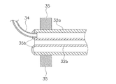
本発明の第2実施形態に係る閉塞型睡眠時無呼吸症候群解消チューブ11は、図4及び図5に示されるように、主に、チューブ12、水膨潤(高吸水性)樹脂塗膜13及び突起部14から構成されている。以下、閉塞型睡眠時無呼吸症候群解消チューブ11の構成要素についてそれぞれ詳述する。
-Second Embodiment-
As shown in FIGS. 4 and 5, the obstructive sleep apnea
<閉塞型睡眠時無呼吸症候群解消チューブの構成>
(1)チューブ
チューブ12は、摩擦係数が低く柔軟性を有し人体に無害である材料、例えば、ポリエチレン、フッ素樹脂、シリコン樹脂等の合成樹脂によって形成されており、鼻孔から上気道の咽頭部までの挿入抵抗が小さい。また、このチューブ12は、閉塞型睡眠時無呼吸症候群解消チューブ装着時に、挿入側先端が咽頭部の僅かに手前に位置し、基端が鼻孔から僅かに突出する位置となる長さとされている。また、このチューブ12の内径は、患者の条件等に応じて適宜設定される。なお、チューブ12の内径は、鼻孔からの挿入を考慮すると、1〜8mm程度が好ましい。また、チューブ12の肉厚は0.5〜3mm程度が好ましい。なお、チューブ12の端面部分は鼻腔への挿入が容易となるように面取り加工が施されるのが好ましい。
<Configuration of obstructive sleep apnea syndrome elimination tube>
(1) Tube The
(2)水膨潤樹脂塗膜
水膨潤樹脂塗膜13は、チューブ12の先端より少し手前の外周面上に形成されている。なお、この水膨潤樹脂塗膜13は閉塞型睡眠時無呼吸症候群解消チューブ装着時に咽頭部に位置するように形成されるのが好ましい。また、水膨潤樹脂としては、例えば、ポリアクリル酸ナトリウム、ポリアクリル酸ナトリウム架橋体、ポリアクリル酸ナトリウム−ビニルアルコール共重合体、ポリビニルアルコール架橋体、セルロース−アクリロニトリルグラフト共重合体、カルボキシメチルセルロース架橋体、でん粉−アクリロニトリルグラフト共重合体、でん粉−アクリル酸グラフト共重合体、でん粉−アクリルアミドグラフト共重合体等が挙げられる。
(2) Water-swelling resin coating film The water-swelling
(3)突起部
突起部14は、閉塞型睡眠時無呼吸症候群解消チューブ11が患者の鼻孔に埋没しないようにするためのものであって、チューブ12の基端近傍に形成されている。なお、この突起部14は、チューブ12の外周面から外側に向かって延びるリング状の突起である。
(3) Protrusion The
<閉塞型睡眠時無呼吸症候群解消チューブの使用方法>
(1)装着方法
患者は、図6及び図7に示されるように、閉塞型睡眠時無呼吸症候群解消チューブ11を鼻孔21から鼻腔22を通し、閉塞型睡眠時無呼吸症候群解消チューブ1の基端が鼻孔21から僅かに、例えば1〜2cm程度出ている状態までこの閉塞型睡眠時無呼吸症候群解消チューブ11を押し込む。なお、装着前に、閉塞型睡眠時無呼吸症候群解消チューブ11の水膨潤樹脂塗膜以外の部分、特に先端部分にワセリンや、ゼリー状潤滑剤、ゲル物質などの潤滑剤が塗布されるのが好ましい。そして、この結果、閉塞型睡眠時無呼吸症候群解消チューブ11の先端部が患者の咽頭部23の奥まで挿入される。
<How to use obstructive sleep apnea syndrome elimination tube>
(1) Wearing method As shown in FIGS. 6 and 7, the patient passes the obstructive sleep apnea
なお、患者が覚醒時にこの操作を行えば、患者の咽頭部23の気道は開いた状態となっているため、患者は軽い力でこの閉塞型睡眠時無呼吸症候群解消チューブ11の先端(水膨潤樹脂塗膜13を含む)を咽頭部23に押し込むことができる。そして、水膨潤樹脂塗膜13は、この状態において咽頭部付近の水分を吸収して膨潤し、咽頭部23に食い込む。
Note that if this operation is performed when the patient is awake, the airway of the
(2)脱着方法
患者は、例えば起床時に、閉塞型睡眠時無呼吸症候群解消チューブ11を鼻孔21から引き抜く。
(2) Desorption method The patient pulls out the obstructive sleep apnea
なお、患者は、引き抜かれた閉塞型睡眠時無呼吸症候群解消チューブ11を洗浄、消毒、乾燥等すれば閉塞型睡眠時無呼吸症候群解消チューブ11を繰り返し使用することができる。なお、閉塞型睡眠時無呼吸症候群解消チューブ11内の洗浄は、適当な清掃器具を使用することにより容易に行うことができ、消毒もアルコール等の消毒薬を使用することによって簡単に行える。
The patient can repeatedly use the obstructive sleep apnea
<第2実施形態に係る閉塞型睡眠時無呼吸症候群解消チューブの特徴>
(1)
第2実施形態に係る閉塞型睡眠時無呼吸症候群解消チューブ11は、鼻孔21から鼻腔22を経て咽頭部23の気道を押し広げるようにして挿入される。このため、この閉塞型睡眠時無呼吸症候群解消チューブ11は、非常に簡易な構成でありながら非常に簡単に装着することができる。したがって、この閉塞型睡眠時無呼吸症候群解消チューブ11は、従来の閉塞型睡眠時無呼吸症候群解消器よりも安価で使いやすい。
<Characteristics of the obstructive sleep apnea syndrome elimination tube according to the second embodiment>
(1)
The obstructive sleep apnea
(2)
第2実施形態に係る閉塞型睡眠時無呼吸症候群解消チューブ11は、装着されると、咽頭部23において水膨潤樹脂塗膜13が咽頭部周辺の水分を吸収して膨潤し咽頭部23に食い込む。このため、閉塞型睡眠時無呼吸症候群解消チューブ11は、患者が寝返りをうっても抜けにくい。
(2)
When the obstructive sleep apnea
(3)
第2実施形態に係る閉塞型睡眠時無呼吸症候群解消チューブ11ではチューブ12の基端付近に突起部14が形成されている。このため、閉塞型睡眠時無呼吸症候群解消チューブ11が患者の鼻孔に埋没することを防ぐことができる。
(3)
In the obstructive sleep apnea
<第2実施形態の変形例>
(A)
先の実施の形態に係る閉塞型睡眠時無呼吸症候群解消チューブ11では長手方向に直交する面で切った断面形状が円形であったが、長手方向に直交する面で切った断面形状は特に限定されず多角形等であってもよい。
<Modification of Second Embodiment>
(A)
In the obstructive sleep apnea
(B)
先の実施の形態に係る閉塞型睡眠時無呼吸症候群解消チューブ11では水膨潤樹脂塗膜13がチューブ12の先端より少し手前の外周面上に形成されていたが、水膨潤樹脂塗膜はチューブ12の外周面全体に形成されてもよい。
(B)
In the obstructive sleep apnea
(C)
先の実施の形態に係る閉塞型睡眠時無呼吸症候群解消チューブ11ではチューブ12の基端付近にリング状の突起部14が形成されたが、突起部14の形状は特に限定されることはなく、閉塞型睡眠時無呼吸症候群解消チューブ11が患者の鼻孔に埋没しない限り任意の形状とすることができる。
(C)
In the obstructive sleep apnea
(D)
先の実施の形態では特に言及しなかったが、閉塞型睡眠時無呼吸症候群解消チューブ11の外表面を軟質ゴムで覆ってもかまわない。このようにすれば、潤滑剤を利用しなくても、閉塞型睡眠時無呼吸症候群解消チューブ11の装着時において閉塞型睡眠時無呼吸症候群の患者が感じる異物感(違和感)を軽減することができる。なお、係る場合、軟質ゴムは水膨潤樹脂塗膜13以外の部分の外表面を覆うように形成されてもかまわないし、また、閉塞型睡眠時無呼吸症候群解消チューブ11の全体又は一部を軟質ゴムで覆った後、その軟質ゴムの上に部分的に水膨潤樹脂塗膜13を形成してもかまわない。
(D)
Although not particularly mentioned in the previous embodiment, the outer surface of the obstructive sleep apnea
(E)
先の実施の形態では特に言及しなかったが、第1実施形態の変形例(D)に示されるように、閉塞型睡眠時無呼吸症候群解消チューブ11を予め人間の鼻腔内の形状に沿って湾曲させておいてもかまわない。このようにすれば、閉塞型睡眠時無呼吸症候群解消チューブ11の装着時において閉塞型睡眠時無呼吸症候群の患者が感じる異物感(違和感)を軽減することができる。
(E)
Although not particularly mentioned in the previous embodiment, as shown in the modified example (D) of the first embodiment, the obstructive sleep apnea
(F)
先の実施の形態では特に言及しなかったが、第1実施形態の変形例(E)に示されるように、閉塞型睡眠時無呼吸症候群解消チューブ11の水膨潤樹脂塗膜13以外の部分の側壁に穴を開けてもかまわない。このようにすれば、閉塞型睡眠時無呼吸症候群解消チューブ11の装着時において閉塞型睡眠時無呼吸症候群の患者が息苦しくなるのを軽減することができる。
(F)
Although not particularly mentioned in the previous embodiment, as shown in the modified example (E) of the first embodiment, the portion other than the water swelling
(G)
先の実施の形態では特に言及しなかったが、第1実施形態の変形例(F)に示されるように、閉塞型睡眠時無呼吸症候群解消チューブ11の先端にガイド部を設けてもかまわない。このようにすれば、この閉塞型睡眠時無呼吸症候群解消チューブ11は、閉塞型睡眠時無呼吸症候群の患者が睡眠状態に入る前までの嚥下(えんげ=つばを呑み込む時に気道が収縮する)時における異物感(違和感)を軽減することができる。
(G)
Although not particularly mentioned in the previous embodiment, as shown in the modified example (F) of the first embodiment, a guide portion may be provided at the tip of the obstructive sleep apnea
(H)
先の実施の形態に係る閉塞型睡眠時無呼吸症候群解消チューブ11では鼻孔埋没防止のためにリング状の突起部14が採用されたが、第3実施形態の変形例(G)に示される第2風船部135が鼻孔埋没防止のために採用されてもかまわない。なお、かかる場合、基端側の構造は、第3実施形態の変形例(G)に示される閉塞型睡眠時無呼吸症候群解消チューブ31の構造と同様にする必要がある。
(H)
In the obstructive sleep apnea
−第3実施形態−
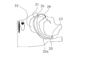
本発明の第3実施形態に係る閉塞型睡眠時無呼吸症候群解消チューブ31は、図8及び図9に示されるように、主に、大径チューブ32a、小径チューブ32b、空気導入チューブ部34及び突起部35から構成されている。以下、閉塞型睡眠時無呼吸症候群解消チューブ31の構成要素についてそれぞれ詳述する。
-Third embodiment-
As shown in FIGS. 8 and 9, the obstructive sleep apnea
<閉塞型睡眠時無呼吸症候群解消チューブの構成>
(1)大径チューブ
大径チューブ32aは、摩擦係数が低く柔軟性を有し人体に無害である材料、例えば、ポリエチレン、フッ素樹脂、シリコン樹脂等の合成樹脂によって形成されており、鼻孔から上気道の咽頭部までの挿入抵抗が小さい。そして、この大径チューブ32aには、図8及び図9に示されるように、先端付近に風船部33が形成されている。なお、この風船部33は、大径チューブ32aと一体に形成されている。この風船部33は、空気圧や水圧等により膨張/収縮が可能となっている。また、この大径チューブ32aは、閉塞型睡眠時無呼吸症候群解消チューブ装着時に、風船部33が咽頭部に位置し、基端が鼻孔から僅かに突出する位置となる長さとされている。また、大径チューブ32aの内径は、患者の条件等に応じて適宜設定されるが、鼻孔からの挿入を考慮すると、5〜8mm程度が好ましい。また、大径チューブ32aの肉厚は0.5〜2mm程度が好ましい。
<Configuration of obstructive sleep apnea syndrome elimination tube>
(1) Large-diameter tube The large-
そして、この大径チューブ32aの先端は、図10に示されるように、第1被覆部35aを介して小径チューブ32bの先端に接合されている。また、この大径チューブ32aの基端は、図11に示されるように、第2被覆部35bを介して小径チューブ32bの基端に接合されている。つまり、小径チューブ32bの開口は開いた状態とされているが、小径チューブ32bと大径チューブ32aとの間の開口は閉じた状態とされている。
And the front-end | tip of this
(2)小径チューブ
小径チューブ32bは、大径チューブ32aに挿通されるチューブであって、その長さは大径チューブ32aの長さに等しくされている。なお、小径チューブ32bの内径は、患者の条件等に応じて適宜設定されるが、大径チューブ32aの内径との関係から1〜5mm程度が好ましい。また、大径チューブ32aの肉厚は0.5〜2mm程度が好ましい。
(2) Small-diameter tube The small-
そして、この小径チューブ32bの先端は、図10に示されるように、第1被覆部35aを介して大径チューブ32aの先端に接合されている。また、小径チューブ32bの基端は、図11に示されるように、第2被覆部35bを介して大径チューブ32aの基端に接合されている。なお、第1被覆部35aは鼻腔への挿入が容易となるように曲面形状とされるのが好ましい。
And the front-end | tip of this
(3)空気導入チューブ部
空気導入チューブ部34は、第2被覆部35bを貫通するように設けられている。そして、この空気導入チューブ部34から空気が吹き込まれると風船部33が膨張し、この空気導入チューブ部34を介して小径チューブ32bの外周面と大径チューブ32aの内周面とに挟まれる空間に存在する空気が抜き取られると風船部33が収縮する。
(3) Air introduction tube part The air
(4)突起部
突起部35は、閉塞型睡眠時無呼吸症候群解消チューブ31が患者の鼻孔に埋没しないようにするためのものであって、大径チューブ32aの基端近傍に形成されている。なお、この突起部35は、大径チューブ32aの外周面から外側に向かって延びるリング状の突起である。
(4) Protrusion The
<閉塞型睡眠時無呼吸症候群解消チューブの使用方法>
(1)装着方法
患者が閉塞型睡眠時無呼吸症候群解消チューブ31を装着するには、患者は、先ず、空気導入チューブ部34を口でくわえて小径チューブ32bと大径チューブ32aとの間の空間に存在する空気を吸引し、図12に示されるように、閉塞型睡眠時無呼吸症候群解消チューブ31の風船部33を収縮させる。次に、患者は、この状態の閉塞型睡眠時無呼吸症候群解消チューブ31を鼻孔21から鼻腔22を通し、閉塞型睡眠時無呼吸症候群解消チューブ31の基端が鼻孔21から僅かに、例えば1〜2cm程度出ている状態までこの閉塞型睡眠時無呼吸症候群解消チューブ31を押し込む。なお、装着前に、閉塞型睡眠時無呼吸症候群解消チューブ31、特にその先端部分にワセリンや、ゼリー状潤滑剤、ゲル物質などの潤滑剤が塗布されるのが好ましい。そして、この結果、風船部33が患者の咽頭部23に挿入される。
<How to use obstructive sleep apnea syndrome elimination tube>
(1) Wearing method In order for the patient to wear the obstructive sleep apnea
そして、患者は、空気導入チューブ部34を口でくわえて小径チューブ32bと大径チューブ32aとの間の空間に空気を吹き込み、図13に示されるように、閉塞型睡眠時無呼吸症候群解消チューブ31の風船部33を膨張させる。この結果、風船部33は、咽頭部23に食い込む。そして、患者は、この状態で空気導入チューブ部34をクリップ等でつまみ空気導入チューブ部34から空気が漏れないようにする。
And a patient blows air in the space between the
なお、患者が覚醒時にこの操作を行えば、患者の咽頭部23の気道は開いた状態となっているため、患者は軽い力でこの閉塞型睡眠時無呼吸症候群解消チューブ31の先端(水膨潤樹脂塗膜13を含む)を咽頭部23に押し込むことができる。
If this operation is performed when the patient is awake, the airway of the
(2)脱着方法
患者は、例えば起床時に、クリップ等をはずした後に空気導入チューブ部34を口でくわえて小径チューブ32bと大径チューブ32aとの間の空間に存在する空気を吸引し、閉塞型睡眠時無呼吸症候群解消チューブ31の風船部33を収縮させる。そして、患者はその状態の閉塞型睡眠時無呼吸症候群解消チューブ31を鼻孔21から引き抜く。
(2) Desorption method When the patient gets up, for example, after removing a clip or the like, the patient sucks air existing in the space between the small-
なお、患者は、引き抜かれた閉塞型睡眠時無呼吸症候群解消チューブ31を洗浄、消毒等を行えば閉塞型睡眠時無呼吸症候群解消チューブ31を繰り返し使用することができる。なお、小径チューブ32b内の洗浄は、適当な清掃器具を使用することにより容易に行うことができ、消毒もアルコール等の消毒薬を使用することによって簡単に行える。
The patient can repeatedly use the obstructive sleep apnea
<閉塞型睡眠時無呼吸症候群解消チューブの特徴>
(1)
第3実施形態に係る閉塞型睡眠時無呼吸症候群解消チューブ31は、鼻孔21から鼻腔2を経て咽頭部23の気道を押し広げるようにして挿入される。このため、この閉塞型睡眠時無呼吸症候群解消チューブ31は、非常に簡易な構成でありながら非常に簡単に装着することができる。したがって、この閉塞型睡眠時無呼吸症候群解消チューブ31は、従来の閉塞型睡眠時無呼吸症候群解消器よりも安価で使いやすい。
<Characteristics of obstructive sleep apnea syndrome elimination tube>
(1)
The obstructive sleep apnea
(2)
第3実施形態に係る閉塞型睡眠時無呼吸症候群解消チューブ31は、患者により空気導入チューブ部34から小径チューブ32bと大径チューブ32aとの間の空間に空気が吹き込まれると風船部33が膨張する。この結果、風船部33は、咽頭部23に食い込む。このため、閉塞型睡眠時無呼吸症候群解消チューブ31は、患者が寝返りをうっても抜けにくい。
(2)
In the obstructive sleep apnea
(3)
第3実施形態に係る閉塞型睡眠時無呼吸症候群解消チューブ31では大径チューブ32aの基端付近に突起部35が形成されている。このため、閉塞型睡眠時無呼吸症候群解消チューブ31が患者の鼻孔に埋没することを防ぐことができる。
(3)
In the obstructive sleep apnea
<第3実施形態の変形例>
(A)
先の実施の形態に係る閉塞型睡眠時無呼吸症候群解消チューブ31では長手方向に直交する面で切った断面形状が円形であったが、長手方向に直交する面で切った断面形状は特に限定されず多角形等であってもよい。
<Modification of Third Embodiment>
(A)
In the obstructive sleep apnea
(B)
先の実施の形態では患者は風船部33が膨張された後に空気導入チューブ部34をクリップ等でつまみ空気導入チューブ部34から空気が漏れないようにしたが、空気導入チューブ部34に予め三方コック等を接続しておいてもよい。
(B)
In the previous embodiment, the patient grips the air
(C)
先の実施の形態に係る閉塞型睡眠時無呼吸症候群解消チューブ31では大径チューブ32aの基端付近にリング状の突起部35が形成されたが、突起部35の形状は特に限定されることはなく、閉塞型睡眠時無呼吸症候群解消チューブ31が患者の鼻孔に埋没しない限り任意の形状とすることができる。
(C)
In the obstructive sleep apnea
(D)
先の実施の形態では特に言及しなかったが、閉塞型睡眠時無呼吸症候群解消チューブ31の外表面(風船部33の外表面を含む)を軟質ゴムで覆ってもかまわない。このようにすれば、閉塞型睡眠時無呼吸症候群解消チューブ31の装着時において閉塞型睡眠時無呼吸症候群の患者が感じる異物感(違和感)を軽減することができる。
(D)
Although not particularly mentioned in the previous embodiment, the outer surface of the obstructive sleep apnea syndrome elimination tube 31 (including the outer surface of the balloon portion 33) may be covered with soft rubber. In this way, when the obstructive sleep apnea
(E)
先の実施の形態では特に言及しなかったが、第1実施形態の変形例(D)に示されるように、閉塞型睡眠時無呼吸症候群解消チューブ31を予め人間の鼻腔内の形状に沿って湾曲させておいてもかまわない。このようにすれば、閉塞型睡眠時無呼吸症候群解消チューブ31の装着時において閉塞型睡眠時無呼吸症候群の患者が感じる異物感(違和感)を軽減することができる。
(E)
Although not particularly mentioned in the previous embodiment, as shown in the modified example (D) of the first embodiment, the obstructive sleep apnea
(F)
先の実施の形態では特に言及しなかったが、第1実施形態の変形例(E)に示されるように、閉塞型睡眠時無呼吸症候群解消チューブ31の先端部分(風船部33を含む)の側壁に穴を開けてもかまわない。このようにすれば、閉塞型睡眠時無呼吸症候群解消チューブ31の装着時において閉塞型睡眠時無呼吸症候群の患者が息苦しくなるのを軽減することができる。また、先端部分の側壁のみならず基端部分や中間部分の側壁に穴を開けてもかまわない。ただし、穴の数や大きさは、風船部33を膨張することができる程度の数や大きさでなければならない。
(F)
Although not particularly mentioned in the previous embodiment, as shown in the modification (E) of the first embodiment, the distal end portion (including the balloon portion 33) of the obstructive sleep apnea
(G)
先の実施の形態に係る閉塞型睡眠時無呼吸症候群解消チューブ31では鼻孔埋没防止のためにリング状の突起部2が採用されたが、図29および図30に示される第2風船部135が鼻孔埋没防止のために採用されてもかまわない。なお、第2風船部135は、風船部33が膨張すると同時に膨張し(図30参照)、風船部33が収縮すると同時に収縮する(図29参照)。このようにすれば、非装着時において閉塞型睡眠時無呼吸症候群解消チューブ31をコンパクトに収納することができる。
(G)
In the obstructive sleep apnea
−第4実施形態−
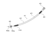
本発明の第4実施形態に係る閉塞型睡眠時無呼吸症候群解消チューブ41は、図14及び図15に示されるように、主に、線材43、チューブ42、固定ストッパー45及び可動ストッパー46から構成されている。以下、閉塞型睡眠時無呼吸症候群解消チューブ41の構成要素についてそれぞれ詳述する。
-Fourth embodiment-
As shown in FIGS. 14 and 15, the obstructive sleep apnea
<閉塞型睡眠時無呼吸症候群解消チューブの構成>
(1)線材
線材43は、チューブ42の内径よりも小さい径を有しており、チューブ42内を往復移動することができる。なお、本実施の形態では、線材43として金属線が利用されている。
<Configuration of obstructive sleep apnea syndrome elimination tube>
(1) Wire rod The
(2)チューブ
チューブ42は、摩擦係数が低く柔軟性を有し人体に無害である材料、例えば、ポリエチレン、フッ素樹脂、シリコン樹脂等の合成樹脂によって形成されており、鼻孔から上気道の咽頭部までの挿入抵抗が小さい。そして、このチューブ42には、図14及び図15に示されるように、先端付近に伸縮部44が形成されている。なお、この伸縮部44は、チューブ42と一体に形成されている。この伸縮部44は、可動ストッパー46により圧縮されると、長手方向に収縮するとともに半径方向外側に突出する。また、このチューブ42は、閉塞型睡眠時無呼吸症候群解消チューブ装着時に、伸縮部44が咽頭部に位置し、基端が鼻孔から僅かに突出する位置となる長さとされている。また、チューブ42の内径は、患者の条件等に応じて適宜設定される。なお、チューブ42の内径は、鼻孔からの挿入を考慮すると、1〜8mm程度が好ましい。また、チューブ42の肉厚は0.5〜3mm程度が好ましい。なお、チューブ42の端面部分は鼻腔への挿入が容易となるように面取り加工が施されるのが好ましい。
(2) Tube The
(3)固定ストッパー
固定ストッパー45は、図14及び図15に示されるように、線材43の先端に固定されている。この固定ストッパー45は、中空球状の金属網体であって通気性を有する。このため、チューブ42の先端が固定ストッパー45に接した状態となっても固定ストッパー45の外部空間は、チューブ42の内部空間と連通する。
(3) Fixed stopper The fixed
(4)可動ストッパー
可動ストッパー46は、ネジ式固定機構を有するスライド式のストッパーであって、円盤体46a及びストッパー本体46bから構成されている。
(4) Movable stopper The
円盤体46aは、チューブ42の外径よりも大きな径を有している。なお、この円盤体46aは閉塞型睡眠時無呼吸症候群解消チューブ41が鼻孔内に入り込むのを防ぐために径が鼻孔よりも大きくなるように形成されている。また、この円盤体46aの中心部は円筒形状を呈しており、その内側には雌ねじがきられている。また、この円盤体46aには、図14に示されるように、中心部を除いた部分に、厚み方向に貫通する6つの貫通孔が形成されている。なお、円盤体46aの中心部は内径がチューブ42の内径よりも小さくなるように形成されており、また、円盤体46aの貫通孔は円盤体46aの中心軸とチューブ42の中心軸とが合わせて接触された状態においてチューブ42の内部空間と連通するように形成されている。
The
ストッパー本体46bは、切頭円錐形状を呈しており、軸に沿って伸びる貫通孔を有する。この貫通孔には、線材43が挿通される。また、ストッパー本体46bには、先端部に長手方向に沿って形成される4本の貫通溝が形成されている。なお、この貫通溝は、ストッパー本体46bの軸に沿って見た場合、貫通孔から放射状に半径方向に伸びている。そして、ストッパ本体46bの先端部(溝が形成されている部分)には雄ねじがきられている。
The stopper
そして、ストッパー本体46bの貫通孔に線材43を通した状態でストッパー本体46bの雄ねじ部が円盤体46aの雌ねじ部に螺合されると、ストッパー本体46bの先端部が除々に挟圧されある地点で線材43を挟持するに至る(固定状態)。一方、雄ねじ部を螺合方向と反対方向に回すと、ストッパー本体46bの先端部が解放され、線材43が自由にスライドできる状態となる(解放状態)。
When the male threaded portion of the stopper
<閉塞型睡眠時無呼吸症候群解消チューブの使用方法>
(1)装着方法
患者が閉塞型睡眠時無呼吸症候群解消チューブ41を装着するには、患者は、先ず、可動ストッパー46を弛めて開放状態とし、図16に示されるように、チューブ42が長手方向に伸びきった状態とする。次に、患者は、この状態の閉塞型睡眠時無呼吸症候群解消チューブ41を鼻孔21から鼻腔22を通し、閉塞型睡眠時無呼吸症候群解消チューブ41の基端が鼻孔21から僅かに、例えば1〜2cm程度出ている状態までこの閉塞型睡眠時無呼吸症候群解消チューブ41を押し込む。なお、このとき、チューブ42の外周面、特にその先端部分の外周面にワセリンや、ゼリー状潤滑剤、ゲル物質などの潤滑剤等が塗布されるのが好ましい。そして、この結果、伸縮部44が患者の咽頭部23に挿入される。
<How to use obstructive sleep apnea syndrome elimination tube>
(1) Wearing method In order for the patient to wear the obstructive sleep apnea
そして、患者は、線材43の基端を一方の手で保持し、他方の手で可動ストッパー46をチューブ側に押し込みチューブ42を圧縮して可動ストッパー46を固定状態とする。すると、図17に示されるように、伸縮部44が半径方向外側に突出し咽頭部23に食い込む。
Then, the patient holds the proximal end of the
なお、患者が覚醒時にこの操作を行えば、患者の咽頭部23の気道は開いた状態となっているため、患者は軽い力でこの閉塞型睡眠時無呼吸症候群解消チューブ41の先端(伸縮部44を含む)を咽頭部23に押し込むことができる。
Note that if this operation is performed when the patient is awake, the airway of the patient's
(2)脱着方法
患者は、例えば起床時に、可動ストッパー46を弛めてチューブ42が伸びきった状態とする。そして、患者はその状態の閉塞型睡眠時無呼吸症候群解消チューブ41を鼻孔21から引き抜く。
(2) Desorption method When the patient wakes up, for example, the
なお、患者は、引き抜かれた閉塞型睡眠時無呼吸症候群解消チューブ41を洗浄、消毒等を行えば閉塞型睡眠時無呼吸症候群解消チューブ41を繰り返し使用することができる。なお、このとき、患者が線材43から可動ストッパー46を取り外せば、その患者はチューブ42から線材43を容易に引き抜くことができる。また、チューブ42内の洗浄は、適当な清掃器具を使用することにより容易に行うことができ、各部の消毒も、アルコール等の消毒薬を使用することによって簡単に行える。
The patient can repeatedly use the obstructive sleep apnea
<閉塞型睡眠時無呼吸症候群解消器の特徴>
(1)
第4実施形態に係る閉塞型睡眠時無呼吸症候群解消チューブ41は、鼻孔21から鼻腔2を経て咽頭部23の気道を押し広げるようにして挿入される。このため、この閉塞型睡眠時無呼吸症候群解消チューブ41は、非常に簡易な構成でありながら非常に簡単に装着することができる。したがって、この閉塞型睡眠時無呼吸症候群解消チューブ41は、従来の閉塞型睡眠時無呼吸症候群解消器よりも安価で使いやすい。
<Characteristics of obstructive sleep apnea syndrome canceller>
(1)
The obstructive sleep apnea
(2)
第4実施形態に係る閉塞型睡眠時無呼吸症候群解消チューブ41は、患者により可動ストッパー46がチューブ側に押し込まれチューブ42が長手方向に沿って圧縮された後に可動ストッパー46が固定状態とされると伸縮部44が半径方向外側に突出する。この結果、伸縮部44は、咽頭部23に食い込む。このため、閉塞型睡眠時無呼吸症候群解消チューブ41は、患者が寝返りをうっても抜けにくい。
(2)
In the obstructive sleep apnea
<変形例>
(A)
先の実施の形態に係る閉塞型睡眠時無呼吸症候群解消チューブ41では固定ストッパー45は中空球状の金属網体であったが、固定ストッパーは図18に示されるような爪型のストッパー45aであってもよい。なお、かかる場合、爪の形状は、閉塞型睡眠時無呼吸症候群解消チューブ41の装着時及び脱着時に患者の咽頭部に引っ掛かることがないような形状とする必要があることに留意すべきである。
<Modification>
(A)
In the obstructive sleep apnea
(B)
先の実施の形態に係る閉塞型睡眠時無呼吸症候群解消チューブ41では線材43に金属線が採用されたが、患者に金属アレルギーの症状がみられる場合には、線材43としてポリエチレンやフッ素樹脂等で被覆された金属線や、純チタンあるいはニッケルを含まないステンレス鋼線、比較的剛直な樹脂繊維等が採用される。また、患者に他の疾病がみられる場合には、症状に応じて適宜な最適な材料が選択される。
(B)
In the obstructive sleep apnea
(C)
先の実施の形態に係る閉塞型睡眠時無呼吸症候群解消チューブ41では固定ストッパー45として中空球状の金属網体が採用されたが、患者に金属アレルギーの症状がみられる場合には、ポリエチレンやフッ素樹脂等で被覆された金属網体や、純チタンあるいはニッケルを含まないステンレス鋼線製の金属網体等が採用される。また、患者に他の疾病がみられる場合には、症状に応じて適宜な最適な材料が選択される。
(C)
In the obstructive sleep apnea
(D)
先の実施の形態に係る閉塞型睡眠時無呼吸症候群解消チューブ41ではチューブ42が、装着時に、伸縮部44が咽頭部23に位置し、基端が鼻孔21から僅かに突出する位置となる長さとされていたが、チューブ42は、装着時に、伸縮部44が咽頭部23に位置し、基端が鼻孔21から僅かに突出する位置となる長さ以上の長さとされてもよい。なお、かかる場合、先の実施形態に係るチューブ42の長さの位置に印を得っておけば患者は使用について困惑することはない。
(D)
In the obstructive sleep apnea
(E)
先の実施の形態では、閉塞型睡眠時無呼吸症候群解消チューブ41は使用後に分解して洗浄されるのが好ましいとされたが、閉塞型睡眠時無呼吸症候群解消チューブ41は使い捨てとされてもよい。なお、かかる場合、可動ストッパー46に取り外し構造を考慮する必要はなく、例えば、ノック式構造等を利用したり線材に段差をつけておいたりすること等ができる。
(E)
In the previous embodiment, the obstructive sleep apnea
(F)
先の実施の形態に係る閉塞型睡眠時無呼吸症候群解消チューブ41では可動ストッパー46としてネジ式固定機構を有するスライド式のストッパーが採用されたが、可動ストッパーはこのようなものに限定されることはなく、嵌め合わせ式固定機構を有するストッパー等が採用されてもよい。
(F)
In the obstructive sleep apnea
(G)
先の実施の形態では可動ストッパー46が採用されていたが、チューブの孔の横断面形状が楕円形や長方形などである場合には可動ストッパー46に代えて線材43から線材43の軸に対して垂直な方向に伸びる線形のストッパー(以下「線形ストッパー」という」)が採用されてもかまわない。
(G)
In the previous embodiment, the
図19には、線形ストッパーが採用される閉塞型睡眠時無呼吸症候群解消チューブ141が例示されている。なお、図中、先の実施の形態に係る閉塞型睡眠時無呼吸症候群解消チューブ41と同じ構成要素については同じ符号で示されている。
FIG. 19 illustrates an obstructive sleep apnea
線形ストッパー146は、図19に示されるように、線材43から線材43の軸に対して垂直な方向に伸びる線材である。なお、このストッパー146は、線材43と一体に形成されている。この線形ストッパー146をより詳細に説明するために、図20に伸縮部44が長手方向に伸びきっている状態にある閉塞型睡眠時無呼吸症候群解消チューブ141を線材43の軸に沿って見た図を示し、図21に伸縮部44が長手方向に縮んでいる状態にある閉塞型睡眠時無呼吸症候群解消チューブ141を線材43の軸に沿って見た図を示した。なお、線形ストッパー146は、図20においてチューブ142の孔内に収容されており、図21においてチューブ142の最後端に接触している。
As shown in FIG. 19, the
なお、この線形ストッパー146が線材43の軸を中心として回転させられると、線材43ごと回転するため、固定ストッパー45も同時に回転することになる。
When the
また、かかる場合、チューブ142の基端近傍に、第1実施形態に示されるようなストッパー2が形成されるのが好ましい。閉塞型睡眠時無呼吸症候群解消チューブ141が患者の鼻孔に埋没することを防ぐためである。
In such a case, it is preferable that the
(H)
先の実施の形態では特に言及しなかったが、閉塞型睡眠時無呼吸症候群解消チューブ41の外表面(伸縮部44の外表面を含む)を軟質ゴムで覆ってもかまわない。このようにすれば、閉塞型睡眠時無呼吸症候群解消チューブ41の装着時において閉塞型睡眠時無呼吸症候群の患者が感じる異物感(違和感)を軽減することができる。
(H)
Although not particularly mentioned in the previous embodiment, the outer surface of the obstructive sleep apnea syndrome elimination tube 41 (including the outer surface of the stretchable part 44) may be covered with soft rubber. In this way, it is possible to reduce the foreign body feeling (uncomfortable feeling) felt by the patient with obstructive sleep apnea syndrome when the obstructive sleep apnea
(I)
先の実施の形態では特に言及しなかったが、第1実施形態の変形例(D)に示されるように、閉塞型睡眠時無呼吸症候群解消チューブ41を予め人間の鼻腔内の形状に沿って湾曲させておいてもかまわない。このようにすれば、閉塞型睡眠時無呼吸症候群解消チューブ41の装着時において閉塞型睡眠時無呼吸症候群の患者が感じる異物感(違和感)を軽減することができる。
(I)
Although not particularly mentioned in the previous embodiment, as shown in the modified example (D) of the first embodiment, the obstructive sleep apnea
(J)
先の実施の形態では特に言及しなかったが、第1実施形態の変形例(E)に示されるように、閉塞型睡眠時無呼吸症候群解消チューブ41の伸縮部44以外の部分の側壁に穴を開けてもかまわない。このようにすれば、閉塞型睡眠時無呼吸症候群解消チューブ41の装着時において閉塞型睡眠時無呼吸症候群の患者が息苦しくなるのを軽減することができる。また、かかる場合、円盤体46aおよびストッパー本体46に貫通孔を形成しなくてもかまわない。
(J)
Although not particularly mentioned in the previous embodiment, as shown in the modified example (E) of the first embodiment, a hole is formed in the side wall of the portion other than the
(K)
先の実施の形態に係る閉塞型睡眠時無呼吸症候群解消チューブ41では鼻孔埋没防止のために可動ストッパー46が採用されたが、図31および図32に示される第2伸縮部144が鼻孔埋没防止のために採用されてもかまわない。なお、第2伸縮部144は、伸縮部44が長手方向に伸びきった状態であるとき、同様に長手方向に伸びきった状態となっており(図31参照)、伸縮部44が半径方向外側に突出すると同時に半径方向外側に突出する(図32参照)。このようにすれば、非装着時において閉塞型睡眠時無呼吸症候群解消チューブ41をコンパクトに収納することができる。また、かかる場合、可動ストッパー46は、鼻孔の大きさよりも小さくてもかまわない。
(K)
In the obstructive sleep apnea
(L)
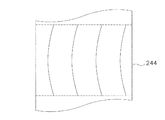
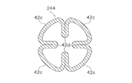
先の実施の形態に係る閉塞型睡眠時無呼吸症候群解消チューブ41では鼻孔埋没防止のために可動ストッパー46が採用されたが、図33および図34に示される切込部244が鼻孔埋没防止のために採用されてもかまわない。なお、切込部244は、伸縮部44が長手方向に伸びきった状態であるとき、同様に長手方向に伸びきった状態となっており(図33参照)、伸縮部44が半径方向外側に突出すると同時に半径方向外側に放射状に(本変形例では4方向に)に突出する(図34参照)。このようにすれば、非装着時において閉塞型睡眠時無呼吸症候群解消チューブ41をコンパクトに収納することができる。
(L)
In the obstructive sleep apnea
なお、切込部244は、チューブ42の軸に平行な4本の切り込み(図35参照)であってもよいし、チューブ42の軸に交差(直交を除く)する切り込み(図36参照)であってもよいし、曲線切り込み(図37及び図38参照)であってもよい。また、切り込み本数は特に限定されず任意に決定してよい。また、この切込部244は、チューブ42に切り込みが入れられることによって形成されてもよいし、図39に示されるように線材や短冊部材の接合によって形成されてもよい。
The
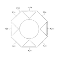
また、図40に示されるように、チューブ42の内側に径の小さなチューブ542を挿通してもかまわない(二重チューブ構造)。かかる場合、内側のチューブ542は、図40に示されるように、切り込み位置が外側のチューブ42の切り込み位置とずれるように外側のチューブ42に挿通される。このような二重チューブ構造が採用される閉塞型睡眠時無呼吸症候群解消器では、可動ストッパー46がチューブ側に押し込まれ両チューブ42,542が圧縮されると、図41に示されるように、外側のチューブ42の切込片42cが半径方向外側に放射状に突出するとともに内側のチューブ542の切込片542cも外側のチューブ42の切込片42cの隙間をぬって半径方向外側に放射状に突出する。なお、内側のチューブ542の切り込み長さ(切込片542cの長さ)は特に限定されないが外側のチューブ42の切り込み長さ(切込片42cの長さ)よりも少し短い方が好ましい。長手方向圧縮時に内側のチューブ542の切込片542cが突出しやすくなるからである。
Further, as shown in FIG. 40, a
なお、切込部244の内側又は外側に、他の切込部を有する短チューブが接合されても上記と同様の作用を得ることができる。また、チューブ42の内側又は外側に、直接、短冊状部材や線材が接合されても上記と同様の作用を得ることができる。なお、かかる場合、切込部の切込片がチューブ42の切込部244の切込片と周方向にずれて重なるように短チューブがチューブ42に接合されることが必須であることは言うまでもない。
In addition, even if the short tube which has another notch part is joined inside or the outer side of the
また、図42〜図44に示されるように、隣接する切込片42cを接合する接合部42dが設けられてもよい。この接合部42dは、図42に示されるように、切込片42cの長手方向中央部分において隣接する切込片42cを接合する。そして、この接合部42dは、チューブ42が長手方向に圧縮される前は図43に示されるように切込片42cの内側に折り畳まれて格納されているが、チューブ42が長手方向に圧縮されると図44に示されるように広がり隣接する切込片42cをほぼ等距離に維持する。
Further, as illustrated in FIGS. 42 to 44, a joining
なお、図42〜図44では接合部42dは切込片42cと一体に形成されているように描画されているが、接合部42dは切込片42cと別部材として形成されてもかまわない。
42 to 44, the
本発明に係る閉塞型睡眠時無呼吸症候群解消チューブは、従来の閉塞型睡眠時無呼吸症候群解消器に比べて安価で使いやすいという特徴を有しており、閉塞型睡眠時無呼吸症候群の解消や治療に一層役立つことが期待される。また、この閉塞型睡眠時無呼吸症候群解消チューブは、救急時や手術時の気道確保具として使用することも可能である。 The obstructive sleep apnea syndrome elimination tube according to the present invention has a feature that it is cheaper and easier to use than conventional obstructive sleep apnea syndrome elimination devices, and eliminates obstructive sleep apnea syndrome. It is expected to be more useful for treatment. Moreover, this obstructive sleep apnea syndrome elimination tube can also be used as an airway securing device during emergency or surgery.
1,11,31,41 閉塞型睡眠時無呼吸症候群解消チューブ
2,14,35 突起部
3 穴(貫通孔)
4 ガイド部
5 形態変形部
12,42 チューブ
13 水膨潤樹脂塗膜
21 鼻孔
22 鼻腔
23 咽頭部
32a 大径チューブ(第1チューブ)
32b 小径チューブ(第2チューブ)
33 風船部(第1風船部)
34 空気導入チューブ部
35a 第1被覆部
35b 第2被覆部
43 線材
44 伸縮部(第1形態変形部)
45,45a 固定ストッパー(第1ストッパー)
46 可動ストッパー(第2ストッパー)
46a 円盤体
46b ストッパー本体
135 第2風船部
144 第2伸縮部(第2形態変形部)
146 線形ストッパー
244 切込部(第2形態変形部)
1,11,31,41 Obstructive sleep apnea
4 Guide
32b Small diameter tube (second tube)
33 Balloon part (first balloon part)
34 Air introduction tube part 35a 1st coating |
45, 45a Fixed stopper (first stopper)
46 Movable stopper (second stopper)
146
Claims (16)
請求項1に記載の閉塞型睡眠時無呼吸症候群解消チューブ。 The obstructive sleep apnea syndrome elimination tube according to claim 1, wherein a gel substance is applied to all or a part of the outer peripheral surface.
請求項1に記載の閉塞型睡眠時無呼吸症候群解消チューブ。 The obstructive sleep apnea syndrome elimination tube according to claim 1, wherein soft rubber is applied to all or a part of the outer peripheral surface.
請求項1から3のいずれかに記載の閉塞型睡眠時無呼吸症候群解消チューブ。 The obstructive sleep apnea syndrome elimination tube according to any one of claims 1 to 3, further comprising a protrusion extending outward from the outer peripheral surface.
請求項1から4のいずれかに記載の閉塞型睡眠時無呼吸症候群解消チューブ。 The obstructive sleep apnea syndrome elimination tube according to any one of claims 1 to 4, wherein all or part of the tube is curved.
請求項1から5のいずれかに記載の閉塞型睡眠時無呼吸症候群解消チューブ。 The obstructive sleep apnea syndrome elimination tube according to any one of claims 1 to 5, further comprising a through-hole penetrating the side wall.
請求項1から6のいずれかに記載の閉塞型睡眠時無呼吸症候群解消チューブ。 The obstructive sleep apnea syndrome elimination tube according to any one of claims 1 to 6, further comprising a flat guide portion extending so as to protrude from the tip.
前記形態変形部の先端から突出するように延びる扁平形状のガイド部と
を備える請求項1から6のいずれかに記載の閉塞型睡眠時無呼吸症候群解消チューブ。 A shape deformable portion provided at the tip and deformable in the longitudinal direction and the radial direction;
The obstructive sleep apnea syndrome elimination tube according to any one of claims 1 to 6, further comprising a flat guide portion extending so as to protrude from a tip of the deformable portion.
請求項1から7のいずれかに記載の閉塞型睡眠時無呼吸症候群解消チューブ。 The obstructive sleep apnea syndrome elimination tube according to any one of claims 1 to 7, wherein a water swelling resin is applied to the whole or a part of the outer peripheral surface.
前記第1チューブに所定の隙間をもって挿入される第2チューブと
を備える閉塞型睡眠時無呼吸症候群解消チューブ。 A first tube having a first balloon portion that can be inflated and deflated;
An obstructive sleep apnea syndrome elimination tube comprising a second tube inserted into the first tube with a predetermined gap.
請求項10に記載の閉塞型睡眠時無呼吸症候群解消チューブ。 The obstructive sleep apnea syndrome elimination tube according to claim 10, wherein one end of the first tube and one end of the second tube are joined.
請求項10又は11に記載の閉塞型睡眠時無呼吸症候群解消チューブ。 The obstructive sleep apnea syndrome elimination tube according to claim 10 or 11, further comprising a protrusion extending outward from an outer peripheral surface of the first tube.
前記第1チューブは、基端側に、膨張及び収縮可能な第2風船部をさらに有する
請求項10から12のいずれかに記載の閉塞型睡眠時無呼吸症候群解消チューブ。 The first balloon part is provided on the tip side of the first tube,
The obstructive sleep apnea syndrome eliminating tube according to any one of claims 10 to 12, wherein the first tube further includes a second balloon portion that can expand and contract on a proximal end side.
前記チューブに所定の隙間をもって挿通される線材と、
通気部を有し、前記線材の第1端側に取り付けられる第1ストッパーと、
前記線材の第1端の反対側の端である第2端側に取り付けられる第2ストッパーと
を備える閉塞型睡眠時無呼吸症候群解消チューブ。 A tube having a first shape deformable portion deformable in the longitudinal direction and the radial direction;
A wire inserted through the tube with a predetermined gap;
A first stopper having a ventilation portion and attached to the first end of the wire;
An obstructive sleep apnea syndrome elimination tube comprising: a second stopper attached to a second end which is an end opposite to the first end of the wire.
請求項14に記載の閉塞型睡眠時無呼吸症候群解消チューブ。 The obstructive sleep apnea syndrome elimination tube according to claim 14, wherein the second stopper has a ventilation portion and is slidable along the wire.
前記チューブは、基端側に、長手方向及び径方向に変形可能な第2形態変形部をさらに有する
請求項14または15に記載の閉塞型睡眠時無呼吸症候群解消チューブ。 The first form deforming portion is provided on the distal end side of the tube,
The obstructive sleep apnea syndrome eliminating tube according to claim 14 or 15, wherein the tube further has a second shape deformable portion deformable in a longitudinal direction and a radial direction on a proximal end side.
Priority Applications (1)
| Application Number | Priority Date | Filing Date | Title |
|---|---|---|---|
| JP2008220069A JP2009072581A (en) | 2007-08-30 | 2008-08-28 | Obstructive sleep apnea syndrome dissolving tube |
Applications Claiming Priority (2)
| Application Number | Priority Date | Filing Date | Title |
|---|---|---|---|
| JP2007223949 | 2007-08-30 | ||
| JP2008220069A JP2009072581A (en) | 2007-08-30 | 2008-08-28 | Obstructive sleep apnea syndrome dissolving tube |
Publications (2)
| Publication Number | Publication Date |
|---|---|
| JP2009072581A true JP2009072581A (en) | 2009-04-09 |
| JP2009072581A5 JP2009072581A5 (en) | 2011-10-13 |
Family
ID=40608171
Family Applications (1)
| Application Number | Title | Priority Date | Filing Date |
|---|---|---|---|
| JP2008220069A Pending JP2009072581A (en) | 2007-08-30 | 2008-08-28 | Obstructive sleep apnea syndrome dissolving tube |
Country Status (1)
| Country | Link |
|---|---|
| JP (1) | JP2009072581A (en) |
Cited By (10)
| Publication number | Priority date | Publication date | Assignee | Title |
|---|---|---|---|---|
| WO2010113305A1 (en) * | 2009-04-01 | 2010-10-07 | 株式会社アイ.エス.テイ | Tube for resolving obstructive sleep apnea syndrome |
| WO2011108282A1 (en) | 2010-03-05 | 2011-09-09 | 株式会社アイ.エス.テイ | Clip for a nasal cavity insertion device, and nasal cavity insertion device set provided with said clip |
| WO2011108253A1 (en) | 2010-03-05 | 2011-09-09 | 株式会社アイ.エス.テイ | Nasal cavity insertion device |
| CN103533978A (en) * | 2011-05-13 | 2014-01-22 | 七梦科技有限公司 | Clip for nasal intubation device and nasal intubation device set provided with said clip |
| WO2014163110A2 (en) * | 2013-04-02 | 2014-10-09 | セブン ドリーマーズ ラボラトリーズ,インコーポレイテッド | Nasal intubation tube |
| USD723680S1 (en) | 2011-09-05 | 2015-03-03 | Seven Dreamers Laboratories, Inc. | Nasal airway tube |
| WO2016003163A1 (en) * | 2014-07-01 | 2016-01-07 | Catholic Kwandong University Industry Cooperation Foundation | Support for nose surgery |
| USD777316S1 (en) | 2014-03-07 | 2017-01-24 | Seven Dreamers Laboratories, Inc. | Nasal airway tube |
| JP2017093905A (en) * | 2015-11-26 | 2017-06-01 | 信越ポリマー株式会社 | Tube instrument for being inserted into nasal cavity |
| WO2018121459A1 (en) * | 2016-12-26 | 2018-07-05 | 吴丽秋 | Collapsible nasal-cavity spray catheter |
Citations (8)
| Publication number | Priority date | Publication date | Assignee | Title |
|---|---|---|---|---|
| JPS5041370A (en) * | 1973-03-08 | 1975-04-15 | ||
| JPS62500566A (en) * | 1984-10-22 | 1987-03-12 | デイコムド コ−ポレイシヨン | Endotracheal tube for vocalization |
| JPH03504935A (en) * | 1989-03-29 | 1991-10-31 | ヤロスラフスキ メゾトラスレボイ ナウチノ―テフニチェスキ ツェントル | Device for sinusitis treatment |
| JP2002531187A (en) * | 1998-12-02 | 2002-09-24 | トラコエ メディカル ゲーエムベーハー | Tube with sealed cuff |
| JP2003265621A (en) * | 2002-03-14 | 2003-09-24 | Univ Nihon | Indwelling and collecting type stent for disease in sleep apnea syndrome |
| JP2006204630A (en) * | 2005-01-28 | 2006-08-10 | Makoto Sato | Obstructive sleep apnea syndrome dissolving device |
| JP2006528524A (en) * | 2003-05-15 | 2006-12-21 | ミクロクッフ ジーエムビーエッチ | Respiratory aid |
| JP2008149089A (en) * | 2006-12-19 | 2008-07-03 | New Wave Medical:Kk | Catheter for nasal cavity dilation |
-
2008
- 2008-08-28 JP JP2008220069A patent/JP2009072581A/en active Pending
Patent Citations (8)
| Publication number | Priority date | Publication date | Assignee | Title |
|---|---|---|---|---|
| JPS5041370A (en) * | 1973-03-08 | 1975-04-15 | ||
| JPS62500566A (en) * | 1984-10-22 | 1987-03-12 | デイコムド コ−ポレイシヨン | Endotracheal tube for vocalization |
| JPH03504935A (en) * | 1989-03-29 | 1991-10-31 | ヤロスラフスキ メゾトラスレボイ ナウチノ―テフニチェスキ ツェントル | Device for sinusitis treatment |
| JP2002531187A (en) * | 1998-12-02 | 2002-09-24 | トラコエ メディカル ゲーエムベーハー | Tube with sealed cuff |
| JP2003265621A (en) * | 2002-03-14 | 2003-09-24 | Univ Nihon | Indwelling and collecting type stent for disease in sleep apnea syndrome |
| JP2006528524A (en) * | 2003-05-15 | 2006-12-21 | ミクロクッフ ジーエムビーエッチ | Respiratory aid |
| JP2006204630A (en) * | 2005-01-28 | 2006-08-10 | Makoto Sato | Obstructive sleep apnea syndrome dissolving device |
| JP2008149089A (en) * | 2006-12-19 | 2008-07-03 | New Wave Medical:Kk | Catheter for nasal cavity dilation |
Cited By (23)
| Publication number | Priority date | Publication date | Assignee | Title |
|---|---|---|---|---|
| WO2010113305A1 (en) * | 2009-04-01 | 2010-10-07 | 株式会社アイ.エス.テイ | Tube for resolving obstructive sleep apnea syndrome |
| US9724228B2 (en) | 2010-03-05 | 2017-08-08 | Seven Dreamers Laboratories, Inc. | Nasal cavity insertion device fixture and nasal cavity insertion device set including the same |
| WO2011108253A1 (en) | 2010-03-05 | 2011-09-09 | 株式会社アイ.エス.テイ | Nasal cavity insertion device |
| JP2011200626A (en) * | 2010-03-05 | 2011-10-13 | Ist Corp | Nasal cavity insertion device |
| JP5839360B2 (en) * | 2010-03-05 | 2016-01-06 | seven dreamers laboratories株式会社 | Nasal cavity insertion device fixture and nasal cavity insertion device set including the nasal cavity insertion device fixture |
| WO2011108282A1 (en) | 2010-03-05 | 2011-09-09 | 株式会社アイ.エス.テイ | Clip for a nasal cavity insertion device, and nasal cavity insertion device set provided with said clip |
| US9492309B2 (en) | 2010-03-05 | 2016-11-15 | Seven Dreamers Laboratories, Inc. | Nasal cavity insertion device |
| EP3120888A1 (en) | 2010-03-05 | 2017-01-25 | seven dreamers laboratories, Inc. | Nasal cavity insertion device fixture and nasal cavity insertion device set including the same |
| CN103533978A (en) * | 2011-05-13 | 2014-01-22 | 七梦科技有限公司 | Clip for nasal intubation device and nasal intubation device set provided with said clip |
| USD723680S1 (en) | 2011-09-05 | 2015-03-03 | Seven Dreamers Laboratories, Inc. | Nasal airway tube |
| WO2014163110A2 (en) * | 2013-04-02 | 2014-10-09 | セブン ドリーマーズ ラボラトリーズ,インコーポレイテッド | Nasal intubation tube |
| WO2014163110A3 (en) * | 2013-04-02 | 2014-11-27 | セブン ドリーマーズ ラボラトリーズ,インコーポレイテッド | Nasal intubation tube |
| JPWO2014163110A1 (en) * | 2013-04-02 | 2017-02-16 | seven dreamers laboratories株式会社 | Nasal tube |
| USD777316S1 (en) | 2014-03-07 | 2017-01-24 | Seven Dreamers Laboratories, Inc. | Nasal airway tube |
| KR101592019B1 (en) * | 2014-07-01 | 2016-02-04 | 가톨릭관동대학교 산학협력단 | Supporter for nasal surgery |
| WO2016003163A1 (en) * | 2014-07-01 | 2016-01-07 | Catholic Kwandong University Industry Cooperation Foundation | Support for nose surgery |
| JP2017093905A (en) * | 2015-11-26 | 2017-06-01 | 信越ポリマー株式会社 | Tube instrument for being inserted into nasal cavity |
| WO2018121459A1 (en) * | 2016-12-26 | 2018-07-05 | 吴丽秋 | Collapsible nasal-cavity spray catheter |
| CN110799166A (en) * | 2016-12-26 | 2020-02-14 | 吴丽秋 | Collapsible nasal cavity jet catheter |
| AU2017385152B2 (en) * | 2016-12-26 | 2020-07-09 | Hui-Shuan Lee | Collapsible nasal ejecting catheter |
| EP3560476A4 (en) * | 2016-12-26 | 2020-07-29 | Lih-Chiu Wu | Collapsible nasal-cavity spray catheter |
| US11000450B2 (en) | 2016-12-26 | 2021-05-11 | Lih-Chiu Wu | Collapsible nasal ejecting catheter |
| CN110799166B (en) * | 2016-12-26 | 2021-12-14 | 吴丽秋 | Collapsible nasal cavity jet catheter |
Similar Documents
| Publication | Publication Date | Title |
|---|---|---|
| JP2009072581A (en) | Obstructive sleep apnea syndrome dissolving tube | |
| JP2009072581A5 (en) | ||
| US10085873B2 (en) | Nasal congestion and obstruction relief and breathing assist devices | |
| US8056562B2 (en) | System and method for providing support for a breathing passage | |
| US10492932B2 (en) | Device for splinting a cavity, organ duct and/or vessel | |
| US20100331777A1 (en) | Nose device | |
| US20200215285A1 (en) | Tracheal tube and suction device | |
| JP4982047B2 (en) | Obstructive sleep apnea syndrome resolver | |
| US20040020492A1 (en) | Upper airway device and method | |
| JP2009072582A (en) | Obstructive sleep apnea syndrome dissolving device | |
| US20020177871A1 (en) | Nasal breathing assist devices | |
| JP2008100034A (en) | Fixing device for endotracheal tube | |
| CA2371435A1 (en) | Laryngeal mask adapter | |
| JP2008178654A (en) | Protector for nasal cavity | |
| JP6473459B2 (en) | Tracheal tube system | |
| US20100217302A1 (en) | Mechanically deployable upper airway stent | |
| US20170049981A1 (en) | Nasopharyngeal device for obstructive sleep apnea syndrome | |
| KR102010191B1 (en) | Extension for snoring prevention | |
| KR20000068452A (en) | Device for preventing snoring and apnoea during sleep | |
| WO2010113305A1 (en) | Tube for resolving obstructive sleep apnea syndrome | |
| US20080257357A1 (en) | Dental laryngeal mask | |
| US7021314B1 (en) | Stoma stent with integrated speech flap valve | |
| JP2009034384A (en) | Obstructive sleep apnea syndrome dissolving device | |
| CN106659861A (en) | Device | |
| KR20170027754A (en) | Endotracheal tube |
Legal Events
| Date | Code | Title | Description |
|---|---|---|---|
| RD02 | Notification of acceptance of power of attorney |
Free format text: JAPANESE INTERMEDIATE CODE: A7422 Effective date: 20090413 |
|
| RD04 | Notification of resignation of power of attorney |
Free format text: JAPANESE INTERMEDIATE CODE: A7424 Effective date: 20090424 |
|
| A521 | Written amendment |
Free format text: JAPANESE INTERMEDIATE CODE: A523 Effective date: 20110821 |
|
| A621 | Written request for application examination |
Free format text: JAPANESE INTERMEDIATE CODE: A621 Effective date: 20110824 |
|
| A711 | Notification of change in applicant |
Free format text: JAPANESE INTERMEDIATE CODE: A711 Effective date: 20120130 |
|
| A521 | Written amendment |
Free format text: JAPANESE INTERMEDIATE CODE: A821 Effective date: 20120131 |
|
| A521 | Written amendment |
Free format text: JAPANESE INTERMEDIATE CODE: A523 Effective date: 20120302 |
|
| RD02 | Notification of acceptance of power of attorney |
Free format text: JAPANESE INTERMEDIATE CODE: A7422 Effective date: 20120703 |
|
| A521 | Written amendment |
Free format text: JAPANESE INTERMEDIATE CODE: A523 Effective date: 20120706 |
|
| A131 | Notification of reasons for refusal |
Free format text: JAPANESE INTERMEDIATE CODE: A131 Effective date: 20121227 |
|
| A977 | Report on retrieval |
Free format text: JAPANESE INTERMEDIATE CODE: A971007 Effective date: 20121228 |
|
| A521 | Written amendment |
Free format text: JAPANESE INTERMEDIATE CODE: A523 Effective date: 20130308 |
|
| A131 | Notification of reasons for refusal |
Free format text: JAPANESE INTERMEDIATE CODE: A131 Effective date: 20130927 |
|
| A02 | Decision of refusal |
Free format text: JAPANESE INTERMEDIATE CODE: A02 Effective date: 20140304 |